EP1921845A2 - Lens controlling apparatus and image-taking apparatus - Google Patents
Lens controlling apparatus and image-taking apparatus Download PDFInfo
- Publication number
- EP1921845A2 EP1921845A2 EP08151321A EP08151321A EP1921845A2 EP 1921845 A2 EP1921845 A2 EP 1921845A2 EP 08151321 A EP08151321 A EP 08151321A EP 08151321 A EP08151321 A EP 08151321A EP 1921845 A2 EP1921845 A2 EP 1921845A2
- Authority
- EP
- European Patent Office
- Prior art keywords
- signal
- focus
- image
- microcomputer
- evaluation value
- Prior art date
- Legal status (The legal status is an assumption and is not a legal conclusion. Google has not performed a legal analysis and makes no representation as to the accuracy of the status listed.)
- Granted
Links
Images


Classifications
-
- H—ELECTRICITY
- H04—ELECTRIC COMMUNICATION TECHNIQUE
- H04N—PICTORIAL COMMUNICATION, e.g. TELEVISION
- H04N23/00—Cameras or camera modules comprising electronic image sensors; Control thereof
- H04N23/60—Control of cameras or camera modules
- H04N23/67—Focus control based on electronic image sensor signals
- H04N23/672—Focus control based on electronic image sensor signals based on the phase difference signals
-
- H—ELECTRICITY
- H04—ELECTRIC COMMUNICATION TECHNIQUE
- H04N—PICTORIAL COMMUNICATION, e.g. TELEVISION
- H04N23/00—Cameras or camera modules comprising electronic image sensors; Control thereof
- H04N23/60—Control of cameras or camera modules
- H04N23/67—Focus control based on electronic image sensor signals
- H04N23/673—Focus control based on electronic image sensor signals based on contrast or high frequency components of image signals, e.g. hill climbing method
-
- H—ELECTRICITY
- H04—ELECTRIC COMMUNICATION TECHNIQUE
- H04N—PICTORIAL COMMUNICATION, e.g. TELEVISION
- H04N23/00—Cameras or camera modules comprising electronic image sensors; Control thereof
- H04N23/60—Control of cameras or camera modules
- H04N23/63—Control of cameras or camera modules by using electronic viewfinders
-
- H—ELECTRICITY
- H04—ELECTRIC COMMUNICATION TECHNIQUE
- H04N—PICTORIAL COMMUNICATION, e.g. TELEVISION
- H04N23/00—Cameras or camera modules comprising electronic image sensors; Control thereof
- H04N23/60—Control of cameras or camera modules
- H04N23/695—Control of camera direction for changing a field of view, e.g. pan, tilt or based on tracking of objects
Abstract
Description
- The present invention relates to lens controlling apparatuses used for image-taking apparatus such as video cameras.
- In video cameras, a so-called TV-AF method is recently a standard method for focus control, in which an AF evaluation value signal is generated based on sharpness (a contrast state) of images detected from video signals obtained by photoelectrical conversion of an object image with an image-pickup element, and then focus control is performed so that a position of a focus lens, where the AF evaluation value signal may become maximum, is searched.
- Generally, a high frequency component extracted from the video signals is used as the AF evaluation value signal in the TV-AF method. The AF evaluation value signal becomes larger as the position of the focus lens approaches an in-focus point (in-focus position) when taking an image of a normal object, as shown in
Fig. 2 . The position where the level (value) of the AF evaluation value signal reaches the maximum is the in-focus point. - Moreover, there is an internal phase difference detecting method as another AF method, in which a luminous flux that have passed through a pupil of an image-taking optical system is divided into two luminous fluxes, and a pair of focus detecting sensors (line sensors) receive the two luminous fluxes, respectively. An out-of-focus amount and an out-of-focus direction can be directly calculated based on a displacement amount between signals output according to the light-receiving amounts of the sensors, that is, relative positional displacement amount of the luminous fluxes in the dividing direction thereof.
- By the use of this method, the out-of-focus amount and the out-of-focus direction can be obtained if an accumulation operation in the focus detecting sensor is performed once. Therefore, a high-speed focus adjustment operation becomes possible.
- Moreover, there is an external distance-measuring method using a distance-measuring sensor that is independent of the image-taking lens. In this method, a luminous flux from an object is divided into two luminous fluxes, and two focus detecting sensors receive the two luminous fluxes respectively. A displacement amount between signals output according to the light-receiving amounts of the sensors, that is, a relative positional displacement amount of the luminous fluxes in the dividing direction thereof, is detected, and an object distance is calculated by triangulation.
- There are other methods using an external distance-measuring sensor such as a method in which an object distance is measured based on a transmission speed of ultrasonic waves detected by an ultrasonic sensor, and a method in which an object distance is measured by triangulation using an infrared sensor.
- Furthermore, an AF method as a combination of the TV-AF method and an AF method other than the TV-AF method has been proposed, in which, for instance, a focus lens is moved to the vicinity of an in-focus point by the internal phase difference detecting method, and then moved to the in-focus point more accurately by the TV-AF method (see
Japanese Laid-Open Patent Application No.H05-64056 - However, the TV-AF method includes the following disadvantages. First, since the AF evaluation value signal is generated from video signals, the AF evaluation value signal may fluctuate according to the changes of objects and image-taking conditions. In this case, the focus lens may be driven in a false direction (in a direction away from the in-focus point) because of the misjudgment of an in-focus direction.
- Moreover, in a case where, from a state in which the image-taking optical system has focused on a certain distance object, the object moved out of an image-taking area, if the AF evaluation value for an out-of-focus object that does not exist at the certain distance is equal to the AF evaluation value for the certain distance object, the AF operation may not be restarted, and therefore out-of-focus images may be taken continuously.
- In the combination of the TV-AF method and an AF method other than the TV-AF method, the focus lens is moved to the vicinity of the in-focus point by an AF method other than the TV-AF method, and the AF method is then changed to the TV-AF method only when the AF evaluation value is larger than a predetermined level (when the focus lens is within an in-focus range) to move the focus lens to the in-focus point.
- However, in a case where the AF evaluation value has changed by the change of the object's contrast despite in a state in which the object distance has not changed, the focus state may change because of the operation of the TV-AF in the image-taking condition requiring no movements of the focus position originally, and unnecessary image blur may be generated.
- Such an unnecessary TV-AF operation is allowable in an image-taking apparatus in which image recording is not performed during the AF operation. However, in an image-taking apparatus in which video image recording is also performed during the AF operation, image blur caused by the unnecessary TV-AF operation will be recorded.
- Furthermore, if the AF method with the external distance-measuring sensor, which is an AF method other than the TV-AF method, is adopted, parallax between the image-taking area of the image-taking lens and the distance-measuring area of the distance-measuring sensor mayt be generated. In this case, the focus lens may move according to the change of the object distance detected by the external distance-measuring sensor though it is in an in-focus state, and image blur may occur.
- An object of the present invention is to provide a lens controlling apparatus capable of preventing an execution of irrelevant AF control caused by the changes of objects and image-taking conditions in a combination of the TV-AF method and an AF method other than the TV-AF method, and to provide an image-taking apparatus with the same.
- One aspect of the present invention is a lens controlling apparatus, which performs a focus control operation for an image-taking optical system, comprising:
- a first signal generating section, which generates a first signal showing a contrast state of an object image on the basis of a predetermined frequency component of a signal obtained by using an image-pickup element that photoelectrically converts the object image; a second signal generating section, which generates a second signal by a focus detecting method different from that in the first signal generating section; and a controller, which selectively performs a first focus control operation based on the first signal and a second focus control operation based on the second signal. The controller selects one of the first and second focus control operations in accordance with each change amount of the first and second signals.
- Another aspect of the present invention is a lens controlling apparatus, which performs focus control for a focus lens included in an image-taking optical system, comprising: a first signal generating section, which generates a first signal showing a contrast state of an object image on the basis of a predetermined frequency component of a signal obtained by using an image-pickup element that photoelectrically converts the object image; a second signal generating section, which generates a second signal by a focus detecting method different from that in the first signal generating section; and a controller, which selectively performs a first focus control operation based on the first signal and a second focus control operation based on the second signal. The controller selects whether to drive the focus lens by at least one of the first and second focus control operations or to stop the drive of the focus lens in accordance with each change amount of the first and second signals.
- Another aspect of the present invention is a focus controlling method for an image-taking optical system, comprising: a first step of generating a first signal showing a contrast state of an object image on the basis of a predetermined frequency component of a signal obtained by using an image-pickup element that photoelectrically converts the object image; a second step of generating a second signal by a focus detecting method different from that in the first step; and a third step of selectively performing a first focus control operation based on the first signal and a second focus control operation based on the second signal. The third step selects one of the first and second focus control operations in accordance with each change amount of the first and second signals.
- Still another aspect of the present invention is a focus controlling method for a focus lens included in an image-taking optical system, comprising: a first step of generating a first signal showing a contrast state of an object image on the basis of a predetermined frequency component of a signal obtained by using an image-pickup element that photoelectrically converts the object image; a second step of generating a second signal by a focus detecting method different from that in the first step; and a third step of selectively performing a first focus control operation based on the first signal and a second focus control operation based on the second signal. The third step selects whether to drive the focus lens by at least one of the first and second focus control operations or to stop the drive of the focus lens in accordance with each change amount of the first and second signals.
- Other objects and further features of the present invention will become readily apparent from the following description of the preferred embodiments with reference to accompanying drawings.
-
Fig.1 is a block diagram showing the structure of a video camera that isEmbodiment 1 of the present invention. -
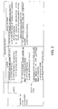
Fig.2 is a classification table of image-taking scenes. -
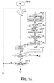
Figs.3A and3B are flowcharts showing AF control in the video camera ofEmbodiment 1. -
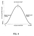
Fig.4 is a graph showing a relation between AF evaluation values and positions of a focus lens unit. -
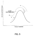
Fig.5 is a figure for explaining the outline of a mountaineering drive of the focus lens unit of AF control. -
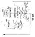
Figs.6A and6B are flowcharts showing AF control in the video camera ofEmbodiment 1. -
Fig.7 is a flowchart showing AF control in the video camera ofEmbodiment 1. -
Fig.8 is a figure for explaining the outline of a minute drive of the focus lens unit of AF control. -
Fig.9 is a block diagram showing the structure of a video camera that isEmbodiment 2 of the present invention. -
Figs. 10A and10B are flowcharts showing AF control in the video camera of Embodiment 2. - A description will now be given of the preferred embodiments of the present invention by referring to the accompanying drawings.
-
Fig.1 shows the structure of a video camera as an image-taking apparatus that is Embodiment1 of the present invention. InFig.1 , in order from an object side (the left side in the figure), thereference numeral 101 denotes a fixed first lens unit, 102 denotes a magnification-varying lens unit for varying the magnification, 103 denotes a stop, 104 denotes a fixed second lens unit, and 105 denotes a focus/compensator lens unit (hereinafter, it is referred to as a focus lens unit) for correcting an image plane fluctuation with a variation of magnification and focusing. An image-taking optical system (hereinafter, it is referred to as an image-taking lens) is constituted by these lens units and the stop.
The actual each lens unit can be constituted by a plurality of lenses though each lens unit in the figure seems to be constituted by a single lens. - In the embodiment, a video camera with an image-taking lens will be explained. However, the present invention can be applied to a video camera on which an image-taking lens can detachably mount.
- The
reference numeral 106 denotes an image-pickup element such as a CCD sensor and a CMOS sensor, and 107 denotes a CDS/AGC circuit that samples outputs from the image-pickup element 106 and performs gain adjustment. Thereference numeral 108 denotes a camera signal processing circuit that processes video signals that are output signals from the CDS/AGC circuit 107 so that they become signals corresponding to an after-mentionedrecording unit 109. - The
recording unit 109 records the signals processed by the camerasignal processing circuit 108 to recording medium such as magnetic tapes, semiconductor memories and optical discs. - The
reference numeral 110 denotes a zoom motor that drives the magnification-varying lens unit focus lens unit 105. - The
reference numeral 112 denotes an AF gate that passes only a signal component used for focus detection among the video signals from the CDS/AGC circuit 107. Thereference numeral 113 denotes an AF signal processing circuit that is a first signal generating section, which extracts a predetermined high-frequency component from the signals that have output from the CDS/AGC circuit 107 and generates an AF evaluation value signal that is a first signal based on the high-frequency component. The AF evaluation value signal shows a contrast state of an object image formed by the image-taking lens. - The
reference numeral 112 denotes a camera/AF microcomputer (hereinafter, it is merely referred to as a microcomputer), which is a controller, that controls thefocus motor 111 for driving thefocus lens unit 105 based on the AF evaluation value signal output from the AFsignal processing circuit 113 and a distance signal, which is a second signal, that output from an external distance-measuring unit 126, described later. Themicrocomputer 114 controls the image-pickup element 106, CDS/AGC circuit 107, camerasignal processing circuit 108, AFsignal processing circuit 113, therecording unit 109 and the like. - The
reference numeral 115 denotes a display unit that displays video images corresponding to the output signals from the camerasignal processing circuit 108. A user can see the taken video images through thedisplay unit 115. Thereference numeral 116 denotes a zoom switch. Themicrocomputer 114 controls themotors zoom switch 116, and thereby driving the magnification-varyinglens unit 102 and thefocus lens unit 105 for zooming. - The external distance-measuring
unit 126, which is a second signal generating section, measures a distance to the object, and outputs a distance-measuring signal according to the measured distance. The external distance-measuringunit 126 can employ any external distance-measuring method such as an external phase difference detecting method, ultrasonic sensor method and infrared sensor method and the like. - Next, the AF control that is performed by the
microcomputer 114 will be explained. Themicrocomputer 114 in this embodiment determines a current image-taking situation based on the AF evaluation value signal (hereinafter, it is referred to as an AF evaluation value, too) obtained by the TV-AF method (AF signal processing circuit 113) and the distance signal (hereinafter, it is referred to as distance information, too) obtained by the external distance-measuring method (external distance-measuring unit 126), and selects an AF operation method that is optimal for the current image-taking situation. This AF control can achieve focusing that matches the user's intention and an AF function without false operations. - Specifically, the
microcomputer 114 determines the image-taking situation according to the change amount of the object distance, the change amount of the AF evaluation value and the level (value) of the AF evaluation value as shown in the table ofFig.2 , and optimizing the AF method and transition of AF processing states. - More specifically, the
microcomputer 114 controls the selection of the AF method and the transition of AF processing states (transition of AF modes) so as to compensate weaknesses of the TV-AF method such as: - 1) the
microcomputer 114 cannot judge whether the object distance has changed or the object's contrast has changed; - 2) the
microcomputer 114 cannot judge whether the object has a low contrast or it is an out-of-focus state, and so as to reduce affects of parallax in the external distance measuring method such as: - 3) the
microcomputer 114 detects the distance to an object other than the main object because of the difference between the sensing angle of the external distance measuring sensor and viewing angle of the image-taking lens. - A classification table of five image-taking scenes is described in the table of
Fig.2 . Hereinafter, a determination method of image-taking scenes, and the transition of AF modes and the selection of the AF processing method (TV-AF method or external distance measuring method) in each scene will be explained using the table. - This
scene 1 is an assumed scene in which the object distance changes with panning, tilting or the like. In this scene, it is necessary to perform the AF control at once for obtaining an in-focus state. - The judgment condition of this scene is that the fluctuation of the AF evaluation value is large and the fluctuation of the distance information is also large.
- In this scene, the
microcomputer 114 sets a restart mode for the AF mode, and sets a combination method for the AF method, in which rapid focusing is performed by the use of the external distance measuring method and then performed more accurate focusing by the use of the TV-AF method. - This
scene 2 is an assumed scene in which the contrast of an equidistant object changes. In this scene, themicrocomputer 114 maintains the current position of thefocus lens unit 105 or drives it within a range in which the in-focus state may be kept for the slight change of the object distance based on the current position of thefocus lens unit 105 without unconsidered drive or large drive of thefocus lens unit 105. - The judgment condition of this scene is that the fluctuation of the AF evaluation value is large and the fluctuation of the distance information is zero or very small.
- In this scene, the
microcomputer 114 sets an in-focus confirmation mode for the AF mode, and sets a combination method for the AF method ,in which focusing is performed so as to follow the slight change of the distance information by the use of the external distance measuring method while the AF evaluation value is changing, and performed so as to reconfirm the in-focus state by the use of the TV-AF method after the AF evaluation value has become stable. Since the distance information is generally stable during focus-following, the position of the focus lens unit 105 (hereinafter, it is referred to as a focus position) is maintained. - This
scene 1 is an assumed scene in which the parallax is generated between the sensing angle of the external distance-measuringsensor 126 and the viewing angle of the image-taking lens. In this scene, themicrocomputer 114 performs the AF control operation based on the AF evaluation value of the TV-AF without using the distance information from the external distance-measuringsensor 126. - The judgment condition of this scene is that the fluctuation of the AF evaluation value is zero or very small and the level of the AF evaluation value is high, and the fluctuation of the distance information is large.
- In this scene, the
microcomputer 114 sets the restart mode for the AF mode, and sets the TV-AF method for the AF method. - This
scene 4 is an assumed scene in which the object has a low contrast, and the object distance changes with panning or the like. In this scene, it is necessary to perform the AF control at once for obtaining an in-focus state. However, so-called hunting may occur because the level of the AF evaluation value is low, and an AF evaluation value for the determination of the in-focus state cannot be obtained. - The judgment condition of this scene is that the fluctuation of the AF evaluation value is zero or very small and the level of the AF evaluation value is low, and the fluctuation of the distance information is large.
- In this scene, the
microcomputer 114 sets the restart mode for the AF mode, and sets a combination method for an AF method to in which focusing is performed so as to follow the change of the distance information by the use of the external distance measuring method while the AF evaluation value is low, and performed so as to confirm the in-focus state by the use of the TV-AF method after the AF evaluation value has become high. - This
scene 1 is an assumed scene in which the object distance and the contrast of the object do not change, and the video camera is supported with a tripod or the like. In this scene, it is necessary to maintain the in-focus position. - The judgment condition of this scene is that the fluctuation of the AF evaluation value is zero or very small, and the fluctuation of the distance information is zero or very small.
- In this scene, the
microcomputer 114 sets a mode for the AF mode, in which the current focus position is maintained, and sets an AF lock state, in which themicrocomputer 114 do not select the AF method until the next change of the scene. - The process according to a focus control program in the
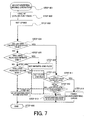
microcomputer 114 will be explained, which determines one of the above-mentioned five representative scenes and performs the AF control, using a flowchart inFigs. 3A and3B (hereinafter, they are referred to asFig.3 ). - First, the
microcomputer 114 starts the process in accordance with the application of power inStep 301, and selects a primary signal for the AF control inStep 322. In other words, themicrocomputer 114 selects the AF method (whether to perform the AF control by the TV-AF method, which is the first focus control operation, or to perform the AF control by the external distance-measuring method, which is the second focus control operation). The selection is performed based on the results of Steps319 , 320 and 329, described later, the external distance-measuring method being selected as the default setting at the time of the application of power. - The process progresses to the
Step 302 if the TV-AF method has been selected, and to theStep 323 if the external distance-measuring method has been selected. - In
Step 302, themicrocomputer 114 performs a 'minute drive operation' of the TV-AF method, judges whether it is the in-focus state or not, and judges which direction the in-focus point is in if it is not the in-focus state. After that, themicrocomputer 114 progresses to Step 305. The 'minute drive operation' will be explained below. - In
Step 305, themicrocomputer 114 judges whether an in-focus judgment has been done inStep 302. The process progresses to Step 311 if the in-focus judgment has been done, and themicrocomputer 114 performs an 'in-focus/restart judging process'. The process progresses to Step 306 if the in-focus judgment has not been done. - In
Step 306, themicrocomputer 114 judges whether the direction judgment has been done inStep 302, and the process progresses to Step 307 if the direction judgment has been done. On the other hand, the process returns to Step 302 viaStep 322 if the direction judgment has not been done; themicrocomputer 114 continues the 'minute drive operation'. - In
Step 307, themicrocomputer 114 performs a 'mountaineering drive operation' for thefocus lens unit 105 at a predetermined speed. The 'mountaineering drive operation' will be explained below. - In
Step 308, themicrocomputer 114 judges whether the AF evaluation value exceeds the peak in the 'mountaineering drive operation' inStep 307 or not. The relation between the AF evaluation value and the position of thefocus lens unit 105 is shown inFig.4 . - In
Fig.4 , the focus position where the AF evaluation value becomes the peak is the in-focus point, and image blur becomes larger and the AF evaluation value becomes lower as the focus position moves to the infinite side and the close side from there. After thefocus lens unit 105 was driven in a direction in which the AF evaluation value became larger in the 'mountaineering drive operation' as shown by the solid arrow inFig.5 , an AF evaluation value smaller than the previous AF evaluation value shows that the previous AF evaluation value was the peak (that is, the AF evaluation value has exceeded the peak). Therefore, thefocus lens unit 105 can be located at the in-focus point by returning it to the previous position. - The process progresses to Step 309 if the
microcomputer 114 judged that the AF evaluation value has exceeded the peak. On the other hand, the process returns to Step 307 if themicrocomputer 114 judged that the AF evaluation value has not exceeded the peak; themicrocomputer 114 continues the 'mountaineering drive operation'. - In
Step 309, themicrocomputer 114 returns thefocus lens unit 105 to the position where the AF evaluation value becomes the peak. - In
Step 309, themicrocomputer 114 judges whether thefocus lens unit 105 has returned to the position where the AF evaluation value becomes the peak (in-focus point) or not. The process returns to Step 302 viaStep 322 if thefocus lens unit 105 has returned to the in-focus point; themicrocomputer 114 performs the 'minute drive operation' again. The process returns to Step 309 if thefocus lens unit 105 has not returned to the in-focus point; themicrocomputer 114 continues the operation for returning thefocus lens unit 105 to the in-focus point. - Next, the 'in-focus/restart judging process' from
Step 311 will be explained. - First, in
Step 311, themicrocomputer 114 drives thefocus lens unit 105 to the judged in-focus point.
InStep 312, themicrocomputer 114 judges whether thefocus lens unit 105 has reached the in-focus point or not, and the process progresses to Step 313 if thefocus lens unit 105 has reached the in-focus point. On the other hand, the process progresses to Step 311 if thefocus lens unit 105 has not reached the in-focus point. - In
Step 313, themicrocomputer 114 holds the AF evaluation value and the distance information from the external distance-measuringunit 126 at the in-focus point. Next, inStep 314, themicrocomputer 114 takes the latest AF evaluation value and distance information. - In
Step 315, themicrocomputer 114 compares the previous distance information that was held inStep 313 with the latest (current) distance information that was taken inStep 314, and judges whether the difference between them, that is, the change amount of the distance information, which is the second signal, is larger than a predetermined amount (second predetermined amount) or not. This judgment can be a judgment of whether the change amount is larger or smaller than a predetermined value as one value, and can be a judgment of whether the change amount is larger than the upper limit or smaller than the lower limit of a range having a certain width. If the change amount of the distance information is larger than the above-mentioned predetermined amount, the process progresses to Step 315. - Next, in
Step 317, themicrocomputer 114 compares the latest (current) AF evaluation value that was taken inStep 314 with the previous AF evaluation value that was held inStep 313, and judges whether the difference between them, that is, the change amount of the AF evaluation value, which is the first signal, is larger than a predetermined amount (first predetermined amount) or not. This judgment may also be a judgment of whether the change amount is larger or smaller than a predetermined value as one value, and may be a judgment of whether the change amount is larger than the upper limit or smaller than the lower limit of a range having a certain width. - If the change amount of the AF evaluation value is larger than the above-mentioned predetermined amount, the process progresses to Step 319. In
Step 319, themicrocomputer 114 sets the external distance-measuring method for the AF method in the next AF control operation, and the process returns to Step 322. In this case, the process progresses fromStep 322 to Step 323; the AF mode changes to the 'restart mode'. The process in this case corresponds to a process for the above-mentionedscene 1. On the other hand, if the change amount of the AF evaluation value is smaller than the predetermined amount, that is, zero or very small inStep 317, the process progresses to Step 318. InStep 318, themicrocomputer 114 judges whether the level of the current (latest) AF evaluation value taken inStep 314 is smaller than a predetermined threshold or not. The case that the AF evaluation value is smaller than the threshold corresponds to thescene 4, in which the distance to the low contrast object was changed. In this case, the process progresses to Step 319; the AF mode changes to the 'restart mode'. - The case that the AF evaluation value is larger than the threshold corresponds to the
scene 3, in which there is a parallax between the image-taking lens and the external distance-measuringunit 126. In this case, the process progresses to Step 320; themicrocomputer 114 sets the TV-AF method for the AF method in the next AF control operation. Moreover, the process progresses fromStep 322 to Step 302; the AF mode changes to the 'restart mode'. - On the other hand, if the change amount of the distance information is smaller than the predetermined amount, that is, zero or very small in
Step 315, the process progresses to Step 316. InStep 316, themicrocomputer 114 compares the current AF evaluation value that was taken inStep 314 with the previous AF evaluation value that was held inStep 313, as inStep 317, and judges whether the change amount of the AF evaluation value is larger than the predetermined amount (first predetermined amount) or not. If the change amount of the AF evaluation value is larger than the predetermined amount, the process progresses to Step 319; themicrocomputer 114 sets the external distance-measuring method for the AF method in the next AF control operation. - Then, the process returns to Step 322; the 'restart mode' is performed from
Step 323. At this time, since the distance information changes little, themicrocomputer 114 controls thefocus lens unit 105 so that the current position of thefocus lens unit 105 may be almost held. This situation corresponds to thescene 2, in which panning or the like is performed for an equidistant object. In this situation, the object distance does not change, but the contrast of the object changes. Therefore, the situation is determined to be a situation in which the AF evaluation value has fluctuated because of the change of the object' contrast. - If the change amount of the AF evaluation value is smaller than the predetermined amount in
Step 316, the process progresses to Step 321; the AF mode changes to a mode in which the position of thefocus lens unit 105 is held, that is, the movement of thefocus lens unit 105 is prohibited (in other words, the drive of thefocus lens unit 105 is stopped). Then, the process returns to Step 314; the 'in-focus/restart judging process' is continued. This case corresponds to thescene 5, in which the contrast and distance of the object do not change. - The case that the process progresses to Step 323 via
Steps scenes microcomputer 114 selects the external distance-measuring method inStep 322, the process progresses to Step 323. InStep 323, themicrocomputer 114 calculates an in-focus point (hereinafter, it is referred to as a distance-measured in-focus point) of thefocus lens unit 105 based on the latest distance information taken inStep 324 while taking the AF evaluation value, and drives thefocus lens unit 105 to the distance-measured in-focus point. - Next, in
Step 325, themicrocomputer 114 judges whether thefocus lens unit 105 has reached the distance-measured in-focus point or not. If thefocus lens unit 105 has not reached the distance-measured in-focus point, the process returns to Step 323; themicrocomputer 114 waits for reaching. - Since the
scene 1 is a situation in which the object distance change has surely occurred, themicrocomputer 114 drives thefocus lens unit 105 to the distance-measured in-focus point at a high speed as an AF restart operation, resulting in achieving the in-focus state rapidly. In addition, since thescene 2 is a situation in which the object distance change has been zero (or very small), the distance-measured in-focus point is approximately the same. Therefore, themicrocomputer 114 almost holds thefocus lens unit 105 at the position at the time of the judgment inStep 316. Furthermore, since thescene 4 is a situation in which the object distance has changed, themicrocomputer 114 drives thefocus lens unit 105, resulting in achieving the in-focus state rapidly, as in thescene 1. - If the
focus lens unit 105 has reached the distance-measured in-focus point inStep 325, themicrocomputer 114 takes the AF evaluation value again inStep 326, and judges whether the change amount that is the difference amount from the AF evaluation value taken and held inStep 323 is larger than the predetermined amount (first predetermined amount) or not inStep 327, as inStep 317. - If the change amount of the AF evaluation value is larger than the predetermined amount, the situation corresponds to the
scene 2. Therefore, themicrocomputer 114 performs the process fromStep 323 for holding the position of thefocus lens unit 105, continuing the focus control operation by the external distance-measuring method. If the fluctuation of the AF evaluation value becomes small because of a stable camerawork, the process progresses to Step 329 viaStep 328; themicrocomputer 114 sets the TV-AF method for the AF method in the next AF operation, and the AF mode changes to the 'in-focus confirming mode'. - In
Step 328, themicrocomputer 114 judges whether the level of the current AF evaluation value is smaller than the predetermined threshold or not as inStep 318. If the level of the current AF evaluation value is smaller than the threshold, themicrocomputer 114 judges that it is thescene 4, and returns to Step 323, continuing the focus control operation by the external distance-measuring method. - When the object changes to an object with a contrast larger than a certain degree, since the level of the AF evaluation value becomes larger than the predetermined threshold in
Step 328, the process progresses to Step 329. InStep 329, themicrocomputer 114 sets the TV-AF method for the AF method in the next AF control operation as described above, and changes the AF mode to the in-focus confirming mode'. - As explained above, in the embodiment, the AF method is selected so that weaknesses of the TV-AF method and the external distance-measuring method may be compensated for each other, based on the change amount of the AF evaluation value and the change amount of the distance information, that is, according to the change of image-taking situations. Therefore, it is possible to reduce the possibility of false focus control. In particular, it becomes possible to prevent false operations caused by the parallax between the image-taking lens and external distance-measuring
unit 126. - In addition, it becomes possible to achieve operations for natural focusing in all image-taking scenes by selecting a mode in which the position of the
focus lens unit 105 is held and a mode in which the position of thefocus lens unit 105 is changed (that is, the focus control is performed) in accordance with image-taking scenes. - These operations make it possible to move the
focus lens unit 105 to the in-focus position rapidly, and to prevent the movement of thefocus lens unit 105 in a false direction and the suspension of the movement of thefocus lens unit 105 in a state in which there is image blur. Therefore, it becomes possible to perform auto focus operations at high speeds and with high accuracy. - Hereinafter, further explanations for the process in the 'minute drive operation' and 'mountaineering drive operation' according to the focus control program in the
microcomputer 114 will be given. - First, the 'minute drive operation' will be explained using a flowchart in
Figs.6A and6B (hereinafter, they are merely referred to asFig.6 ). - The
microcomputer 114 starts the process inStep 401, and judges whether the current mode number (Mode) is 0 or not inStep 402. The process progresses to Step 403 if the Mode is 0, and to Step 412 if the Mode is not 0. - In
Step 403, themicrocomputer 114 takes the AF evaluation value from the AFsignal processing circuit 113. This AF evaluation value was generated based on the video signals made from charges accumulated in the image-pickup element 106 when thefocus lens unit 105 is located on the infinite side in the Mode of 2. - Next, in
Step 404, themicrocomputer 114 stores the AF evaluation value taken inStep 403 as an infinite-side AF evaluation value. - Next, in
Step 405, themicrocomputer 114 judges whether the directions that have judged to be the in-focus direction are continuously the same the first predetermined times (shown by 'predetermined times 1' in the figure) or not. The process progresses to Step 408 if it is yes, and to Step 406 if it is no. - In
Step 406, themicrocomputer 114 determines the average position of thefocus lens unit 105 for the past-predetermined period to be an in-focus point. - In
Step 407, themicrocomputer 114 judges whether thefocus lens unit 105 has moved back and forth in the same area the second predetermined times (shown by 'predetermined times 2' in the figure) or not. The process progresses to Step 409 if it is yes, that is, thefocus lens unit 105 is located in the vicinity of the in-focus point, and the process progresses to Step 410 if it is no. - In
Step 410, themicrocomputer 114 increases the Mode (returns to 0 after the Mode has reached 3, changing it cyclically), and then the process progresses to Step 305 inFig.3 . - In the process from
Step 410 to Step 411, if the process shown inFig.6 is finished, themicrocomputer 114 will determine that it is 'NO' inSteps Fig. 3 , and then will continue the 'minute drive operation' in Step 302 (the process fromStep 401 inFig.6 ) again. - On the other hand, in Step 408, the
microcomputer 114 determines that the direction judgment has been done, and then the process progresses to Step 411 for finishing the process. In this case, themicrocomputer 114 will determine that it is 'NO' inStep 305 inFig.3 . In contrast, themicrocomputer 114 will determine that it is 'YES' inStep 306, and then will perform the 'mountaineering drive operation'. - In
Step 409, themicrocomputer 114 determines that the in-focus judgment has been done, and then the process progresses to Step 411 for finishing the process. In this case, themicrocomputer 114 will determine that it is 'YES' inStep 305 inFig.3 , and then will perform the 'in-focus/restart judging process' fromStep 311 inFig. 3 . - In
Step 412, themicrocomputer 114 judges whether the current Mode is 1 or not. The process progresses to Step 413 if it is yes; themicrocomputer 114 performs the process for driving thefocus lens unit 105 in the infinite direction. The process progresses to Step 418 if it is no inStep 412. - In
Step 413, themicrocomputer 114 calculates a vibration amplitude and a center movement amplitude in the 'minute drive operation'. The amplitude is generally set to be small when the depth of focus is shallow, and to be large when the depth of focus is deep. - In
Step 414, themicrocomputer 114 compares the infinite-side AF evaluation value in the Mode=0, which was mentioned above, with a close-side AF evaluation value in the Mode=3, which will be mentioned later. The process progresses to Step 415 if the infinite-side AF evaluation value is larger than the close-side AF evaluation value, and to Step 416 if the infinite-side AF evaluation value is smaller than the close-side AF evaluation value. - In
Step 415, themicrocomputer 114 sets the sum of the vibration amplitude and center movement amplitude for a drive amplitude. - In
Step 416, themicrocomputer 114 sets the vibration amplitude for the drive amplitude. - In
Step 417, themicrocomputer 114 drives thefocus lens unit 105 in the infinite direction with the amplitude set inStep 415 orStep 416, and then performs the process fromStep 415 described above. - In
Step 418, themicrocomputer 114 judges whether the current Mode is 2 or not. The process progresses to Step 419 if it is yes. InStep 419, themicrocomputer 114 performs a process corresponding to the case where thefocus lens unit 105 is judged to be in the infinite side in the minute drive. On the other hand, in the case where thefocus lens unit 105 is judged to be in the close side in the minute drive, the process progresses to Step 421. - In
Step 419, themicrocomputer 114 takes the AF evaluation value from the AFsignal processing circuit 113. This AF evaluation value was generated based on the video signals made from charges accumulated in the image-pickup element 106 when thefocus lens unit 105 is located on the close side and the Mode is 0. - Next, in
Step 420, themicrocomputer 114 stores the AF evaluation value taken inStep 419 as a close-side AF evaluation value. Then, the process progresses to Step 405 described above. - In
Step 421, themicrocomputer 114 calculates a vibration amplitude and a center movement amplitude in the 'minute drive operation'. The amplitude is generally set to be small when the depth of focus is shallow, and to be large when the depth of focus is deep. - In
Step 422, themicrocomputer 114 compares the infinite-side AF evaluation value in the Mode=0, which was mentioned above, with a close-side AF evaluation value in the Mode=3, which was mentioned above. The process progresses to Step 423 if the close-side AF evaluation value is larger than the infinite-side AF evaluation value, and to Step 424 if the close-side AF evaluation value is smaller than the infinite-side AF evaluation value. - In
Step 423, themicrocomputer 114 sets the sum of the vibration amplitude and center movement amplitude for the drive amplitude. - In
Step 424, themicrocomputer 114 sets the vibration amplitude for the drive amplitude. - Next, in
Step 425, themicrocomputer 114 drives thefocus lens unit 105 in the close direction with the amplitude set inStep 423 orStep 424, and then performs the process fromStep 405 described above. -
Fig.8 shows the movement of thefocus lens unit 105 with time. The horizontal axis shows time, and the vertical axis shows the focus position. In addition, the downward-convex portions of the pulse wave shown in the upper part inFig.8 show synchronization signals of video signals. - In
Fig.8 , the AF evaluation value EVA for charges (shown by a hatched ellipse) accumulated in the image-pickup element 106 during a period A is taken at the time TA, and the AF evaluation value EVB for charges accumulated in the image-pickup element 106 during a period B is taken at the time TB. The AF evaluation values EVA and EVB are compared with each other at the time TC. If the AF evaluation value EVB is larger than the AF evaluation value EVA, the vibration center is moved (the drive amplitude = the vibration amplitude + the center movement amplitude). On the other side, if the AF evaluation value EVA is larger than the AF evaluation value EVB, the vibration center is not moved (the drive amplitude = the vibration amplitude). - Next, the explanation for the process in the 'mountaineering drive operation' according to the focus control program in the
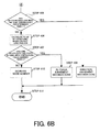
microcomputer 114 will be given. - The
microcomputer 114 starts the process inStep 601, and takes the AF evaluation value takes from the AFsignal processing circuit 113 inStep 602. - Next, in
Step 603, themicrocomputer 114 sets the mountaineering drive speed. The speed is generally set to be small when the depth of field is shallow, and to be large when the depth of field is deep. - Next, in
Step 604, themicrocomputer 114 judges whether the AF evaluation value taken inStep 602 is smaller than the previous AF evaluation value by a predetermined amount or not. The process progresses to Step 605 if it is no, and to Step 611 if it is yes. The predetermined amount is determined in consideration of the S/N ratio of the AF evaluation value, and is set to an amount more than the change width of the AF evaluation value in a state in which the object and the position of thefocus lens unit 105 are fixed, respectively, otherwise it is impossible to perform the mountaineering drive in the correct direction because of affects of the fluctuation of the AF evaluation value. InStep 605, themicrocomputer 114 judges whether thefocus lens unit 105 has reached the infinite end. The infinite end in the embodiment is the most infinite side position in the movable range of thefocus lens unit 105, which is set in design. The process progresses to Step 609 if thefocus lens unit 105 has reached the infinite end, and to Step 606 if thefocus lens unit 105 has not reached. InStep 606, themicrocomputer 114 judges whether thefocus lens unit 105 has reached the close end. The close end in the embodiment is the most close side position in the movable range of thefocus lens unit 105, which is set in design. The process progresses to Step610 if thefocus lens unit 105 has reached the close end, and to Step 607 if thefocus lens unit 105 has not reached there. - In
Step 609, themicrocomputer 114 set a flag showing the infinite end. InStep 610, themicrocomputer 114 set a flag showing the close end. The process progresses to Step613 fromSteps - In
Step 613, themicrocomputer 114 continues the mountaineering drive of thefocus lens unit 105 in the direction opposite to the end shown by the above-mentioned flag. - In
Step 607, themicrocomputer 114 continues the mountaineering drive of thefocus lens unit 105 in the same direction as in the last time at a predetermined speed. Then, the process progresses to theStep 608, finishing the mountaineering drive operation' process. - In
Step 611, themicrocomputer 114 judges whether the AF evaluation value has decreased over the peak (seeFig. 5 ) or not. The process progresses to theStep 612 if the AF evaluation value has not decreased over the peak. On the other hand, the process progresses to theStep 614 if the AF evaluation value has decreased over the peak, finishing the mountaineering drive. Then, the process progresses to theStep 608, finishing the 'mountaineering drive operation' process and starting the 'minute drive operation' process. - In
Step 612, themicrocomputer 114 judges whether the AF evaluation value has decreased continuously the third predetermined times (shown by 'predetermined times 3' in the figure) or not. The process progresses to Step 613 if it is yes, and to Step 607 if it is no. InStep 607, themicrocomputer 114 performs the mountaineering drive of thefocus lens unit 105 in the same direction as in the last time at the predetermined speed. Then, the process progresses to theStep 608, finishing the mountaineering drive operation' process. - In
Step 613, themicrocomputer 114 performs the mountaineering drive of thefocus lens unit 105 in the direction opposite to that in the last time at the predetermined speed. Then, the process progresses to theStep 608, finishing the 'mountaineering drive operation' process. -
Fig.5 shows the movement of thefocus lens unit 105 at the time of the mountaineering drive mentioned above. The vertical axis shows the AF evaluation value, and the horizontal axis shows the focus position. The arrow C shows that the AF evaluation value decreases over the peak. In this case, the mountaineering drive is finished because thefocus lens unit 105 has passed over the in-focus point. On the other hand, the arrow D shows that the AF evaluation value decreases without exceeding the peak. In this case, the mountaineering drive is continued after the direction is switched because of a mistake in direction. -
Fig.9 shows the structure of a video camera as an image-taking apparatus that isEmbodiment 2 of the present invention. In this embodiment, the same reference numerals are used for the constituents common toEmbodiment 1, and explanations thereof are omitted. - In above-mentioned
Embodiment 1, a video camera performing the second focus control operation with the external distance-measuring method was explained. In contrast, in this embodiment, a video camera performing a second focus control operation with a TTL (Through the Taking-Lens) phase difference detecting method, that is, an internal phase difference detecting method will be explained. - In
Fig.9 , an image-taking lens is constituted by, in order from an object side (the left side in the figure), afirst lens unit 101, a magnification-varyinglens unit 102, a focus lens unit (focus/compensator lens unit) 105, astop 103, and an image-forminglens unit 120. The image-forminglens unit 120 is arranged between thestop 103 and an image-pickup element 106. - The
reference numeral 121 denotes a half prism dividing light for auto focus, which is arranged between thefocus lens unit 105 and thestop 103. The reference numeral 122 denotes a sub mirror reflecting the luminous flux from thehalf prism reference numeral 125 denotes an AF circuit, which is a second signal generating section, with line sensors (AF sensors) 124 for the phase difference detecting method. - The
microcomputer 114 detects an out-of-focus amount (defocus amount) and out-of-focus direction (defocus direction) of the image-taking lens based on the output from theAF sensors 124 via theAF circuit 125. - In the video camera with such a structure, the
stop 103 operates actually during moving image-taking. Therefore, it is necessary to divide the luminous flux that entered the image-taking lens with thehalf prism 121 on the front side of thestop 103. - An AF control algorithm similar to that of
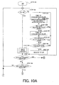
Embodiment 1 can be applied to this embodiment.Figs.10A and10B (hereinafter, it is merely referred to asFig.10 ) show a flowchart indicating the feature of the embodiment. - This flowchart is used in place of the flowchart in
Fig.3 forEmbodiment 1; the same symbols as inFig.3 are applied to the common steps in this flowchart.
InFig.3 , the distance information is used inSteps Fig.10 , the internal out-of-focus information (defocus amount and defocus direction) is used inSteps Figs.3 and10 . - In the embodiment, the AF method is selected so that weaknesses of the TV-AF method and the internal phase difference detecting method may be compensated for each other, based on the change amount of the AF evaluation value and the change amount of the internal out-of-focus information, that is, according to the change of image-taking situations. Therefore, it is possible to reduce the possibility of false focus control.
- In addition, it becomes possible to achieve operations for natural focusing in all image-taking scenes by selecting a mode in which the position of the
focus lens unit 105 is held and a mode in which the position of thefocus lens unit 105 is changed (that is, the focus control is performed) in accordance with image-taking scenes. - These operations make it possible to move the
focus lens unit 105 to the in-focus position rapidly, and to prevent the movement of thefocus lens unit 105 in a false direction and the suspension of the movement of thefocus lens unit 105 in a state in which there is image blur. Therefore, it becomes possible to perform auto focus operations at high speeds and with high accuracy. - According to each embodiment described above, the optimal AF method can be selected based on the changes of the first and second signals corresponding to the changes of the object and image-taking situations. Therefore, it is possible to reduce the possibility of inadequate focus control such as driving a focus lens in a false direction, causing unnecessary image blur and stopping a focus lens in an image-blurred state.
- A lens controlling apparatus is disclosed, which is capable of preventing an execution of irrelevant AF control in a combination of TV-AF method and an AF method other than the TV-AF method. The lens controlling apparatus comprises: a first signal generating section generating a first signal showing a contrast state of an object image on the basis of a predetermined frequency component of a signal; a second signal generating section generating a second signal by a focus detecting method different from that in the first signal generating section; and a controller, which selects one of a first focus control operation based on the first signal and a second focus control operation based on the second signal in accordance with each change amount of the first and second signals.
- In addition, the present application comprises the following subject matter:
- 1. A lens controlling apparatus, which performs a focus control operation for an image-taking optical system,
characterized by comprising:- a first signal generating section, which generates a first signal showing a contrast state of an object image on the basis of a predetermined frequency component of a signal;
- a second signal generating section, which generates a second signal by a focus detecting method different from that in the first signal generating section; and
- a controller, which selectively performs a first focus control operation based on the first signal and a second focus control operation based on the second signal,
- and characterized in that the controller selects one of the first and second focus control operations in accordance with each change amount of the first and second signals.
- 2. The lens controlling apparatus according to
subject matter 1, characterized in that the controller selects one of the first and second focus control operations in accordance with the change amount that is a difference between the current and prior values of the first signal and the change amount that is a difference between the current and prior values of the second signal. - 3. The lens controlling apparatus according to
subject matter - 4. The lens controlling apparatus according to any one of
subject matter 1 to 3, characterized in that the controller performs the first focus control operation after performing the second focus control operation in a case where the controller selected the second focus control operation. - 5. The lens controlling apparatus according to any one of
subject matter 1 to 4, characterized in that the controller selects the second focus control operation in a case where the change amount of the first signal is larger than a first predetermined amount and the change amount of the second signal is larger than a second predetermined amount. - 6. The lens controlling apparatus according to any one of
subject matter 1 to 5, characterized in that the controller selects one of the first and second focus control operations in accordance with the value of the first signal, in a case where the change amount of the first signal is smaller than a first predetermined amount and the change amount of the second signal is larger than a second predetermined amount. - 7. The lens controlling apparatus according to
subject matter 6, characterized in that the controller selects, in a case where the change amount of the first signal is smaller than the first predetermined amount and the change amount of the second signal is larger than the second predetermined amount, the first focus control operation when the value of the first signal is larger than a predetermined value and selects the second focus control operation when the value of the first signal is smaller than the predetermined value. - 8. The lens controlling apparatus according to any one of
subject matter 1 to 7, characterized in that the controller selects the second control operation in a case where the change amount of the first signal is larger than a first predetermined amount and the change amount of the second signal is smaller than a second predetermined amount. - 9. The lens controlling apparatus according to any one of
subject matter 1 to 8, characterized in that the image-taking optical system includes a focus lens, and the controller stops the drive of the focus lens in a case where the change amount of the first signal is smaller than a first predetermined amount and the change amount of the second signal is smaller than a second predetermined amount. - 10. The lens controlling apparatus according to any one of
subject matter 1 to 9, characterized in that the second signal generating section generates the second signal by an object distance detecting method. - 11. The lens controlling apparatus according to any one of
subject matter 1 to 9, characterized in that the second signal generating section generates the second signal by a phase difference detecting method. - 12. A lens controlling apparatus, which performs focus control for a focus lens included in an image-taking optical system, characterized by comprising:
- a first signal generating section, which generates a first signal showing a contrast state of an object image on the basis of a predetermined frequency component of a signal;
- a second signal generating section, which generates a second signal by a focus detecting method different from that in the first signal generating section; and
- a controller, which selectively performs a first focus control operation based on the first signal and a second focus control operation based on the second signal,
- and characterized in that the controller selects whether to drive the focus lens by at least one of the first and second focus control operations or to stop the drive of the focus lens in accordance with each change amount of the first and second signals.
- 13. An image-taking apparatus, characterized by comprising:
- an image-pickup element, which photoelectrically converts an object image; and
- the lens controlling apparatus according to any one of
subject matter 1 to 12.
- 14. The image-taking apparatus according to subject matter 13, characterized by further comprising:
- an image-taking optical system, which forms the object image and in which its focus is controlled by the lens controlling apparatus.
- 15. A focus controlling method for an image-taking optical system, characterized by comprising:
- a first step of generating a first signal showing a contrast state of an object image on the basis of a predetermined frequency component of a signal;
- a second step of generating a second signal by a focus detecting method different from that in the first step; and
- a third step of selectively performing a first focus control operation based on the first signal and a second focus control operation based on the second signal,
- 16. A focus controlling method for a focus lens included an image-taking optical system, characterized by comprising:
- a first step of generating a first signal showing a contrast state of an object image on the basis of a predetermined frequency component of a signal;
- a second step of generating a second signal by a focus detecting method different from that in the first step; and
- a third step of selectively performing a first focus control operation based on the first signal and a second focus control operation based on the second signal,
- and characterized in that the third step selects whether to drive the focus lens by at least one of the first and second focus control operations or to stop the drive of the focus lens in accordance with each change amount of the first and second signals.
Claims (6)
- A lens controlling apparatus (112 to 114, 126), for performing a focus control operation for an image-taking optical system (101 to 105), comprising:a first signal generating section (112, 113) for generating a first signal showing a contrast state of an object image on the basis of a frequency component of a signal by using an image-pickup element (106) for photoelectrically converting the object image;a second signal generating section (126) for generating a second signal by a focus detecting method for detecting information corresponding to an object distance; anda controller (114) for selectively performing a first focus control operation based on the first signal and a second focus control operation based on the second signal,and characterized in thatthe controller is adapted to select the second control operation in a case where the change amount of the first signal is larger than a first predetermined amount and the change amount of the second signal is smaller than a second predetermined amount.
- A lens controlling apparatus (112 to 114, 126) according to claim 1, characterized in that
the controller is adapted to select one of the first and second focus control operations in accordance with the value of the first signal, in a case where the change amount of the first signal is smaller than a first predetermined amount and the change amount of the second signal is larger than a second predetermined amount. - A lens controlling apparatus (112 to 114, 126) according to claim 2, characterized in that
the controller is adapted to select, in a case where the change amount of the first signal is smaller than the first predetermined amount and the change amount of the second signal is larger than the second predetermined amount, the first focus control operation when the value of the first signal is larger than a predetermined value and is adapted to select the second focus control operation when the value of the first signal is smaller than the predetermined value. - A lens controlling apparatus (112 to 114, 126) according to any one of claims 1 to 3, characterized in that
the controller is adapted to stop the drive of the focus lens in a case where the change amount of the first signal is smaller than a first predetermined amount and the change amount of the second signal is smaller than a second predetermined amount. - The lens controlling apparatus according to any one of claims 1 to 4, characterized in that the second signal generating section (126) is adapted to generate the second signal by a phase difference detecting method.
- A focus controlling method for an image-taking optical system (101 to 105), comprising:a first step (S313, S314) of generating a first signal showing a contrast state of an object image on the basis of a frequency component of a signal obtained by using an image-pickup element (106) for photoelectrically converting the object image;a second step (S313, S314) of generating a second signal by a focus detecting method for detecting information corresponding to an object distance; anda third step (S315, S317 to S329) of selectively performing a first focus control operation based on the first signal and a second focus control operation based on the second signal,and characterized in thatthe third step (S315, S316, S319) selects the second control operation in a case where the change amount of the first signal is larger than a first predetermined amount and the change amount of the second signal is smaller than a second predetermined amount.
Applications Claiming Priority (2)
| Application Number | Priority Date | Filing Date | Title |
|---|---|---|---|
| JP2004044758A JP4775930B2 (en) | 2004-02-20 | 2004-02-20 | LENS CONTROL DEVICE, IMAGING DEVICE, AND LENS CONTROL METHOD |
| EP05003414A EP1580984B1 (en) | 2004-02-20 | 2005-02-17 | Lens controlling apparatus and image-taking apparatus |
Related Parent Applications (2)
| Application Number | Title | Priority Date | Filing Date |
|---|---|---|---|
| EP05003414.9 Division | 2005-02-17 | ||
| EP05003414A Division EP1580984B1 (en) | 2004-02-20 | 2005-02-17 | Lens controlling apparatus and image-taking apparatus |
Publications (3)
| Publication Number | Publication Date |
|---|---|
| EP1921845A2 true EP1921845A2 (en) | 2008-05-14 |
| EP1921845A3 EP1921845A3 (en) | 2008-10-08 |
| EP1921845B1 EP1921845B1 (en) | 2012-06-06 |
Family
ID=34858075
Family Applications (2)
| Application Number | Title | Priority Date | Filing Date |
|---|---|---|---|
| EP08151321A Expired - Fee Related EP1921845B1 (en) | 2004-02-20 | 2005-02-17 | Lens controlling apparatus and focus controlling method for an image-taking optical system |
| EP05003414A Expired - Fee Related EP1580984B1 (en) | 2004-02-20 | 2005-02-17 | Lens controlling apparatus and image-taking apparatus |
Family Applications After (1)
| Application Number | Title | Priority Date | Filing Date |
|---|---|---|---|
| EP05003414A Expired - Fee Related EP1580984B1 (en) | 2004-02-20 | 2005-02-17 | Lens controlling apparatus and image-taking apparatus |
Country Status (5)
| Country | Link |
|---|---|
| US (1) | US7471330B2 (en) |
| EP (2) | EP1921845B1 (en) |
| JP (1) | JP4775930B2 (en) |
| CN (1) | CN100549798C (en) |
| DE (1) | DE602005014410D1 (en) |
Cited By (1)
| Publication number | Priority date | Publication date | Assignee | Title |
|---|---|---|---|---|
| GB2460312A (en) * | 2008-05-30 | 2009-12-02 | Samsung Digital Imaging Co Ltd | Focus error correction in a digital camera |
Families Citing this family (33)
| Publication number | Priority date | Publication date | Assignee | Title |
|---|---|---|---|---|
| JP2006254413A (en) * | 2005-02-08 | 2006-09-21 | Nikon Corp | Imaging apparatus and camera body |
| JP4407564B2 (en) * | 2005-04-15 | 2010-02-03 | ソニー株式会社 | Autofocus device, autofocus method and program |
| US20070019883A1 (en) * | 2005-07-19 | 2007-01-25 | Wong Earl Q | Method for creating a depth map for auto focus using an all-in-focus picture and two-dimensional scale space matching |
| US7616254B2 (en) * | 2006-03-16 | 2009-11-10 | Sony Corporation | Simple method for calculating camera defocus from an image scene |
| US20100220986A1 (en) * | 2006-03-22 | 2010-09-02 | Sinar Ag | Image-Taking Apparatus and Control Unit for Focus Control |
| JP5236467B2 (en) | 2006-06-20 | 2013-07-17 | パナソニック株式会社 | Camera system |
| JP2008026786A (en) * | 2006-07-25 | 2008-02-07 | Canon Inc | Imaging apparatus and focus control method |
| JP5094068B2 (en) * | 2006-07-25 | 2012-12-12 | キヤノン株式会社 | Imaging apparatus and focus control method |
| JP2008026788A (en) * | 2006-07-25 | 2008-02-07 | Canon Inc | Imaging apparatus and focus control method |
| JP4943769B2 (en) * | 2006-08-15 | 2012-05-30 | 富士フイルム株式会社 | Imaging apparatus and in-focus position search method |
| JP5012091B2 (en) * | 2007-03-02 | 2012-08-29 | 株式会社ニコン | Focus adjustment device |
| JP5211680B2 (en) * | 2007-12-26 | 2013-06-12 | カシオ計算機株式会社 | Autofocus device, autofocus method selection method, and program |
| US8280194B2 (en) * | 2008-04-29 | 2012-10-02 | Sony Corporation | Reduced hardware implementation for a two-picture depth map algorithm |
| JP2010015024A (en) | 2008-07-04 | 2010-01-21 | Canon Inc | Image pickup apparatus, control method thereof, program and storage medium |
| JP5134476B2 (en) * | 2008-09-16 | 2013-01-30 | キヤノン株式会社 | Imaging apparatus and control method thereof |
| US8194995B2 (en) * | 2008-09-30 | 2012-06-05 | Sony Corporation | Fast camera auto-focus |
| US8553093B2 (en) * | 2008-09-30 | 2013-10-08 | Sony Corporation | Method and apparatus for super-resolution imaging using digital imaging devices |
| JP2010122301A (en) * | 2008-11-17 | 2010-06-03 | Hitachi Ltd | Focus control device and focus control method |
| JP5335445B2 (en) | 2009-01-06 | 2013-11-06 | キヤノン株式会社 | LENS CONTROL DEVICE, OPTICAL DEVICE, AND LENS CONTROL METHOD |
| JP5322783B2 (en) * | 2009-06-05 | 2013-10-23 | キヤノン株式会社 | IMAGING DEVICE AND CONTROL METHOD OF IMAGING DEVICE |
| JP5541671B2 (en) * | 2009-11-20 | 2014-07-09 | キヤノン株式会社 | Imaging apparatus and focus control method |
| JP5165099B2 (en) * | 2010-12-10 | 2013-03-21 | キヤノン株式会社 | Imaging device and lens unit |
| JP2013061579A (en) * | 2011-09-15 | 2013-04-04 | Nikon Corp | Focusing device and imaging apparatus |
| EP2615824A3 (en) * | 2012-01-13 | 2015-09-16 | Canon Kabushiki Kaisha | Image pickup apparatus, lens unit, and methods of controlling the same |
| JP6141001B2 (en) | 2012-01-13 | 2017-06-07 | キヤノン株式会社 | Imaging apparatus, lens unit, and control method thereof |
| JP2016106242A (en) * | 2013-03-29 | 2016-06-16 | 富士フイルム株式会社 | Autofocus device and operation control method of the same |
| JP6425440B2 (en) * | 2014-07-15 | 2018-11-21 | キヤノン株式会社 | Imaging apparatus and imaging method |
| JP6486041B2 (en) * | 2014-09-11 | 2019-03-20 | キヤノン株式会社 | Imaging apparatus and control method thereof |
| CN105635554B (en) * | 2014-10-30 | 2018-09-11 | 展讯通信(上海)有限公司 | Auto-focusing control method and device |
| CN104796616A (en) * | 2015-04-27 | 2015-07-22 | 惠州Tcl移动通信有限公司 | Focusing method and focusing system based on distance sensor of mobile terminal |
| US9703175B2 (en) * | 2015-07-02 | 2017-07-11 | Qualcomm Incorporated | Systems and methods for autofocus trigger |
| US10757332B2 (en) * | 2018-01-12 | 2020-08-25 | Qualcomm Incorporated | Movement compensation for camera focus |
| JP6714802B2 (en) * | 2018-07-23 | 2020-07-01 | エスゼット ディージェイアイ テクノロジー カンパニー リミテッドSz Dji Technology Co.,Ltd | Control device, flying body, control method, and program |
Citations (6)
| Publication number | Priority date | Publication date | Assignee | Title |
|---|---|---|---|---|
| US4518242A (en) | 1983-09-13 | 1985-05-21 | Canon Kabushiki Kaisha | Automatic focus adjusting device |
| US4695893A (en) | 1984-02-21 | 1987-09-22 | West Electric Company, Ltd. | Automatic focusing apparatus |
| US4998124A (en) | 1987-11-26 | 1991-03-05 | Minolta Camera Kabushiki Kaisha | Autofocus camera including automatically controlled focus adjustment |
| JPH05119250A (en) | 1991-10-30 | 1993-05-18 | Casio Comput Co Ltd | Automatic focusing device |
| US5652926A (en) | 1993-12-15 | 1997-07-29 | Fuji Photo Optical Co., Ltd. | Distance measuring apparatus |
| JP2001255451A (en) | 2000-03-08 | 2001-09-21 | Ricoh Co Ltd | Automatic focusing device, digital camera and portable information input device |
Family Cites Families (22)
| Publication number | Priority date | Publication date | Assignee | Title |
|---|---|---|---|---|
| JP3118610B2 (en) * | 1990-09-18 | 2000-12-18 | 株式会社リコー | Focus state detector |
| JP2737388B2 (en) * | 1990-10-25 | 1998-04-08 | 富士写真光機株式会社 | Electronic camera autofocus device |
| JPH0743605A (en) * | 1993-08-02 | 1995-02-14 | Minolta Co Ltd | Automatic focusing device |
| JPH07154669A (en) * | 1993-11-25 | 1995-06-16 | Canon Inc | Automatic focus adjustment device |
| JP3443820B2 (en) * | 1994-07-14 | 2003-09-08 | 富士写真光機株式会社 | Auto focus method |
| US7209175B1 (en) * | 1996-04-08 | 2007-04-24 | Nikon Corporation | Autofocus apparatus |
| CN2321022Y (en) * | 1997-05-27 | 1999-05-26 | 力捷电脑股份有限公司 | Automatic focusing device |
| JP2000131598A (en) * | 1998-10-23 | 2000-05-12 | Olympus Optical Co Ltd | Automatic focusing device |
| JP4331314B2 (en) * | 1999-04-12 | 2009-09-16 | オリンパス株式会社 | Single-lens reflex type electronic imaging device |
| US6453124B2 (en) * | 2000-03-27 | 2002-09-17 | Minolta Co., Ltd. | Digital camera |
| CN2425370Y (en) * | 2000-06-09 | 2001-03-28 | 浙江大学 | USB camera with automatic focusing function |
| JP3797543B2 (en) * | 2001-10-26 | 2006-07-19 | 富士写真フイルム株式会社 | Automatic focus adjustment device |
| JP3940010B2 (en) * | 2002-03-22 | 2007-07-04 | 株式会社リコー | Image input device having automatic focusing function |
| US7391463B2 (en) * | 2002-08-06 | 2008-06-24 | Olympus Corporation | Image sensing apparatus having distance measuring unit and control method thereof |
| JP3779247B2 (en) * | 2002-08-08 | 2006-05-24 | 株式会社リコー | Imaging device |
| US6895181B2 (en) * | 2002-08-27 | 2005-05-17 | Olympus Corporation | Camera and distance measuring method thereof |
| JP2004109690A (en) * | 2002-09-19 | 2004-04-08 | Canon Inc | Camera system and camera |
| JP4125101B2 (en) * | 2002-12-06 | 2008-07-30 | キヤノン株式会社 | IMAGING DEVICE, AUTOMATIC FOCUSING DEVICE, AND CONTROL METHOD THEREOF |
| JP4094458B2 (en) * | 2003-03-14 | 2008-06-04 | 株式会社リコー | Image input device |
| JP4324402B2 (en) * | 2003-04-08 | 2009-09-02 | Hoya株式会社 | Camera autofocus device |
| JP2008058399A (en) * | 2006-08-29 | 2008-03-13 | Canon Inc | Focus adjustment device, imaging apparatus and control method |
| JP5247044B2 (en) * | 2007-02-16 | 2013-07-24 | キヤノン株式会社 | Imaging device |
-
2004
- 2004-02-20 JP JP2004044758A patent/JP4775930B2/en not_active Expired - Fee Related
-
2005
- 2005-02-17 DE DE602005014410T patent/DE602005014410D1/en active Active
- 2005-02-17 EP EP08151321A patent/EP1921845B1/en not_active Expired - Fee Related
- 2005-02-17 EP EP05003414A patent/EP1580984B1/en not_active Expired - Fee Related
- 2005-02-18 CN CNB2005100093859A patent/CN100549798C/en not_active Expired - Fee Related
- 2005-02-18 US US11/061,839 patent/US7471330B2/en not_active Expired - Fee Related
Patent Citations (6)
| Publication number | Priority date | Publication date | Assignee | Title |
|---|---|---|---|---|
| US4518242A (en) | 1983-09-13 | 1985-05-21 | Canon Kabushiki Kaisha | Automatic focus adjusting device |
| US4695893A (en) | 1984-02-21 | 1987-09-22 | West Electric Company, Ltd. | Automatic focusing apparatus |
| US4998124A (en) | 1987-11-26 | 1991-03-05 | Minolta Camera Kabushiki Kaisha | Autofocus camera including automatically controlled focus adjustment |
| JPH05119250A (en) | 1991-10-30 | 1993-05-18 | Casio Comput Co Ltd | Automatic focusing device |
| US5652926A (en) | 1993-12-15 | 1997-07-29 | Fuji Photo Optical Co., Ltd. | Distance measuring apparatus |
| JP2001255451A (en) | 2000-03-08 | 2001-09-21 | Ricoh Co Ltd | Automatic focusing device, digital camera and portable information input device |
Cited By (3)
| Publication number | Priority date | Publication date | Assignee | Title |
|---|---|---|---|---|
| GB2460312A (en) * | 2008-05-30 | 2009-12-02 | Samsung Digital Imaging Co Ltd | Focus error correction in a digital camera |
| US8363154B2 (en) | 2008-05-30 | 2013-01-29 | Samsung Electronics Co., Ltd. | Focus error adjusting apparatus and method in digital image processing device |
| GB2460312B (en) * | 2008-05-30 | 2013-03-13 | Samsung Electronics Co Ltd | Focus error adjusting apparatus and method in digital image processing device |
Also Published As
| Publication number | Publication date |
|---|---|
| CN100549798C (en) | 2009-10-14 |
| EP1921845B1 (en) | 2012-06-06 |
| US20050185083A1 (en) | 2005-08-25 |
| EP1580984A1 (en) | 2005-09-28 |
| DE602005014410D1 (en) | 2009-06-25 |
| EP1921845A3 (en) | 2008-10-08 |
| EP1580984B1 (en) | 2009-05-13 |
| JP4775930B2 (en) | 2011-09-21 |
| CN1658058A (en) | 2005-08-24 |
| JP2005234325A (en) | 2005-09-02 |
| US7471330B2 (en) | 2008-12-30 |
Similar Documents
| Publication | Publication Date | Title |
|---|---|---|
| EP1921845B1 (en) | Lens controlling apparatus and focus controlling method for an image-taking optical system | |
| JP4795155B2 (en) | Optical device, imaging device, and control method thereof | |
| US9354487B2 (en) | Image-pickup apparatus | |
| US8687284B2 (en) | Lens apparatus | |
| RU2456654C2 (en) | Image capturing device, control method thereof and data medium | |
| US7773873B2 (en) | Image-pickup apparatus and focus control method | |
| US7852398B2 (en) | Image-taking apparatus | |
| US8121470B2 (en) | Focusing device, image pick-up apparatus, and control method | |
| US7602435B2 (en) | Image-taking apparatus and focus control program for image-taking apparatus | |
| EP1895768B1 (en) | Focus adjustment apparatus, image pickup apparatus, and control method | |
| US7570298B2 (en) | Image-taking apparatus with first focus control such that in-focus position is searched for based on first signal and second focus control such that one of in-focus position and drive amount is determined based on second signal | |
| EP1763225A2 (en) | Lens apparatus | |
| JP4994733B2 (en) | Automatic focusing device and imaging device | |
| JP4847243B2 (en) | Focus adjustment device and imaging device | |
| JP5930979B2 (en) | Imaging device | |
| JP5389117B2 (en) | Imaging apparatus, automatic focus adjustment apparatus, and automatic focus adjustment method | |
| JPH04268523A (en) | Camera system |
Legal Events
| Date | Code | Title | Description |
|---|---|---|---|
| PUAI | Public reference made under article 153(3) epc to a published international application that has entered the european phase |
Free format text: ORIGINAL CODE: 0009012 |
|
| AC | Divisional application: reference to earlier application |
Ref document number: 1580984 Country of ref document: EP Kind code of ref document: P |
|
| AK | Designated contracting states |
Kind code of ref document: A2 Designated state(s): DE FR GB |
|
| AX | Request for extension of the european patent |
Extension state: AL BA HR LV MK YU |
|
| PUAL | Search report despatched |
Free format text: ORIGINAL CODE: 0009013 |
|
| AK | Designated contracting states |
Kind code of ref document: A3 Designated state(s): DE FR GB |
|
| AX | Request for extension of the european patent |
Extension state: AL BA HR LV MK RS |
|
| 17P | Request for examination filed |
Effective date: 20090408 |
|
| AKX | Designation fees paid |
Designated state(s): DE FR GB |
|
| 17Q | First examination report despatched |
Effective date: 20100716 |
|
| GRAP | Despatch of communication of intention to grant a patent |
Free format text: ORIGINAL CODE: EPIDOSNIGR1 |
|
| RTI1 | Title (correction) |
Free format text: LENS CONTROLLING APPARATUS AND FOCUS CONTROLLING METHOD FOR AN IMAGE-TAKING OPTICAL SYSTEM |
|
| GRAS | Grant fee paid |
Free format text: ORIGINAL CODE: EPIDOSNIGR3 |
|
| GRAA | (expected) grant |
Free format text: ORIGINAL CODE: 0009210 |
|
| AC | Divisional application: reference to earlier application |
Ref document number: 1580984 Country of ref document: EP Kind code of ref document: P |
|
| AK | Designated contracting states |
Kind code of ref document: B1 Designated state(s): DE FR GB |
|
| REG | Reference to a national code |
Ref country code: GB Ref legal event code: FG4D |
|
| REG | Reference to a national code |
Ref country code: DE Ref legal event code: R096 Ref document number: 602005034598 Country of ref document: DE Effective date: 20120802 |
|
| PLBE | No opposition filed within time limit |
Free format text: ORIGINAL CODE: 0009261 |
|
| STAA | Information on the status of an ep patent application or granted ep patent |
Free format text: STATUS: NO OPPOSITION FILED WITHIN TIME LIMIT |
|
| 26N | No opposition filed |
Effective date: 20130307 |
|
| REG | Reference to a national code |
Ref country code: DE Ref legal event code: R097 Ref document number: 602005034598 Country of ref document: DE Effective date: 20130307 |
|
| REG | Reference to a national code |
Ref country code: FR Ref legal event code: PLFP Year of fee payment: 12 |
|
| REG | Reference to a national code |
Ref country code: FR Ref legal event code: PLFP Year of fee payment: 13 |
|
| REG | Reference to a national code |
Ref country code: FR Ref legal event code: PLFP Year of fee payment: 14 |
|
| PGFP | Annual fee paid to national office [announced via postgrant information from national office to epo] |
Ref country code: GB Payment date: 20180227 Year of fee payment: 14 |
|
| PGFP | Annual fee paid to national office [announced via postgrant information from national office to epo] |
Ref country code: FR Payment date: 20180226 Year of fee payment: 14 |
|
| PGFP | Annual fee paid to national office [announced via postgrant information from national office to epo] |
Ref country code: DE Payment date: 20180430 Year of fee payment: 14 |
|
| REG | Reference to a national code |
Ref country code: DE Ref legal event code: R119 Ref document number: 602005034598 Country of ref document: DE |
|
| GBPC | Gb: european patent ceased through non-payment of renewal fee |
Effective date: 20190217 |
|
| PG25 | Lapsed in a contracting state [announced via postgrant information from national office to epo] |
Ref country code: DE Free format text: LAPSE BECAUSE OF NON-PAYMENT OF DUE FEES Effective date: 20190903 Ref country code: GB Free format text: LAPSE BECAUSE OF NON-PAYMENT OF DUE FEES Effective date: 20190217 |
|
| PG25 | Lapsed in a contracting state [announced via postgrant information from national office to epo] |
Ref country code: FR Free format text: LAPSE BECAUSE OF NON-PAYMENT OF DUE FEES Effective date: 20190228 |