JP6139960B2 - Imaging apparatus and control method thereof - Google Patents
Imaging apparatus and control method thereof Download PDFInfo
- Publication number
- JP6139960B2 JP6139960B2 JP2013093049A JP2013093049A JP6139960B2 JP 6139960 B2 JP6139960 B2 JP 6139960B2 JP 2013093049 A JP2013093049 A JP 2013093049A JP 2013093049 A JP2013093049 A JP 2013093049A JP 6139960 B2 JP6139960 B2 JP 6139960B2
- Authority
- JP
- Japan
- Prior art keywords
- focus
- focus lens
- defocus amount
- detection
- predetermined
- Prior art date
- Legal status (The legal status is an assumption and is not a legal conclusion. Google has not performed a legal analysis and makes no representation as to the accuracy of the status listed.)
- Active
Links
Images


Landscapes
- Studio Devices (AREA)
- Focusing (AREA)
- Automatic Focus Adjustment (AREA)
- Physics & Mathematics (AREA)
- General Physics & Mathematics (AREA)
Description
本発明は、撮像装置およびその制御方法に関し、特に撮像面位相差AFによる焦点検出技術に関する。 The present invention relates to an imaging apparatus and a control method therefor, and more particularly to a focus detection technique based on imaging plane phase difference AF.
近年、一眼レフカメラを代表とする撮像装置では、ライブビュー(LV)画面を見ながらの撮影(以下、LV撮影という)が多くなり、特に動画撮影ではLV画面を見ながらの撮影が快適に行えることが求められている。 In recent years, an imaging apparatus represented by a single-lens reflex camera has been frequently photographed while viewing a live view (LV) screen (hereinafter referred to as LV photographing). It is demanded.
撮像装置の主な自動焦点検出(オートフォーカス:AF)方式として、位相差検出方式とコントラスト検出方式がある。
位相差検出方式では、撮像光学系における異なる射出瞳領域を通過した被写体からの光束を一対のラインセンサ上に結像させて得られる一対の像信号の位相差から撮像光学系のデフォーカス量を求める。そして、デフォーカス量に相当する量だけフォーカスレンズを移動させれば、撮像光学系が被写体に合焦した状態となる(特許文献1参照)。しかし、位相差検出用のラインセンサに光束を結像する際には撮像素子への光路が遮られる一般的な構成では、LV撮影しながら位相差検出方式の焦点検出を行うことはできない。
There are a phase difference detection method and a contrast detection method as main automatic focus detection (autofocus: AF) methods of the imaging apparatus.
In the phase difference detection method, the defocus amount of the imaging optical system is determined from the phase difference between a pair of image signals obtained by imaging light beams from a subject that has passed through different exit pupil regions in the imaging optical system on a pair of line sensors. Ask. When the focus lens is moved by an amount corresponding to the defocus amount, the imaging optical system is in focus on the subject (see Patent Document 1). However, when a light beam is imaged on the phase difference detection line sensor, a general configuration in which the optical path to the image sensor is blocked cannot perform focus detection by the phase difference detection method while performing LV imaging.
一方、コントラスト検出方式では、撮像素子を用いて得られる撮像信号から生成したコントラスト評価値が最大となるフォーカスレンズ位置を探索することによって合焦状態を得る(特許文献2参照)。コントラスト検出方式は、撮像信号を基に焦点検出を行うのでLV撮影時のAFに適しており、近年、LV撮影時の最も主流なAF方式である。しかし、コントラスト検出方式は、被写体に合焦させるためにフォーカスレンズを移動させる位置や方向を容易に判断できない。そのため、コントラスト検出方式は、合焦させるために時間を要したり、またフォーカスレンズを移動させる方向を間違えたり合焦位置を通り過ぎてしまったりすることがある。特に動画撮影時には、フォーカスレンズの移動中に撮影された画像も記録されるため、合焦状態に至るまでのフォーカスレンズの移動時間や移動動作は記録される動画の画質に影響する。 On the other hand, in the contrast detection method, an in-focus state is obtained by searching for a focus lens position where a contrast evaluation value generated from an image pickup signal obtained using an image pickup element is maximized (see Patent Document 2). The contrast detection method is suitable for AF at the time of LV photographing because focus detection is performed based on the imaging signal, and is the most mainstream AF method at the time of LV photographing in recent years. However, the contrast detection method cannot easily determine the position and direction in which the focus lens is moved to focus on the subject. For this reason, the contrast detection method may require time for focusing, may cause the focus lens to move in the wrong direction, or may pass through the focus position. In particular, at the time of moving image shooting, an image shot while the focus lens is moving is also recorded. Therefore, the moving time and moving operation of the focus lens up to the in-focus state affect the image quality of the recorded moving image.
従って、動画撮影時におけるAF制御では、合焦状態に至るまでのスピード(応答性)よりむしろ、記録画像に与える影響が小さい、高品位な焦点検出動作が求められている。そのため、LV撮影時にも高品位な焦点検出動作が可能な方式として、撮像面位相差検出方式が提案されている。撮像面位相差検出方式は、撮像素子から得られる1対の信号の位相差に基づいてデフォーカス量を求める方法である。 Therefore, in AF control during moving image shooting, a high-quality focus detection operation that has a small influence on a recorded image is required rather than a speed (responsiveness) until a focused state is reached. For this reason, an imaging plane phase difference detection method has been proposed as a method capable of high-quality focus detection operation even during LV shooting. The imaging surface phase difference detection method is a method for obtaining a defocus amount based on a phase difference between a pair of signals obtained from an imaging element.
撮像面位相差検出方式を実現する方法として、撮像素子の撮像画素をマイクロレンズで瞳分割し、複数の焦点検出画素で受光することで、撮像と同時にデフォーカス量を検出する手法が提案されている。特許文献3においては、1つの画素の中にある、1つのマイクロレンズで集光されるフォトダイオードを分割することによって、各々のフォトダイオードは撮像レンズの異なる瞳面の光を受光するように構成されている。これによって、2つのフォトダイオードの出力から撮像面位相差検出方式による焦点検出が可能となる。撮像面位相差検出方式を用いることで、LV撮影時にもデフォーカス量を求めてフォーカスレンズの移動方向や移動量を知ることができるため、高速かつ高品位なフォーカスレンズの移動を行うことができる。撮像面位相差検出方式でLV撮影を行う利点の一つは、常にデフォーカス量が検出可能なため、被写体が近づいたり遠ざかったりする様な、被写体距離が連続的変化するシーンにおいても、被写体の動きに対する合焦状態の追従性に優れることである。
As a method for realizing the imaging surface phase difference detection method, a method has been proposed in which the imaging pixel of the imaging element is pupil-divided by a microlens and light is received by a plurality of focus detection pixels to detect the defocus amount simultaneously with imaging. Yes. In
特許文献4には、複数のラインセンサを用いて検出した複数の像ずれ量を保持しておき、焦点検出時点で得た複数の像ずれ量の間の差が閾値を超える場合、複数の像ずれ量のいずれかと、過去の複数の像ずれ量を用いて像ずれ量を算出する手法が提案されている。 In Patent Document 4, a plurality of image shift amounts detected using a plurality of line sensors are held, and when a difference between a plurality of image shift amounts obtained at the time of focus detection exceeds a threshold value, a plurality of image shift amounts are stored. There has been proposed a method for calculating an image shift amount using any one of the shift amounts and a plurality of past image shift amounts.
特許文献4では、同時に検出した複数の像ずれ量の差が少なければ像ずれ量の信頼度は高いと判断して、これら像ずれ量に基づき焦点検出することで、焦点検出制御の安定性を高めることができる。一方、複数の増ずれ量の差が大きく、像ずれ量の信頼度が低いと判断される場合は、過去に検出した像ずれ量も考慮して焦点検出することで、例えば連続的な距離変化のある被写体への追従性を重視した焦点検出制御ができる。 In Patent Document 4, if the difference between a plurality of image shift amounts detected simultaneously is small, it is determined that the reliability of the image shift amount is high, and focus detection is performed based on these image shift amounts, thereby improving the stability of focus detection control. Can be increased. On the other hand, if it is determined that there is a large difference between the plurality of increase deviation amounts and the reliability of the image deviation amount is low, focus detection is performed in consideration of the image deviation amounts detected in the past, for example, a continuous distance change. Focus detection control can be performed with emphasis on the ability to follow a certain subject.
しかしながら特許文献4に記載の撮像装置では、検出した複数の像ずれ量の差が小さい場合は、被写体が安定していると判断する。そして、被写体の合焦度合いが低下し、焦点検出をやり直す必要があると判断されるまで、フォーカスレンズを一時的に停止する。 However, in the imaging device described in Patent Document 4, when the difference between the detected image shift amounts is small, it is determined that the subject is stable. Then, the focus lens is temporarily stopped until it is determined that the focus level of the subject is reduced and it is necessary to perform focus detection again.
このため、例えば接近してくる被写体に対して像ずれ量の差が小さいと判断してしまうと、図19(a)で示すようにフォーカスレンズの一時停止と再起動とが繰り返され、合焦してはボケるという状態が繰り返される。このような画像をLV画像として表示すると、見映えが良くない。また、動画撮影時にこのような現象が生じると、記録される動画の品質としても好ましくない。 For this reason, for example, if it is determined that the difference in image shift amount with respect to the approaching subject is small, the focus lens is temporarily stopped and restarted as shown in FIG. Then, the state of blurring is repeated. When such an image is displayed as an LV image, the appearance is not good. If such a phenomenon occurs during moving image shooting, the quality of the recorded moving image is not preferable.
また、特許文献4に記載の撮像装置のように、複数のラインセンサによって複数の像ずれ量を同時に検出し、記憶する構成では、焦点検出に必要な回路規模や処理負荷が増大する。なお、複数の像ずれ量の差ではなく、1つの像ずれ量の大きさに基づいて、被写体が安定していると判断されればフォーカスレンズを一時的に停止する構成でも、図19(a)に示したような問題が発生する。 Further, as in the imaging device described in Patent Document 4, a configuration in which a plurality of image shift amounts are simultaneously detected and stored by a plurality of line sensors increases the circuit scale and processing load necessary for focus detection. Note that the focus lens may be temporarily stopped if it is determined that the subject is stable based on the size of one image shift amount instead of the difference between a plurality of image shift amounts. ) Will occur.
本発明はこのような従来技術の課題を踏まえ、撮像面位相差検出方式を用いた焦点検出動作の品位を改善することを目的とする。 An object of the present invention is to improve the quality of a focus detection operation using an imaging surface phase difference detection method in view of such problems of the conventional technology.
上述の目的は、撮像素子から取得された、位相差検出方式の焦点検出に用いる像信号に基づいて、撮影光学系のデフォーカス量を検出する検出手段と、撮影光学系に含まれるフォーカスレンズの駆動を制御する制御手段と、撮影条件が、予め定めた、デフォーカス量の検出精度が低下する条件に合致するかどうかを判定する判定手段と、を有し、制御手段は、検出手段による予め定めた第1の複数回のデフォーカス量検出により、予め定めた量以下のデフォーカス量が、第1の複数回以下の予め定めた第2の複数回以上検出された場合に、フォーカスレンズの駆動を停止するようにフォーカスレンズの駆動を制御し、撮影条件が条件に合致すると判定された場合には、第1の複数回のデフォーカス量検出により、予め定めた量以下のデフォーカス量が第2の複数回よりも少ない所定回数以上検出された場合に、フォーカスレンズの駆動を停止するようにフォーカスレンズの駆動を制御することを特徴とする撮像装置によって達成される。 The above-described object is to detect a defocus amount of a photographing optical system based on an image signal acquired from an image sensor and used for focus detection by a phase difference detection method, and a focus lens included in the photographing optical system. and control means for controlling the drive, imaging conditions, predetermined includes a whether a determination unit detection accuracy of the defocus amount matches the condition to decrease, the control means in advance by the detectors When a defocus amount equal to or less than a predetermined amount is detected by a predetermined first plurality of times of defocus amount detection, the focus lens is drives and controls the drive of the focus lens so as to stop, when the photographing condition is determined to meet the condition, the first plurality of defocus amount detection, a predetermined amount less of Defoe If the scan amount is detected a second smaller predetermined number of times or more than several times, it is achieved by that imaging device to and controlling the drive of the focus lens so as to stop the driving of the focus lens.
このような構成により、本発明によれば、撮像面位相差検出方式を用いた焦点検出動作の品位を改善することができる。 With such a configuration, according to the present invention, it is possible to improve the quality of the focus detection operation using the imaging plane phase difference detection method.
以下、添付図面を参照して本発明の例示的な実施形態を詳細に説明する。なお、以下に説明する実施形態は単なる例示であり、本発明は実施形態に記載された構成に限定されない。 Hereinafter, exemplary embodiments of the present invention will be described in detail with reference to the accompanying drawings. The embodiment described below is merely an example, and the present invention is not limited to the configuration described in the embodiment.
(第1の実施形態)
図1は、本発明の第1の実施形態に係る撮像装置の一例としてのレンズ交換式カメラの機能構成例を示すブロック図である。
本実施形態の撮像装置は交換可能なレンズユニット10及びカメラ本体20から構成されている。レンズ全体の動作を統括制御するレンズ制御部106と、レンズユニット10を含めたカメラシステム全体の動作を統括するカメラ制御部212とは、レンズマウントに設けられた端子を通じて相互に通信可能である。
(First embodiment)
FIG. 1 is a block diagram illustrating an example of a functional configuration of an interchangeable lens camera as an example of an imaging apparatus according to the first embodiment of the present invention.
The imaging apparatus according to the present embodiment includes a
まず、レンズユニット10の構成について説明する。固定レンズ101、絞り102、フォーカスレンズ103は撮影光学系を構成する。絞り102は、絞り駆動部104によって駆動され、後述する撮像素子201への入射光量を制御する。フォーカスレンズ103はフォーカスレンズ駆動部105によって駆動され、フォーカスレンズ103の位置に応じて撮像光学系の合焦距離が変化する。絞り駆動部104、フォーカスレンズ駆動部105はレンズ制御部106によって制御され、絞り102の開口量や、フォーカスレンズ103の位置を決定する。なお、固定レンズ101、絞り102、フォーカスレンズ103の位置関係は図1の構成に限定されない。また、固定レンズ101とフォーカスレンズ103は各々1枚のレンズで図示されているが、複数のレンズから成るレンズ群であってもよい。
First, the configuration of the
レンズ操作部107は、AF/MFモードの切り替え、撮影距離範囲の設定、手ブレ補正モードの設定など、ユーザがレンズユニット10の動作に関する設定を行うための入力デバイス群である。レンズ操作部107が操作された場合、レンズ制御部106が操作に応じた制御を行う。
The
レンズ制御部106は、後述するカメラ制御部212から受信した制御命令や制御情報に応じて絞り駆動部104やフォーカスレンズ駆動部105を制御し、また、レンズ制御情報をカメラ制御部212に送信する。
The
次に、カメラ本体20の構成について説明する。カメラ本体20はレンズユニット10の撮影光学系を通過した光束から撮像信号を取得できるように構成されている。
撮像素子201はCCDやCMOSセンサにより構成される。レンズユニット10の撮影光学系から入射した光束は撮像素子201の受光面上に結像し、撮像素子201に配列された画素に設けられたフォトダイオードにより、入射光量に応じた信号電荷に変換される。各フォトダイオードに蓄積された信号電荷は、カメラ制御部212の指令に従ってタイミングジェネレータ215が出力する駆動パルスより、信号電荷に応じた電圧信号として撮像素子201から順次読み出される。
Next, the configuration of the
The
本実施形態の撮像素子201は、一つの画素に2つのフォトダイオードが構成されており、撮像面位相差検出方式による自動焦点検出(以下、撮像面位相差AFと呼ぶ)に用いる像信号を生成可能である。図2(a)は、撮像面位相差AFに対応していない画素の構成、図2(b)は、撮像面位相差AFに対応した画素の構成の例を模式的に示している。なお、ここではいずれの場合もベイヤ配列の原色カラーフィルタが設けられているものとする。撮像面位相差AFに対応した図2(b)の画素構成では、図2(a)における1画素が水平方向に2分割されており、AB2つのフォトダイオード(受光領域)が設けられている。なお、図2(b)に示した分割方法は一例であり、他の方法を用いたり、画素によって異なる分割方法が適用されたりしてもよい。
The
各画素に入射する光束をマイクロレンズで分離し、画素に設けられた2つのフォトダイオードで受光することで、1つの画素で撮像用とAF用の2つの信号が取得できる。つまり、画素内の2つのフォトダイオードA,B(A画素、B画素)のそれぞれで得られる信号(A,B)がAF用の2つの像信号であり、加算信号(A+B)が撮像信号である。なお、通常の位相差検出AFで用いる1対の像信号が複数の画素を有するラインセンサの1対により生成されるように、撮像面位相差AFで用いる1対の像信号も、複数のA画素と複数のB画素の出力から得られる。AF用信号を基に、後述するAF信号処理部204で2つの像信号に対して相関演算を行い、像ずれ量や各種の信頼性情報を算出する。 The light beam incident on each pixel is separated by a microlens and received by two photodiodes provided in the pixel, whereby two signals for imaging and AF can be acquired by one pixel. That is, signals (A, B) obtained by two photodiodes A, B (A pixel, B pixel) in a pixel are two image signals for AF, and an addition signal (A + B) is an imaging signal. is there. Note that the pair of image signals used in the imaging plane phase difference AF is also a plurality of A so that the pair of image signals used in the normal phase difference detection AF is generated by a pair of line sensors having a plurality of pixels. It is obtained from the output of a pixel and a plurality of B pixels. Based on the AF signal, an AF signal processing unit 204 (to be described later) performs a correlation operation on the two image signals to calculate an image shift amount and various types of reliability information.
CDS/AGC/ADコンバータ202は、撮像素子201から読み出された撮像信号及びAF用信号に対し、リセットノイズを除去する為の相関二重サンプリング、ゲインの調節、信号のデジタル化を行う。CDS/AGC/ADコンバータ202は、撮像信号を画像入力コントローラ203に、撮像面位相差AF用の信号をAF信号処理部204にそれぞれ出力する。
The CDS / AGC /
画像入力コントローラ203は、CDS/AGC/ADコンバータ202から出力された撮像信号をバス21を介してSDRAM209に格納する。SDRAM209に格納された撮像信号は、バス21を介して表示制御部205によって読み出され、表示部206に表示される。また、撮像信号の記録を行う動作モードでは、SDRAM209に格納された撮像信号は記録媒体制御部207によって記録媒体208に記録される。
The
ROM210にはカメラ制御部212が実行する制御プログラム及び制御に必要な各種データ等が格納されており、フラッシュROM211には、ユーザ設定情報等のカメラ本体20の動作に関する各種設定情報等が格納されている。
The
AF信号処理部204はCDS/AGC/ADコンバータ202から出力されたAF用の2つの像信号に対して相関演算を行い、像ずれ量、信頼性情報(二像一致度、二像急峻度、コントラスト情報、飽和情報、キズ情報等)を算出する。AF信号処理部204は、算出した像ずれ量および信頼性情報をカメラ制御部212へ出力する。
The AF
カメラ制御部212は、AF信号処理部204が求めた像ずれ量や信頼性情報を基に、必要に応じてAF信号処理部204の設定を変更する。例えば、像ずれ量が所定量以上の場合に相関演算を行う領域を広く設定したり、コントラスト情報に応じてバンドパスフィルタの種類を変更したりする。相関演算の詳細については、図7から図9(b)を用いて後述する。
The
なお、本実施形態は撮像信号及び2つのAF用像信号の計3信号を撮像素子201から取得しているが、このような方法に限定されない。撮像素子201の負荷を考慮し、例えば撮像信号と1つのAF用像信号の計2信号を取り出し、撮像信号とAF用信号の差分をもう一つのAF用像信号として用いてもよい。
In the present embodiment, a total of three signals of the imaging signal and the two AF image signals are acquired from the
カメラ制御部212は、カメラ本体20内の各機能ブロックと情報をやり取りして制御を行う。カメラ制御部212はカメラ本体20内の処理だけでなく、カメラ操作部214からの入力に応じて、電源のON/OFF、設定の変更、記録の開始、AF制御の開始、記録映像の確認等の、ユーザが操作したさまざまなカメラ機能を実行する。また、カメラ制御部212はレンズユニット10の制御命令・制御情報をレンズ制御部106に送ったり、またレンズユニット10の情報をレンズ制御部106から取得したりする。
The
カメラ制御部212は例えば1つ以上のプログラマブルプロセッサであり、例えばROM210に記憶された制御プログラムを実行することで、レンズユニット10を含めたカメラシステム全体の動作を実現する。
The
合焦停止判定部213は、カメラ制御部212の機能の1部を示しており、現在、被写体に合焦した状態かどうかを判定する。合焦した状態と判定した場合、合焦停止判定部213は、レンズユニット10内のレンズ制御部106及びフォーカスレンズ駆動部105を介して、フォーカスレンズ103の駆動を停止する。一方、まだ合焦していないと判定した場合、合焦停止判定部213はフォーカスレンズ103の駆動を停止しない。
The focus
従来、デジタルカメラは主に静止画撮影に用いられ、動画撮影はビデオカメラを用いるのが一般的であったが、近年ではデジタルカメラの動画撮影機能に対する需要が高まっている。動画AF制御を行う場合には、フォーカスレンズの駆動中も画像が記録されるため、フォーカスレンズの駆動品位が特に重要である。より具体的には、撮影される動画像の画質、特に合焦度合いの時間的な変動が小さくなるようにフォーカスレンズを駆動することが重要である。 Conventionally, a digital camera is mainly used for still image shooting, and a video camera is generally used for moving image shooting. However, in recent years, a demand for a moving image shooting function of a digital camera is increasing. When moving image AF control is performed, since the image is recorded even while the focus lens is being driven, the drive quality of the focus lens is particularly important. More specifically, it is important to drive the focus lens so that the image quality of the moving image to be shot, particularly the temporal variation in the degree of focus, is reduced.
フォーカスレンズの駆動品位を高めるための制御の一つとして、特許文献4に記載されているように、被写体に合焦したと判断されると、その後、焦点検出を再度行う必要があると判断されるまでフォーカスレンズの駆動を停止させる方法がある。例えば、被写体が変わったり、合焦度合いが閾値以下に低下したりした場合に、焦点検出を再度行う必要があると判断する。 As one of the controls for improving the driving quality of the focus lens, as described in Patent Document 4, when it is determined that the subject is in focus, it is determined that it is necessary to perform focus detection again thereafter. There is a method of stopping the driving of the focus lens until it stops. For example, it is determined that it is necessary to perform focus detection again when the subject changes or the degree of focus falls below a threshold value.
合焦した状態でもフォーカスレンズを停止させずに駆動し続けた場合、合焦した被写体に変化がないにもかかわらず、合焦位置を変化させてしまうことを回避できる。例えば撮影範囲が少し動いて被写体の低コントラスト部のようなデフォーカスの検出精度が悪くなりやすい部分を撮影した場合や、合焦した被写体と撮像装置の間を他の被写体が横切った場合などに、誤ったフォーカスレンズの駆動が発生しやすい。 If the focus lens is continuously driven without being stopped even in a focused state, it is possible to avoid changing the focus position even though the focused subject is not changed. For example, when the shooting range moves slightly and a part where the defocus detection accuracy is likely to deteriorate, such as the low contrast part of the subject, or when another subject crosses between the focused subject and the imaging device, etc. Incorrect focus lens drive is likely to occur.
動画撮影時に被写体に合焦したと判断したら一度フォーカスレンズを停止し、被写体が変化したと判断した場合にフォーカシングを再開するように制御することで、無駄なフォーカシング動作を抑えることができる。 If it is determined that the subject is in focus at the time of moving image shooting, the focus lens is stopped once, and if it is determined that the subject has changed, control is performed so that focusing is resumed, so that unnecessary focusing operation can be suppressed.
しかし、合焦したと判断されると、焦点検出を再度行うとの判断がなされるまでの間は、フォーカスレンズが停止した状態にあるため、距離が変化している被写体について合焦したと判断された場合には問題が生じる。例えば図19(a)に示すように、接近してくる被写体を撮影しているシーンで検出される位相差が小さく、合焦したと判断してしまうと、フォーカスレンズの一時停止と再起動とが繰り返され、合焦してはボケるという状態が繰り返される。このような画像をLV画像として表示すると、見映えが良くない。また、動画撮影時にこのような現象が生じると、記録される動画の品質としても好ましくない。 However, if it is determined that the subject is in focus, the focus lens is in a stopped state until it is determined that focus detection is to be performed again, so it is determined that the subject whose distance has changed is in focus. If so, problems arise. For example, as shown in FIG. 19 (a), if the phase difference detected in a scene that is shooting an approaching subject is small and it is determined that the subject is in focus, the focus lens is temporarily stopped and restarted. Is repeated, and the state of being out of focus and being out of focus is repeated. When such an image is displayed as an LV image, the appearance is not good. If such a phenomenon occurs during moving image shooting, the quality of the recorded moving image is not preferable.
そのため本実施形態では、動画撮影時に、被写体距離の変化に滑らかに追従した焦点検出動作を実現するため、合焦停止判定部213において、合焦しているかどうかの判断のみならず、現在被写体を追従し続けている最中か否かの判断を行う。そして、被写体を追従し続けている最中であれば仮に合焦と判断される場合であってもフォーカスレンズの駆動を停止させずに駆動し続けるように制御する。合焦停止判定部213の動作に関する詳細はカメラ本体20の制御を説明するフローチャートを用いて後述する。
Therefore, in this embodiment, in order to realize a focus detection operation that smoothly follows the change in the subject distance during moving image shooting, the focus
次に、カメラ本体20の動作について、図3から図14を用いて説明する。
図3はカメラ本体20の撮影処理の手順を示すフローチャートである。S301でカメラ制御部212は初期化処理を行い、S302へ処理を進める。初期化処理の詳細については図4で後述する。S302でカメラ制御部212は、カメラ本体20の撮影モードが動画撮影モードか静止画撮影モードか判定し、動画撮影モードである場合はS303へ、静止画撮影モードである場合はS304へ処理を進める。S303でカメラ制御部212は動画撮影処理を行い、S305へ処理を進める。S303の動画撮影処理の詳細については図5で後述する。S302で静止画撮影モードであればS304でカメラ制御部212は静止画撮影処理を行いS305へ処理を進める。S304の静止画撮影処理の詳細については省略する。
Next, the operation of the
FIG. 3 is a flowchart showing the procedure of the photographing process of the
S303で動画撮影処理、若しくはS304で静止画撮影処理を行った後に進むS305でカメラ制御部212は、撮影処理が停止されたかどうかを判断し、停止されていない場合はS306へ処理を進め、停止された場合は撮影処理を終了する。撮影処理が停止されたときとは、カメラ操作部214を通じてカメラ本体20の電源が切断されたときや、カメラのユーザ設定処理、撮影画像・動画の確認のための再生処理等、撮影以外の動作が行われたときである。S305で撮影処理が停止されていないと判断した後に進むS306でカメラ制御部212は、撮影モードが変更されたかどうかを判断し、変更されている場合はS301へ、変更されていない場合はS302へ、処理を戻す。撮影モードが変更されていなければカメラ制御部212は現在の撮影モードの処理を継続して行い、撮影モードが変更された場合はS301で初期化処理を行った上で変更された撮影モードの処理を行う。
In step S305, which is performed after moving image shooting processing in S303 or still image shooting processing in S304, the
次に、図3のS301の初期化処理について図4のフローチャートを用いて説明する。S401でカメラ制御部212はカメラの各種初期値設定を行いS402へ処理を進める。撮影処理を開始または撮影モードが変更された時点におけるユーザ設定や撮影モード等の情報を基に、カメラ制御部212は初期値を設定する。S402、S403でカメラ制御部212は本実施形態で使用するフラグを初期化する。S402でカメラ制御部212は合焦停止フラグをオフにしてS403へ処理を進める。S403でカメラ制御部212は、サーチ駆動フラグをオフにして処理を終了する。
Next, the initialization process in S301 of FIG. 3 will be described with reference to the flowchart of FIG. In step S401, the
S402で初期化する合焦停止フラグは、動画撮影中に合焦したと判定しレンズを停止している場合はオン、未だ合焦していないと判定しレンズを駆動している場合はオフの値を有する。S403で初期化するサーチ駆動フラグは、レンズを駆動する際、撮像面位相差検出方式で検出したデフォーカス量が信頼できる場合にはオフ、信頼できない場合にはオンの値を有する。 The focus stop flag that is initialized in S402 is turned on when it is determined that the camera is in focus during movie shooting and the lens is stopped, and is off when it is determined that the lens is not yet focused and the lens is driven. Has a value. The search drive flag initialized in S403 has an off value when the defocus amount detected by the imaging surface phase difference detection method is reliable when driving the lens, and an on value when the defocus amount is not reliable.
デフォーカス量が信頼できる場合とは、デフォーカス量の精度が確かであると判断できる場合だけでなく、デフォーカス方向が確かであると判断できる場合のように、信頼性がある程度より高い状態である。例えば、主被写体に対して合焦に近い状態であると判断できる場合や、すでに合焦している状態である。このような状態ではデフォーカス量を信頼し、デフォーカス量に基づいてフォーカスレンズを駆動する。 When the defocus amount is reliable, not only when the accuracy of the defocus amount can be determined to be reliable, but also when the defocus direction is determined to be reliable, the reliability is higher than a certain degree. is there. For example, when it can be determined that the main subject is in focus or when it is already in focus. In such a state, the defocus amount is trusted, and the focus lens is driven based on the defocus amount.
一方、デフォーカス量が信頼できない場合とは、デフォーカスの量及び方向(例えばデフォーカス量の符号で表される)がいずれも確かであると判断できない場合、すなわち信頼性がある程度より低い状態である。例えば、主被写体が大きくボケている状態のようにデフォーカス量が正しく算出できないような状態である。この場合にはデフォーカス量を信頼してフォーカスレンズを駆動すると、撮影される動画の画質に影響するので、サーチ駆動(デフォーカス量とは無関係にフォーカスレンズを一定方向に所定量ずつ駆動し被写体を探す駆動)を行う。 On the other hand, when the defocus amount is unreliable, the defocus amount and direction (for example, represented by the sign of the defocus amount) cannot be determined to be certain, that is, the reliability is lower than a certain level. is there. For example, there is a state where the defocus amount cannot be calculated correctly, such as when the main subject is greatly blurred. In this case, driving the focus lens with the defocus amount reliable affects the image quality of the captured video, so search drive (the focus lens is driven by a predetermined amount in a certain direction regardless of the defocus amount Search for driving).
次に図3のS303の動画撮影処理について図5を用いて説明する。S501からS504でカメラ制御部212は、動画記録に関する制御を行う。S501でカメラ制御部212は動画記録スイッチがオンされているかどうかを判断し、オンされている場合はS502へ処理を進め、オンされていない場合はS505へ処理を進める。S502でカメラ制御部212は、現在動画記録中かどうかを判断し、動画記録中でない場合はS503で動画記録を開始してS505へ処理を進め、動画記録中である場合はS504で動画記録を停止してS505へ処理を進める。本実施形態においては動画記録スイッチを押下するごとに動画の記録開始と停止を行うが、記録開始と停止とで異なるボタンを用いたり、切り替えスイッチ等を用いたりといった他の方式によって記録開始と停止を行っても構わない。
Next, the moving image shooting process in S303 of FIG. 3 will be described with reference to FIG. In steps S501 to S504, the
S505でカメラ制御部212は焦点状態検出処理を行い、S506へ処理を進める。焦点状態検出処理は、カメラ制御部212及びAF信号処理部204による、撮像面位相差AFを行うためのデフォーカス情報及び信頼性情報を取得する処理であり、詳細は図6を用いて後述する。S505で焦点状態検出処理を行った後に進むS506でカメラ制御部212は、現在合焦停止中かどうかを判断し、合焦停止中でない場合はS507へ処理を進め、合焦停止中である場合はS508へ処理を進める。合焦停止中かどうかは、先述した合焦停止フラグのオン/オフによって判断することができる。S506で合焦停止中でないと判断した場合に進むS507でカメラ制御部212は、AF処理を実施し動画撮影処理を終了する。S507はS505で検出した情報を基にAF制御を行うもので、詳細は図12を用いて後述する。S506で合焦停止中だと判断した場合に進むS508でカメラ制御部212は、AF再起動判定を行い動画撮影処理を終了する。S508は、合焦停止中から主被写体が移動したり変わったとして再度AF制御を開始するかどうかの判定を行うもので、詳細は図11を用いて後述する。
In step S505, the
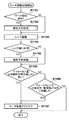
次に図5のS505の焦点状態検出処理について図6を用いて説明する。まず、S601でAF信号処理部204は、任意に設定した焦点検出範囲に含まれる画素からAF用の1対の像信号を取得する。次に、S602でAF信号処理部204は、取得した像信号間の相関量を算出する。続いて、S603でAF信号処理部204はS602より算出した相関量から相関変化量を算出する。そしてS604でAF信号処理部204は相関変化量からピントずれ量を算出する。またS605でAF信号処理部204はピントずれ量がどれだけ信頼できるのかを表す信頼性を算出する。これらの処理を、焦点検出範囲内に存在する焦点検出領域の数だけ行う。そして、S606でAF信号処理部204は焦点検出領域ごとにピントずれ量をデフォーカス量に変換する。最後にAF信号処理部204は、AFに使用する焦点検出領域をS607で決定し、焦点状態検出処理を終了する。
Next, the focus state detection process in S505 of FIG. 5 will be described with reference to FIG. First, in step S601, the AF
図7から図9(b)を用いて図6で説明した焦点状態検出処理をさらに詳細に説明する。
図7は焦点状態検出処理で取り扱う焦点検出範囲と焦点検出領域の一例を模式的に示した図である。
図7(a)は、撮像素子201の画素アレイ1501における焦点検出範囲1502の例を示している。シフト領域1503は、相関演算に必要な領域である。従って、焦点検出範囲1502とシフト領域1503とを合わせた領域1504が相関演算に必要な画素領域である。図中のp、q、s、tはそれぞれx軸方向の座標を表し、pおよびqは画素領域1504の始点及び終点のx座標を、sおよびtは焦点検出範囲1502の始点および終点のx座標を表す。
The focus state detection process described in FIG. 6 will be described in more detail with reference to FIGS. 7 to 9B.
FIG. 7 is a diagram schematically illustrating an example of a focus detection range and a focus detection region handled in the focus state detection process.
FIG. 7A shows an example of a
図7(b)は焦点検出範囲1502を5つの焦点検出領域1505〜1509に分割した例を示す図である。本実施形態ではこのように焦点検出範囲を分割した焦点検出領域ごとにピントずれ量を算出し、最も信頼できるピントずれ量を用いる。
図7(c)は、図7(b)の焦点検出領域1505〜1509を連結した仮の焦点検出領域を示す図である。このように、焦点検出領域を連結した領域から算出したピントずれ量を用いても良い。焦点検出領域の配置の仕方、領域の広さ等は、ここで例示した構成に限られるものではなく、他の構成を用いてもよい。
FIG. 7B is a diagram showing an example in which the
FIG. 7C is a diagram showing a temporary focus detection area in which the
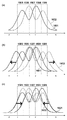
図8は図7で設定した焦点検出領域1505〜1509に含まれる画素から取得したAF用の像信号の例を示している。実線1601が像信号A、破線1602が像信号Bである。
図8(a)は、シフト前の像信号の例を示している。
図8(b)および(c)は、図8(a)のシフト前の像波形に対しプラス方向およびマイナス方向にシフトした状態を示している。相関量を算出する際には、像信号A1601および像信号B1602の両方を、矢印の方向に1ビットずつシフトする。続いて相関量CORの算出法について説明する。
FIG. 8 shows an example of an AF image signal acquired from the pixels included in the
FIG. 8A shows an example of the image signal before the shift.
FIGS. 8B and 8C show a state where the image waveform before the shift in FIG. 8A is shifted in the plus direction and the minus direction. When calculating the correlation amount, both the
まず、図8(b)および(c)に示したように、像信号A1601と像信号B1602のそれぞれを1ビットずつシフトし、その時の像信号Aと像信号Bの差の絶対値の和を算出する。この時、シフト量をiで表し、最小シフト量は図8中のp−s、最大シフト量は図8中のq−tである。またxは焦点検出領域1508の開始座標、yは焦点検出領域1508の終了座標である。これらを用い、焦点検出領域1508における相関量CORは以下の式(1)によって算出することができる。

図9(a)はシフト量と相関量との関係例を示した図である。横軸はシフト量を示し、縦軸は相関量を示す。相関量波形1701における極値付近1702、1703のうち、相関量が小さい方ほど、像信号Aと像信号Bの一致度が高い。続いて相関変化量ΔCORの算出法について説明する。
FIG. 9A shows an example of the relationship between the shift amount and the correlation amount. The horizontal axis indicates the shift amount, and the vertical axis indicates the correlation amount. Of the
まず、図9(a)の相関量波形から、1シフト飛ばしの相関量の差から相関変化量を算出する。シフト量をiで表し、最小シフト量は図8中のp−s、最大シフト量は図8中のq−tである。これらを用い、相関変化量ΔCORは以下の式(2)によって算出することができる。
図10(a)はシフト量と相関変化量ΔCORの関係例を示した図である。横軸はシフト量を示し、縦軸は相関変化量を示す。相関変化量波形1801で、1802、1803は相関変化量がプラスからマイナスになる周辺である。相関変化量が0となる状態ゼロクロスと呼び、像信号間の一致度が最も高く、ゼロクロス時のシフト量がピントずれ量となる。
FIG. 10A shows an example of the relationship between the shift amount and the correlation change amount ΔCOR. The horizontal axis indicates the shift amount, and the vertical axis indicates the correlation change amount. In the correlation
図10(b)は図10(a)の1802の部分を拡大したもので、1901は相関変化量波形1801の一部分である。図10(b)を用いてピントずれ量PRDの算出法について説明する。
ここで、ゼロクロス時のシフト量(k−1+α)は、整数部分β(=k−1)と小数部分αに分けられる。小数部分αは、図中の三角形ABCと三角形ADEの相似の関係から、以下の式(3)によって算出することができる。
β=k−1 (4)
αとβの和からピントずれ量PRDを算出することができる。
FIG. 10B is an enlarged view of the
Here, the shift amount (k−1 + α) at the time of zero crossing is divided into an integer part β (= k−1) and a decimal part α. The decimal part α can be calculated by the following equation (3) from the similar relationship between the triangle ABC and the triangle ADE in the figure.
β = k−1 (4)
The focus shift amount PRD can be calculated from the sum of α and β.
また図10(a)のようにゼロクロスとなるシフト量が複数が存在する場合は、ゼロクロスでの相関量変化の急峻性が大きいところを第1のゼロクロスとする。この急峻性はAFのし易さを示す指標で、値が大きいほどAFし易い点であることを示す。急峻性maxderは以下の式(5)によって算出することができる。
![]()
![]()
信頼性は、上述した急峻性や、像信号A、Bの一致度fnclvl(以下、2像一致度と呼ぶ)によって定義することができる。2像一致度はピントずれ量の精度を表す指標で、値が小さいほど精度が良い。
図9(b)は図9(a)の1702の部分を拡大したもので、2001が相関量波形1701の一部分である。図9(b)を用いて急峻性と2像一致度の算出法について説明する。
2像一致度fnclvlは以下の式(6)によって算出できる。
FIG. 9B is an enlarged view of the
The two-image coincidence degree fnclvl can be calculated by the following equation (6).
次に図5のS508のAF再起動判定について図11のフローチャートを用いて説明する。AF再起動判定は、合焦していると判断してフォーカスレンズ103を停止している際に、再度フォーカスレンズ103を駆動するかどうかの判定をする処理である。
S701でカメラ制御部212は、AF信号処理部204が算出したデフォーカス量が焦点深度の所定倍(ここでは1倍とする)より小さいかどうかを判断し、小さい場合はS702へ、大きい場合はS704へ処理を進める。S702でカメラ制御部212は、AF信号処理部204が算出した信頼性が所定値より良いかどうかを判断し、良い値を示す場合はS703へ処理を進め、そうでない場合はS704へ処理を進める。S703でカメラ制御部212は、AF再起動カウンタをリセットし、S705へ処理を進める。S704でカメラ制御部212は、AF再起動カウンタを加算しS705へ処理を進める。
Next, the AF restart determination in S508 of FIG. 5 will be described using the flowchart of FIG. The AF restart determination is a process for determining whether to drive the
In step S701, the
上述したように、デフォーカス量が所定量以上、またはデフォーカス量の信頼性が所定値より悪い場合、カメラ制御部212は、撮影している主被写体が変わったと判断し、AF再起動をする(フォーカスレンズ103を再駆動する)準備を行う。一方、デフォーカス量の大きさと信頼性から、主被写体が変わっていないと判断する場合、AF再起動をしない(フォーカスレンズ103の停止状態を維持する)ようにする。
As described above, when the defocus amount is greater than or equal to the predetermined amount or the reliability of the defocus amount is worse than the predetermined value, the
S701で設定するデフォーカス量の閾値は、主被写体が変わったときにはAF再起動が行われ、主被写体が変わっていないときにはAF再起動がされにくくなるよう、経験的もしくは実験的に設定する。また、S702で設定する信頼性の閾値は、例えばデフォーカス方向を信頼するのが困難なほど低い信頼性の場合にAF再起動されるように設定する。このようにS701、S702の判定は、主被写体が変わったかどうかの判定処理とも言える。従って、同様の判定が可能な任意の処理に置き換えることができ、処理の方法に応じて用いる閾値の種類や値を設定する。 The threshold value of the defocus amount set in S701 is set empirically or experimentally so that AF restart is performed when the main subject is changed, and AF restart is difficult when the main subject is not changed. Further, the reliability threshold value set in S702 is set such that AF restart is performed when the reliability is so low that it is difficult to trust the defocus direction, for example. As described above, the determinations in S701 and S702 can be said to be determination processing for determining whether or not the main subject has changed. Therefore, it can be replaced with an arbitrary process capable of the same determination, and the type and value of the threshold used according to the processing method are set.
S705でカメラ制御部212は、AF再起動カウンタの値が所定値より大きいかどうかを判断し、所定値より大きい場合はS706へ処理を進め、小さい場合はAF再起動判定処理を終了する。S706でカメラ制御部212は、合焦停止フラグをオフにすることでAFの再起動を行い、AF再起動判定処理を終了する。S706でAF再起動を決定するに当たってカメラ制御部212は、S704で加算したAF再起動カウンタの値が、所定値より大きいかどうかをS705で判断する。AF再起動カウンタの加算と値の判定は、主被写体が変化したかどうかの判定を、デフォーカス量の大きさや信頼性の1回の判定に基づいて行わず、一定期間に得られる判定結果の統計量に基づいて行うものである。このようにすることで、主被写体が実際には変わっていないにもかかわらず、ごく一時的なデフォーカス量の大きさや信頼性の変動によって主被写体が変わったと判断してAF再起動することによる画質への影響を防ぐ。
In step S705, the
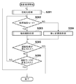
次に図5のS507のAF処理について図12のフローチャートを用いて説明する。AF処理は、合焦停止していない状態でのフォーカスレンズの駆動及び、合焦停止の判定を行う処理である。
S801でカメラ制御部212は、デフォーカス量の大きさが予め定めた量以下(ここでは焦点深度内とする)であり、かつデフォーカス量の信頼性が所定値より良い値を示しているかどうかを判断する。そして、カメラ制御部212は、この条件に該当する場合はS802へ処理を進め、そうでない場合はS803へ処理を進める。本実施形態では、S801で用いる閾値を焦点深度の1倍としているが、必要に応じて大きく設定したり、小さく設定したりしても構わない。S801で設定する信頼性の閾値は、少なくとも合焦精度が保証できる様な値を設定する。
Next, the AF process in S507 of FIG. 5 will be described using the flowchart of FIG. The AF processing is processing for driving the focus lens in a state where focusing is not stopped and for determining whether focusing is stopped.
In step S <b> 801, the
S802でカメラ制御部212は、被写体に合焦したとしてフォーカスレンズの駆動を停止するかどうかを判定する合焦停止判定処理を行い、AF処理を終了する。S802の合焦停止判定処理の中で、カメラ制御部212は合焦停止フラグをオンにするかオフのままとするかを判定する。合焦停止判定処理の詳細は図17を用いて後述する。
In step S <b> 802, the
S801でデフォーカス量が焦点深度内でない、またはデフォーカス量の信頼性が所定値より悪い場合に進むS803でカメラ制御部212は合焦停止判定カウンタをリセットして処理をS804に進める。合焦停止判定カウンタは、後述するS802の合焦停止判定処理で、フォーカスレンズの駆動を停止するか否かを判断するために用いるためのデータである。デフォーカス量が焦点深度内でないか、またはデフォーカス量の信頼性が所定値より悪い場合は、その後すぐに合焦停止判定を行わないように合焦停止判定カウンタをリセットする。
If the defocus amount is not within the depth of focus in S801 or if the reliability of the defocus amount is worse than the predetermined value, the
S804でカメラ制御部212は、フォーカスレンズの駆動速度や駆動方法を決定し、設定する。詳細は図13を用いて後述する。S804でレンズ駆動設定を行った後に進むS805でカメラ制御部212は、レンズ駆動処理を実施しAF処理を終了する。S805のレンズ駆動処理の詳細は図14を用いて後述する。
In step S804, the
次に図12のS804のレンズ駆動設定について図13のフローチャートを用いて説明する。本実施形態におけるレンズ駆動設定では、デフォーカス量の信頼性に応じたフォーカスレンズの駆動速度を設定する。
S901からS907では、レンズ駆動速度の設定及び、サーチ駆動移行カウンタの加算及びリセットを行う。S901では信頼性が所定値αより良い値か(信頼性が所定の信頼性より高いか)どうかを判断し、所定値αより良い値の場合はS902へ処理を進め、そうでない場合はS904へ処理を進める。S902でカメラ制御部212は、サーチ駆動カウンタをリセットしてS903へ処理を進め、レンズ駆動速度Aを設定して処理をS908へ進める。
Next, the lens drive setting in S804 of FIG. 12 will be described using the flowchart of FIG. In the lens driving setting in the present embodiment, the driving speed of the focus lens is set according to the reliability of the defocus amount.
In steps S901 to S907, the lens drive speed is set, and the search drive transition counter is added and reset. In S901, it is determined whether or not the reliability is better than the predetermined value α (whether the reliability is higher than the predetermined reliability). If the reliability is higher than the predetermined value α, the process proceeds to S902. If not, the process proceeds to S904. Proceed with the process. In step S902, the
S901で信頼性が所定値αより良い値でない(信頼性が所定の信頼性より高くない)場合に進むS904でカメラ制御部212は、サーチ駆動移行カウンタを加算してS905に処理を進める。S905でカメラ制御部212は、サーチ駆動移行カウンタの値が所定値以上かどうかを判断し、所定値以上である場合はS906へ、所定値以上でない場合はS907へ処理を進める。S905でサーチ駆動移行カウンタの値が所定値以上であると判断した場合に進むS906でカメラ制御部212は、サーチ駆動フラグをオンにしてS908へ処理を進める。一方、S905でサーチ駆動移行カウンタの値が所定値以上でないと判断された場合に進むS907でカメラ制御部212は、フォーカスレンズの駆動速度Zを設定して処理をS908へ進める。S903、S906、S907のいずれかの後に行うS908でカメラ制御部212は、サーチ駆動フラグがオンかどうかを判断し、オンである場合はS909へ処理を進め、オフである場合はレンズ駆動設定処理を終了する。S908でサーチ駆動フラグがオンだと判断した後に進むS909でカメラ制御部212は、レンズ駆動速度Sを設定し、レンズ駆動設定処理を終了する。
When the reliability is not better than the predetermined value α in S901 (the reliability is not higher than the predetermined reliability), in S904, the
S901で設定する信頼性閾値αは、デフォーカスの方向と量のうち、少なくとも方向が信頼できると判定できる値に設定する。デフォーカス方向が信頼できる場合は、設定したレンズ駆動速度Aでデフォーカス量を基にフォーカスレンズを駆動するようにする。一方、デフォーカス方向が信頼できないと判定される信頼性(αより悪い)が継続している場合は、サーチ駆動を行う。サーチ駆動とはデフォーカス量に関係なく、デフォーカス方向を設定してその方向に所定単位(ステップ駆動量)ずつ、フォーカスレンズをその駆動範囲内で駆動する方法である。 The reliability threshold value α set in S901 is set to a value at which at least the direction can be determined to be reliable out of the defocus direction and amount. When the defocus direction is reliable, the focus lens is driven based on the defocus amount at the set lens driving speed A. On the other hand, when the reliability that is determined that the defocus direction is not reliable (which is worse than α) continues, search driving is performed. Search drive is a method of setting the defocus direction and driving the focus lens within the drive range by a predetermined unit (step drive amount) in that direction regardless of the defocus amount.
S901で、デフォーカス量の方向も信頼できない場合にはS904でサーチ駆動移行カウンタを加算し、S905でサーチ駆動移行カウンタの値が所定値以上になったかどうかを判定することで、継続して信頼性が低い状態である場合にのみサーチ駆動を行う。上述の通りサーチ駆動はデフォーカス量を使用しないため、一時的に大きくボケてしまうような品位の悪いフォーカスレンズの駆動を行う可能性がある。そこで、信頼性が低くなってもすぐにサーチ駆動に移行させないようにすることで、ノイズ等の一時的な要因によって不用意にサーチ駆動をしないようにしている。 If the direction of the defocus amount is also unreliable in S901, the search drive transition counter is added in S904, and it is determined whether or not the value of the search drive transition counter is equal to or greater than a predetermined value in S905. Search drive is performed only when the state is low. As described above, since the search drive does not use the defocus amount, there is a possibility of driving a poor-quality focus lens that temporarily becomes largely blurred. Therefore, even if the reliability is lowered, the search drive is not immediately shifted to prevent the search drive from being inadvertently caused by temporary factors such as noise.
S905でサーチ駆動移行カウンタの値が所定値以上となり、サーチ駆動に移行することを判断すると、カメラ制御部212はS906でサーチ駆動フラグをオンにし、S908を経てS909でサーチ駆動用のレンズ駆動速度Sを設定する。サーチ駆動速度Sには、駆動速度Aよりも速い値を設定する。サーチ駆動移行カウンタが所定値に達する前にデフォーカス量の信頼性が所定値αより良い値になった場合、カメラ制御部212はS902でサーチ駆動移行カウンタをリセットする。また、デフォーカス量の信頼度が所定値αより悪いが、サーチ駆動移行カウンタの値が所定値に達していない場合に進むS907で設定するレンズ駆動速度Zには、駆動速度Aより遅い、かつ十分に遅い(ゼロを含む)値を設定する。
When it is determined in S905 that the value of the search drive shift counter becomes equal to or greater than the predetermined value and shifts to search drive, the
図13において設定するレンズ駆動速度には以下の関係がある。
Z < A < S (Zが最も遅く、Sが最も速い)
サーチ駆動を行うのはデフォーカス量の信頼性がデフォーカス方向も信頼できない低い状態が継続している場合であるため、主被写体は大きくボケていると考えられる。そのため、素早く合焦できるよう、S909で設定するサーチ駆動時のフォーカスレンズ駆動速度Sは、駆動速度Aよりも速い値とする。
The lens driving speed set in FIG. 13 has the following relationship.
Z <A <S (Z is the slowest, S is the fastest)
Search driving is performed when the reliability of the defocus amount is low and the defocus direction is unreliable, and the main subject is considered to be greatly blurred. For this reason, the focus lens driving speed S at the time of search driving set in S909 is set to a value faster than the driving speed A so that focusing can be performed quickly.
また、S901で信頼性が所定値αより悪く、S905でサーチ駆動に移行するか判断する間は、デフォーカス量を信じてフォーカスレンズ駆動させない方が良い。そのため、S907でカメラ制御部212は、フォーカスレンズの駆動速度Zとして、速度0(停止)もしくは駆動が目立たない程度の低い速度を設定する。これにより、デフォーカス量の信頼性が悪い場合に品位の悪いフォーカスレンズ駆動がなされることを防止している。
In S901, the reliability is lower than the predetermined value α, and it is better not to drive the focus lens by believing in the defocus amount while determining whether to shift to search driving in S905. Therefore, in S907, the
次に図12のS805のレンズ駆動処理について図14のフローチャートを用いて説明する。レンズ駆動処理は、図13を用いて説明したレンズ駆動設定処理によって設定した駆動速度や、サーチ駆動フラグなどの設定を基にフォーカスレンズ103を駆動する処理である。
S1001でカメラ制御部212は、サーチ駆動フラグがオフかどうかを判断し、オフの場合はS1002へ処理を進め、デフォーカス量を基に、レンズ駆動設定処理によって設定した駆動速度でフォーカスレンズを駆動し、レンズ駆動処理を終了する。また、サーチ駆動フラグがオンの場合はS1003へ処理を進め、サーチ駆動処理を行いレンズ駆動処理を終了する。S1003のサーチ駆動処理の詳細は図15を用いて後述する。
Next, the lens driving process in S805 of FIG. 12 will be described using the flowchart of FIG. The lens driving process is a process for driving the
In step S1001, the
次に図14のS1003のサーチ駆動処理について図15のフローチャートを用いて説明する。サーチ駆動処理は、図13のS906でサーチ駆動フラグがオンされた場合に行う処理であり、フォーカスレンズの駆動範囲内を、S909で設定された駆動速度で駆動する。 Next, the search drive processing in S1003 of FIG. 14 will be described using the flowchart of FIG. The search drive process is a process that is performed when the search drive flag is turned on in S906 of FIG. 13, and the focus lens drive range is driven at the drive speed set in S909.
S1101でカメラ制御部212は、サーチ駆動が初回かどうかを判断し、初回でない場合はS1103へ直接処理を進め、初回である場合はS1102で駆動方向設定を行ってからS1103へ処理を進める。サーチ駆動が初回である場合は、どちらにフォーカスレンズ103を駆動するかを決定する必要がある。S1102の駆動方向設定処理については図16を用いて後述する。
In step S1101, the
S1103でカメラ制御部212は、レンズ制御部106を通じ、設定した駆動方向及び駆動速度Sでフォーカスレンズ103を駆動し、S1104へ処理を進める。S1104でカメラ制御部212は、フォーカスレンズ103が至近端若しくは無限端に到達したかどうかを判断し、到達した場合はS1105へ処理を進め、到達していない場合はS1106へ処理を進める。S1105でカメラ制御部212は、駆動方向を反転させてS1106へ処理を進める。S1106でカメラ制御部212は、信頼性が所定値αより良い値かどうかを判断し、所定値αより良い値の場合はS1107へ処理を進め、そうでない場合はS1108へ処理を進める。S1108でカメラ制御部212は、フォーカスレンズ103がサーチ駆動の過程で至近端、無限端の両方に到達したかどうかを判断し、到達した場合はS1107へ処理を進め、到達していない場合はサーチ駆動処理を終了する。S1107でカメラ制御部212は、サーチ駆動フラグをオフにしてサーチ駆動処理を終了する。
In step S <b> 1103, the
サーチ駆動を終了する条件は、S1106で信頼性が所定値αより良い値になった場合、若しくはS1108でフォーカスレンズ103が至近端、無限端の両方に到達した場合である。S1106で設定する信頼性閾値αは、図13のS901で設定した閾値αと同じであり、少なくともデフォーカス量の方向が信頼できると判断できる値である。信頼性が閾値αより良い値になったのであれば、被写体が合焦に近づいてきたと判断できるため、サーチ駆動をやめて再度デフォーカス量を基に駆動する制御に切り替える。また、S1108で至近端、無限端の両方に到達したと判断された場合は、フォーカス駆動範囲の全域を駆動した場合であり、つまりは被写体が特定できなかった場合である。この場合はサーチ駆動フラグをオフにし、最初の処理の状態に戻す。なお、被写体が特定できない場合にはサーチ駆動フラグをオフにせずにサーチ駆動を継続させるようにしても良い。
The conditions for terminating the search drive are when the reliability becomes better than the predetermined value α in S1106, or when the
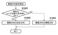
次に図15のS1102の駆動方向設定処理について、図16のフローチャートを用いて説明する。S1201でカメラ制御部212は、フォーカスレンズ103の現在位置が無限端よりも至近端に近いかどうかを判断し、至近端に近い場合はS1202へ処理を進め、無限端に近い場合はS1203へ処理を進める。
Next, the drive direction setting process in S1102 of FIG. 15 will be described using the flowchart of FIG. In step S1201, the
S1202でカメラ制御部212は、サーチ駆動開始時のフォーカスレンズ103の駆動方向を至近方向に設定して駆動方向設定処理を終了する。一方、S1203でカメラ制御部212は、サーチ駆動開始時のフォーカスレンズ103の駆動方向を無限方向に設定して駆動方向設定処理を終了する。このように駆動方向を設定することで、フォーカスレンズの駆動領域全体をサーチ駆動する時間を短縮することができ、サーチ駆動によって被写体を発見するために要する最大時間を短くできる。
In step S1202, the
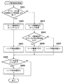
次に、図12のS802で行う合焦停止判定処理について、図17に示すフローチャートを用いて説明する。
S1301でカメラ制御部212(合焦停止判定部213)は、フォーカスレンズの駆動を停止するか否かを判定するために用いられる合焦停止閾値を設定してS1302へ処理を進める。S1301の合焦停止閾値設定処理の詳細は図18を用いて後述する。
Next, the focus stop determination process performed in S802 of FIG. 12 will be described using the flowchart shown in FIG.
In step S1301, the camera control unit 212 (focus stop determination unit 213) sets a focus stop threshold used to determine whether to stop driving the focus lens, and advances the process to step S1302. Details of the focus stop threshold value setting process in S1301 will be described later with reference to FIG.
S1302で合焦停止判定部213は、合焦停止カウンタの値に1を加算して処理をS1303へ進める。S1303で合焦停止判定部213は、合焦停止カウンタの値がS1301で設定した合焦停止閾値以上かどうかを判断して、合焦停止閾値以上であればS1304へ、合焦停止閾値未満であれば処理を終了する。S1304で合焦停止判定部213は、合焦停止フラグをオンにして処理を終了する。
In step S1302, the focus
S1301で合焦停止閾値として設定する値については図18で後述するが、図17の説明においては、合焦停止閾値として2以上の値を設定したものとして説明を行う。この2以上という値は、本実施形態において図18のS1404で設定する合焦停止閾値Yに該当する。なお、本実施形態において合焦停止閾値は、デフォーカス量の信頼性がαより良いと連続して判定された回数の閾値である。 The value set as the focus stop threshold value in S1301 will be described later with reference to FIG. 18, but in the description of FIG. 17, it is assumed that a value of 2 or more is set as the focus stop threshold value. The value of 2 or more corresponds to the focus stop threshold Y set in S1404 of FIG. 18 in the present embodiment. In the present embodiment, the focus stop threshold is a threshold of the number of times that the defocus amount reliability is continuously determined to be better than α.
先述したように、動画AF制御において、被写体に合焦したと判断された際にフォーカスレンズの駆動を停止するのは一時的な要因による不要な合焦度合いの変動を抑制するためである。しかし、図19(a)を用いて説明したように、距離が徐々に変化している被写体の追従中に合焦したと判断してフォーカスレンズを停止してしまうと、図5のS508の再起動判定処理で再起動という判定がされるまでフォーカスレンズが駆動されない。再起動が決定されるまでの間は被写体のボケが徐々に大きくなり、再起動が決定されてフォーカスレンズが再駆動されると被写体に合焦するが、再度合焦判定によってフォーカスレンズの駆動が停止される。そうすると、図19(a)に示したように、フォーカスレンズの駆動、停止、再起動が繰り返され、被写体にピントが合ってはボケるという挙動を繰り返す動画像が撮影されてしまう。 As described above, in the moving image AF control, the driving of the focus lens is stopped when it is determined that the subject is in focus, in order to suppress unnecessary fluctuation of the focus level due to a temporary factor. However, as described with reference to FIG. 19A, if it is determined that the subject is in focus while following the subject whose distance is gradually changing and the focus lens is stopped, the process of S508 in FIG. The focus lens is not driven until it is determined to restart in the startup determination process. Until the restart is determined, the subject's blur gradually increases, and when the restart is determined and the focus lens is redriven, the subject is focused. Stopped. As a result, as shown in FIG. 19A, the focus lens is repeatedly driven, stopped, and restarted, and a moving image that repeats the behavior of being out of focus when the subject is in focus is captured.
そのため、本実施形態では、デフォーカス量が焦点深度内であり、デフォーカス量の信頼性が所定値より良い場合であっても、直ちに合焦と判定してフォーカスレンズの駆動を停止することはせず、フォーカスレンズの駆動を継続する。そして、デフォーカス量が焦点深度内であり、デフォーカス量の信頼性が所定値より良いという判定が所定の複数回連続した場合に、フォーカスレンズの駆動を停止するようにした。なお、信頼性が所定値より良いかどうかは必須ではなく、デフォーカス深度が焦点深度内かどうかだけを判定するようにしてもよい。 Therefore, in this embodiment, even when the defocus amount is within the depth of focus and the reliability of the defocus amount is better than a predetermined value, it is determined that the in-focus state is satisfied and the driving of the focus lens is stopped immediately. Without continuing, the focus lens continues to be driven. Then, when the determination that the defocus amount is within the depth of focus and the reliability of the defocus amount is better than a predetermined value continues for a predetermined number of times, the driving of the focus lens is stopped. Note that it is not essential whether the reliability is better than a predetermined value, and it may be determined only whether the defocus depth is within the focal depth.
距離が徐々に変化している被写体であれば、ある時点でデフォーカス量が焦点深度内となっても、時間の経過とともにデフォーカス量が焦点深度から外れていく。そのため、所定の複数回連続してデフォーカス量が焦点深度内である場合に初めて被写体の距離が安定している(合焦している)と判定し、フォーカスレンズの駆動を停止する。 If the subject has a gradually changing distance, even if the defocus amount falls within the depth of focus at a certain point in time, the defocus amount deviates from the depth of focus over time. Therefore, it is determined that the distance to the subject is stable (focused) for the first time only when the defocus amount is within the depth of focus continuously for a predetermined number of times, and driving of the focus lens is stopped.
つまり、図12のS801でデフォーカス量が焦点深度内でなければ、S803で合焦停止カウンタがリセットされる。そのため、デフォーカス量が焦点深度内に入っても、合焦停止カウンタの値が合焦停止閾値に達する前にデフォーカス量が焦点深度から外れる(または、デフォーカス量の信頼性が所定値より悪くなる)と、合焦停止カウンタはリセットされる。この間、フォーカスレンズの駆動は継続しているため、被写体の距離が変化している場合でも、最新の被写体距離に追従したフォーカスレンズの駆動が実現できる。従って、図19(a)に示したような被写体に対しても、図19(b)のように滑らかにかつ被写体距離に追従してフォーカスレンズを駆動することができるため、撮影される動画像の合焦度合いを大きく変動させることがない。 That is, if the defocus amount is not within the depth of focus in S801 of FIG. 12, the focus stop counter is reset in S803. Therefore, even if the defocus amount falls within the depth of focus, the defocus amount deviates from the focus depth before the value of the focus stop counter reaches the focus stop threshold (or the reliability of the defocus amount exceeds the predetermined value). When it gets worse), the focus stop counter is reset. During this time, since the focus lens continues to be driven, the focus lens can be driven to follow the latest subject distance even when the subject distance changes. Accordingly, even for a subject as shown in FIG. 19A, the focus lens can be driven smoothly and following the subject distance as shown in FIG. The in-focus level is not greatly changed.
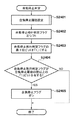
次に、図17のS1301における合焦停止閾値設定処理について、図18のフローチャートを用いて説明する。S1401でカメラ制御部212(合焦停止判定部213)は、図6のS607で設定した焦点検出領域(AF枠)の像高が所定値より大きいかどうかを判断する。そして、合焦停止判定部213は、焦点検出領域の像高が所定値より大きいと判断される場合はS1402へ、所定値以下と判断される場合にはS1403へ処理を進める。
Next, the focus stop threshold value setting process in S1301 of FIG. 17 will be described using the flowchart of FIG. In step S1401, the camera control unit 212 (focus stop determination unit 213) determines whether the image height of the focus detection area (AF frame) set in step S607 in FIG. 6 is greater than a predetermined value. The focus
S1403で合焦停止判定部213は設定されている絞り値が所定値より小絞り側か(所定値より大きいか)どうかを判断し、小絞り側と判断される場合はS1402へ、そうでないと判断される場合はS1404へ処理を進める。S1402で合焦停止判定部213は、合焦停止閾値をXに設定し処理を終了する。S1404で合焦停止判定部213は合焦停止閾値をY(Y>X)に設定し処理を終了する。
In step S1403, the focus
図17の説明において、合焦停止閾値を2以上に設定すると述べたが、これはS1404で合焦停止閾値に設定されるYを想定している。合焦停止閾値を2以上(の整数)に設定することで、図17のS1303で、焦点深度内のデフォーカス量が連続して観測されている場合にのみ合焦停止させることができる。 In the description of FIG. 17, it has been described that the focus stop threshold value is set to 2 or more, but this assumes Y that is set as the focus stop threshold value in S1404. By setting the focus stop threshold to 2 or more (an integer thereof), focus stop can be performed only when the defocus amount within the depth of focus is continuously observed in S1303 of FIG.
ただし、本実施形態では、デフォーカス検出精度が悪くなる設定で撮影されている場合には、合焦停止閾値をS1402でX(X<Y)に設定する。ここでは、デフォーカス検出精度が悪くなる設定の例として、(1)焦点検出領域の像高が大きい場合、(2)絞り値が大きい(小絞りである)場合を示している。 However, in the present embodiment, when the image is shot with a setting that causes the defocus detection accuracy to deteriorate, the focus stop threshold is set to X (X <Y) in S1402. Here, as an example of the setting that the defocus detection accuracy deteriorates, (1) when the image height of the focus detection area is large, (2) when the aperture value is large (small aperture) is shown.
撮像面位相差検出方式では、一般的に像高が大きいほど像信号A、Bを取得する瞳A、Bに入射する光量差が大きくなり、瞳内の位置によって瞳強度が異なるという特性がある。そのため、像高が大きい位置では像信号A、B間のレベル差が顕著に表れ、像信号A、Bの像一致度が低下し、デフォーカス検出精度が低下してしまう。 The imaging surface phase difference detection method generally has a characteristic that the larger the image height, the greater the difference in the amount of light incident on the pupils A and B that acquire the image signals A and B, and the pupil intensity varies depending on the position in the pupil. . Therefore, the level difference between the image signals A and B appears remarkably at a position where the image height is large, the image coincidence between the image signals A and B is lowered, and the defocus detection accuracy is lowered.
また、撮像面位相差検出方式では、絞り値が大きい(小絞り)ほど、像信号A、Bを結像する基線長が短くなるため、像信号A、Bの像ずれ量をデフォーカス量に換算する換算係数が大きくなる特性がある。そのため、絞り値が大きい(小絞り)ほど、少しの像ずれ量が大きなデフォーカス量に換算され、デフォーカス精度が悪化する。 In the imaging surface phase difference detection method, the larger the aperture value (small aperture), the shorter the baseline length for imaging the image signals A and B. Therefore, the image shift amount of the image signals A and B is set to the defocus amount. There is a characteristic that the conversion factor to be converted becomes large. Therefore, the larger the aperture value (small aperture), the smaller the image shift amount is converted into a larger defocus amount, and the defocus accuracy is deteriorated.
本実施形態ではS1402で合焦停止閾値に設定するXを1とする。これは、デフォーカス検出精度が悪い条件では、被写体の距離が変化しない場合であっても、S801におけるデフォーカス量とその信頼性の条件を連続して満たすことが困難となり得るからである。デフォーカス検出精度が悪い条件で合焦停止閾値を大きく設定すると、被写体距離が変化していないにもかかわらず、合焦との判断が行われず、フォーカスレンズの駆動が継続されるため、ハンチングを繰り返してしまう。そのため、本実施形態では、デフォーカス検出精度(信頼性)が低くなりやすい条件が設定されている場合には、1回でもデフォーカス量が焦点深度内で、信頼性が所定値より良くなれば、すぐに合焦と判断してフォーカスレンズの駆動を停止させる。なお、ここでは一例としてXを1、Yを2以上と説明したが、X<Yの関係であれば他の任意の値の組み合わせであってよい。 In the present embodiment, X set to the focus stop threshold value in S1402 is set to 1. This is because, under conditions where the defocus detection accuracy is poor, it may be difficult to continuously satisfy the defocus amount and the reliability conditions in S801 even when the distance of the subject does not change. If the focus stop threshold is set to a large value under conditions where the defocus detection accuracy is poor, the focus lens will not be determined even though the subject distance has not changed, and the focus lens will continue to be driven. It repeats. For this reason, in the present embodiment, when the condition that the defocus detection accuracy (reliability) tends to be low is set, if the defocus amount is within the depth of focus and the reliability is better than a predetermined value even once. Immediately, the focus lens is determined to be in focus and the driving of the focus lens is stopped. Here, as an example, X is 1 and Y is 2 or more, but any other combination of values may be used as long as X <Y.
なお、デフォーカス検出精度(信頼性)が低くなりやすい条件の例として、絞り値と像高を説明したが、さらに、あるいはこれらに代えて、他の条件を考慮しても良い。例えば、絞り値の代わりに変換係数の値が所定値以上であることを条件として用いても良い。これは、上述の通り、絞り値の大きさと変換係数の大きさとが連動しているためである。同様に、変換係数の大きさの変化と連動した大きさを有する他のパラメータを用いることもできる。また、変換係数や像高とは独立したパラメータを考慮することもできる。 Note that the aperture value and the image height have been described as examples of conditions under which defocus detection accuracy (reliability) tends to be low, but other conditions may be considered in addition to or instead of these. For example, instead of the aperture value, the condition that the value of the conversion coefficient is a predetermined value or more may be used as a condition. This is because the size of the aperture value and the size of the conversion coefficient are linked as described above. Similarly, other parameters having a magnitude linked to a change in the magnitude of the transform coefficient can be used. In addition, parameters independent of the conversion coefficient and the image height can be considered.
なお、S801においてはデフォーカス量とその信頼性の両方が条件を満たすかどうか判定しているが、デフォーカス検出精度が悪くなる設定がなされている場合には、デフォーカス深度が焦点深度内かどうかだけを判定するように変形してもよい。この場合、S801の前にS1401およびS1403と同様の判定を行い、いずれかが満たされれば、S801ではデフォーカス量の判定のみを行うようにすればよい。 In S801, it is determined whether both the defocus amount and its reliability satisfy the condition. If the defocus detection accuracy is set to deteriorate, is the defocus depth within the focus depth? It may be modified so as to determine only whether or not. In this case, the same determination as S1401 and S1403 is performed before S801, and if either of them is satisfied, only the determination of the defocus amount may be performed in S801.
また、静止画撮影時のAF制御の場合は、合焦までの時間が短いことが重視されるため、合焦精度が保証される範囲(深度の所定倍)内のデフォーカス量を検出した段階で、フォーカスレンズの駆動後すぐにフォーカスレンズの駆動を停止させる。 In the case of AF control during still image shooting, since it is important that the time until focusing is short, the stage of detecting the defocus amount within a range in which focusing accuracy is guaranteed (a predetermined multiple of the depth). Thus, the drive of the focus lens is stopped immediately after the focus lens is driven.
以上説明したように、本実施形態では、焦点深度内のデフォーカス量が検出された時点で直ちに合焦と判断してフォーカスレンズの駆動を停止するのではなく、焦点深度内のデフォーカス量が連続して所定回数以上検出されるとフォーカスレンズの駆動を停止する。これにより、距離が徐々に変化している被写体を動画撮影している場合でも、撮影される画像の合焦状態を大きく変動させることなく、かつ滑らかに被写体距離に追従した焦点検出、つまり品位のよいフォーカスレンズの駆動が可能となる。 As described above, in the present embodiment, when the defocus amount within the depth of focus is detected, it is determined that the focus is in focus immediately, and driving of the focus lens is not stopped, but the defocus amount within the depth of focus is determined. When it is continuously detected a predetermined number of times or more, the driving of the focus lens is stopped. As a result, even when shooting a subject whose distance is gradually changing, focus detection that smoothly follows the subject distance without changing the focus state of the captured image greatly, that is, quality A good focus lens can be driven.
また、撮像面位相差検出方式を用いる場合にデフォーカス検出精度が悪化する設定がなされている場合には、そのような設定がなされていない場合よりも、フォーカスレンズの駆動を停止するための条件を緩く設定する。このようにすることで、被写体との距離が変動していないにもかかわらず、フォーカスレンズの駆動を停止できなくなることを防止できる。 In addition, when the imaging surface phase difference detection method is used, if the defocus detection accuracy is set to deteriorate, the condition for stopping the driving of the focus lens is compared to the case where such setting is not made. Set loosely. In this way, it is possible to prevent the focus lens from being unable to stop driving even though the distance to the subject has not changed.
(第2の実施形態)
以下、本発明の第2の実施形態について説明する。まず本実施形態と第1の実施形態との違いについて説明する。
第1の実施形態では、焦点深度内のデフォーカス量を連続で所定回数検出した場合にフォーカスレンズの駆動を停止した。第2の実施形態では、連続した所定の複数回のデフォーカス量検出により、焦点深度内のデフォーカス量を(所定の複数回以下の)複数回以上検出していればフォーカスレンズの駆動を停止するように制御する。
(Second Embodiment)
Hereinafter, a second embodiment of the present invention will be described. First, differences between the present embodiment and the first embodiment will be described.
In the first embodiment, the driving of the focus lens is stopped when the defocus amount within the depth of focus is continuously detected a predetermined number of times. In the second embodiment, if the defocus amount within the depth of focus is detected a plurality of times (not more than a predetermined number of times) by a plurality of consecutive predetermined defocus amount detections, the driving of the focus lens is stopped. Control to do.
本実施形態におけるレンズ及びカメラ本体からなるレンズ交換式カメラの構成は、第1の実施形態で図1を基に説明した構成と同様なので説明は省略する。
また第1の実施形態で図3〜6および図11〜18のフローチャートを用いて説明したカメラ本体20の動作は、本実施形態においても同様であるため説明を省略する。
Since the configuration of the interchangeable lens camera including the lens and the camera body in the present embodiment is the same as that described in the first embodiment with reference to FIG.
Since the operation of the
まず、図5のS507のAF処理について、図20のフローチャートを用いて説明する。図20のS2301、S2304、S2305の処理は、第1の実施形態における図12のS801、S804、S805の処理と同様なので説明を省略する。S2301で、デフォーカス量が焦点深度内でかつデフォーカス量の信頼性が所定値より良いと判断された場合に実行するS2302でカメラ制御部212(合焦停止判定部213)は、合焦停止判定を行いAF処理を終了する。合焦停止判定処理の詳細は図21を用いて後述する。S2301でデフォーカス量が焦点深度内でない、またはデフォーカス量の信頼性が所定値より悪い場合と判定された場合に実行するS2303でカメラ制御部212は、合焦停止移行判定フラグを左シフトしてS2304へ処理を進める。第1の実施形態では、合焦停止判定カウンタを用いて合焦停止判定を行っていたが、本実施形態では合焦停止移行判定フラグを用いる。
First, the AF processing in S507 of FIG. 5 will be described using the flowchart of FIG. The processes in S2301, S2304, and S2305 in FIG. 20 are the same as the processes in S801, S804, and S805 in FIG. In S2301, the camera control unit 212 (focus stop determination unit 213) executes focus stop in S2302, which is executed when it is determined that the defocus amount is within the depth of focus and the reliability of the defocus amount is better than a predetermined value. A determination is made and the AF process is terminated. Details of the focus stop determination process will be described later with reference to FIG. The
次に、図20のS2302で行う合焦停止判定処理の詳細について、図21のフローチャートを用いて説明する。
図21のS2401、S2405は、図17のS1301、S1304の処理と同様なので説明を省略する。S2401で合焦停止閾値を設定した後に実行するS2402で合焦停止判定部213は、合焦停止移行判定フラグを左シフトして処理をS2403へ進める。S2403で合焦停止判定部213は、合焦停止移行判定フラグの最下位ビットを1にして処理をS2404へ進める。S2404で合焦停止判定部213は、合焦停止移行判定フラグがS2401で設定した合焦停止閾値の数以上「1」のビットを有するかどうか判断し、有すると判断した場合はS2405で合焦停止フラグを1にして合焦停止判定処理を終了する。合焦停止移行判定フラグに含まれる「1」のビット数が合焦停止閾値未満であると判断した場合、合焦停止判定部213は、S2405を実行せずに合焦停止判定処理を終了する。なお、S2404の判定は、合焦停止移行判定フラグの総ビット数に対する「1」ビットの割合や確率が所定値以上かどうかの判定や、焦点深度以内のデフォーカス量が検出された期間の長さ(時間)が所定時間以上かどうかの判定など、他の判定方法でもよい。
Next, details of the focus stop determination process performed in S2302 of FIG. 20 will be described using the flowchart of FIG.
Since S2401 and S2405 in FIG. 21 are the same as the processes in S1301 and S1304 in FIG. In step S2402, which is executed after the focus stop threshold value is set in step S2401, the focus
本実施形態では合焦停止閾値と比較する対象として、カウンタ値の代わりに合焦停止移行判定フラグが有する「1」のビット数を用いている。合焦停止移行判定フラグは、図21のS2402と、図20のS2303が実行されるごとに、すなわち図20のAF処理が行われるごとに1ビット左シフトされる。一方、検出したデフォーカス量が焦点深度内かつ信頼性が所定値より良い場合にのみ、S2403で合焦停止移行判定フラグの最下位ビットを「1」にする。従って、合焦停止移行判定フラグをnビット(nは1より大きいの整数)とすると、n回AF処理を実行した後に合焦停止移行判定フラグが有する「1」のビット数は、n回のうち焦点深度内かつ信頼性が所定値より良いデフォーカス量が検出された回数に等しい。従って、連続でなくても、焦点深度内かつ信頼性が所定値より良いデフォーカス量が合焦停止閾値以上の回数検出されればフォーカスレンズの駆動を停止する本実施形態では、合焦停止移行判定フラグのビット数nを合焦停止閾値より多く設定する必要がある。なお、ビット数n=合焦停止閾値とした場合には、第1の実施形態と同様の制御を行うことができる。 In this embodiment, the number of bits of “1” included in the focus stop transition determination flag is used instead of the counter value as an object to be compared with the focus stop threshold. The focus stop transition determination flag is shifted to the left by 1 bit each time S2402 in FIG. 21 and S2303 in FIG. 20 are executed, that is, every time AF processing in FIG. 20 is performed. On the other hand, only when the detected defocus amount is within the depth of focus and the reliability is better than a predetermined value, the least significant bit of the focus stop transition determination flag is set to “1” in S2403. Therefore, if the focus stop transition determination flag is n bits (n is an integer greater than 1), the number of bits of “1” that the focus stop transition determination flag has after executing AF processing n times is n times. This is equal to the number of times that a defocus amount within the depth of focus and whose reliability is better than a predetermined value is detected. Therefore, even if the focus is not continuous, if the defocus amount within the depth of focus and the reliability better than the predetermined value is detected the number of times equal to or greater than the focus stop threshold, the focus lens is stopped in this embodiment. It is necessary to set the number of bits n of the determination flag to be larger than the focusing stop threshold. When the number of bits n = the focus stop threshold value, the same control as in the first embodiment can be performed.
本実施形態でも第1の実施形態と同様、予め定めた、デフォーカス量の検出精度が低下する条件に合致する場合には小さな合焦停止閾値を設定し、被写体距離が変わっていないにもかかわらずフォーカスレンズの駆動が継続されることを抑制している。しかし、本実施形態ではフォーカスレンズの駆動を停止するとの判定が第1の実施形態よりもなされやすいため、合焦停止閾値は一定としても、デフォーカス検出精度が低下する撮影条件におけるハンチングの発生を抑制することができる。例えば低コントラストの被写体や被写体の明るさの変動などのように、予め設定することが容易でないデフォーカス検出精度が低下する撮影条件下におけるハンチングの発生を抑制する効果が期待される。 In the present embodiment as well, as in the first embodiment, a small focus stop threshold is set when a predetermined condition for reducing the detection accuracy of the defocus amount is met, and the subject distance is not changed. Therefore, the drive of the focus lens is prevented from continuing. However, in this embodiment, since it is easier to determine that the driving of the focus lens is stopped than in the first embodiment, hunting occurs under shooting conditions in which the defocus detection accuracy decreases even if the focus stop threshold is constant. Can be suppressed. For example, an effect of suppressing the occurrence of hunting under a shooting condition in which defocus detection accuracy that is not easy to set in advance, such as a low-contrast subject or a change in brightness of the subject, is expected.
なお、第1の実施形態の判定方法と、本実施形態の判定方法とを併用してもよい。この場合、合焦停止移行判定フラグの「1」のビットの連続数で判定することで、第1の実施形態の判定方法を実現することができる。また、第1の実施形態の判定方法と、本実施形態の判定方法との切り替え条件に特に制限は無いが、例えば、第1の実施形態の判定方法を用いている際に、フォーカスレンズの連続駆動時間が所定時間を超えた場合に本実施形態の判定方法に切り替えることができる。 Note that the determination method of the first embodiment and the determination method of the present embodiment may be used in combination. In this case, the determination method of the first embodiment can be realized by determining the number of consecutive “1” bits of the focus stop transition determination flag. In addition, there is no particular limitation on the switching condition between the determination method of the first embodiment and the determination method of the present embodiment. For example, when the determination method of the first embodiment is used, the focus lens is continuously used. When the driving time exceeds a predetermined time, it is possible to switch to the determination method of the present embodiment.
以上説明したように、本実施形態では、焦点深度内のデフォーカス量が検出された時点で直ちに合焦と判断してフォーカスレンズの駆動を停止するのではなく、焦点深度内のデフォーカス量が所定割合以上検出されるとフォーカスレンズの駆動を停止する。この方法によっても、距離が徐々に変化している被写体を動画撮影している場合でも、撮影される画像の合焦状態を大きく変動させることなく、かつ滑らかに被写体距離に追従した焦点検出、つまり品位のよいフォーカスレンズの駆動が可能となる。特に、デフォーカス検出精度が低下する条件下におけるハンチングの発生を抑制する効果において第1の実施形態の方法よりも適している。 As described above, in the present embodiment, when the defocus amount within the depth of focus is detected, it is determined that the focus is in focus immediately, and driving of the focus lens is not stopped, but the defocus amount within the depth of focus is determined. When the predetermined ratio or more is detected, the driving of the focus lens is stopped. Even with this method, even when shooting a subject whose distance is gradually changing, focus detection that smoothly follows the subject distance without greatly changing the focus state of the captured image, that is, It is possible to drive a focus lens of good quality. In particular, the method of the first embodiment is more suitable for the effect of suppressing the occurrence of hunting under the condition that the defocus detection accuracy is lowered.
(第3の実施形態)
次に、本発明の第3の実施形態について説明する。本実施形態では、レンズユニット10が焦点距離(画角)が可変なズームレンズである場合に、レンズユニット10の焦点距離(画角)に応じて、フォーカスレンズの駆動を停止する合焦判定の条件を変化させることを特徴とする。
(Third embodiment)
Next, a third embodiment of the present invention will be described. In the present embodiment, when the
図22は、本発明の第3の実施形態に係る撮像装置の一例としてのレンズ交換式カメラの機能構成例を示すブロック図である。図22において、カメラ本体20の構成は、図1と同一なので説明を省略する。また、図22のレンズユニット30は、レンズユニット10に対し、ズームレンズ302、第2の固定レンズ304、ズームレンズ駆動部306が追加されている。なお、ズームレンズ302および第2の固定レンズ304は各々1枚のレンズで図示されているが、複数のレンズから成るレンズ群であってもよい。
FIG. 22 is a block diagram illustrating a functional configuration example of an interchangeable lens camera as an example of an imaging apparatus according to the third embodiment of the present invention. In FIG. 22, the configuration of the
レンズ制御部309は、レンズ操作部310の操作によってズームレンズが操作された際に、ズームレンズ駆動部306を介してズームレンズ302の位置を制御し、レンズユニット30の焦点距離(画角)を変更する。また、レンズ制御部309はズームレンズ駆動部306からレンズユニット30の焦点距離情報を取得し、これを含むレンズ制御情報をカメラ制御部212に送信する。レンズ制御部309と、レンズ操作部310は上述した機能に加えて、第1の実施形態で図1を用いて説明した機能も有している。
The
このように、カメラ制御部212は、レンズユニット30の焦点距離情報を、レンズ制御部309を介して取得できるので、カメラ本体20において焦点距離情報を用いた制御が可能である。
Thus, since the
次に、本実施形態のカメラ本体20の動作について説明する。第1の実施形態で図3〜6および図11〜18のフローチャートを用いて説明したカメラ本体20の動作は、本実施形態においても同様であるため説明を省略する。
Next, the operation of the
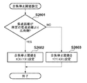
図17のS1301で実行する、本実施形態の合焦停止閾値設定について、図23のフローチャートを用いて説明する。
S2601でカメラ制御部212(合焦停止判定部213)は、レンズユニット30の焦点距離が所定の焦点距離より広角側(小さい値か)かどうかを判断し、広角側である場合はS2602へ、そうでない場合はS2603へ処理を進める。合焦停止判定部213はS2602で合焦停止閾値をXに、S2603では合焦停止閾値をYに設定して処理を終了する。
本実施形態で設定する合焦停止閾値X、Yは、第1の実施形態における合焦停止閾値X、Yと同様に、X<Yという大小関係を有し、Yは2以上、Xを1に設定する点も第1の実施形態で説明した例と同様である。
The focus stop threshold value setting of this embodiment executed in S1301 of FIG. 17 will be described using the flowchart of FIG.
In S2601, the camera control unit 212 (focus stop determination unit 213) determines whether or not the focal length of the
The focus stop threshold values X and Y set in the present embodiment have a magnitude relationship of X <Y, as in the focus stop threshold values X and Y in the first embodiment, where Y is 2 or more and X is 1 This is also the same as the example described in the first embodiment.
本実施形態では、レンズユニット30の焦点距離が所定より広角側である場合に、合焦停止閾値に小さな値Xを設定する。このように制御するのは、一般的に焦点距離が広角側であるほど、焦点深度が大きく、合焦距離の変化に対するフォーカスレンズ位置の変化が小さくなるためである。つまり、一般的に焦点距離が広角側である(小さい)ほど、被写体の距離変化に対してフォーカスレンズを駆動する必要性が小さく、従って追従性に関する問題が小さくなる。従って、フォーカスレンズの駆動回数を減らすに十分な程度、焦点距離が広角側である場合には、合焦停止閾値を1回に設定して、焦点深度内かつ信頼性が所定値より良いデフォーカス量が検出されたらすぐに合焦と判定してフォーカスレンズの駆動を停止する。なお、絞り値とレンズユニット30の焦点距離とから求まるレンズユニット30の焦点深度もしくは被写界深度が所定値以上であれば、合焦停止閾値を1回に設定するようにしてもよい。
In the present embodiment, when the focal length of the
以上説明したように、本実施形態では、焦点距離が所定の焦点距離よりも広角側である場合は、そうでない場合よりも合焦停止閾値を小さく設定することにより、実質的に不要なフォーカスレンズの駆動をより効率的に停止することができる。そのため、合焦度の安定性を向上することができる。
なお、合焦停止閾値に設定するXを1、Yを2以上としたが、第1の実施形態と同様にX<Yの関係であれば他の値を設定することができる。
As described above, in the present embodiment, when the focal length is on the wide-angle side from the predetermined focal length, the focus stop threshold value is set to be smaller than in the case where the focal length is not so that a substantially unnecessary focus lens is obtained. Can be stopped more efficiently. Therefore, the stability of the focus degree can be improved.
Although X is set to 1 and Y is set to 2 or more as the focus stop threshold, other values can be set as long as X <Y as in the first embodiment.
以上、本発明をその例示的な実施形態に基づいて詳述してきたが、本発明はこれら特定の実施形態に限られるものではなく、特許請求の範囲に記載した発明の範囲内で様々な変形、改変を行うことができる。 Although the present invention has been described in detail based on the exemplary embodiments thereof, the present invention is not limited to these specific embodiments, and various modifications can be made within the scope of the invention described in the claims. Modifications can be made.
(他の実施形態)
また、本発明は、以下の処理を実行することによっても実現される。即ち、上述した実施形態の機能を実現するソフトウェア(プログラム)を、ネットワーク又は各種記憶媒体を介してシステム或いは装置に供給し、そのシステム或いは装置のコンピュータ(またはCPUやMPU等)がプログラムを読み出して実行する処理である。
(Other embodiments)
The present invention can also be realized by executing the following processing. That is, software (program) that realizes the functions of the above-described embodiments is supplied to a system or apparatus via a network or various storage media, and a computer (or CPU, MPU, or the like) of the system or apparatus reads the program. It is a process to be executed.
Claims (11)
前記撮影光学系に含まれるフォーカスレンズの駆動を制御する制御手段と、
撮影条件が、予め定めた、前記デフォーカス量の検出精度が低下する条件に合致するかどうかを判定する判定手段と、を有し、
前記制御手段は、
前記検出手段による予め定めた第1の複数回のデフォーカス量検出により、予め定めた量以下のデフォーカス量が、前記第1の複数回以下の予め定めた第2の複数回以上検出された場合に、前記フォーカスレンズの駆動を停止するように前記フォーカスレンズの駆動を制御し、
前記撮影条件が前記条件に合致すると判定された場合には、前記第1の複数回のデフォーカス量検出により、前記予め定めた量以下のデフォーカス量が前記第2の複数回よりも少ない所定回数以上検出された場合に、前記フォーカスレンズの駆動を停止するように前記フォーカスレンズの駆動を制御することを特徴とする撮像装置。 Detection means for detecting a defocus amount of the photographing optical system based on an image signal used for focus detection of a phase difference detection method acquired from an image sensor;
Control means for controlling drive of a focus lens included in the photographing optical system;
Determination means for determining whether or not the photographing condition matches a predetermined condition for reducing the detection accuracy of the defocus amount ;
Wherein,
A defocus amount equal to or less than a predetermined amount has been detected a plurality of predetermined second times equal to or less than the first plurality of times by the first plurality of defocus amount detections performed by the detection unit. Control the drive of the focus lens to stop the drive of the focus lens,
If the previous SL photographing condition is determined to meet the above condition, by the first plurality of defocus amount detection is less than the defocus amount of more than the amount that the predetermined said second plurality of times when it is detected a predetermined number of times or more, the focus lens to that imaging device and controls the driving of the focus lens so as to stop the driving of the.
前記撮影光学系に含まれるフォーカスレンズの駆動を制御する制御手段と、を有し、
前記制御手段は、前記検出手段による予め定めた第1の複数回のデフォーカス量検出により、予め定めた量以下のデフォーカス量が、前記第1の複数回以下の予め定めた第2の複数回以上検出された場合に、前記フォーカスレンズの駆動を停止するように前記フォーカスレンズの駆動を制御し、
前記撮影光学系の焦点距離が可変であり、
前記制御手段は、前記焦点距離が予め定めた値以下である場合には、前記第1の複数回のデフォーカス量検出により、前記予め定めた量以下のデフォーカス量が前記第2の複数回よりも少ない所定回数以上検出された場合に、前記フォーカスレンズの駆動を停止するように前記フォーカスレンズの駆動を制御することを特徴とする撮像装置。 Detection means for detecting a defocus amount of the photographing optical system based on an image signal used for focus detection of a phase difference detection method acquired from an image sensor;
Control means for controlling driving of a focus lens included in the photographing optical system,
The control means detects a predetermined second plurality of defocus amounts less than or equal to a predetermined amount by detecting the defocus amounts for the first predetermined number of times by the detection means. Control the drive of the focus lens to stop the drive of the focus lens when detected more than once,
The focal length of the photographing optical system is variable,
When the focal length is equal to or smaller than a predetermined value, the control means detects a defocus amount equal to or smaller than the predetermined amount by detecting the defocus amount for the first plurality of times. when it is detected smaller predetermined number of times or more than the, the focus lens, wherein the to that imaging device to control the drive of the focus lens so as to stop the driving of the.
前記撮影光学系に含まれるフォーカスレンズの駆動を制御する制御手段と、を有し、Control means for controlling driving of a focus lens included in the photographing optical system,
前記制御手段は、前記検出手段による予め定めた第1の複数回のデフォーカス量検出により、前記信頼性が所定値よりも良く、かつ予め定めた量以下であるデフォーカス量が、前記第1の複数回以下の予め定めた第2の複数回以上検出された場合に、前記フォーカスレンズの駆動を停止するように前記フォーカスレンズの駆動を制御することを特徴とする撮像装置。The control means is configured to detect a defocus amount whose reliability is better than a predetermined value and equal to or less than a predetermined amount by detecting the defocus amount for the first predetermined number of times by the detecting means. The focus lens drive is controlled so as to stop the drive of the focus lens when a predetermined second multiple times or more is detected.
撮影条件が、予め定めた、前記デフォーカス量の検出精度が低下する条件に合致するかどうかを判定する判定工程と、A determination step of determining whether or not the shooting condition matches a predetermined condition for reducing the detection accuracy of the defocus amount;
前記検出工程による予め定めた第1の複数回のデフォーカス量検出により、予め定めた量以下のデフォーカス量が、前記第1の複数回以下の予め定めた第2の複数回以上検出された場合に、前記撮影光学系に含まれるフォーカスレンズの駆動を停止するように前記フォーカスレンズの駆動を制御する制御工程と、を有し、A defocus amount equal to or less than a predetermined amount is detected a plurality of predetermined second times equal to or less than the first plurality of times by detecting the defocus amount for the first predetermined number of times in the detection step. A control step of controlling the drive of the focus lens so as to stop the drive of the focus lens included in the photographing optical system,
前記制御工程では、前記撮影条件が前記条件に合致すると判定された場合には、前記予め定めた量以下のデフォーカス量が前記第2の複数回よりも少ない所定回数以上検出された場合に、前記フォーカスレンズの駆動を停止するように前記フォーカスレンズの駆動を制御することを特徴とする撮像装置の制御方法。In the control step, when it is determined that the shooting condition matches the condition, when a defocus amount equal to or less than the predetermined amount is detected a predetermined number of times less than the second plurality of times, A method for controlling an imaging apparatus, wherein the driving of the focus lens is controlled so as to stop the driving of the focus lens.
前記検出工程による予め定めた第1の複数回のデフォーカス量検出により、予め定めた量以下のデフォーカス量が、前記第1の複数回以下の予め定めた第2の複数回以上検出された場合に、前記撮影光学系に含まれるフォーカスレンズの駆動を停止するように前記フォーカスレンズの駆動を制御する制御工程と、を有し、A defocus amount equal to or less than a predetermined amount is detected a plurality of predetermined second times equal to or less than the first plurality of times by detecting the defocus amount for the first predetermined number of times in the detection step. A control step of controlling the drive of the focus lens so as to stop the drive of the focus lens included in the photographing optical system,
前記撮影光学系の焦点距離が可変であり、The focal length of the photographing optical system is variable,
前記制御工程では、前記焦点距離が予め定めた値以下である場合には、前記第1の複数回のデフォーカス量検出により、前記予め定めた量以下のデフォーカス量が前記第2の複数回よりも少ない所定回数以上検出された場合に、前記フォーカスレンズの駆動を停止するように前記フォーカスレンズの駆動を制御することを特徴とする撮像装置の制御方法。In the control step, when the focal distance is equal to or smaller than a predetermined value, the defocus amount equal to or smaller than the predetermined amount is detected in the second plurality of times by the first defocus amount detection. And controlling the focus lens drive so as to stop the drive of the focus lens when a predetermined number of times less than the predetermined number of times is detected.
前記撮影光学系に含まれるフォーカスレンズの駆動を制御する制御工程と、を有し、A control step of controlling driving of a focus lens included in the photographing optical system,
前記制御工程では、前記検出工程による予め定めた第1の複数回のデフォーカス量検出により、前記信頼性が所定値よりも良く、かつ予め定めた量以下であるデフォーカス量が、前記第1の複数回以下の予め定めた第2の複数回以上検出された場合に、前記フォーカスレンズの駆動を停止するように前記フォーカスレンズの駆動を制御することを特徴とする撮像装置の制御方法。In the control step, a defocus amount whose reliability is better than a predetermined value and equal to or less than a predetermined amount is detected by the first defocus amount detection performed in advance by the detection step. A control method for an imaging apparatus, wherein the driving of the focus lens is controlled so as to stop the driving of the focus lens when it is detected a plurality of predetermined second or more times.
Priority Applications (1)
| Application Number | Priority Date | Filing Date | Title |
|---|---|---|---|
| JP2013093049A JP6139960B2 (en) | 2013-04-25 | 2013-04-25 | Imaging apparatus and control method thereof |
Applications Claiming Priority (1)
| Application Number | Priority Date | Filing Date | Title |
|---|---|---|---|
| JP2013093049A JP6139960B2 (en) | 2013-04-25 | 2013-04-25 | Imaging apparatus and control method thereof |
Publications (3)
| Publication Number | Publication Date |
|---|---|
| JP2014215475A JP2014215475A (en) | 2014-11-17 |
| JP2014215475A5 JP2014215475A5 (en) | 2016-06-09 |
| JP6139960B2 true JP6139960B2 (en) | 2017-05-31 |
Family
ID=51941272
Family Applications (1)
| Application Number | Title | Priority Date | Filing Date |
|---|---|---|---|
| JP2013093049A Active JP6139960B2 (en) | 2013-04-25 | 2013-04-25 | Imaging apparatus and control method thereof |
Country Status (1)
| Country | Link |
|---|---|
| JP (1) | JP6139960B2 (en) |
Families Citing this family (5)
| Publication number | Priority date | Publication date | Assignee | Title |
|---|---|---|---|---|
| JP2016142925A (en) | 2015-02-02 | 2016-08-08 | キヤノン株式会社 | Imaging apparatus, method of controlling the same, program, and storage medium |
| JP6614783B2 (en) * | 2015-03-19 | 2019-12-04 | キヤノン株式会社 | Automatic focusing apparatus and control method thereof |
| JP6808333B2 (en) * | 2015-04-03 | 2021-01-06 | キヤノン株式会社 | Display control device and method, and imaging device |
| US20160295122A1 (en) | 2015-04-03 | 2016-10-06 | Canon Kabushiki Kaisha | Display control apparatus, display control method, and image capturing apparatus |
| JP7066458B2 (en) * | 2018-03-08 | 2022-05-13 | キヤノン株式会社 | Imaging device and its control method, program |
Family Cites Families (6)
| Publication number | Priority date | Publication date | Assignee | Title |
|---|---|---|---|---|
| JPS6160080A (en) * | 1984-08-31 | 1986-03-27 | Asahi Optical Co Ltd | Auto focusing device |
| JP2005274609A (en) * | 2004-03-22 | 2005-10-06 | Olympus Corp | Automatic focusing method and its device |
| JP2006293097A (en) * | 2005-04-12 | 2006-10-26 | Olympus Imaging Corp | Optical device with dust-proof function |
| JP5379739B2 (en) * | 2010-04-30 | 2013-12-25 | キヤノン株式会社 | Lens device |
| JP5966267B2 (en) * | 2011-07-22 | 2016-08-10 | 株式会社ニコン | Focus adjustment device and imaging device |
| JP6346439B2 (en) * | 2013-01-07 | 2018-06-20 | キヤノン株式会社 | Imaging apparatus and control method thereof |
-
2013
- 2013-04-25 JP JP2013093049A patent/JP6139960B2/en active Active
Also Published As
| Publication number | Publication date |
|---|---|
| JP2014215475A (en) | 2014-11-17 |
Similar Documents
| Publication | Publication Date | Title |
|---|---|---|
| US10264173B2 (en) | Image capturing apparatus and control method thereof, and storage medium | |
| US10511781B2 (en) | Image pickup apparatus, control method for image pickup apparatus | |
| US9338344B2 (en) | Focusing apparatus and method for controlling the same, and image pickup apparatus | |
| JP6351234B2 (en) | Automatic focusing device, control method for automatic focusing device, control program for automatic focusing device, and storage medium | |
| JP5322995B2 (en) | Imaging apparatus and control method thereof | |
| JP5543180B2 (en) | Imaging apparatus, control method thereof, and program | |
| JP6139960B2 (en) | Imaging apparatus and control method thereof | |
| US10542202B2 (en) | Control apparatus that performs focusing by imaging-plane phase difference AF, image capturing apparatus, control method, and non-transitory computer-readable storage medium | |
| US9843728B2 (en) | Focus control apparatus, control method therefor, storage medium therefor, and image capturing apparatus | |
| JP7210185B2 (en) | Imaging device and its control method | |
| US20200228719A1 (en) | Focus control apparatus, imaging apparatus, focus control method, and storage medium | |
| JP6087714B2 (en) | Imaging apparatus and control method thereof | |
| JP2008177785A (en) | Imaging apparatus, and its control method | |
| JP6220144B2 (en) | Focus adjustment apparatus and control method thereof | |
| JP6486098B2 (en) | Imaging apparatus and control method thereof | |
| JP6238547B2 (en) | Focus adjustment apparatus and control method thereof | |
| JP2015232604A (en) | Focus adjustment device, focus adjustment method and program, and imaging device | |
| JP2016156950A (en) | Automatic focus adjustment device and control method of the same | |
| JP6305017B2 (en) | Focus control device and control method thereof | |
| CN112422811B (en) | Lens control apparatus, control method, and storage medium | |
| JP7353868B2 (en) | Lens control device and its control method | |
| JP6305016B2 (en) | FOCUS CONTROL DEVICE, FOCUS CONTROL DEVICE CONTROL METHOD, AND IMAGING DEVICE | |
| JP6338353B2 (en) | Automatic focusing device, control method for automatic focusing device, control program for automatic focusing device, and storage medium | |
| JP2012141436A (en) | Focus detector and control method therefor | |
| JP2011013499A (en) | Imaging apparatus |
Legal Events
| Date | Code | Title | Description |
|---|---|---|---|
| A521 | Request for written amendment filed |
Free format text: JAPANESE INTERMEDIATE CODE: A523 Effective date: 20160413 |
|
| A621 | Written request for application examination |
Free format text: JAPANESE INTERMEDIATE CODE: A621 Effective date: 20160413 |
|
| A977 | Report on retrieval |
Free format text: JAPANESE INTERMEDIATE CODE: A971007 Effective date: 20161227 |
|
| A131 | Notification of reasons for refusal |
Free format text: JAPANESE INTERMEDIATE CODE: A131 Effective date: 20170106 |
|
| A521 | Request for written amendment filed |
Free format text: JAPANESE INTERMEDIATE CODE: A523 Effective date: 20170303 |
|
| TRDD | Decision of grant or rejection written | ||
| A01 | Written decision to grant a patent or to grant a registration (utility model) |
Free format text: JAPANESE INTERMEDIATE CODE: A01 Effective date: 20170331 |
|
| A61 | First payment of annual fees (during grant procedure) |
Free format text: JAPANESE INTERMEDIATE CODE: A61 Effective date: 20170428 |
|
| R151 | Written notification of patent or utility model registration |
Ref document number: 6139960 Country of ref document: JP Free format text: JAPANESE INTERMEDIATE CODE: R151 |