EP2383005A1 - Vorfüllspritze - Google Patents
Vorfüllspritze Download PDFInfo
- Publication number
- EP2383005A1 EP2383005A1 EP11001648A EP11001648A EP2383005A1 EP 2383005 A1 EP2383005 A1 EP 2383005A1 EP 11001648 A EP11001648 A EP 11001648A EP 11001648 A EP11001648 A EP 11001648A EP 2383005 A1 EP2383005 A1 EP 2383005A1
- Authority
- EP
- European Patent Office
- Prior art keywords
- piston
- receiving sleeve
- nozzle
- seal
- groove
- Prior art date
- Legal status (The legal status is an assumption and is not a legal conclusion. Google has not performed a legal analysis and makes no representation as to the accuracy of the status listed.)
- Granted
Links
- 238000002347 injection Methods 0.000 title 1
- 239000007924 injection Substances 0.000 title 1
- 239000012530 fluid Substances 0.000 claims description 19
- 230000008878 coupling Effects 0.000 claims description 5
- 238000010168 coupling process Methods 0.000 claims description 5
- 238000005859 coupling reaction Methods 0.000 claims description 5
- 230000037431 insertion Effects 0.000 claims 1
- 238000003780 insertion Methods 0.000 claims 1
- 238000007789 sealing Methods 0.000 description 3
- 230000006978 adaptation Effects 0.000 description 2
- 238000007599 discharging Methods 0.000 description 2
- 239000002537 cosmetic Substances 0.000 description 1
- 239000000463 material Substances 0.000 description 1
- 238000004806 packaging method and process Methods 0.000 description 1
- 239000007787 solid Substances 0.000 description 1
Images


Classifications
-
- A—HUMAN NECESSITIES
- A61—MEDICAL OR VETERINARY SCIENCE; HYGIENE
- A61M—DEVICES FOR INTRODUCING MEDIA INTO, OR ONTO, THE BODY; DEVICES FOR TRANSDUCING BODY MEDIA OR FOR TAKING MEDIA FROM THE BODY; DEVICES FOR PRODUCING OR ENDING SLEEP OR STUPOR
- A61M5/00—Devices for bringing media into the body in a subcutaneous, intra-vascular or intramuscular way; Accessories therefor, e.g. filling or cleaning devices, arm-rests
- A61M5/002—Packages specially adapted therefor, e.g. for syringes or needles, kits for diabetics
-
- A—HUMAN NECESSITIES
- A61—MEDICAL OR VETERINARY SCIENCE; HYGIENE
- A61M—DEVICES FOR INTRODUCING MEDIA INTO, OR ONTO, THE BODY; DEVICES FOR TRANSDUCING BODY MEDIA OR FOR TAKING MEDIA FROM THE BODY; DEVICES FOR PRODUCING OR ENDING SLEEP OR STUPOR
- A61M5/00—Devices for bringing media into the body in a subcutaneous, intra-vascular or intramuscular way; Accessories therefor, e.g. filling or cleaning devices, arm-rests
- A61M5/178—Syringes
- A61M5/31—Details
- A61M5/315—Pistons; Piston-rods; Guiding, blocking or restricting the movement of the rod or piston; Appliances on the rod for facilitating dosing ; Dosing mechanisms
- A61M5/31511—Piston or piston-rod constructions, e.g. connection of piston with piston-rod
-
- A—HUMAN NECESSITIES
- A61—MEDICAL OR VETERINARY SCIENCE; HYGIENE
- A61M—DEVICES FOR INTRODUCING MEDIA INTO, OR ONTO, THE BODY; DEVICES FOR TRANSDUCING BODY MEDIA OR FOR TAKING MEDIA FROM THE BODY; DEVICES FOR PRODUCING OR ENDING SLEEP OR STUPOR
- A61M5/00—Devices for bringing media into the body in a subcutaneous, intra-vascular or intramuscular way; Accessories therefor, e.g. filling or cleaning devices, arm-rests
- A61M5/178—Syringes
- A61M5/31—Details
- A61M2005/3112—Incorporating self-aspirating means, e.g. to provide flashback
-
- A—HUMAN NECESSITIES
- A61—MEDICAL OR VETERINARY SCIENCE; HYGIENE
- A61M—DEVICES FOR INTRODUCING MEDIA INTO, OR ONTO, THE BODY; DEVICES FOR TRANSDUCING BODY MEDIA OR FOR TAKING MEDIA FROM THE BODY; DEVICES FOR PRODUCING OR ENDING SLEEP OR STUPOR
- A61M5/00—Devices for bringing media into the body in a subcutaneous, intra-vascular or intramuscular way; Accessories therefor, e.g. filling or cleaning devices, arm-rests
- A61M5/178—Syringes
- A61M5/28—Syringe ampoules or carpules, i.e. ampoules or carpules provided with a needle
- A61M5/281—Syringe ampoules or carpules, i.e. ampoules or carpules provided with a needle using emptying means to expel or eject media, e.g. pistons, deformation of the ampoule, or telescoping of the ampoule
- A61M5/282—Syringe ampoules or carpules, i.e. ampoules or carpules provided with a needle using emptying means to expel or eject media, e.g. pistons, deformation of the ampoule, or telescoping of the ampoule by compression of deformable ampoule or carpule wall
-
- A—HUMAN NECESSITIES
- A61—MEDICAL OR VETERINARY SCIENCE; HYGIENE
- A61M—DEVICES FOR INTRODUCING MEDIA INTO, OR ONTO, THE BODY; DEVICES FOR TRANSDUCING BODY MEDIA OR FOR TAKING MEDIA FROM THE BODY; DEVICES FOR PRODUCING OR ENDING SLEEP OR STUPOR
- A61M5/00—Devices for bringing media into the body in a subcutaneous, intra-vascular or intramuscular way; Accessories therefor, e.g. filling or cleaning devices, arm-rests
- A61M5/178—Syringes
- A61M5/31—Details
- A61M5/315—Pistons; Piston-rods; Guiding, blocking or restricting the movement of the rod or piston; Appliances on the rod for facilitating dosing ; Dosing mechanisms
- A61M5/31511—Piston or piston-rod constructions, e.g. connection of piston with piston-rod
- A61M5/31513—Piston constructions to improve sealing or sliding
-
- A—HUMAN NECESSITIES
- A61—MEDICAL OR VETERINARY SCIENCE; HYGIENE
- A61M—DEVICES FOR INTRODUCING MEDIA INTO, OR ONTO, THE BODY; DEVICES FOR TRANSDUCING BODY MEDIA OR FOR TAKING MEDIA FROM THE BODY; DEVICES FOR PRODUCING OR ENDING SLEEP OR STUPOR
- A61M5/00—Devices for bringing media into the body in a subcutaneous, intra-vascular or intramuscular way; Accessories therefor, e.g. filling or cleaning devices, arm-rests
- A61M5/178—Syringes
- A61M5/31—Details
- A61M5/315—Pistons; Piston-rods; Guiding, blocking or restricting the movement of the rod or piston; Appliances on the rod for facilitating dosing ; Dosing mechanisms
- A61M5/31533—Dosing mechanisms, i.e. setting a dose
- A61M5/31545—Setting modes for dosing
- A61M5/31548—Mechanically operated dose setting member
- A61M5/3156—Mechanically operated dose setting member using volume steps only adjustable in discrete intervals, i.e. individually distinct intervals
Definitions
- the present invention relates to a Vor whll moussee according to the features of the preamble of claim 1 and the independent claims for use of this.
- the object of the present invention is to eliminate disadvantages of the prior art and to improve the above-mentioned prefill syringes and to obtain as compact a design as possible,
- a prefill syringe is prefilled with a fluid supplied to the user. While the fluid is primarily intended to meet medical concerns, it is also possible to satisfy cosmetic concerns with the fluid.
- a transport state is preferably a state in which usually the prefill syringe according to the invention is packaged by the manufacturer and sent to the user.
- a working condition is preferably a condition in which the prefill syringe is operated by a user.
- the Vor colllspritze consists of a receiving sleeve with a nozzle and a piston.
- the piston should preferably be designed in such a way that it is inserted in a transport state via the nozzle-side end of the receiving sleeve.
- parts of the piston may also protrude through the nozzle into the interior of the receiving sleeve. Likewise, the same parts may serve to close the nozzle of the receiving sleeve during Transpost réelles.
- the piston should be designed in such a way that it is at least partially inserted into the receiving sleeve in a working state.
- Working state means the discharge of the fluid from the Vorchirllspritze. This can be done all at once or in several stages.
- the advantage here is that the piston is first pushed to save space on the nozzle-side end during the TranspostSullivan and the user for discharging the fluid in the working state for discharging the fluid at the nozzle-side end facing away from the area in the receiving sleeve.
- the piston can in this case also close the nozzle during the TranspostSullivans and open during the working state. It is also possible for the piston to be alternately pushed or pushed in alternately either at the nozzle-side end or at the end remote from the nozzle-side end, either via the receiving sleeve or into the receiving sleeve.
- the circumference of the piston should be variable in a preferred embodiment.
- the piston should have a larger circumference than the receiving sleeve and during the Working state, the piston should have a smaller circumference than the inner circumference of the receiving sleeve and be suitable to move completely or partially into the receiving sleeve. This allows the advantage of space savings.
- a preferred embodiment has a seal in the interior of the receiving sleeve.
- this seal advantageously prevents the fluid from running out on the side facing away from the nozzle-side end.
- the seal cooperates with the piston during the working state.
- it has a coupling which is adapted to receive the piston in the working state. This in turn contributes to the advantage of space savings, since during the transport state, the piston is no longer necessary for closing the nozzle-side end facing away from the end.
- the receiving sleeve has a groove on the inside.
- This groove can be stepped, straight or a concentric arc. It has the advantage that the user is pressed, for example, when metered application in the step-shaped design always only to the end of a straight-down portion of fluid from the nozzle and the impingement of the fluid is stopped when the piston hits a vertically extending point and the user first has to rotate the piston in the direction of the vertically extending groove, the rotation takes place until the user again encounters a straight downwardly extending groove and presses the next dose of fluid from the receiving sleeve.
- the end facing away from the nozzle-side end and bottom is to be equated with the nozzle-side end.
- the piston or a portion of the seal has in a preferred embodiment, a cam cam which cooperates with the groove.
- This curve cam serves to allow the user to guide the piston only along the groove as intended. The advantage here is that even untrained personnel can deliver metered amounts of fluid.
- the receiving sleeve on a recessed grip has the advantage that the user can hold the receiving sleeve during the working state. Since the piston is pushed over the receiving sleeve, the ring formed in the prior art for this purpose is absent at the end facing away from the nozzle end. The advantage here is that the user can keep safe by the recessed grip against the pressure of the piston in the working state.
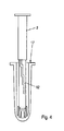
- FIG. 1 a prefill syringe R according to the invention is shown.
- This is a sectional side view.
- a piston 2 is arranged.
- This piston 2 protrudes with a part 3 through a nozzle 4 of the receiving sleeve 1 in the filling region 5 of the receiving sleeve.
- a medium 6 is introduced in advance.
- a seal 7 can be seen.
- This seal 7 has at least one sealing lip 8 on the side facing the fluid 6.
- a coupling 9 is shown in the seal 7.
- FIG. 2 now shows how the piston 2 is placed on top of the receiving sleeve 1 from above.
- the piston 2 comprises the circumference of the receiving sleeve 1.
- the part 3 is now introduced into the coupling 9 of the seal 7. If the user now presses on a pressure point 10 of the receiving sleeve 2, the part 3 will actuate the seal 7 and moved in the direction of arrow P. In this case, it is the medium 6, which is located in the receiving space 5 push through the nozzle 4.
- FIG. 2 a curve cam 11 shown.
- FIG. 3 shows a further embodiment of an inventive receiving sleeve 12.
- a recessed grip 13 is formed in this receiving sleeve 12.
- a stepped groove 14 or a straight groove 15 is shown on the inside of the receiving sleeve 12. Even if the stepped groove 14 in FIG. 3 is not shown extending to the bottom 16 of the receiving sleeve 12, this is assumed.
- Cam cam 11 shown serves the purpose that the user can make the actuation in the direction of arrow P along a straight groove 15 or a stepped groove 14.
- the cam cam 11 engages in the corresponding groove 14 or 15 and the user presses on the receiving surface 10 in the direction of arrow P with the seal 7 is then guided along the corresponding groove 14 or 15 down.
- the step-shaped groove 14 would have the advantage that a metered discharge of the fluid 6 would be possible.
- the user could push all the fluid 6 out of the receiving sleeve 12 in one movement.
- receiving sleeve 12 can also be operated with the piston 2, as with the receiving sleeve. 1
- FIG. 4 shows another embodiment. There is simplified the receiving sleeve 12 and the piston 2 shown in working condition. In addition, it can be seen how an adaptation 17 is mounted almost over the entire region of the receiving sleeve 12.
- This embodiment is intended to make clear that the device according to the invention should also be able to be used with conventional adaptions, as used, for example, in vaginal application.
- FIG. 5 shows a further embodiment of a Vor colllspritze invention.
- a piston 18 and a closure 19 are shown.
- the closure 19 closes the nozzle 20 of the receiving sleeve 21, which in FIG. 5 shown only partially cut.
- the receiving sleeve 21 forms a ring 22 at its upper end.
- the receiving sleeve 21 is located inside the receiving sleeve 21 again a seal 23 with a coupling 24.
- the seal 23 also has at least one unspecified sealing lip, which does not allow the pre-filled fluid escape upwards.
- the seal 23 has a rim 25 and a circular recess 26.
- the inside of the receiving sleeve 21 forms with the outer surface of the ring 24 a receiving space 27th
- FIG. 7 It is now shown how the piston 18 has been pulled by the receiving sleeve 20. Subsequently, the lamellar outer skin of the piston 18 has been changed in such a way that the outer periphery of the piston 18 now fits either into the receiving space 27 or even into the recess 26 of the seal 23.
- the lock 19 is now used to push the piston 18 in the direction of arrow X and thereby push the seal 23 toward the nozzle 20, a fluid which is located in the receiving sleeve 21, pressed by the seal 23 from the nozzle 20.
- FIG. 8 is again shown how the piston 18 has been pushed over the receiving sleeve 21 with a larger circumference.
- FIG. 9 shows how the piston 18 is mounted with reduced circumference within the receiving sleeve 21 and along the inner skin of the receiving sleeve 21 can be moved.
Landscapes
- Health & Medical Sciences (AREA)
- Heart & Thoracic Surgery (AREA)
- Life Sciences & Earth Sciences (AREA)
- Engineering & Computer Science (AREA)
- Anesthesiology (AREA)
- Biomedical Technology (AREA)
- Veterinary Medicine (AREA)
- Hematology (AREA)
- Vascular Medicine (AREA)
- Animal Behavior & Ethology (AREA)
- General Health & Medical Sciences (AREA)
- Public Health (AREA)
- Diabetes (AREA)
- Infusion, Injection, And Reservoir Apparatuses (AREA)
- Dental Tools And Instruments Or Auxiliary Dental Instruments (AREA)
Abstract
Description
- Die vorliegende Erfindung betrifft eine Vorfüllspritze nach den Merkmalen des Oberbegriffs des Anspruchs 1 sowie der nebengeordneten Verwendungsansprüche zur Nutzung dieser.
- Aus dem Stand der Technik sind vielfältige so genannte Vorfüllspritzen bekannt. Nachteilig hierbei ist allerdings, dass aufgrund des im Spritzenkörper befindlichen Mediums der zur Spritze dazugehörige Kolben nicht im Spritzenkörper gelagert werden kann, sondern in der Regel in der Weise transportiert wird, dass der Kolben aus dem Spritzenkörper herausgezogen ist und der Nutzer dann den Kolben durch Niederdrücken betätigt und das Medium aus dem Spritzenkörper drückt. Durch den ausgezogenen Kolben bedarf es hier aber eines beträchtlichen Materialaufwandes für die Verpackung und Platzaufwandes für den Transport.
- Aufgabe der vorliegenden Erfindung ist es, Nachteile des Standes der Technik abzustellen und oben genannte vorfüllspritzen zu verbessern und dabei möglichst eine kompakte Ausgestaltung zu erhalten,
- Zur Lösung der Aufgabe führen die Merkmale des kennzeichnenden Teils des Anspruchs 1, sowie der nebengeordneten Verwendungsansprüche.
- Eine Vorfüllspritze wird vorgefüllt mit einem Fluid an den Nutzer geliefert. Das Fluid soll zwar in erster Linie medizinischen Belangen genügen, doch ist es ebenfalls möglich kosmetischen Belangen mit dem Fluid Genüge zu tun.
- Ein Transportzustand ist vorzugsweise ein Zustand in dem üblicherweise die erfindungsgemäße Vorfüllspritze vom Hersteller verpackt und an den Nutzer versandt wird. Ein Arbeitszustand ist vorzugsweise ein Zustand in dem die Vorfüllspritze durch einen Nutzer betätigt wird.
- Die Vorfüllspritze besteht aus einer Aufnahmehülse mit einer Düse und einem Kolben. Der Kolben soll bevorzugt in der Weise ausgebildet sein, dass er in einem Transportzustand über das düsen-seitige Ende der Aufnahmehülse gesteckt ist. Vorteilhaft hierbei ist, dass durch diese Steckverbindung ein Platzersparnis erreicht wird, da herkömmliche Vorfüllspritzen mit einem ausgezogenen Kolben an den Nutzer versandt werden muss, um das Fluid mit senden zu können.
- In einem bevorzugten Ausführungsbeispiel können Teile des Kolbens durch die Düse auch in das Innere der Aufnahmehülse ragen. Ebenso können die gleichen Teile dazu dienen die Düse der Aufnahmehülse während des Transpostzustands zu verschließen.
- Außerdem soll der Kolben in der Weise ausgebildet sein, dass er in einem Arbeitszustand zumindest teilweise in die Aufnahmehülse einschiebbar ist. Arbeitszustand bedeutet hierbei das Ausbringen des Fluids aus der Vorfüllspritze. Dies kann auf einmal oder in mehrere Stufen geschehen. Vorteilhaft hierbei ist, dass der Kolben während des Transpostzustand zunächst platzsparend am Düsen-seitigen Ende aufgeschoben ist und der Nutzer zum Ausbringen des Fluids den Kolben im Arbeitszustand zum Ausbringen des Fluids am dem Düsen-seitigen Ende abgewandten Bereich in die Aufnahmehülse schieben kann.
- Der Kolben kann hierbei auch die Düse während des Transpostzustands verschließen und während des Arbeitszustands öffnen. Es ist auch möglich, dass der Kolben mehrmals abwechselnd entweder am Düsen-seitigen Ende oder dem dem Düsen-seitigen Ende abgewandten Ende entweder über die Aufnahmehülse oder in die Aufnahmehülse auf- oder eingeschoben werden kann.
- Der Umfang des Kolbens soll in einem bevorzugten Ausführungsbeispiel veränderbar sein. Während des Transportzustands soll der Kolben einen größeren Umfang aufweisen als die Aufnahmehülse und während des Arbeitszustands soll der Kolben einen geringeren Umfang als der Innenumfang der Aufnahmehülse aufweisen und geeignet sein ganz oder teilweise in die Aufnahmehülse zu verfahren. Dies ermöglicht den Vorteil der Platzersparnis.
- Ein bevorzugtes Ausführungsbeispiel weist eine Dichtung im Inneren der Aufnahmehülse auf. Diese Dichtung verhindert zum einen vorteilhaft, dass das Fluid auf der dem Düsen-seitigen Ende abgewandtem Seite ausläuft. Außerdem wirkt die Dichtung mit dem Kolben während des Arbeitszustandes zusammen. Dazu weist sie eine Kupplung auf, welche dazu geeignet ist, den Kolben im Arbeitszustand aufzunehmen. Dies trägt wiederum zum Vorteil der Platzersparnis bei, da während des Transportzustands der Kolben zum Verschließen des dem Düsen-seitigen Ende abgewandten Endes nicht mehr notwendig ist.
- In einem bevorzugten Ausführungsbeispiel weist die Aufnahmehülse innenseitig eine Nut aufweist. Diese Nut kann stufenförmig, gerade oder einem konzentrischen Bogen verlaufen. Sie weist den Vorteil auf, dass der Nutzer beispielsweise bei dosierter Anwendung in der stufenförmigen Ausführung immer nur bis zum Ende eines gerade nach unten verlaufenden Teils Fluid aus der Düse gedrückt wird und bei Auftreffen des Kolbens auf eine senkrecht verlaufende Stelle das Ausbringen von Fluid gestoppt wird und der Nutzer zunächst den Kolben in Richtung der senkrecht verlaufenden Nut drehen muss, Das Drehen erfolgt solange bis der Nutzer wieder auf eine gerade nach unten verlaufende Nut stößt und die nächste Dosis des Fluids aus der Aufnahmehülse drückt. Oben bedeutet in diesem Zusammenhang, das dem Düsen-seitigen Ende abgewandte Ende und unten ist mit dem Düsen-seitigen Ende gleichzusetzen.
- Der Kolben oder ein Bereich der Dichtung weist in einem bevorzugten Ausführungsbeispiel eine Kurvennocke auf, welche mit der Nut zusammenwirkt. Diese Kurvennocke dient dazu, dass der Nutzer den Kolben nur entlang der Nut bestimmungsgemäß führen kann. Vorteilhaft hierbei ist, dass auch ungeschultes Personal dosierte Fluidmengen abgeben kann.
- In einem anderen bevorzugten Ausführungsbeispiel weist die Aufnahmehülse eine Griffmulde auf. Diese Griffmulde hat den Vorteil dass der Nutzer die Aufnahmehülse während des Arbeitszustandes halten kann. Da der Kolben über die Aufnahmehülse geschoben wird, fehlt der im Stand der Technik hierfür ausgebildete Ring am dem Düsen-seitigen Ende abgewandten Ende. Vorteilhaft hierbei ist, dass der Nutzer durch die Griffmulde gegen den Druck des Kolbens im Arbeitszustand sicher halten kann.
- Weitere Vorteile, Merkmale und Einzelheiten der Erfindung ergeben sich aus der nachfolgenden Beschreibung bevorzugter Ausführungsbeispiele sowie anhand der Zeichnungen; diese zeigen in
-
Figur 1 ein erfindungsgemäßes Ausführungsbeispiel einer Vorfüllspritze im Transportzustand. -
Figur 2 das erfindungsgemäße Ausführungsbeispiel nachFigur 1 im Arbeitszustand; -
Figur 3 ein Ausführungsbeispiel einer erfindungsgemäßen Aufnahmehülse; -
Figur 4 ein weiteres Ausführungsbeispiel einer erfindungsgemäßen Vorfüllspritze; -
Figur 5 ein Ausführungsbeispiel einer anderen erfindungsgemäße Vorfüllspritze im Transportzustand; -
Figur 6 eine geschnittene Seitenansicht einer Aufnahmehülse ausFigur 5 ; -
Figur 7 eine erfindungsgemäße Vorfüllspritze im Arbeitszustand; -
Figur 8 eine geschnittene Queransicht vonFigur 5 ; -
Figur 9 eine geschnittene Queransicht vonFigur 7 . - In
Figur 1 ist eine erfindungsgemäße Vorfüllspritze R gezeigt. Dabei handelt es sich um eine geschnittene Seitenansicht. Dort ist gut zu erkennen, wie um die Aufnahmehülse 1 ein Kolben 2 angeordnet ist. Dieser Kolben 2 ragt mit einem Teil 3 durch eine Düse 4 der Aufnahmehülse 1 in den Füllbereich 5 der Aufnahmehülse. In diesem Füllbereich 5 ist vorab ein Medium 6 eingebracht. Ausserdem ist eine Dichtung 7 zu erkennen. Diese Dichtung 7 weist auf der zum Fluid 6 weisenden Seite zumindest eine Dichtlippe 8 auf. Ausserdem ist in der Dichtung 7 eine Kupplung 9 gezeigt. -
Figur 2 zeigt nun, wie der Kolben 2 von oben auf die Aufnahmehülse 1 gesetzt wird. Dabei umfasst der Kolben 2 den Umfang der Aufnahmehülse 1. Das Teil 3 ist nun in die Kupplung 9 der Dichtung 7 eingebracht. Wenn der Nutzer nun auf einen Druckpunkt 10 der Aufnahmehülse 2 drückt, wird das Teil 3 die Dichtung 7 betätigen und in Pfeilrichtung P verfahren. Dabei wird es das Medium 6, welches sich im Aufnahmeraum 5 befindet durch die Düse 4 hinausdrücken. - Ausserdem ist in
Figur 2 eine Kurvennocke 11 gezeigt. In diesem Zusammenhang wird auf dieFigur 3 hingewiesen. DieFigur 3 zeigt ein weiteres Ausführungsbeispiel einer erfindungsgemässen Aufnahmehülse 12. In dieser Aufnahmehülse 12 ist eine Griffmulde 13 eingeformt. Daneben ist auf der Innenseite der Aufnahmehülse 12 eine stufenförmig verlaufende Nut 14 oder eine gerade laufende Nut 15 gezeigt. Auch wenn die stufenförmige Nut 14 inFigur 3 nicht bis zum Boden 16 der Aufnahmehülse 12 verlaufend gezeigt ist, wird dies unterstellt. - Die in
Figur 2 gezeigte Kurvennocke 11 dient dazu, dass der Nutzer entlang einer geraden Nut 15 oder einer stufenförmigen Nut 14 die Betätigung in Pfeilrichtung P vornehmen kann. - Dabei greift die Kurvennocke 11 in die entsprechende Nut 14 oder 15 und der Nutzer drückt auf die Aufnahmefläche 10 in Pfeilrichtung P wobei die Dichtung 7 dann entlang der entsprechenden Nut 14 oder 15 nach unten geführt wird.
- Die stufenförmige Nut 14 würde hier den Vorteil aufweisen, dass ein dosiertes Ausbringen des Fluids 6 möglich wäre, Bei Eingriff der Kurvennocke 11 in die geradlinig verlaufende Nut 15 könnte der Nutzer das gesamte Fluid 6 aus der Aufnahmehülse 12 in einer Bewegung hinausdrücken. Die in
Figur 3 gezeigte Aufnahmehülse 12 kann ebenso mit dem Kolben 2 betätigt werden, wie mit der Aufnahmehülse 1. -
Figur 4 zeigt ein anderes Ausführungsbeispiel. Dort ist vereinfacht die Aufnahmehülse 12 und der Kolben 2 in Arbeitszustand gezeigt. Ausserdem ist zu erkennen, wie fast über den gesamten Bereich der Aufnahmehülse 12 eine Adaption 17 aufgezogen ist. Dieses Ausführungsbeispiel soll verdeutlichen, dass die erfindungsgemässe Vorrichtung auch mit herkömmlichen Adaptionen, wie sie beispielsweise bei der Vaginalanwendung zum Einsatz kommen, genutzt werden können soll. -
Figur 5 zeigt ein weiteres Ausführungsbeispiel einer erfindungsgemäßen Vorfüllspritze. Dort sind ein Kolben 18 sowie ein Verschluss 19 gezeigt. Der Verschluss 19 verschließt die Düse 20 der Aufnahmehülse 21, welche inFigur 5 nur teilweise geschnitten gezeigt ist. Ausserdem formt die Aufnahmehülse 21 an ihrem oberen Ende einen Ring 22 aus. - Wie in
Figur 6 gut zu erkennen ist, befindet sich im Inneren der Aufnahmehülse 21 wieder eine Dichtung 23 mit einer Kupplung 24. Die Dichtung 23 verfügt außerdem über zumindest eine nicht näher beschriebene Dichtungslippe, welche das vorab eingefüllte Fluid nicht nach oben entweichen lässt. Ausserdem verfügt die Dichtung 23 über einen Kranz 25 und eine kreisförmige Ausnehmung 26. Die Innenseite der Aufnahmehülse 21 bildet mit der Außenfläche des Rings 24 einen Aufnahmeraum 27. - In
Figur 7 ist nun gezeigt, wie der Kolben 18 von der Aufnahmehülse 20 gezogen wurde. Anschließend wurde die lamellenförmige Außenhaut des Kolbens 18 in der Weise verändert, dass der Außenumfang des Kolbens 18 nun entweder in den Aufnahmeraum 27 oder gar in den Ausnehmung 26 der Dichtung 23 passt. - Die Verriegelung 19 dient nun dazu, den Kolben 18 in Pfeilrichtung X zu drücken und dabei die Dichtung 23 hin zur Düse 20 zu schieben, Dabei wird ein Fluid, welches sich in der Aufnahmehülse 21 befindet, durch die Dichtung 23 aus der Düse 20 gedrückt.
- In
Figur 8 ist nochmals gezeigt, wie der Kolben 18 mit einem größeren Umfang über die Aufnahmehülse 21 geschoben wurde. -
Figur 9 zeigt wie der Kolben 18 mit verringertem Umfang innerhalb der Aufnahmehülse 21 gelagert ist und entlang der Innenhaut der Aufnahmehülse 21 verfahren werden kann. -
1 Aufnahmehülse 34 67 2 Kolben 35 68 3 Teil 36 69 4 Düse 37 70 5 Füllbereich 38 71 6 Fluid 39 72 7 Dichtung 40 73 8 Dichtlippe 41 74 9 Kupplung 42 75 10 Druckpunkt 43 76 11 Kurvennocke 44 77 12 Aufnahmehülse 45 78 13 Griffmulde 46 79 14 Nut 47 15 Nut 48 16 Boden 49 17 Adaption 50 18 Kolben 51 19 Verschluss 52 20 53 21 54 22 55 23 56 24 57 25 58 26 59 27 60 28 61 29 62 30 63 31 64 32 65 33 66
Claims (11)
- Vorfüllspritze mit
einer Aufnahmehülse (1, 12, 21) mit einer an einem Düsen-seitigen Ende der Aufnahmehülse (1, 12, 21) angeordneten Düse (4, 20) und
einem Kolben (2, 18),
dadurch gekennzeichnet, dass
der Kolben (2, 18) ausgebildet ist, so dass er für einen Transportzustand an dem Düsen-seitigen Ende der Aufnahmehülse (1, 12, 21) mit der Aufnahmehülse (1, 12, 21) verbindbar ist. - Vorfüllspritze nach Anspruch 1, dadurch gekennzeichnet, dass der Kolben (2, 18) ausgebildet ist, so dass er für einen Arbeitszustand zumindest teilweise in die Aufnahmehülse (1, 12, 21) einschiebbar ist,
- Vorfüllspritze nach einem der vorherigen Ansprüche, dadurch gekennzeichnet, dass der Umfang des Kolbens (2, 18) veränderbar ist.
- Vorfüllspritze nach einem der vorherigen Ansprüche, dadurch gekennzeichnet, dass in der Aufnahmehülse (1, 12, 21) eine mit dem Kolben (2, 18) für den Arbeitszustand verbindbare Dichtung (7, 23) angeordnet ist.
- Vorfüllspritze nach Anspruch 4, dadurch gekennzeichnet, dass die Dichtung (7, 23) eine Kupplung (9, 24) zur Verbindung der Dichtung (7, 23) mit dem Kolben (2, 18) aufweist,
- Vorfüllspritze nach einem der vorherigen Ansprüche, dadurch gekennzeichnet, dass die Aufnahmehülse (1, 12, 21) innenseitig eine Nut (14, 15) aufweist.
- Vorfüllspritze nach Anspruch 6, dadurch gekennzeichnet, dass die Nut (14, 15) stufenförmig abgesetzt oder gerade verläuft.
- Vorfüllspritze nach Anspruch 6 oder 7, dadurch gekennzeichnet, dass der Kolben (2, 18) eine Kurvennocke aufweist, die ausgebildet ist, um mit der Nut (14, 15) zusammenzuwirken.
- Vorfüllspritze nach einem der vorherigen Ansprüche, dadurch gekennzeichnet, dass die Aufnahmehülse (1, 12, 21) eine Griffmulde (13) aufweist.
- Verwendung einer Vorfüllspritze nach einem der Ansprüche 1 bis 9, gekennzeichnet durch folgende Schritte:- Abziehen des Kolbens (2, 18) von der Aussenseite der Aufnahmehülse (1, 12, 21),- Einschieben zumindest eines Teil des Kolbens (2, 18) in die Aufnahmehülse (1,12, 21),- Ausbringen eines in der Aufnahmehülse (1, 12, 21) befindlichen Fluids (6) durch Betätigen des Kolbens (2, 18).
- Verwendung nach Anspruch 10, dadurch gekennzeichnet, dass- vor dem Schritt des Einschiebens und nach dem Schritt des Abziehens ein Umfang des Kolbens (2, 18) verändert wird.
Applications Claiming Priority (1)
| Application Number | Priority Date | Filing Date | Title |
|---|---|---|---|
| DE102010010967A DE102010010967A1 (de) | 2010-03-10 | 2010-03-10 | Vorfüllspritze |
Publications (2)
| Publication Number | Publication Date |
|---|---|
| EP2383005A1 true EP2383005A1 (de) | 2011-11-02 |
| EP2383005B1 EP2383005B1 (de) | 2016-02-24 |
Family
ID=44507819
Family Applications (1)
| Application Number | Title | Priority Date | Filing Date |
|---|---|---|---|
| EP11001648.2A Active EP2383005B1 (de) | 2010-03-10 | 2011-03-01 | Vorfüllspritze |
Country Status (4)
| Country | Link |
|---|---|
| US (1) | US9592334B2 (de) |
| EP (1) | EP2383005B1 (de) |
| DE (1) | DE102010010967A1 (de) |
| ES (1) | ES2571236T3 (de) |
Cited By (1)
| Publication number | Priority date | Publication date | Assignee | Title |
|---|---|---|---|---|
| CN110430906A (zh) * | 2017-03-13 | 2019-11-08 | 赛诺菲-安万特德国有限公司 | 药物输送装置 |
Families Citing this family (1)
| Publication number | Priority date | Publication date | Assignee | Title |
|---|---|---|---|---|
| EP3798138A1 (de) * | 2019-09-30 | 2021-03-31 | SCHOTT Schweiz AG | Vorrichtung und verfahren zum verschliessen von unten |
Citations (4)
| Publication number | Priority date | Publication date | Assignee | Title |
|---|---|---|---|---|
| US2607341A (en) * | 1948-12-24 | 1952-08-19 | Frederick M Turnbull | Hypodermic syringe assembly |
| US2725057A (en) * | 1951-11-23 | 1955-11-29 | Compule Corp | Aspirating hypodermic syringe structures of the piston type featuring means facilitating blood showings |
| US3107785A (en) * | 1960-10-04 | 1963-10-22 | Brunswick Corp | Syringe-container structure |
| FR2356432A1 (fr) * | 1976-07-01 | 1978-01-27 | Dorr Paul | Seringue a usage unique |
Family Cites Families (11)
| Publication number | Priority date | Publication date | Assignee | Title |
|---|---|---|---|---|
| US2728341A (en) * | 1951-11-05 | 1955-12-27 | Zbislaw M Roehr | Hypodermic syringe |
| US2941530A (en) * | 1958-11-14 | 1960-06-21 | Ernest S V Laub | Compressible plunger for hypodermic syringe |
| SE305513B (de) * | 1967-11-22 | 1968-10-28 | L Johansson | |
| US3890956A (en) * | 1974-06-27 | 1975-06-24 | Deseret Pharma | Blood-gas sampler |
| US4184953A (en) | 1977-03-22 | 1980-01-22 | The British Petroleum Company Limited | Physical process |
| US5067947A (en) * | 1989-07-18 | 1991-11-26 | Tri/West Systems, Inc. | Syringe plunger rod mount |
| US7083596B2 (en) * | 2001-06-20 | 2006-08-01 | V. C. Saied | Anesthetizer with automatic needle decommissioning mechanism |
| US7794410B2 (en) * | 2003-12-16 | 2010-09-14 | Idexx Laboratories, Inc. | Tissue sampling device and method |
| CA2512948C (en) * | 2004-07-28 | 2013-10-01 | Ethicon Endo-Surgery, Inc. | Surgical stapling instrument having an electroactive polymer actuated medical substance dispenser |
| US20080132852A1 (en) * | 2004-07-28 | 2008-06-05 | Kleyhan Gennady I | Dosage device |
| US20070148326A1 (en) * | 2005-12-28 | 2007-06-28 | Hastings Mitchell R | Syringe |
-
2010
- 2010-03-10 DE DE102010010967A patent/DE102010010967A1/de not_active Withdrawn
-
2011
- 2011-03-01 ES ES11001648T patent/ES2571236T3/es active Active
- 2011-03-01 EP EP11001648.2A patent/EP2383005B1/de active Active
- 2011-03-08 US US13/042,796 patent/US9592334B2/en not_active Expired - Fee Related
Patent Citations (4)
| Publication number | Priority date | Publication date | Assignee | Title |
|---|---|---|---|---|
| US2607341A (en) * | 1948-12-24 | 1952-08-19 | Frederick M Turnbull | Hypodermic syringe assembly |
| US2725057A (en) * | 1951-11-23 | 1955-11-29 | Compule Corp | Aspirating hypodermic syringe structures of the piston type featuring means facilitating blood showings |
| US3107785A (en) * | 1960-10-04 | 1963-10-22 | Brunswick Corp | Syringe-container structure |
| FR2356432A1 (fr) * | 1976-07-01 | 1978-01-27 | Dorr Paul | Seringue a usage unique |
Cited By (3)
| Publication number | Priority date | Publication date | Assignee | Title |
|---|---|---|---|---|
| CN110430906A (zh) * | 2017-03-13 | 2019-11-08 | 赛诺菲-安万特德国有限公司 | 药物输送装置 |
| CN110430906B (zh) * | 2017-03-13 | 2022-05-27 | 赛诺菲-安万特德国有限公司 | 药物输送装置 |
| US11612695B2 (en) | 2017-03-13 | 2023-03-28 | Sanofi-Aventis Deutschland Gmbh | Drug delivery device |
Also Published As
| Publication number | Publication date |
|---|---|
| EP2383005B1 (de) | 2016-02-24 |
| ES2571236T3 (es) | 2016-05-24 |
| US20110224643A1 (en) | 2011-09-15 |
| US9592334B2 (en) | 2017-03-14 |
| DE102010010967A1 (de) | 2011-09-15 |
Similar Documents
| Publication | Publication Date | Title |
|---|---|---|
| DE1914754C3 (de) | Applikator für Medikamente | |
| DE69004824T2 (de) | Kapsel. | |
| DE69707839T2 (de) | Handfettpresse mit hebel-betriebener kolbenpumpe und rohrförmiger fettbehälter | |
| EP0665027B1 (de) | Umrüstsatz für einen Injektionsautomaten zur Verwendung mit Spritzen mit unterschiedlichen Durchmessern | |
| DE2046953A1 (de) | Durch die Verschlußoffnung gefüllte Spritze und Verfahren zu ihrer Füllung | |
| EP2448617A1 (de) | Aufsatz für eine standardspritzenvorrichtung sowie injektionsgerät zur nadellosen injektion | |
| EP2593163B1 (de) | Spritze mit verminderter haftreibung | |
| DE202012104614U1 (de) | Spritze für einen Hochdruckinjektor | |
| EP2089084A1 (de) | Aufsatz für eine spritze oder eine karpule | |
| EP1212984B1 (de) | Spritze zum dosierten Abgeben von dentalen Werkstoffen | |
| EP2383005B1 (de) | Vorfüllspritze | |
| EP1210136A1 (de) | Vorrichtung zur verabreichung eines injizierbaren produkts | |
| DE1293091B (de) | Hochdruckeinspritzvorrichtung fuer fliessfaehiges Gut | |
| EP3394497B1 (de) | Schmierstoffpresse, schmierstoffpressen-set und verwendung einer kartusche bei einer schmierstoffpresse | |
| DE202013102560U1 (de) | Fettpresse | |
| DE102012204394A1 (de) | Injektionsvorrichtung zur Verabreichung einer Flüssigkeit | |
| EP4015020A2 (de) | Vorrichtung zum applizieren eines fluids | |
| EP0820958A1 (de) | Fördereinrichtung für eine pastöse Masse | |
| EP4138962A1 (de) | Kolbenstopfen für eine medizinische spritze sowie medizinische spritze mit einem kolbenstopfen | |
| DE19626186C2 (de) | Vorrichtung zur Applikation eines kosmetischen Mittels | |
| EP2361840A1 (de) | Kanister | |
| DE102009052666A1 (de) | Kolben und Kolbenspritze für medizinische Anwendungen | |
| DE102008058037B4 (de) | Kolben und Kolbenspritzenset | |
| DE102015114434A1 (de) | Knochenzementspritze | |
| DE2827070A1 (de) | Vorrichtung zum einbringen von fluessigen und pastoesen substanzen, insbesondere medikamenten, in koerperhoehlen |
Legal Events
| Date | Code | Title | Description |
|---|---|---|---|
| AK | Designated contracting states |
Kind code of ref document: A1 Designated state(s): AL AT BE BG CH CY CZ DE DK EE ES FI FR GB GR HR HU IE IS IT LI LT LU LV MC MK MT NL NO PL PT RO RS SE SI SK SM TR |
|
| AX | Request for extension of the european patent |
Extension state: BA ME |
|
| PUAI | Public reference made under article 153(3) epc to a published international application that has entered the european phase |
Free format text: ORIGINAL CODE: 0009012 |
|
| 17P | Request for examination filed |
Effective date: 20120502 |
|
| RIC1 | Information provided on ipc code assigned before grant |
Ipc: A61M 5/00 20060101AFI20150526BHEP |
|
| RAP1 | Party data changed (applicant data changed or rights of an application transferred) |
Owner name: BALDA SOLUTIONS DEUTSCHLAND GMBH |
|
| GRAP | Despatch of communication of intention to grant a patent |
Free format text: ORIGINAL CODE: EPIDOSNIGR1 |
|
| RAP1 | Party data changed (applicant data changed or rights of an application transferred) |
Owner name: BALDA SOLUTIONS GMBH |
|
| INTG | Intention to grant announced |
Effective date: 20150828 |
|
| RIN1 | Information on inventor provided before grant (corrected) |
Inventor name: FUCHS, KARL-HEINZ Inventor name: SCHLIEMANN, ERIC |
|
| GRAS | Grant fee paid |
Free format text: ORIGINAL CODE: EPIDOSNIGR3 |
|
| GRAA | (expected) grant |
Free format text: ORIGINAL CODE: 0009210 |
|
| AK | Designated contracting states |
Kind code of ref document: B1 Designated state(s): AL AT BE BG CH CY CZ DE DK EE ES FI FR GB GR HR HU IE IS IT LI LT LU LV MC MK MT NL NO PL PT RO RS SE SI SK SM TR |
|
| REG | Reference to a national code |
Ref country code: GB Ref legal event code: FG4D Free format text: NOT ENGLISH |
|
| REG | Reference to a national code |
Ref country code: CH Ref legal event code: EP |
|
| REG | Reference to a national code |
Ref country code: AT Ref legal event code: REF Ref document number: 776335 Country of ref document: AT Kind code of ref document: T Effective date: 20160315 |
|
| REG | Reference to a national code |
Ref country code: IE Ref legal event code: FG4D Free format text: LANGUAGE OF EP DOCUMENT: GERMAN |
|
| REG | Reference to a national code |
Ref country code: FR Ref legal event code: PLFP Year of fee payment: 6 |
|
| REG | Reference to a national code |
Ref country code: DE Ref legal event code: R096 Ref document number: 502011008908 Country of ref document: DE |
|
| REG | Reference to a national code |
Ref country code: ES Ref legal event code: FG2A Ref document number: 2571236 Country of ref document: ES Kind code of ref document: T3 Effective date: 20160524 |
|
| REG | Reference to a national code |
Ref country code: LT Ref legal event code: MG4D |
|
| REG | Reference to a national code |
Ref country code: NL Ref legal event code: MP Effective date: 20160224 |
|
| PG25 | Lapsed in a contracting state [announced via postgrant information from national office to epo] |
Ref country code: GR Free format text: LAPSE BECAUSE OF FAILURE TO SUBMIT A TRANSLATION OF THE DESCRIPTION OR TO PAY THE FEE WITHIN THE PRESCRIBED TIME-LIMIT Effective date: 20160525 Ref country code: NO Free format text: LAPSE BECAUSE OF FAILURE TO SUBMIT A TRANSLATION OF THE DESCRIPTION OR TO PAY THE FEE WITHIN THE PRESCRIBED TIME-LIMIT Effective date: 20160524 Ref country code: HR Free format text: LAPSE BECAUSE OF FAILURE TO SUBMIT A TRANSLATION OF THE DESCRIPTION OR TO PAY THE FEE WITHIN THE PRESCRIBED TIME-LIMIT Effective date: 20160224 Ref country code: FI Free format text: LAPSE BECAUSE OF FAILURE TO SUBMIT A TRANSLATION OF THE DESCRIPTION OR TO PAY THE FEE WITHIN THE PRESCRIBED TIME-LIMIT Effective date: 20160224 |
|
| REG | Reference to a national code |
Ref country code: DE Ref legal event code: R082 Ref document number: 502011008908 Country of ref document: DE Representative=s name: ISARPATENT - PATENT- UND RECHTSANWAELTE BEHNIS, DE Ref country code: DE Ref legal event code: R082 Ref document number: 502011008908 Country of ref document: DE Representative=s name: ISARPATENT - PATENT- UND RECHTSANWAELTE BARTH , DE Ref country code: DE Ref legal event code: R082 Ref document number: 502011008908 Country of ref document: DE Representative=s name: ISARPATENT - PATENTANWAELTE- UND RECHTSANWAELT, DE Ref country code: DE Ref legal event code: R081 Ref document number: 502011008908 Country of ref document: DE Owner name: STEVANATO GERMANY GMBH, DE Free format text: FORMER OWNER: BALDA SOLUTIONS GMBH, 32549 BAD OEYNHAUSEN, DE |
|
| PG25 | Lapsed in a contracting state [announced via postgrant information from national office to epo] |
Ref country code: BE Free format text: LAPSE BECAUSE OF NON-PAYMENT OF DUE FEES Effective date: 20160331 Ref country code: NL Free format text: LAPSE BECAUSE OF FAILURE TO SUBMIT A TRANSLATION OF THE DESCRIPTION OR TO PAY THE FEE WITHIN THE PRESCRIBED TIME-LIMIT Effective date: 20160224 Ref country code: PT Free format text: LAPSE BECAUSE OF FAILURE TO SUBMIT A TRANSLATION OF THE DESCRIPTION OR TO PAY THE FEE WITHIN THE PRESCRIBED TIME-LIMIT Effective date: 20160624 Ref country code: RS Free format text: LAPSE BECAUSE OF FAILURE TO SUBMIT A TRANSLATION OF THE DESCRIPTION OR TO PAY THE FEE WITHIN THE PRESCRIBED TIME-LIMIT Effective date: 20160224 Ref country code: LV Free format text: LAPSE BECAUSE OF FAILURE TO SUBMIT A TRANSLATION OF THE DESCRIPTION OR TO PAY THE FEE WITHIN THE PRESCRIBED TIME-LIMIT Effective date: 20160224 Ref country code: PL Free format text: LAPSE BECAUSE OF FAILURE TO SUBMIT A TRANSLATION OF THE DESCRIPTION OR TO PAY THE FEE WITHIN THE PRESCRIBED TIME-LIMIT Effective date: 20160224 Ref country code: SE Free format text: LAPSE BECAUSE OF FAILURE TO SUBMIT A TRANSLATION OF THE DESCRIPTION OR TO PAY THE FEE WITHIN THE PRESCRIBED TIME-LIMIT Effective date: 20160224 Ref country code: LT Free format text: LAPSE BECAUSE OF FAILURE TO SUBMIT A TRANSLATION OF THE DESCRIPTION OR TO PAY THE FEE WITHIN THE PRESCRIBED TIME-LIMIT Effective date: 20160224 |
|
| REG | Reference to a national code |
Ref country code: CH Ref legal event code: PUE Owner name: STEVANATO GERMANY GMBH, DE Free format text: FORMER OWNER: BALDA SOLUTIONS GMBH, DE Ref country code: CH Ref legal event code: PK Free format text: BERICHTIGUNG INHABER |
|
| RAP2 | Party data changed (patent owner data changed or rights of a patent transferred) |
Owner name: STEVANATO GERMANY GMBH |
|
| RAP2 | Party data changed (patent owner data changed or rights of a patent transferred) |
Owner name: STEVANATO GERMANY GMBH |
|
| PG25 | Lapsed in a contracting state [announced via postgrant information from national office to epo] |
Ref country code: DK Free format text: LAPSE BECAUSE OF FAILURE TO SUBMIT A TRANSLATION OF THE DESCRIPTION OR TO PAY THE FEE WITHIN THE PRESCRIBED TIME-LIMIT Effective date: 20160224 Ref country code: EE Free format text: LAPSE BECAUSE OF FAILURE TO SUBMIT A TRANSLATION OF THE DESCRIPTION OR TO PAY THE FEE WITHIN THE PRESCRIBED TIME-LIMIT Effective date: 20160224 |
|
| REG | Reference to a national code |
Ref country code: DE Ref legal event code: R097 Ref document number: 502011008908 Country of ref document: DE |
|
| PG25 | Lapsed in a contracting state [announced via postgrant information from national office to epo] |
Ref country code: SM Free format text: LAPSE BECAUSE OF FAILURE TO SUBMIT A TRANSLATION OF THE DESCRIPTION OR TO PAY THE FEE WITHIN THE PRESCRIBED TIME-LIMIT Effective date: 20160224 Ref country code: RO Free format text: LAPSE BECAUSE OF FAILURE TO SUBMIT A TRANSLATION OF THE DESCRIPTION OR TO PAY THE FEE WITHIN THE PRESCRIBED TIME-LIMIT Effective date: 20160224 Ref country code: CZ Free format text: LAPSE BECAUSE OF FAILURE TO SUBMIT A TRANSLATION OF THE DESCRIPTION OR TO PAY THE FEE WITHIN THE PRESCRIBED TIME-LIMIT Effective date: 20160224 Ref country code: SK Free format text: LAPSE BECAUSE OF FAILURE TO SUBMIT A TRANSLATION OF THE DESCRIPTION OR TO PAY THE FEE WITHIN THE PRESCRIBED TIME-LIMIT Effective date: 20160224 |
|
| REG | Reference to a national code |
Ref country code: IE Ref legal event code: MM4A |
|
| PLBE | No opposition filed within time limit |
Free format text: ORIGINAL CODE: 0009261 |
|
| STAA | Information on the status of an ep patent application or granted ep patent |
Free format text: STATUS: NO OPPOSITION FILED WITHIN TIME LIMIT |
|
| PG25 | Lapsed in a contracting state [announced via postgrant information from national office to epo] |
Ref country code: IE Free format text: LAPSE BECAUSE OF NON-PAYMENT OF DUE FEES Effective date: 20160301 |
|
| 26N | No opposition filed |
Effective date: 20161125 |
|
| REG | Reference to a national code |
Ref country code: GB Ref legal event code: 732E Free format text: REGISTERED BETWEEN 20170119 AND 20170125 |
|
| PG25 | Lapsed in a contracting state [announced via postgrant information from national office to epo] |
Ref country code: BG Free format text: LAPSE BECAUSE OF FAILURE TO SUBMIT A TRANSLATION OF THE DESCRIPTION OR TO PAY THE FEE WITHIN THE PRESCRIBED TIME-LIMIT Effective date: 20160524 Ref country code: SI Free format text: LAPSE BECAUSE OF FAILURE TO SUBMIT A TRANSLATION OF THE DESCRIPTION OR TO PAY THE FEE WITHIN THE PRESCRIBED TIME-LIMIT Effective date: 20160224 |
|
| REG | Reference to a national code |
Ref country code: FR Ref legal event code: PLFP Year of fee payment: 7 |
|
| REG | Reference to a national code |
Ref country code: AT Ref legal event code: MM01 Ref document number: 776335 Country of ref document: AT Kind code of ref document: T Effective date: 20160301 |
|
| PG25 | Lapsed in a contracting state [announced via postgrant information from national office to epo] |
Ref country code: MT Free format text: LAPSE BECAUSE OF FAILURE TO SUBMIT A TRANSLATION OF THE DESCRIPTION OR TO PAY THE FEE WITHIN THE PRESCRIBED TIME-LIMIT Effective date: 20160224 Ref country code: AT Free format text: LAPSE BECAUSE OF NON-PAYMENT OF DUE FEES Effective date: 20160301 |
|
| REG | Reference to a national code |
Ref country code: FR Ref legal event code: PLFP Year of fee payment: 8 |
|
| PG25 | Lapsed in a contracting state [announced via postgrant information from national office to epo] |
Ref country code: HU Free format text: LAPSE BECAUSE OF FAILURE TO SUBMIT A TRANSLATION OF THE DESCRIPTION OR TO PAY THE FEE WITHIN THE PRESCRIBED TIME-LIMIT; INVALID AB INITIO Effective date: 20110301 Ref country code: CY Free format text: LAPSE BECAUSE OF FAILURE TO SUBMIT A TRANSLATION OF THE DESCRIPTION OR TO PAY THE FEE WITHIN THE PRESCRIBED TIME-LIMIT Effective date: 20160224 |
|
| PG25 | Lapsed in a contracting state [announced via postgrant information from national office to epo] |
Ref country code: TR Free format text: LAPSE BECAUSE OF FAILURE TO SUBMIT A TRANSLATION OF THE DESCRIPTION OR TO PAY THE FEE WITHIN THE PRESCRIBED TIME-LIMIT Effective date: 20160224 Ref country code: MC Free format text: LAPSE BECAUSE OF FAILURE TO SUBMIT A TRANSLATION OF THE DESCRIPTION OR TO PAY THE FEE WITHIN THE PRESCRIBED TIME-LIMIT Effective date: 20160224 Ref country code: IS Free format text: LAPSE BECAUSE OF FAILURE TO SUBMIT A TRANSLATION OF THE DESCRIPTION OR TO PAY THE FEE WITHIN THE PRESCRIBED TIME-LIMIT Effective date: 20160224 Ref country code: MK Free format text: LAPSE BECAUSE OF FAILURE TO SUBMIT A TRANSLATION OF THE DESCRIPTION OR TO PAY THE FEE WITHIN THE PRESCRIBED TIME-LIMIT Effective date: 20160224 Ref country code: LU Free format text: LAPSE BECAUSE OF NON-PAYMENT OF DUE FEES Effective date: 20160301 |
|
| PG25 | Lapsed in a contracting state [announced via postgrant information from national office to epo] |
Ref country code: AL Free format text: LAPSE BECAUSE OF FAILURE TO SUBMIT A TRANSLATION OF THE DESCRIPTION OR TO PAY THE FEE WITHIN THE PRESCRIBED TIME-LIMIT Effective date: 20160224 |
|
| PGFP | Annual fee paid to national office [announced via postgrant information from national office to epo] |
Ref country code: ES Payment date: 20220527 Year of fee payment: 12 |
|
| PGFP | Annual fee paid to national office [announced via postgrant information from national office to epo] |
Ref country code: FR Payment date: 20230322 Year of fee payment: 13 |
|
| PGFP | Annual fee paid to national office [announced via postgrant information from national office to epo] |
Ref country code: GB Payment date: 20230321 Year of fee payment: 13 Ref country code: DE Payment date: 20230321 Year of fee payment: 13 |
|
| PGFP | Annual fee paid to national office [announced via postgrant information from national office to epo] |
Ref country code: IT Payment date: 20230328 Year of fee payment: 13 Ref country code: CH Payment date: 20230401 Year of fee payment: 13 |
|
| PG25 | Lapsed in a contracting state [announced via postgrant information from national office to epo] |
Ref country code: ES Free format text: LAPSE BECAUSE OF NON-PAYMENT OF DUE FEES Effective date: 20230302 |
|
| REG | Reference to a national code |
Ref country code: ES Ref legal event code: FD2A Effective date: 20240426 |
|
| PG25 | Lapsed in a contracting state [announced via postgrant information from national office to epo] |
Ref country code: ES Free format text: LAPSE BECAUSE OF NON-PAYMENT OF DUE FEES Effective date: 20230302 |
|
| REG | Reference to a national code |
Ref country code: DE Ref legal event code: R119 Ref document number: 502011008908 Country of ref document: DE |
|
| REG | Reference to a national code |
Ref country code: CH Ref legal event code: PL |
|
| GBPC | Gb: european patent ceased through non-payment of renewal fee |
Effective date: 20240301 |
|
| PG25 | Lapsed in a contracting state [announced via postgrant information from national office to epo] |
Ref country code: DE Free format text: LAPSE BECAUSE OF NON-PAYMENT OF DUE FEES Effective date: 20241001 |
|
| PG25 | Lapsed in a contracting state [announced via postgrant information from national office to epo] |
Ref country code: GB Free format text: LAPSE BECAUSE OF NON-PAYMENT OF DUE FEES Effective date: 20240301 |
|
| PG25 | Lapsed in a contracting state [announced via postgrant information from national office to epo] |
Ref country code: FR Free format text: LAPSE BECAUSE OF NON-PAYMENT OF DUE FEES Effective date: 20240331 |
|
| PG25 | Lapsed in a contracting state [announced via postgrant information from national office to epo] |
Ref country code: GB Free format text: LAPSE BECAUSE OF NON-PAYMENT OF DUE FEES Effective date: 20240301 Ref country code: FR Free format text: LAPSE BECAUSE OF NON-PAYMENT OF DUE FEES Effective date: 20240331 Ref country code: DE Free format text: LAPSE BECAUSE OF NON-PAYMENT OF DUE FEES Effective date: 20241001 Ref country code: CH Free format text: LAPSE BECAUSE OF NON-PAYMENT OF DUE FEES Effective date: 20240331 |
|
| PG25 | Lapsed in a contracting state [announced via postgrant information from national office to epo] |
Ref country code: IT Free format text: LAPSE BECAUSE OF NON-PAYMENT OF DUE FEES Effective date: 20240301 |