EP2382425B1 - Unité de traitement de l'air à profil bas avec échangeur de chaleur tournant incliné - Google Patents
Unité de traitement de l'air à profil bas avec échangeur de chaleur tournant incliné Download PDFInfo
- Publication number
- EP2382425B1 EP2382425B1 EP10728442.4A EP10728442A EP2382425B1 EP 2382425 B1 EP2382425 B1 EP 2382425B1 EP 10728442 A EP10728442 A EP 10728442A EP 2382425 B1 EP2382425 B1 EP 2382425B1
- Authority
- EP
- European Patent Office
- Prior art keywords
- fan
- handling unit
- air handling
- low profile
- air
- Prior art date
- Legal status (The legal status is an assumption and is not a legal conclusion. Google has not performed a legal analysis and makes no representation as to the accuracy of the status listed.)
- Not-in-force
Links
- 238000009423 ventilation Methods 0.000 claims description 20
- 238000009434 installation Methods 0.000 claims description 18
- 238000009833 condensation Methods 0.000 claims description 4
- 230000005494 condensation Effects 0.000 claims description 4
- 238000013461 design Methods 0.000 description 18
- 238000011084 recovery Methods 0.000 description 16
- 239000011800 void material Substances 0.000 description 14
- 238000007789 sealing Methods 0.000 description 8
- 230000006872 improvement Effects 0.000 description 7
- 230000008901 benefit Effects 0.000 description 6
- 230000002829 reductive effect Effects 0.000 description 6
- 238000012423 maintenance Methods 0.000 description 5
- 238000012546 transfer Methods 0.000 description 5
- 238000004088 simulation Methods 0.000 description 4
- XLYOFNOQVPJJNP-UHFFFAOYSA-N water Substances O XLYOFNOQVPJJNP-UHFFFAOYSA-N 0.000 description 4
- 230000003247 decreasing effect Effects 0.000 description 3
- 239000006260 foam Substances 0.000 description 3
- 230000000670 limiting effect Effects 0.000 description 3
- 238000010521 absorption reaction Methods 0.000 description 2
- 230000001154 acute effect Effects 0.000 description 2
- XAGFODPZIPBFFR-UHFFFAOYSA-N aluminium Chemical compound [Al] XAGFODPZIPBFFR-UHFFFAOYSA-N 0.000 description 2
- 229910052782 aluminium Inorganic materials 0.000 description 2
- 230000008878 coupling Effects 0.000 description 2
- 238000010168 coupling process Methods 0.000 description 2
- 238000005859 coupling reaction Methods 0.000 description 2
- 230000000694 effects Effects 0.000 description 2
- 239000004744 fabric Substances 0.000 description 2
- 239000012530 fluid Substances 0.000 description 2
- 238000002955 isolation Methods 0.000 description 2
- 238000001179 sorption measurement Methods 0.000 description 2
- 238000012360 testing method Methods 0.000 description 2
- 241000894006 Bacteria Species 0.000 description 1
- VYPSYNLAJGMNEJ-UHFFFAOYSA-N Silicium dioxide Chemical compound O=[Si]=O VYPSYNLAJGMNEJ-UHFFFAOYSA-N 0.000 description 1
- 239000012814 acoustic material Substances 0.000 description 1
- 230000002411 adverse Effects 0.000 description 1
- 238000004378 air conditioning Methods 0.000 description 1
- 239000004411 aluminium Substances 0.000 description 1
- 230000000712 assembly Effects 0.000 description 1
- 238000000429 assembly Methods 0.000 description 1
- 230000008859 change Effects 0.000 description 1
- 239000011248 coating agent Substances 0.000 description 1
- 238000000576 coating method Methods 0.000 description 1
- 230000002301 combined effect Effects 0.000 description 1
- 239000000428 dust Substances 0.000 description 1
- 238000005265 energy consumption Methods 0.000 description 1
- 238000005530 etching Methods 0.000 description 1
- 239000000835 fiber Substances 0.000 description 1
- 239000002657 fibrous material Substances 0.000 description 1
- 239000011888 foil Substances 0.000 description 1
- 229910052500 inorganic mineral Inorganic materials 0.000 description 1
- 238000007689 inspection Methods 0.000 description 1
- 239000011159 matrix material Substances 0.000 description 1
- 230000007246 mechanism Effects 0.000 description 1
- 238000000034 method Methods 0.000 description 1
- 239000011707 mineral Substances 0.000 description 1
- 239000000203 mixture Substances 0.000 description 1
- 230000008520 organization Effects 0.000 description 1
- 239000011148 porous material Substances 0.000 description 1
- 230000010349 pulsation Effects 0.000 description 1
- 230000009467 reduction Effects 0.000 description 1
- 230000000284 resting effect Effects 0.000 description 1
- 230000000717 retained effect Effects 0.000 description 1
- 230000002441 reversible effect Effects 0.000 description 1
- 239000000741 silica gel Substances 0.000 description 1
- 229910002027 silica gel Inorganic materials 0.000 description 1
- 239000007787 solid Substances 0.000 description 1
- 150000003467 sulfuric acid derivatives Chemical class 0.000 description 1
- 230000007704 transition Effects 0.000 description 1
- 238000005303 weighing Methods 0.000 description 1
Images


Classifications
-
- F—MECHANICAL ENGINEERING; LIGHTING; HEATING; WEAPONS; BLASTING
- F24—HEATING; RANGES; VENTILATING
- F24F—AIR-CONDITIONING; AIR-HUMIDIFICATION; VENTILATION; USE OF AIR CURRENTS FOR SCREENING
- F24F12/00—Use of energy recovery systems in air conditioning, ventilation or screening
- F24F12/001—Use of energy recovery systems in air conditioning, ventilation or screening with heat-exchange between supplied and exhausted air
- F24F12/006—Use of energy recovery systems in air conditioning, ventilation or screening with heat-exchange between supplied and exhausted air using an air-to-air heat exchanger
-
- F—MECHANICAL ENGINEERING; LIGHTING; HEATING; WEAPONS; BLASTING
- F24—HEATING; RANGES; VENTILATING
- F24F—AIR-CONDITIONING; AIR-HUMIDIFICATION; VENTILATION; USE OF AIR CURRENTS FOR SCREENING
- F24F13/00—Details common to, or for air-conditioning, air-humidification, ventilation or use of air currents for screening
- F24F13/08—Air-flow control members, e.g. louvres, grilles, flaps or guide plates
- F24F13/082—Grilles, registers or guards
- F24F2013/088—Air-flow straightener
-
- F—MECHANICAL ENGINEERING; LIGHTING; HEATING; WEAPONS; BLASTING
- F24—HEATING; RANGES; VENTILATING
- F24F—AIR-CONDITIONING; AIR-HUMIDIFICATION; VENTILATION; USE OF AIR CURRENTS FOR SCREENING
- F24F2203/00—Devices or apparatus used for air treatment
- F24F2203/10—Rotary wheel
- F24F2203/104—Heat exchanger wheel
-
- F—MECHANICAL ENGINEERING; LIGHTING; HEATING; WEAPONS; BLASTING
- F28—HEAT EXCHANGE IN GENERAL
- F28D—HEAT-EXCHANGE APPARATUS, NOT PROVIDED FOR IN ANOTHER SUBCLASS, IN WHICH THE HEAT-EXCHANGE MEDIA DO NOT COME INTO DIRECT CONTACT
- F28D19/00—Regenerative heat-exchange apparatus in which the intermediate heat-transfer medium or body is moved successively into contact with each heat-exchange medium
- F28D19/04—Regenerative heat-exchange apparatus in which the intermediate heat-transfer medium or body is moved successively into contact with each heat-exchange medium using rigid bodies, e.g. mounted on a movable carrier
- F28D19/041—Regenerative heat-exchange apparatus in which the intermediate heat-transfer medium or body is moved successively into contact with each heat-exchange medium using rigid bodies, e.g. mounted on a movable carrier with axial flow through the intermediate heat-transfer medium
-
- Y—GENERAL TAGGING OF NEW TECHNOLOGICAL DEVELOPMENTS; GENERAL TAGGING OF CROSS-SECTIONAL TECHNOLOGIES SPANNING OVER SEVERAL SECTIONS OF THE IPC; TECHNICAL SUBJECTS COVERED BY FORMER USPC CROSS-REFERENCE ART COLLECTIONS [XRACs] AND DIGESTS
- Y02—TECHNOLOGIES OR APPLICATIONS FOR MITIGATION OR ADAPTATION AGAINST CLIMATE CHANGE
- Y02B—CLIMATE CHANGE MITIGATION TECHNOLOGIES RELATED TO BUILDINGS, e.g. HOUSING, HOUSE APPLIANCES OR RELATED END-USER APPLICATIONS
- Y02B30/00—Energy efficient heating, ventilation or air conditioning [HVAC]
- Y02B30/56—Heat recovery units
Definitions
- the present invention relates to ventilation and air conditioning of commercial, industrial and private buildings, in particular to adapted air handling units comprising a heat exchanger for ventilation suitable for installation in confined spaces within a building.
- Air handling units are used to provide ventilation in buildings. So that the energy in the air being replaced is not lost, AHUs have a heat recovery exchanger to transfer the energy from the extracted air and pass it back into the supply air.
- AHU Air handling units
- larger commercial buildings have a central AHU supplying the ventilation.
- the use of a central AHU and large sized ducts passing to all ventilated areas is, however, space consuming and can restrict the design freedom of engineers and/or architects planning the ventilation system/ building design.
- the focus of the present invention is to provide an AHU specifically designed to have a low profile for use in tight spaces with the minimum noise levels so that the unit can be used in close proximity to occupied spaces and to provide an energy efficient solution comparable to that available for commercial centralised ventilation solutions.
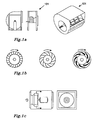
- the typical design solution for smaller low profile AHUs suitable for installation in a ceiling void is to use a crossflow heat exchanger for heat recovery and housed forward curved centrifugal fans, fig 1 a with a single fan inlet 101 as in (i) or with a double inlet as (ii) with the fan blades pointing forwards with the direction of fans rotation (forward curved) as in fig 1b (i) for the air movement.
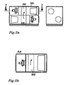
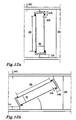
- a traditional packaged AHU with a perpendicular rotary heat exchanger (rotor) 202 design has a typical square shape (see fig 2a , showing a section through the centre of the unit, and fig 2b with is a section across the plane of A-A shown in fig 2a ).
- This design has a low ratio of flow capacity to unit height, see figure 3 . If this type of unit is sized to have a low enough profile to be installed in a ceiling void (of similar confined space) it would have a limited flow capacity that would only allow for relatively small ventilation rates. For example, at unit height of 600mm with an externally delivery pressure of 200 Pa, the flow capacity would be under 200 l/s (this data is extrapolated from figure 3 , data series (i).
- a design which offers a similar performance (energy efficiency, energy recovery and noise levels) to the larger central AHUs with a significantly reduced profile offering higher flow capacities relative to the unit's height will have significant advantages for energy savings and will give engineers/architects more flexibility in the ventilation system and building design. This is achieved with the AHU of the invention through the combination of an angled rotor heat exchanger, a centrifugal centrifugal plenum fan and a flow straightening structure.
- US patent 4727931 refers to a rotary heat exchanger that is inclined in a similar way to the present invention. What is different, however, and which makes the AHU of the present invention a much better design in terms of energy performance and a higher flow capacity to unit height ratio is the combined use of the centrifugal centrifugal plenum fan, optimisation of the frontal area of the rotor and in the use of a flow guiding (honeycomb) structure at the fans inlet.
- the focus of the present invention is therefore to provide an AHU specifically designed to have a low profile for use in tight spaces such as a ceiling void, wall void or floor void.
- installing a unit in such a space causes specific problems for serviceability of the unit.
- the Low profile AHU of the present invention presents flexible solutions to this dilemma providing sliding doors, alternative access entry points and further designs that allows for ease of removal and replacement to parts of the unit that require frequent access or maintenance in a safe manner
- the design employs sliding doors on the underside (when ceiling mounted) or side (when wall mounted), for easy access to filter, fan assembly and rotary heat exchanger's motor.
- the fan assembly has been designed especially for ease of removal and replacement in a safe manner.
- the filters can be replaced either by access from the sliding doors or from removable panels at the side of the unit.
- the invention relates to a low profile Air Handling Unit (AHU) enclosed in a casing comprising at least one rotary heat exchanger having one or more center areas (r) for air flow, air inlets, air outlets, air filters, access doors, fan enclosures, fan walls and centrifugal plenum fans with fan inlets having centre lines (q) and inlet opening diameters (d), said plenum fans producing an air flow through the AHU, wherein the at least one rotary heat exchanger is tilted at an angle of between 9 to 30° to the air flow direction through the unit; and wherein a flow straightening structure is placed at the inlet to the fans.
- AHU Air Handling Unit
- the at least one rotary heat exchanger is tilted at an angle of between 9 to 24° to the air flow direction through the unit.
- the at least one rotary heat exchanger is tilted at an angle of between 9 to 18° to the air flow direction through the unit.
- the flow straightening structure has a honeycomb cell structure.
- the honeycomb cell structure has a hydraulic diameter (D cell ) from 2 to 20mm and a cell length (T) of 2 to 30*D cell , the maximum length of the cell length being 0.2 x fan diameter or 100mm whichever is the shortest.
- the fan inlet opening diameter (d) is at least 0.92 times the centrifugal plenum fan diameter.
- the outer region of the fan inlet has a conic shape, such that the inside wall of said conic shaped fan inlet forms an angle ⁇ of between 30 to 45° to the fans centerline (q).
- the flow straightening structure is arranged at the conic shaped fan inlet.
- a flow guiding structure creates an angle ( ⁇ ) between 45 and 75° to the fan wall, at one or more sides of the flow straightening structure.
- the plenum fans are placed so that the centre lines (q) of the fan inlets are substantially vertically and horizontally aligned with the air flow through the respective centre areas (r) of the rotary heat exchanger.
- the one or more sound absorbing blocks are placed adjacent to the casing and the fan wall.
- the rotor in the rotary heat exchanger is one of the group comprising condensation and hygroscopic rotors.
- the access doors are sliding doors.
- the access doors are provided as one or more filter access panels are used to provide an alternative access route to the filter.
- the one or more fan guides rails and with an integrated retaining tab are used.
- a further aspect of the invention relates to the use of the low profile AHU for installation in confined spaces within a building, providing ventilation to such a building.
- LCC Life Cycle Cost
- fan diameter is largest diameter that the trailing edge of the fan blades at the outlet of the fan. This figure is commonly used to characteristic the size of a centrifugal fan.
- SFP Specific fan power
- V volume flow (l/s) for the greater of the supply or extract flows for the installation and Pe is electrical power (W) consumed by the whole AHU.
- BPF Blade Pass Frequency (Hz)
- n rotation velocity (n)
- t number of blades
- the term "hygroscopic treatment” enables the rotor gives the surface of the heat exchanger the ability to attract water molecules from the surrounding environment through either absorption or adsorption. This is used when one wishes to transfer humidity from one airstream to the other.
- DH hydroaulic diameter
- A the cross sectional area
- P the wetted perimeter of the cross-section.
- Rotary Heat Exchanger (other names: Heat wheel, Enthalpy wheel)
- Packaged air handling unit is intended to mean a unit providing balanced supply and extract ventilation which has all the necessary components (i.e. extract and supply fans, heat recovery, filters and control) integrated into one packaged unit.
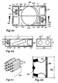
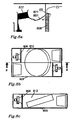
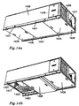
- Fig 4a shows a general plan view of a low profile AHU (400) of the invention.
- the casing 403 of an AHU has the shape of a rectangular box with the dimensions length (L) x width (W) x height (H), wherein the air flows through the unit in the longitudinal (L) direction.
- the height (H) of the casing is significantly reduced compared to typical prior art air handling units, as the AHU of the invention is sized to have a low enough profile to be installed in a confined space such as for example the ceiling or floor void. It will be shown that the flow capacities and ventilation rate of the AHU of the invention are comparable to those of traditional packaged AHU having a larger size.
- the casing 403 includes air inlets 404', 404" through which air enters the AHU and air outlets 405', 405" where from air exits the AHU (see figures 4a and 4b ).
- the casing 403, further includes one or more access doors (not shown), fan enclosures 413', 413", one or more air filters 464', 406" covering the air inlets 404', 404" on the inside of the casing 403.
- the air filters are generally composed of a fibrous material which removes solid particulates such as dust, pollen, mold, and bacteria from the air before it enters the AHU.
- the casing further comprises at least one rotary heat exchanger 402 (hereafter referred to as a rotor), one or more centrifugal plenum fans 407', 407" and one or more flow straightening structures 408', 408", all of which will be described in more detail below.
- the casing 403 may include one or more flow guiding structures 409', 409" and sound attenuating wedges 410', 410".
- Figure 4b shows a sectional plane (viewed from B-B in Fig. 4a ) through the centre of the rotor towards one half of the unit. Looking at the air flow from this view, the air would enter the AHU at the inlet 404', pass through the air filter 406' then through a filter plenum 411' and to the rotor 402'. Heat is exchanged between air and the rotor as the air passes through channels of the rotor.
- the air flows past the air filter 406" then through the filter plenum 411", to the rotor 402", to the inlet plenum 412", through the flow straightening structure 408" to the inlet of the fan 401 ", past the centrifugal plenum fan 407", through the fan enclosure 413" and to the AHU's outlet 405", where the air exits the AHU.
- the aim of the present invention is to provide an AHU specifically designed to have a low profile for use in such tight spaces with the minimum noise levels so that the unit can be used in close proximity to occupied spaces while at the same time provide an energy efficient solution comparable to that available for commercial centralised ventilation solutions.
- This objective is achieved by combining a centrifugal plenum fan of either backwards curved or airfoil type with a rotary heat exchanger that is tilted at an angle between 9 to 30° to the flow direction through the unit, (in the case of a ceiling void unit the rotor is tilted relative to the horizontal plane).
- a centrifugal plenum fan of either backwards curved or airfoil type
- a rotary heat exchanger that is tilted at an angle between 9 to 30° to the flow direction through the unit, (in the case of a ceiling void unit the rotor is tilted relative to the horizontal plane).
- Angling the rotor at an angle between 9 and 30° enables a unit with a significantly reduced height over that of the reference prior art unit, without incurring the penalty of large pressure loss that would result if the rotor was placed at an angle less than 9° to the horizontal.
- Angling the rotary heat exchanger between 9 and 30° also enables a rotary heat exchanger with a larger area to be used than the typical AHU, of the prior art, which has the benefits of reducing the pressure drop across the rotor.
- the rotary heat exchanger is preferably angled between 9 and 24°, and more preferably at an angle between 9 and 18° to the airflow direction through the unit,.
- a flow straightening structure 408 ( Fig. 4c ), is placed at the inlets 401 to the centrifugal plenum fans 407 ( figure 4d ).
- the flow straightening structure 408 is a matrix of short length passageways parallel to the fans centreline allowing the air to pass through. This has the effect of straightening the swirl in the flow through the inlet plenum 412 and in reducing the turbulent structures in the flow. The combined effect of this is that the fan noise is significantly reduced.
- the flow straightening structure 408 is a honeycomb cell structure
- the honeycomb structure has a cell size of 6.4mm figure 4c (i) and channel length of 30mm figure 4c (ii).
- the improvements are substantial.
- the sound power levels are almost identical to reference prior art unit of a square shape with a perpendicular rotor and with the same fan diameter providing the same flow and pressure capacity. Tests where undertaken with various sizes and lengths of honeycomb placed at the fans inlet, the results of which are shown in figures 5a and 5b . where the curves reference:
- FIG. 5a shows that the smaller cell size tested 3.2mm figure 5a curve (e) has the greatest sound improvement, however, due to the lower pressure loss, the 6.4mm cell figure 5a curve (d) was selected for the preferred embodiment.
- Figure 5b shows that lengthening the honeycomb cell structure over 20mm figure 5b curve (g) had little effect on the sound improvements.
- a 30mm channel length was chosen, however, for the preferred embodiment as a block of this length was more rigid and less flexible compared to the 20mm channel length.
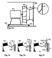
- the centrifugal plenum fan 607, fan inlet 601 and fan motor 614 are rigidity connected together by the motor assembly mounting frame 615 and mounted to the AHU casing 603 through vibration isolation dampers 616.
- Another possible mounting arrangement is where the centrifugal plenum fan 607 and motor 614 are mounted together and vibration isolated with the fan inlet 601 fixed directly to the fan wall 618 around the contact diameter shown in figure 6c as (i).
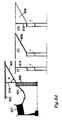
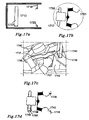
- FIG. 7a and 7b The fixation of the flow straightening structure at the inlet of the fan requires some careful consideration in order to not lose any advantages that the addition of a flow straightening structure gives.
- One embodiment of the invention ( Figure 7a and 7b ) is to place the flow straightening structure 708 directly on the fan's inlet 701. This placement is, however, not considered to be ideal as the performance of the centrifugal plenum fan is adversely affected due to the flow restriction caused by the acute angle that the fan's inlet 701 makes with the outflow face of the flow straightening structure 708 at position (i). This acute angle is made with traditional fan inlet shape which forms a tangent to the fan wall 718.
- An improved embodiment of the invention is to place the flow straightening structure 708 at a short distance from the fan inlet 701 with step up to a larger diameter marked (ii) in figure 7c where the ideal distance is such that that tangent to the fan inlet opening diameter marked d on figure 7c forms an angle ⁇ of between 30 and 45° to the centrifugal plenum fan's centre line marked (q).
- the fan inlet opening diameter (d) fig 7c should be at 0.92 times the centrifugal plenum fan diameter.
- a step up to larger diameter is naturally present when using a flexible cloth coupling 719 or sealing gasket 719 as shown in figure 7c and figure 6d .
- the preferred embodiment is to place the flow straightening structure 708 at the end of a conic fan inlet 721 where the outer region of the fan inlet 701 is changed to have a conic shape such that the inside wall of the fan inlet (721) forms an angle ⁇ of between 30 to 45° to the centrifugal plenum fans centreline (q).
- the fan inlet opening diameter shown as d in fig 7d is at least 0.92 times the centrifugal plenum fan diameter. This arrangement minimises the flow disturbance around in the periphery of the fans inlet 701 at the outlet of the flow straightening structure 708. This arrangement is optimal in terms of fan performance and sound reduction.
- a sealing gasket 720 shown figure 7e is placed at the end of the conic fan inlet 721 which is recessed at (i) such that the sealing gasket is flush with inlet so that the transition into the fan inlet is a smooth as practical.
- the sealing gasket 720 is so arranged that the positive pressure produced by the centrifugal plenum fan 707 pushes the sealing gasket at (ii) against the fan wall 718 thereby providing a good seal to minimise the leakage of air from the fan enclosure 713 to the inlet plenum 712.
- the fan wall is flush with the front of the flow straightening structure's 808 inlet face, which can be done by providing a recess in the fan wall 818, with a depth equal to the flow straightening structures 808 length L figure 8d (i) to hold the flow straightening structure 808.
- An improved embodiment would be to angle the fan wall 818, with an angle ( ⁇ ) of between 45 and 75°, adjacent to the flow straightening structures 808 at one or more sides to form a flow guiding structure 809 so that the flow would be better directed into the channels as shown in Figure 8d (ii).
- This flow guiding structure 809 could be a integral part of the fan wall as in option (ii) or this could made from a acoustic foam wedge such that it has a secondary function of absorb sound as shown in figure 8d (iii).
- the centrifugal plenum fan 907 and fan inlet 901 centre lines (q) are offset in both perpendicular directions from the centre line of the fan enclosure (p) and are as close as possible to alignment with the bulk flow from the rotor 902, line (q) whilst ensuring that the shortest distance between the fan blades to the plenum wall in the plane perpendicular to the fans centre line is greater than 0.1*fan diameter.
- the lines (q) are substantially vertically and horizontally aligned with the air flow that passes through the respective centres of the rotary heat exchangers area (r). This is done to maintain as uniform as possible flow to the fan's inlet and minimise the amount of swirl in the flow stream. This feature improves the pressure delivery by 20Pa for the reference invention unit with a sound improvement of 3dB.
- the fan inlet closer to the rotor outlets centreline when looking at the plan view of figure 9a allows more space to one side of the centrifugal plenum fan in the fan enclosure 913.
- the sound absorbing block has a triangular shape and is adjacent to the casing 1003 and the fan wall 1018. This serves two purposes; the first to help direct the air flow exiting from the centrifugal plenum fan and the second being to reduce the noise within the fan enclosure.
- the acoustic material (typically a mineral fibre or a synthetic foam) in the triangular shaped sound absorbing block 1010 reduces sound by direct absorption of a portion of the sound energy and secondly it blocks the direct path of the pressure pulsations generated from the outlet of the centrifugal plenum fan from reaching the side of the units casing 1003 immediate opposite the fans outlet in the largest flow path from the centrifugal plenum fan.
- This feature improves the pressure delivery at 430 l/s for the reference invention unit by 20Pa with an improvement to the noise levels by 5dB at the Blade passing frequency.
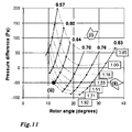
- Figure 11 shows the results from these simulations of performance of an AHU of the invention with a range of rotor diameters and rotor angles.
- Rotor width 200mm (industry standard width)
- the width of the unit was varied such that the ratio of the hydraulic diameter, for the centrifugal plenum fans housing in a section perpendicular to the fans centreline, to fan diameter was 1.9. This is a minimum recommended figure based of in-house testing of the centrifugal plenum fan. Below this value the performance of the centrifugal plenum fan drops off exponentially as the fan becomes confined by its enclosure. When the ratio of hydraulic diameter to fan diameter a ratio of 1.5 the airflow, the performance of the centrifugal plenum fan is reduced by 5% whereas with a ratio above1.9 there are only marginal gains in the centrifugal plenum fans airflow.
- the pressure difference in figure 11 is the difference in pressure losses predicted with an airflow of 430 l/s for the invention against the reference prior art unit.
- the rotor diameter ratio figure 11 (i) and the unit height ratio, figure 11 (ii) are the ratio of the invention dimension to that of the reference prior art unit.
- the constructed and tested invention AHU has a height of 500mm, however, to, provide flexibility in installation as the available space, for a typical ceiling void for example, varies from project to project then a number of AHU's of differing heights shall be offered. Following standard engineering standard practice the heights of this range of units would generally follow a geometric series.
- This invention uses a unique combination of the angled rotor with increased rotor area, a centrifugal plenum fan and flow straightening device at the inlet to create an AHU for use in confined spaces that provides higher flow delivery possibilities whilst providing a certain pressure and sound level.
- a rotary heat exchanger provides the best ratio of heat recovery efficiency to pressure drop for a specific face velocity of all heat exchanger types and so is the optimal choice when considering both energy recovery and the energy required from the centrifugal plenum fans to push the airflow through the heat exchanger.
- the rotary heat exchanger enables two differing types of rotors to be used: a condensation and a hydroscopic rotor.
- the condensation type is the most usual (typically of aluminium).
- a hydroscopic rotor (alternatively known as enthalpy rotor) has a hydroscopic coating (e.g. sulphates and silica gel) or a surface etching treatment that applied to the aluminum foil and moisture is transferred by pore sorption of moisture.
- a hydroscopic coating e.g. sulphates and silica gel
- a surface etching treatment that applied to the aluminum foil and moisture is transferred by pore sorption of moisture.
- a use of a rotor in the invention also then has the additional benefit of allowing for recovery of humidity and increasing the total energy recovered through latent heat recovery.
- the centrifugal plenum fan enables higher pressures to be delivered over a housed forward curved fan and less sensitive to outlet ducting placement due to the reduce outlet velocities.
- the performance capacity of a low profiled AHU can be reviewed by determining the maximum flow capability of the unit whilst providing a certain pressure, to drive the flow through the ducting and any connected ventilation components, whilst meeting a certain noise requirement that should not be exceeded.
- As the height of the unit will physically constrain the capacity of the unit it is useful to have a high a ratio of flow capacity to unit height.
- NR35 refers to the Noise Rating - NR - curves developed by the International Organization for Standardization (ISO) to determine the acceptable indoor noise levels.
- ISO International Organization for Standardization
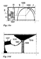
- Figure 13a shows a comparison of unit height against maximum flow rate that can be provided whilst providing a duct delivery pressure of 100Pa and meeting a sound to surroundings pressure level of NR35 plus 8dB of the reference invention and prior art units.
- Figure 13b shows a comparison of unit height against maximum flow rate that can be provided whilst providing a duct delivery pressure of 200Pa and meeting a sound to surroundings pressure level of NR35 plus 8dB of the reference invention and prior art units.
- the units height dimension is considered to be the minimum of the width or height of the unit since is it assumed that one can orient the unit to fit the confined space.
- point (i) is for the reference invention unit with a height (H) of 500mm with a rotor with a tilt angle of 12° and a rotor area that is twice the reference prior art units of figure 13 points (ii).
- Points (ii) are for two unit sizes in the range of the reference prior art units with a square AHU profile, a perpendicular rotor and a same fan diameter as the reference invention unit for the same flow and pressure capacity.
- Points (iii) represent competitor prior art units that are suitable for installations in confined spaces having a height under 800mm. These prior art units were of the following types:
- Figure 13a clearly shows that for a given height the flow capacity available whilst delivering 100Pa and meeting the NR35 + 8dB sound power requirement the flow capacity available from the reference unit invention is at least double than that of the competitor prior art units.
- Figure 13b shows that very little flow or no flow can be provide by competitor prior art units whilst delivering 200Pa and meeting the NR35 + 8dB sound power requirement.
- the invention also enables flexibility in the choice of installation as the invention has more available pressure to drive flow through a greater duct installation or an installation with more components
- the focus of the present invention is to provide an AHU specifically designed to have a low profile for use in tight spaces such as a ceiling void, wall void or floor void.
- installing a unit in such a space may cause specific problems for serviceability of the unit. This problem can also be further compounded if the access door swings outwards when opening.
- To take the filter from underneath can be difficult for example with a ceiling mounted unit when a ceiling tile framework or when other services (i.e. water piping, electrical, sprinkler systems, and lighting) are installed under the unit.
- sliding doors 1425 seen closed in figure 14a and with one open in figure14b , are provided to allow access to the fan assembly 1417, the filter 1406, and to the key maintenance points of the rotary heat exchanger assembly through the access panel 1426.
- This sliding door has a locking mechanism that when locked pulls the sliding door 1425 upwards compressing a foam covering 1427, shown in figure 14c , against the unit side wall 1428 forming an effective air tight seal.
- the door drops down and on rests in the groove 1430 formed by the angles of the sliding door guide 1431 by use of a bar extension 1432 allowing the door to be slid to the side for access to the unit.
- the rotary heat exchanger assembly 1522 comprises parts associated with the rotary heat exchanger, i.e.; rotary heat exchanger 1502 plus seals 1524, motor 1533, drive belt 1534 and speed sensor 1535, packaged in a framework 1522, figures 15a and 15b .
- a removable access panel 1536 as shown in figure 15a , is placed on one flow side of the rotary heat exchanger assembly 1522 so that access via the sliding door 1525 can be gained to the rotary heat exchanger's drive motor 1533, drive belt 1534 and speed sensor 1535 as seen in figure 15b for service inspection and maintenance.
- Access to the unit's filters are required so that the filter can be changed when dirty or as part of scheduled maintenance.
- Traditional units offer designs which allow for the filter to be changed from the underneath (when considering a ceiling void unit) or from the side. Both these variations can be limiting.
- To take the filter from underneath can be difficult when a ceiling tile framework or when other services (i.e. water piping, electrical, sprinkler systems, lighting) are installed under the unit.
- Removing the filter from the side can also be difficult when the unit is placed close to a wall or when other services (i.e. water piping, electrical, sprinkler systems, lighting) are placed to the side of the unit.
- One embodiment of the invention enables filter removal from two alternatives; from underneath (considering a ceiling mounted unit) and from the side.
- Removable filter access panels 1626 are set into the side of the unit to provide an alternative access point for filter 1606 replacement should access through the sliding doors 1625 be difficult due to some obstruction, for example; ceiling tile framework, lighting or other service fixtures being placed in the space under the unit.
- An embodiment of the invention provides a fan assembly design that allows for ease of removal and replacement in a safe manner.
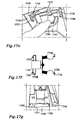
- fan guide rails 1737 and 1738 as shown in figures 17a to 17f are employed that allow the fans to be easily removed and replaced.
- the fan guide rail assembly consists of two guide sets per fan assembly. Each pair of guide set assemblies are comprised of a female fan guide rail 1737 and a male fan guide rail 1738.
- the female fan guide rail 1737 is mounted on the fan enclosure's side walls 1739, figure 17e and 17g , whilst the male fan guide rail 1738 is an integral part of the fan assembly 1717.
- the male fan guide rails 1738 are placed into the female guide rails 1737 at each side of the fan assembly 1717.
- the fan assembly is then guided into position as the fan is pushed into the unit as shown in figure 17b and 17c .
- the fan assembly is held at a slight angle from the fan wall 1718, as shown in figure 17d , so as to avoid snagging and potential damage on the seal 1720.
- the fan assembly 1717 is pushed inwards slightly and lowered into the correct position resting in the fan retaining tab 1740, figures 17f and 17g .
- the low profiled AHU of the invention will typically provide a balanced decentralised ventilation solution to a local area within a building with its installation being in a tight space, typically in the ceiling void or partitioned wall spaces, which would bring the unit in to close proximity to occupied spaces.
Landscapes
- Engineering & Computer Science (AREA)
- Chemical & Material Sciences (AREA)
- Combustion & Propulsion (AREA)
- Mechanical Engineering (AREA)
- General Engineering & Computer Science (AREA)
- Structures Of Non-Positive Displacement Pumps (AREA)
- Heat-Exchange Devices With Radiators And Conduit Assemblies (AREA)
Claims (16)
- Unité de traitement de l'air extra-plate (400) renfermée dans un boîtier (403) comprenant au moins un échangeur de chaleur rotatif (402) ayant une ou plusieurs régions centrales (r) pour l'écoulement d'air, des entrées d'air (404', 404"), des sorties d'air (405', 405"), des filtres à air (406', 406"), des portes d'accès (1425, 1626), des enceintes de ventilateurs (413', 413"), des parois de ventilateur (818) et des ventilateurs de répartition centrifuge (407', 407") avec des entrées de ventilateurs (401', 401") ayant des axes centraux (q) et des diamètres d'ouverture d'entrée (d), lesdits ventilateurs de répartition (407', 407") produisant un écoulement d'air dans l'unité de traitement de l'air, dans laquelle ledit au moins un échangeur de chaleur rotatif (402) est incliné en formant un angle de 9° à 30° avec la direction d'écoulement de l'air dans l'unité et dans laquelle une structure de redressement de l'écoulement (408', 408") est placée à l'entrée (401', 401") de chacun des ventilateurs (407', 407"), moyennant quoi l'air entre dans l'unité de traitement de l'air par l'entrée respective (404', 404"), passe à travers le filtre à air respectif (406', 406") puis à travers la chambre de répartition de filtre respective (411', 411") et atteint l'échangeur de chaleur rotatif (402), et où après être sorti de l'échangeur de chaleur rotatif (402), l'air traverse la chambre de répartition d'entrée respective (412', 412"), la structure de redressement de l'écoulement respective (408', 408") puis atteint l'entrée (401', 401") du ventilateur respectif (407', 407"), traverse l'enceinte de ventilateur respective (413', 413") puis sort de l'unité de traitement de l'air par la sortie respective (405', 405").
- Unité de traitement de l'air extra-plate selon la revendication 1, dans laquelle ledit au moins un échangeur de chaleur rotatif (402) est incliné en formant un angle de 9° à 24° avec la direction d'écoulement de l'air dans l'unité.
- Unité de traitement de l'air extra-plate selon la revendication 1, dans laquelle ledit au moins un échangeur de chaleur rotatif (402) est incliné en formant un angle de 9° à 18° avec la direction d'écoulement de l'air dans l'unité.
- Unité de traitement de l'air extra-plate selon la revendication 1, dans laquelle la structure de redressement de l'écoulement (408) a une structure en nid d'abeilles.
- Unité de traitement de l'air extra-plate selon la revendication 4, dans laquelle la structure en nid d'abeilles a un diamètre hydraulique (Dcell) de 2 à 20 mm et une longueur de cellule (T) de 2 à 30*Dcell, la longueur maximale de la cellule étant égale à 0,2 x le diamètre du ventilateur ou 100 mm, quelle que soit la plus petite des deux valeurs.
- Unité de traitement de l'air extra-plate selon la revendication 1, dans laquelle le diamètre d'entrée de ventilateur (d) vaut au moins 0,92 fois le diamètre du ventilateur de répartition centrifuge.
- Unité de traitement de l'air extra-plate selon la revendication 1, dans laquelle une région extérieure de l'entrée de ventilateur (401) a une forme conique (721), de sorte que la paroi intérieure de ladite entrée de ventilateur de forme conique (721) forme un angle ϕ de 30° à 45° avec l'axe central du ventilateur (q).
- Unité de traitement de l'air extra-plate selon la revendication 7, dans laquelle la structure de redressement de l'écoulement (708) est placée au niveau de l'entrée de ventilateur de forme conique (721).
- Unité de traitement de l'air extra-plate selon la revendication 1, dans laquelle une structure de guidage d'écoulement (809) créée un angle (ψ) de 45° à 75° avec la paroi de ventilateur (818), sur un ou plusieurs côtés de la structure de redressement de l'écoulement (808).
- Unité de traitement de l'air extra-plate selon la revendication 1, dans laquelle les ventilateurs de répartition (907) sont placés de telle manière que les axes centraux (q) des entrées de ventilateurs (901) sont substantiellement alignés verticalement et horizontalement avec l'écoulement d'air traversant les régions centrales respectives (r) de l'échangeur de chaleur rotatif (902).
- Unité de traitement de l'air extra-plate selon la revendication 1, dans laquelle un ou plusieurs blocs absorbants acoustiques (1010) sont placés en position adjacente au boîtier (1003) et à la paroi de ventilateur (1018).
- Unité de traitement de l'air extra-plate selon la revendication 1, dans laquelle le rotor de l'échangeur de chaleur rotatif (402) est choisi dans le groupe comprenant les rotors de condensation et les rotors hygroscopiques.
- Unité de traitement de l'air extra-plate selon la revendication 1, dans laquelle les portes d'accès sont des portes coulissantes (1425).
- Unité de traitement de l'air extra-plate selon la revendication 1, dans laquelle les portes d'accès se présentent sous la forme d'une ou de plusieurs portes d'accès à un filtre (1626) qui sont utilisées pour fournir un autre chemin d'accès au filtre.
- Unité de traitement de l'air extra-plate selon la revendication 1, dans laquelle un ou plusieurs rails de guidage de ventilateur (1737) et (1738) ayant une patte de retenue intégrée (1740) sont utilisés.
- Utilisation de l'unité de traitement de l'air extra-plate selon les revendications 1 à 15 pour une installation dans des espaces confinés à l'intérieur d'un bâtiment, fournissant une ventilation à ce bâtiment.
Applications Claiming Priority (4)
| Application Number | Priority Date | Filing Date | Title |
|---|---|---|---|
| SE0950026 | 2009-01-23 | ||
| SE0950025 | 2009-01-23 | ||
| SE0901124 | 2009-08-26 | ||
| PCT/SE2010/000016 WO2010085197A2 (fr) | 2009-01-23 | 2010-01-25 | Unité de traitement de l'air à profil bas avec échangeur de chaleur tournant incliné |
Publications (2)
| Publication Number | Publication Date |
|---|---|
| EP2382425A2 EP2382425A2 (fr) | 2011-11-02 |
| EP2382425B1 true EP2382425B1 (fr) | 2013-08-28 |
Family
ID=42356361
Family Applications (1)
| Application Number | Title | Priority Date | Filing Date |
|---|---|---|---|
| EP10728442.4A Not-in-force EP2382425B1 (fr) | 2009-01-23 | 2010-01-25 | Unité de traitement de l'air à profil bas avec échangeur de chaleur tournant incliné |
Country Status (2)
| Country | Link |
|---|---|
| EP (1) | EP2382425B1 (fr) |
| WO (1) | WO2010085197A2 (fr) |
Cited By (3)
| Publication number | Priority date | Publication date | Assignee | Title |
|---|---|---|---|---|
| US10890352B2 (en) | 2016-03-10 | 2021-01-12 | Carrier Corporation | Air handling unit |
| EP4109024A1 (fr) * | 2021-06-25 | 2022-12-28 | Carrier Corporation | Ventilateur intégral à récupération d'énergie avec dérivation par rotation pour les toits |
| EP4614080A4 (fr) * | 2022-10-31 | 2026-01-14 | Gd Midea Heating & Ventilating Equipment Co Ltd | Appareil de traitement d'air |
Families Citing this family (4)
| Publication number | Priority date | Publication date | Assignee | Title |
|---|---|---|---|---|
| WO2012011865A2 (fr) | 2010-07-23 | 2012-01-26 | Swegon Ab | Unité de traitement d'air dotée d'une dérivation vers l'échangeur thermique rotatif |
| ES2353291B1 (es) * | 2010-10-26 | 2012-01-24 | Servifiltro, S.L. | Equipo con estructura modular simplificada de fácil montaje para ventilación/tratamiento de aire con recuperador térmico estático. |
| DE202011104662U1 (de) | 2011-08-03 | 2011-12-05 | LUNOS Lüftungstechnik GmbH für Raumluftsysteme | Einbauprofil |
| BE1024294B1 (nl) * | 2016-06-14 | 2018-01-23 | Erik Wilms | Ventilatie-unit |
Family Cites Families (8)
| Publication number | Priority date | Publication date | Assignee | Title |
|---|---|---|---|---|
| US3748997A (en) * | 1972-04-06 | 1973-07-31 | Tempmaster Corp | Acoustical insulated fan and temperature conditioning penthouse unit |
| US4727931A (en) | 1985-06-19 | 1988-03-01 | Erling Berner | Air exchanging apparatus and method |
| US5826641A (en) * | 1994-10-27 | 1998-10-27 | Aaon, Inc. | Air conditioner with heat wheel |
| DE19641318A1 (de) * | 1996-10-08 | 1998-05-14 | Oleg Stolz | Regenerativer Wärmetauscher |
| JP2005009727A (ja) * | 2003-06-18 | 2005-01-13 | Seibu Giken Co Ltd | 除湿空調装置 |
| JP2005042955A (ja) * | 2003-07-24 | 2005-02-17 | Max Co Ltd | 換気装置および該換気装置を備えた住宅構造 |
| FR2863040B1 (fr) * | 2003-11-28 | 2007-04-13 | Hydronic Sa | Centrale de traitement d'air equipee d'un espace de degagement au niveau duquel sont regroupes des moyens de raccordement des moyens echangeurs de chaleur |
| US7484381B2 (en) * | 2004-07-09 | 2009-02-03 | Spinnaker Industries Inc. | Energy recovery unit |
-
2010
- 2010-01-25 WO PCT/SE2010/000016 patent/WO2010085197A2/fr not_active Ceased
- 2010-01-25 EP EP10728442.4A patent/EP2382425B1/fr not_active Not-in-force
Cited By (3)
| Publication number | Priority date | Publication date | Assignee | Title |
|---|---|---|---|---|
| US10890352B2 (en) | 2016-03-10 | 2021-01-12 | Carrier Corporation | Air handling unit |
| EP4109024A1 (fr) * | 2021-06-25 | 2022-12-28 | Carrier Corporation | Ventilateur intégral à récupération d'énergie avec dérivation par rotation pour les toits |
| EP4614080A4 (fr) * | 2022-10-31 | 2026-01-14 | Gd Midea Heating & Ventilating Equipment Co Ltd | Appareil de traitement d'air |
Also Published As
| Publication number | Publication date |
|---|---|
| WO2010085197A3 (fr) | 2011-01-06 |
| WO2010085197A8 (fr) | 2011-06-30 |
| WO2010085197A2 (fr) | 2010-07-29 |
| EP2382425A2 (fr) | 2011-11-02 |
Similar Documents
| Publication | Publication Date | Title |
|---|---|---|
| EP2382425B1 (fr) | Unité de traitement de l'air à profil bas avec échangeur de chaleur tournant incliné | |
| US10775074B2 (en) | Sound attenuating air handler panel apparatus and method | |
| EP0940585B1 (fr) | Coude d'aspiration muni d'aubes de guidage integrees | |
| EP2764297A2 (fr) | Installation de traitement de l'air à construction intégrée, pour système de refroidissement de batterie de serveurs | |
| CN102906509B (zh) | 用于窗户的具有热导管的通风设备 | |
| WO2012011865A2 (fr) | Unité de traitement d'air dotée d'une dérivation vers l'échangeur thermique rotatif | |
| RU2531735C2 (ru) | Вентиляционное устройство для окон | |
| KR20190009585A (ko) | 환기장치용 케이싱 및 그것을 구비한 열회수형 환기장치 | |
| US7603873B2 (en) | Enbloc air conditioner | |
| WO2009003472A1 (fr) | Module de refroidissement pour des systèmes de ventilation disposés de façon décentrée | |
| KR20160031657A (ko) | 열회수형 환기장치용 분배박스 및 이를 구비한 열회수형 환기장치 | |
| KR101901174B1 (ko) | 고성능 흡음형 소음기 | |
| US20240019164A1 (en) | Multifunction panel | |
| Liu et al. | Impacts of static pressure set level on the HVAC energy consumption and indoor conditions | |
| CN101428188B (zh) | 侧进风超薄风机过滤单元 | |
| CN102906508B (zh) | 用于窗户的通风设备的热交换设备以及具有该热交换设备的热交换模块 | |
| JP5521648B2 (ja) | 消音ボックス付送風機 | |
| JP2007285584A (ja) | 換気装置 | |
| CN109681995A (zh) | 一种核电站组合式空调机组 | |
| CN206683080U (zh) | 一种基站空调 | |
| KR100946587B1 (ko) | 열교환 환풍기 | |
| CN223050245U (zh) | 一种单模块空气源热泵装置 | |
| JP7606795B1 (ja) | 空調用部品セット、空調用部品、空調システム及び建築物 | |
| KR200367863Y1 (ko) | 빌트업 공기조화기를 위한 조립식 보온패널 구조체 | |
| JP2857584B2 (ja) | 熱交換器 |
Legal Events
| Date | Code | Title | Description |
|---|---|---|---|
| PUAI | Public reference made under article 153(3) epc to a published international application that has entered the european phase |
Free format text: ORIGINAL CODE: 0009012 |
|
| 17P | Request for examination filed |
Effective date: 20110708 |
|
| AK | Designated contracting states |
Kind code of ref document: A2 Designated state(s): AT BE BG CH CY CZ DE DK EE ES FI FR GB GR HR HU IE IS IT LI LT LU LV MC MK MT NL NO PL PT RO SE SI SK SM TR |
|
| DAX | Request for extension of the european patent (deleted) | ||
| GRAP | Despatch of communication of intention to grant a patent |
Free format text: ORIGINAL CODE: EPIDOSNIGR1 |
|
| GRAS | Grant fee paid |
Free format text: ORIGINAL CODE: EPIDOSNIGR3 |
|
| GRAA | (expected) grant |
Free format text: ORIGINAL CODE: 0009210 |
|
| AK | Designated contracting states |
Kind code of ref document: B1 Designated state(s): AT BE BG CH CY CZ DE DK EE ES FI FR GB GR HR HU IE IS IT LI LT LU LV MC MK MT NL NO PL PT RO SE SI SK SM TR |
|
| REG | Reference to a national code |
Ref country code: GB Ref legal event code: FG4D |
|
| REG | Reference to a national code |
Ref country code: CH Ref legal event code: EP |
|
| REG | Reference to a national code |
Ref country code: AT Ref legal event code: REF Ref document number: 629574 Country of ref document: AT Kind code of ref document: T Effective date: 20130915 |
|
| REG | Reference to a national code |
Ref country code: IE Ref legal event code: FG4D |
|
| REG | Reference to a national code |
Ref country code: DE Ref legal event code: R096 Ref document number: 602010009799 Country of ref document: DE Effective date: 20131024 |
|
| REG | Reference to a national code |
Ref country code: SE Ref legal event code: TRGR |
|
| REG | Reference to a national code |
Ref country code: AT Ref legal event code: MK05 Ref document number: 629574 Country of ref document: AT Kind code of ref document: T Effective date: 20130828 |
|
| REG | Reference to a national code |
Ref country code: LT Ref legal event code: MG4D |
|
| REG | Reference to a national code |
Ref country code: NL Ref legal event code: VDEP Effective date: 20130828 |
|
| PG25 | Lapsed in a contracting state [announced via postgrant information from national office to epo] |
Ref country code: AT Free format text: LAPSE BECAUSE OF FAILURE TO SUBMIT A TRANSLATION OF THE DESCRIPTION OR TO PAY THE FEE WITHIN THE PRESCRIBED TIME-LIMIT Effective date: 20130828 Ref country code: IS Free format text: LAPSE BECAUSE OF FAILURE TO SUBMIT A TRANSLATION OF THE DESCRIPTION OR TO PAY THE FEE WITHIN THE PRESCRIBED TIME-LIMIT Effective date: 20131228 Ref country code: PT Free format text: LAPSE BECAUSE OF FAILURE TO SUBMIT A TRANSLATION OF THE DESCRIPTION OR TO PAY THE FEE WITHIN THE PRESCRIBED TIME-LIMIT Effective date: 20131230 Ref country code: LT Free format text: LAPSE BECAUSE OF FAILURE TO SUBMIT A TRANSLATION OF THE DESCRIPTION OR TO PAY THE FEE WITHIN THE PRESCRIBED TIME-LIMIT Effective date: 20130828 Ref country code: NO Free format text: LAPSE BECAUSE OF FAILURE TO SUBMIT A TRANSLATION OF THE DESCRIPTION OR TO PAY THE FEE WITHIN THE PRESCRIBED TIME-LIMIT Effective date: 20131128 Ref country code: CY Free format text: LAPSE BECAUSE OF FAILURE TO SUBMIT A TRANSLATION OF THE DESCRIPTION OR TO PAY THE FEE WITHIN THE PRESCRIBED TIME-LIMIT Effective date: 20130724 Ref country code: HR Free format text: LAPSE BECAUSE OF FAILURE TO SUBMIT A TRANSLATION OF THE DESCRIPTION OR TO PAY THE FEE WITHIN THE PRESCRIBED TIME-LIMIT Effective date: 20130828 |
|
| REG | Reference to a national code |
Ref country code: NL Ref legal event code: VDEP Effective date: 20130828 |
|
| PG25 | Lapsed in a contracting state [announced via postgrant information from national office to epo] |
Ref country code: PL Free format text: LAPSE BECAUSE OF FAILURE TO SUBMIT A TRANSLATION OF THE DESCRIPTION OR TO PAY THE FEE WITHIN THE PRESCRIBED TIME-LIMIT Effective date: 20130828 Ref country code: BE Free format text: LAPSE BECAUSE OF FAILURE TO SUBMIT A TRANSLATION OF THE DESCRIPTION OR TO PAY THE FEE WITHIN THE PRESCRIBED TIME-LIMIT Effective date: 20130828 Ref country code: LV Free format text: LAPSE BECAUSE OF FAILURE TO SUBMIT A TRANSLATION OF THE DESCRIPTION OR TO PAY THE FEE WITHIN THE PRESCRIBED TIME-LIMIT Effective date: 20130828 Ref country code: GR Free format text: LAPSE BECAUSE OF FAILURE TO SUBMIT A TRANSLATION OF THE DESCRIPTION OR TO PAY THE FEE WITHIN THE PRESCRIBED TIME-LIMIT Effective date: 20131129 Ref country code: FI Free format text: LAPSE BECAUSE OF FAILURE TO SUBMIT A TRANSLATION OF THE DESCRIPTION OR TO PAY THE FEE WITHIN THE PRESCRIBED TIME-LIMIT Effective date: 20130828 Ref country code: SI Free format text: LAPSE BECAUSE OF FAILURE TO SUBMIT A TRANSLATION OF THE DESCRIPTION OR TO PAY THE FEE WITHIN THE PRESCRIBED TIME-LIMIT Effective date: 20130828 |
|
| PG25 | Lapsed in a contracting state [announced via postgrant information from national office to epo] |
Ref country code: CY Free format text: LAPSE BECAUSE OF FAILURE TO SUBMIT A TRANSLATION OF THE DESCRIPTION OR TO PAY THE FEE WITHIN THE PRESCRIBED TIME-LIMIT Effective date: 20130828 |
|
| PG25 | Lapsed in a contracting state [announced via postgrant information from national office to epo] |
Ref country code: CZ Free format text: LAPSE BECAUSE OF FAILURE TO SUBMIT A TRANSLATION OF THE DESCRIPTION OR TO PAY THE FEE WITHIN THE PRESCRIBED TIME-LIMIT Effective date: 20130828 Ref country code: NL Free format text: LAPSE BECAUSE OF FAILURE TO SUBMIT A TRANSLATION OF THE DESCRIPTION OR TO PAY THE FEE WITHIN THE PRESCRIBED TIME-LIMIT Effective date: 20130828 Ref country code: SK Free format text: LAPSE BECAUSE OF FAILURE TO SUBMIT A TRANSLATION OF THE DESCRIPTION OR TO PAY THE FEE WITHIN THE PRESCRIBED TIME-LIMIT Effective date: 20130828 Ref country code: EE Free format text: LAPSE BECAUSE OF FAILURE TO SUBMIT A TRANSLATION OF THE DESCRIPTION OR TO PAY THE FEE WITHIN THE PRESCRIBED TIME-LIMIT Effective date: 20130828 Ref country code: RO Free format text: LAPSE BECAUSE OF FAILURE TO SUBMIT A TRANSLATION OF THE DESCRIPTION OR TO PAY THE FEE WITHIN THE PRESCRIBED TIME-LIMIT Effective date: 20130828 Ref country code: DK Free format text: LAPSE BECAUSE OF FAILURE TO SUBMIT A TRANSLATION OF THE DESCRIPTION OR TO PAY THE FEE WITHIN THE PRESCRIBED TIME-LIMIT Effective date: 20130828 |
|
| PG25 | Lapsed in a contracting state [announced via postgrant information from national office to epo] |
Ref country code: IT Free format text: LAPSE BECAUSE OF FAILURE TO SUBMIT A TRANSLATION OF THE DESCRIPTION OR TO PAY THE FEE WITHIN THE PRESCRIBED TIME-LIMIT Effective date: 20130828 Ref country code: ES Free format text: LAPSE BECAUSE OF FAILURE TO SUBMIT A TRANSLATION OF THE DESCRIPTION OR TO PAY THE FEE WITHIN THE PRESCRIBED TIME-LIMIT Effective date: 20130828 |
|
| REG | Reference to a national code |
Ref country code: DE Ref legal event code: R097 Ref document number: 602010009799 Country of ref document: DE |
|
| PLBE | No opposition filed within time limit |
Free format text: ORIGINAL CODE: 0009261 |
|
| STAA | Information on the status of an ep patent application or granted ep patent |
Free format text: STATUS: NO OPPOSITION FILED WITHIN TIME LIMIT |
|
| 26N | No opposition filed |
Effective date: 20140530 |
|
| PG25 | Lapsed in a contracting state [announced via postgrant information from national office to epo] |
Ref country code: LU Free format text: LAPSE BECAUSE OF FAILURE TO SUBMIT A TRANSLATION OF THE DESCRIPTION OR TO PAY THE FEE WITHIN THE PRESCRIBED TIME-LIMIT Effective date: 20140125 |
|
| REG | Reference to a national code |
Ref country code: CH Ref legal event code: PL |
|
| REG | Reference to a national code |
Ref country code: DE Ref legal event code: R097 Ref document number: 602010009799 Country of ref document: DE Effective date: 20140530 |
|
| PG25 | Lapsed in a contracting state [announced via postgrant information from national office to epo] |
Ref country code: CH Free format text: LAPSE BECAUSE OF NON-PAYMENT OF DUE FEES Effective date: 20140131 Ref country code: LI Free format text: LAPSE BECAUSE OF NON-PAYMENT OF DUE FEES Effective date: 20140131 |
|
| REG | Reference to a national code |
Ref country code: FR Ref legal event code: ST Effective date: 20140930 |
|
| REG | Reference to a national code |
Ref country code: IE Ref legal event code: MM4A |
|
| PG25 | Lapsed in a contracting state [announced via postgrant information from national office to epo] |
Ref country code: FR Free format text: LAPSE BECAUSE OF NON-PAYMENT OF DUE FEES Effective date: 20140131 |
|
| PG25 | Lapsed in a contracting state [announced via postgrant information from national office to epo] |
Ref country code: IE Free format text: LAPSE BECAUSE OF NON-PAYMENT OF DUE FEES Effective date: 20140125 |
|
| PG25 | Lapsed in a contracting state [announced via postgrant information from national office to epo] |
Ref country code: MC Free format text: LAPSE BECAUSE OF FAILURE TO SUBMIT A TRANSLATION OF THE DESCRIPTION OR TO PAY THE FEE WITHIN THE PRESCRIBED TIME-LIMIT Effective date: 20130828 |
|
| PG25 | Lapsed in a contracting state [announced via postgrant information from national office to epo] |
Ref country code: MT Free format text: LAPSE BECAUSE OF FAILURE TO SUBMIT A TRANSLATION OF THE DESCRIPTION OR TO PAY THE FEE WITHIN THE PRESCRIBED TIME-LIMIT Effective date: 20130828 |
|
| PG25 | Lapsed in a contracting state [announced via postgrant information from national office to epo] |
Ref country code: SM Free format text: LAPSE BECAUSE OF FAILURE TO SUBMIT A TRANSLATION OF THE DESCRIPTION OR TO PAY THE FEE WITHIN THE PRESCRIBED TIME-LIMIT Effective date: 20130828 |
|
| PG25 | Lapsed in a contracting state [announced via postgrant information from national office to epo] |
Ref country code: BG Free format text: LAPSE BECAUSE OF FAILURE TO SUBMIT A TRANSLATION OF THE DESCRIPTION OR TO PAY THE FEE WITHIN THE PRESCRIBED TIME-LIMIT Effective date: 20130828 |
|
| PG25 | Lapsed in a contracting state [announced via postgrant information from national office to epo] |
Ref country code: HU Free format text: LAPSE BECAUSE OF FAILURE TO SUBMIT A TRANSLATION OF THE DESCRIPTION OR TO PAY THE FEE WITHIN THE PRESCRIBED TIME-LIMIT; INVALID AB INITIO Effective date: 20100125 |
|
| PG25 | Lapsed in a contracting state [announced via postgrant information from national office to epo] |
Ref country code: MK Free format text: LAPSE BECAUSE OF FAILURE TO SUBMIT A TRANSLATION OF THE DESCRIPTION OR TO PAY THE FEE WITHIN THE PRESCRIBED TIME-LIMIT Effective date: 20130828 |
|
| PGFP | Annual fee paid to national office [announced via postgrant information from national office to epo] |
Ref country code: GB Payment date: 20200109 Year of fee payment: 11 Ref country code: DE Payment date: 20200109 Year of fee payment: 11 Ref country code: SE Payment date: 20200116 Year of fee payment: 11 |
|
| PGFP | Annual fee paid to national office [announced via postgrant information from national office to epo] |
Ref country code: TR Payment date: 20200113 Year of fee payment: 11 |
|
| REG | Reference to a national code |
Ref country code: DE Ref legal event code: R119 Ref document number: 602010009799 Country of ref document: DE |
|
| REG | Reference to a national code |
Ref country code: SE Ref legal event code: EUG |
|
| GBPC | Gb: european patent ceased through non-payment of renewal fee |
Effective date: 20210125 |
|
| PG25 | Lapsed in a contracting state [announced via postgrant information from national office to epo] |
Ref country code: DE Free format text: LAPSE BECAUSE OF NON-PAYMENT OF DUE FEES Effective date: 20210803 Ref country code: GB Free format text: LAPSE BECAUSE OF NON-PAYMENT OF DUE FEES Effective date: 20210125 Ref country code: SE Free format text: LAPSE BECAUSE OF NON-PAYMENT OF DUE FEES Effective date: 20210126 |
|
| PG25 | Lapsed in a contracting state [announced via postgrant information from national office to epo] |
Ref country code: TR Free format text: LAPSE BECAUSE OF NON-PAYMENT OF DUE FEES Effective date: 20210125 |