EP2381290A1 - Optischer Wellenleiter und Anzeigevorrichtung - Google Patents
Optischer Wellenleiter und Anzeigevorrichtung Download PDFInfo
- Publication number
- EP2381290A1 EP2381290A1 EP10275047A EP10275047A EP2381290A1 EP 2381290 A1 EP2381290 A1 EP 2381290A1 EP 10275047 A EP10275047 A EP 10275047A EP 10275047 A EP10275047 A EP 10275047A EP 2381290 A1 EP2381290 A1 EP 2381290A1
- Authority
- EP
- European Patent Office
- Prior art keywords
- spectral portion
- image
- expanding
- layer
- colour component
- Prior art date
- Legal status (The legal status is an assumption and is not a legal conclusion. Google has not performed a legal analysis and makes no representation as to the accuracy of the status listed.)
- Ceased
Links
Images


Classifications
-
- G—PHYSICS
- G02—OPTICS
- G02B—OPTICAL ELEMENTS, SYSTEMS OR APPARATUS
- G02B27/00—Optical systems or apparatus not provided for by any of the groups G02B1/00 - G02B26/00, G02B30/00
- G02B27/10—Beam splitting or combining systems
- G02B27/1086—Beam splitting or combining systems operating by diffraction only
-
- G—PHYSICS
- G02—OPTICS
- G02B—OPTICAL ELEMENTS, SYSTEMS OR APPARATUS
- G02B27/00—Optical systems or apparatus not provided for by any of the groups G02B1/00 - G02B26/00, G02B30/00
- G02B27/10—Beam splitting or combining systems
- G02B27/14—Beam splitting or combining systems operating by reflection only
- G02B27/141—Beam splitting or combining systems operating by reflection only using dichroic mirrors
-
- G—PHYSICS
- G02—OPTICS
- G02B—OPTICAL ELEMENTS, SYSTEMS OR APPARATUS
- G02B27/00—Optical systems or apparatus not provided for by any of the groups G02B1/00 - G02B26/00, G02B30/00
- G02B27/10—Beam splitting or combining systems
- G02B27/14—Beam splitting or combining systems operating by reflection only
- G02B27/142—Coating structures, e.g. thin films multilayers
-
- G—PHYSICS
- G02—OPTICS
- G02B—OPTICAL ELEMENTS, SYSTEMS OR APPARATUS
- G02B27/00—Optical systems or apparatus not provided for by any of the groups G02B1/00 - G02B26/00, G02B30/00
- G02B27/01—Head-up displays
- G02B27/0101—Head-up displays characterised by optical features
- G02B2027/0112—Head-up displays characterised by optical features comprising device for genereting colour display
-
- G—PHYSICS
- G02—OPTICS
- G02B—OPTICAL ELEMENTS, SYSTEMS OR APPARATUS
- G02B5/00—Optical elements other than lenses
- G02B5/18—Diffraction gratings
-
- G—PHYSICS
- G02—OPTICS
- G02B—OPTICAL ELEMENTS, SYSTEMS OR APPARATUS
- G02B6/00—Light guides; Structural details of arrangements comprising light guides and other optical elements, e.g. couplings
-
- G—PHYSICS
- G02—OPTICS
- G02B—OPTICAL ELEMENTS, SYSTEMS OR APPARATUS
- G02B6/00—Light guides; Structural details of arrangements comprising light guides and other optical elements, e.g. couplings
- G02B6/0001—Light guides; Structural details of arrangements comprising light guides and other optical elements, e.g. couplings specially adapted for lighting devices or systems
- G02B6/0011—Light guides; Structural details of arrangements comprising light guides and other optical elements, e.g. couplings specially adapted for lighting devices or systems the light guides being planar or of plate-like form
- G02B6/0033—Means for improving the coupling-out of light from the light guide
- G02B6/0035—Means for improving the coupling-out of light from the light guide provided on the surface of the light guide or in the bulk of it
-
- G—PHYSICS
- G02—OPTICS
- G02B—OPTICAL ELEMENTS, SYSTEMS OR APPARATUS
- G02B6/00—Light guides; Structural details of arrangements comprising light guides and other optical elements, e.g. couplings
- G02B6/0001—Light guides; Structural details of arrangements comprising light guides and other optical elements, e.g. couplings specially adapted for lighting devices or systems
- G02B6/0011—Light guides; Structural details of arrangements comprising light guides and other optical elements, e.g. couplings specially adapted for lighting devices or systems the light guides being planar or of plate-like form
- G02B6/0075—Arrangements of multiple light guides
- G02B6/0076—Stacked arrangements of multiple light guides of the same or different cross-sectional area
Definitions
- This invention relates to an optical waveguide and a display device.
- it is relevant to display devices in which image bearing light is injected into a waveguide, is expanded therein e.g. by diffraction gratings, in two orthogonal dimensions to form a visible image and is released from the waveguide.
- Such devices which use a single waveguide, for example as shown in US6509529 , can be optimised only for one part of the visible spectrum. Usually the middle part of the spectrum is chosen, with the result that the display has a strong greenish hue.
- Each waveguide is optimised for a different one of the three primary colours red, green and blue.
- the outputs of the three waveguides are then additionally combined to form an approximately full-colour display.
- Such a device has the disadvantages of complexity and cost, since three waveguides are required, and the further disadvantage of weight and bulk, which in particularly undesirable in head-mounted or helmet-mounted displays.
- a full-colour solution is obtainable using a three-layer stacked volume grating in a single waveguide ( US7418170 ) but such gratings are difficult to manufacture in quantity, and are consequently expensive.
- the present invention at least in its preferred embodiments seeks to reduce some or all of the disadvantages of the prior art.
- the invention provides an optical method of displaying an expanded colour image comprising extracting from input light bearing said coloured image a first spectral portion and a second spectral portion such that together the two portions contain sufficient information for the image to be displayed in substantially its original colours, separately expanding the two spectral portions each in two dimensions and recombining the expanded spectral portions to display the expanded colour image.
- the invention provides an optical structure for the transmission of light input thereto bearing a colour image, comprising means for extracting from the input light a first spectral portion and a second spectral portion such that together the two portions contain sufficient information for light outputted by the structure to display the image in substantially its original colours, a first expanding means for expanding the first spectral portion in two dimensions, a second expanding means for expanding the second spectral portion in two dimensions and means for combining the expanded first and second spectral portions to display the colour image.
- the extracting means may be configured to extract as said first spectral portion at least a majority of a first primary colour component of the input light, part of a second primary colour component thereof and a minority of a third primary colour component thereof, and to extract as said second spectral portion a minority of the first primary colour component, part of the second primary colour component and at least the majority of the third primary colour component.
- the extracting means may comprise a first diffraction grating or other diffracting means for extracting the first spectral portion, and a second diffraction grating or other diffracting means for extracting the second spectral portion, the first and second diffracting means having periodic diffracting patterns of different pitch.
- the first diffracting means may be adapted to reflect the first spectral portion and to transmit the second spectral portion.
- the first diffracting means may comprise at least one coating layer on the diffracting pattern, the thickness and composition of the or each layer being such that interferences between reflections of at least the first primary colour component from some of the interfaces between the layers and/or between a said layer and another medium are constructive.
- the said coating layers on the first diffracting means may comprise a layer of silicon dioxide and a layer of titanium dioxide.
- the second diffracting means may comprise a reflective layer and at least one coating layer, the thickness and composition of the or each such layer being such that interferences between reflections of at least the third primary colour component from the reflective layer and from at least one interface between the layers or between a said layer and another medium are constructive.
- the reflective coating on the second diffracting means may comprise a layer of silver, and the coating layer thereon must by of titanium dioxide.
- the two expanding means may be disposed relative to each other so that in operation the expanded first spectral portion passes from the first expanding means through the second expanding means, and the expanded first and second spectral portions are thereby combined as said image.
- a said expanding means may be a waveguide comprises a first diffracting means for expanding a said spectral portion in the first dimension and a second diffracting means for expanding the said spectral portion in the second dimension.
- the second diffracting means of the second expanding means may be adapted to combine the expanded first and second portions as said image.
- the invention also provides a helmet-mounted display, a head-up display or another display system comprising an optical structure or configured to implement a method as set forth above.
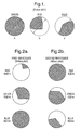
- Figure 1 shows the angular output of a waveguide made of a glass having a refractive index of 1.62, and using diffraction gratings having a pitch of 410nm, for an input image having a 30° field of view. It can be seen that for the three primary colours (red, green and blue) the full 30° field of view is obtained only for the green part of the spectrum ( Figure 1a ). Only a portion of the red image can be displayed by the waveguide ( Figure 1b ); the remainder of the red rays fail to diffract because they are evanescent.
- a three-colour solution is implemented using only single surface gratings in two waveguides, the outputs of which are shown in Figure 2 .
- One waveguide has gratings of 343nm pitch, and displays the majority (and preferably all) of the blue image, at least (and preferably more than) half of the green image and a small part of the red image.
- the other waveguide has gratings of 460nm pitch, and displays the majority (and preferably all) of the red image, at least (and preferably more than) half of the green image and a small part of the red image.
- the outputs of the two waveguides are shown respectively in Figures 2a and 2b .
- the proportion of each colour image displayed by the second waveguide is such that when taken with the proportion of the corresponding colour image displayed by the first waveguide, and properly aligned with it, all of that colour image is displayed;
- Figure 2 shows the display for a 34° field of view.
- each waveguide will display some of each primary colour image.
- the two regions of each primary colour image from the two waveguides do however have to complement each other so that a full image is formed in each colour. To ensure that this is achieved, there may be some overlap between the two parts of the image from the respective waveguides. This overlap can improve the efficiency of the display system, without materially affecting the colour balance.
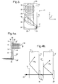
- Figure 3 shows part of a structure according to the invention. It is based on the structure shown in Figure 4 of our earlier co-pending applications GB0906266.2 and EP09275024.9 , the disclosure of which is incorporated herein by reference.
- the structure comprises a slab waveguide 10, i.e. one which has parallel principal faces 12, 14 ( Figure 4 ) and parallel opposite edge surfaces 16, 18 and 20, 22.
- the waveguide has a grating area 24 in which is provided an input transmission grating 26.
- Image bearing light is inputted to the input grating 26 generally in the Z-direction (into the plane of the Figure) and, depending on its wavelength either is diffracted to a mirrored region 27 of edge surface 18 and thence to a first pupil expansion grating 28, or is not diffracted. In the latter case it passes through the waveguide and out of the rear surface 16.
- a second slab waveguide 10' ( Figure 4a ) is disposed immediately behind the waveguide 10.
- Features corresponding to those of the waveguide 10 have the same reference numerals with the addition of a prime (').
- the input grating 26 of the first waveguide 10 is of 343nm pitch
- the input grating 26' of the second waveguide 10' is of 460nm pitch. In the example given here, all the gratings within a given waveguide will have the same pitch.
- incoming light rays 34 bearing a full colour image enter the waveguide 10 though its front principal surface 12 and are incident on the input grating 26.
- Some of the rays (those forming the image components shown in Figure 2a ) as determined by their wavelengths, the pitch of the grating, and the angle of incidence, are diffracted into the minus one reflected order (labelled -1R a in Figure 4a ) and propagate within the waveguide via the mirrored surface 27 to the first expansion grating 28 and thence to the second expansion grating 30.
- the output of the first waveguide thus is the expanded spectral portion of the full image shown in Figure 2a .
- Other rays incident on the grating 26 are not diffracted and pass straight though it as the zero transmission order labelled '0Ta' in Figure 4b .
- the grating 26 ideally should be such that any ray not diffracted into the '-1R a ' order should stay in the undiffracted '0T a ' order. Coatings applied to the profiled surface of the grating 26 can assist towards achievement of this objective as described hereafter.
- the transmitted '0Ta' light which contains the three spectral image portions shown in Figure 2b is incident on the front surface 12' of the second waveguide 10', and thence upon the input grating 26'.
- This grating has a mirrored (reflective) coating as described hereafter and thus operates wholly as a reflection grating.
- the pitch of the grating (460nm) is suitable to diffract the incident light into the '-1R b ' reflected order.
- the reflected light propagates within the waveguide via the mirrored surface 27' to the expansion grating 28' and 30', where it is expanded into the three spectral image portions of Figure 2b .
- the two waveguides 10, 10' are accurately positioned relative to each other so that expanded light 36 ( Figure 4a ) issuing from grating 30 of waveguide 10 is incident on grating 30' of waveguide 10' so as to pass through it and combine with the expanded light issuing from grating 30' to form a single full-colour image 38 as described with reference to Figure 2 .
- the choice of grating pitches determines how the colours are shared between the two waveguides.
- the first grating pitch is chosen so that it diffracts most of the blue field of view (FOV) and more than half of the green FOV.
- the pitch of the grating within the second waveguide is chosen so that it diffracts most of the red FOV and the complementary half of the green FOV.
- the system is then modelled and the grating pitches are fine-tuned to attain the highest FOV for all three colours.
- the diffraction of light into various orders is determined by the grating profile (see for example 'Diffraction Analysis of dielectric surface relief gratings' M G Moharam and T K Gaylord, Journ. Optical Soc. America, Vol 72 Issue 10, pp 1385-1392 (1982 )).
- Application of coatings to their surfaces can further tune the response of the gratings by controlling the phase of the wavefronts diffracted from the interfaces between the coating layers.
- Figure 5 shows one period of the grating 26. It can be seen that the grating has a period (pitch) of 343nm, and is of saw-tooth form with a height of 200nm. This height determines the blaze angle of the grating.
- the profiled grating surface 40 has a coating layer of silicon dioxide 42 of thickness 100nm, and a further coating layer 44 of titanium dioxide which is 40nm thick.
- Input light 34 is incident on the front surface 12 of waveguide 10 (not shown in Figure 5 ), which is of a glass having a refractive index of 1.81.
- the coating materials and thicknesses are chosen by modelling such that these multiple reflections interfere constructively and therefore the diffraction efficiency into the '-1R' order will be high.
- Other rays in this case mainly those towards the red end of the spectrum
- the grating thus effectively operates as a band pass filter.
- the grating shown in Figure 5 is required to have high diffraction efficiency for the '-1R' order, high transmission efficiency for the '0T' order, and low diffraction efficiency for all other (unwanted) orders.
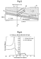
- Figure 6 shows the variation of the '+1R' (unwanted) order efficiency with the incident angle of the incoming light 34 on the front face 12 of the waveguide 10.
- the presence of the intervening parallel-sided glass material of the waveguide through which the light passes before reaching the polymer layer 39 does not affect the effective angle of incidence on the polymer layer which remains the same regardless of the refractive index of the glass.
- the efficiency of this order dotted line
- Addition of the SiO 2 layer suppresses the '+1R' efficiency, as shown by the solid line in the graph, which is desirable.
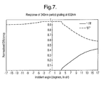
- Figure 7 shows the response of the grating 26 to monochromatic red light of wavelength 632nm; the incident angle again is that of the incoming light 34 in air on to the front face 12 of the waveguide 10. It will be noted that for angles of incidence of less than 3.5 degrees, the grating does not diffract the rays into the '-1R' order. Instead, they are transmitted through the grating in the '0Ta' mode at a transmission efficiency of 90% or more.
- Figure 8 shows the response of the grating 26 to monochromatic green light of wavelength 532nm. For angles of incidence of less than 12.5 degrees the grating does not diffract the rays into the -1R order. Zero order transmission (0Ta) in this region is approximately 90%.
- the response of the grating 26 to monochromatic blue light of wavelength 462nm is shown in Figure 9 .
- the diffraction efficiency into the -1R order is better than 50% and is better than 65% for almost all of the range.
- Figure 10 shows the reflective grating 26' of the second waveguide 10'. It is of saw-tooth form, with a period (pitch) of 460nm and a height of 200nm. It is formed on a polymer layer 39' of refractive index 1.68 and has a grating layer 46 of titanium dioxide, 70nm thick, backed by a reflective layer 48 of silver, 150nm thick, from which the incident light is reflected as shown in Figure 10 .
- GB0906266.2 and EP09275024.9 addition of the TiO 2 layer between the polymer and the silver layer yields, through the phenomenon of phase matching, high diffraction efficiency and high angular bandwidth in the '-1R' order.
- grating 26 has adequate efficiency across the whole field of view (upwards of 60% except for i > 15 degrees), and hence the inability of the grating 26' to diffract at i > 0 degrees can be tolerated.
- the invention also includes any novel feature or combination of features herein disclosed whether or not specifically claimed.
Priority Applications (5)
| Application Number | Priority Date | Filing Date | Title |
|---|---|---|---|
| EP10275047A EP2381290A1 (de) | 2010-04-23 | 2010-04-23 | Optischer Wellenleiter und Anzeigevorrichtung |
| US13/642,966 US9946068B2 (en) | 2010-04-23 | 2011-04-19 | Optical waveguide and display device |
| EP11716020.0A EP2561396B2 (de) | 2010-04-23 | 2011-04-19 | Optischer wellenleiter und anzeigevorrichtung |
| ES11716020T ES2738499T5 (es) | 2010-04-23 | 2011-04-19 | Guía de onda óptica y dispositivo de visualización |
| PCT/GB2011/050772 WO2011131978A1 (en) | 2010-04-23 | 2011-04-19 | Optical waveguide and display device |
Applications Claiming Priority (1)
| Application Number | Priority Date | Filing Date | Title |
|---|---|---|---|
| EP10275047A EP2381290A1 (de) | 2010-04-23 | 2010-04-23 | Optischer Wellenleiter und Anzeigevorrichtung |
Publications (1)
| Publication Number | Publication Date |
|---|---|
| EP2381290A1 true EP2381290A1 (de) | 2011-10-26 |
Family
ID=42315899
Family Applications (1)
| Application Number | Title | Priority Date | Filing Date |
|---|---|---|---|
| EP10275047A Ceased EP2381290A1 (de) | 2010-04-23 | 2010-04-23 | Optischer Wellenleiter und Anzeigevorrichtung |
Country Status (1)
| Country | Link |
|---|---|
| EP (1) | EP2381290A1 (de) |
Cited By (75)
| Publication number | Priority date | Publication date | Assignee | Title |
|---|---|---|---|---|
| GB2493846A (en) * | 2011-08-17 | 2013-02-20 | Bae Systems Plc | Colour projection display having two waveguides |
| WO2013188085A1 (en) * | 2012-06-12 | 2013-12-19 | Microsoft Corporation | Wide field-of-view virtual image projector |
| WO2014036537A1 (en) * | 2012-08-31 | 2014-03-06 | Nguyen Ian A | Polarization system for wavelength pass-through in a near-to-eye display |
| US8749529B2 (en) | 2012-03-01 | 2014-06-10 | Microsoft Corporation | Sensor-in-pixel display system with near infrared filter |
| US8854799B2 (en) | 2012-03-02 | 2014-10-07 | Microsoft Corporation | Flux fountain |
| US8873227B2 (en) | 2012-03-02 | 2014-10-28 | Microsoft Corporation | Flexible hinge support layer |
| WO2014210349A1 (en) * | 2013-06-28 | 2014-12-31 | Microsoft Corporation | Display efficiency optimization by color filtering |
| US9052414B2 (en) | 2012-02-07 | 2015-06-09 | Microsoft Technology Licensing, Llc | Virtual image device |
| US9075566B2 (en) | 2012-03-02 | 2015-07-07 | Microsoft Technoogy Licensing, LLC | Flexible hinge spine |
| US9152173B2 (en) | 2012-10-09 | 2015-10-06 | Microsoft Technology Licensing, Llc | Transparent display device |
| US9244280B1 (en) | 2014-03-25 | 2016-01-26 | Rockwell Collins, Inc. | Near eye display system and method for display enhancement or redundancy |
| US9244281B1 (en) | 2013-09-26 | 2016-01-26 | Rockwell Collins, Inc. | Display system and method using a detached combiner |
| US9274339B1 (en) | 2010-02-04 | 2016-03-01 | Rockwell Collins, Inc. | Worn display system and method without requiring real time tracking for boresight precision |
| US9341846B2 (en) | 2012-04-25 | 2016-05-17 | Rockwell Collins Inc. | Holographic wide angle display |
| US9354748B2 (en) | 2012-02-13 | 2016-05-31 | Microsoft Technology Licensing, Llc | Optical stylus interaction |
| US9355345B2 (en) | 2012-07-23 | 2016-05-31 | Microsoft Technology Licensing, Llc | Transparent tags with encoded data |
| US9366864B1 (en) | 2011-09-30 | 2016-06-14 | Rockwell Collins, Inc. | System for and method of displaying information without need for a combiner alignment detector |
| US9507150B1 (en) | 2011-09-30 | 2016-11-29 | Rockwell Collins, Inc. | Head up display (HUD) using a bent waveguide assembly |
| US9513748B2 (en) | 2012-12-13 | 2016-12-06 | Microsoft Technology Licensing, Llc | Combined display panel circuit |
| US9519089B1 (en) | 2014-01-30 | 2016-12-13 | Rockwell Collins, Inc. | High performance volume phase gratings |
| WO2016198832A1 (en) * | 2015-06-10 | 2016-12-15 | Wave Optics Ltd | Optical display device |
| US9523852B1 (en) | 2012-03-28 | 2016-12-20 | Rockwell Collins, Inc. | Micro collimator system and method for a head up display (HUD) |
| CN106291936A (zh) * | 2016-09-09 | 2017-01-04 | 肖鹏 | 可调节光场镜片图像显示尺寸的光学系统 |
| US9606586B2 (en) | 2012-01-23 | 2017-03-28 | Microsoft Technology Licensing, Llc | Heat transfer device |
| US9638835B2 (en) | 2013-03-05 | 2017-05-02 | Microsoft Technology Licensing, Llc | Asymmetric aberration correcting lens |
| US9674413B1 (en) | 2013-04-17 | 2017-06-06 | Rockwell Collins, Inc. | Vision system and method having improved performance and solar mitigation |
| US9715110B1 (en) | 2014-09-25 | 2017-07-25 | Rockwell Collins, Inc. | Automotive head up display (HUD) |
| US9715067B1 (en) | 2011-09-30 | 2017-07-25 | Rockwell Collins, Inc. | Ultra-compact HUD utilizing waveguide pupil expander with surface relief gratings in high refractive index materials |
| US9824808B2 (en) | 2012-08-20 | 2017-11-21 | Microsoft Technology Licensing, Llc | Switchable magnetic lock |
| US9870066B2 (en) | 2012-03-02 | 2018-01-16 | Microsoft Technology Licensing, Llc | Method of manufacturing an input device |
| US9933684B2 (en) | 2012-11-16 | 2018-04-03 | Rockwell Collins, Inc. | Transparent waveguide display providing upper and lower fields of view having a specific light output aperture configuration |
| US10031556B2 (en) | 2012-06-08 | 2018-07-24 | Microsoft Technology Licensing, Llc | User experience adaptation |
| US10088675B1 (en) | 2015-05-18 | 2018-10-02 | Rockwell Collins, Inc. | Turning light pipe for a pupil expansion system and method |
| US10108010B2 (en) | 2015-06-29 | 2018-10-23 | Rockwell Collins, Inc. | System for and method of integrating head up displays and head down displays |
| US10120420B2 (en) | 2014-03-21 | 2018-11-06 | Microsoft Technology Licensing, Llc | Lockable display and techniques enabling use of lockable displays |
| US10126552B2 (en) | 2015-05-18 | 2018-11-13 | Rockwell Collins, Inc. | Micro collimator system and method for a head up display (HUD) |
| US10156681B2 (en) | 2015-02-12 | 2018-12-18 | Digilens Inc. | Waveguide grating device |
| US10241330B2 (en) | 2014-09-19 | 2019-03-26 | Digilens, Inc. | Method and apparatus for generating input images for holographic waveguide displays |
| US10241346B2 (en) | 2016-05-07 | 2019-03-26 | Microsoft Technology Licensing, Llc | Degrees of freedom for diffraction elements in wave expander |
| US10247943B1 (en) | 2015-05-18 | 2019-04-02 | Rockwell Collins, Inc. | Head up display (HUD) using a light pipe |
| US10295824B2 (en) | 2017-01-26 | 2019-05-21 | Rockwell Collins, Inc. | Head up display with an angled light pipe |
| US10324733B2 (en) | 2014-07-30 | 2019-06-18 | Microsoft Technology Licensing, Llc | Shutdown notifications |
| US10359736B2 (en) | 2014-08-08 | 2019-07-23 | Digilens Inc. | Method for holographic mastering and replication |
| US10509241B1 (en) | 2009-09-30 | 2019-12-17 | Rockwell Collins, Inc. | Optical displays |
| US10545346B2 (en) | 2017-01-05 | 2020-01-28 | Digilens Inc. | Wearable heads up displays |
| US10598932B1 (en) | 2016-01-06 | 2020-03-24 | Rockwell Collins, Inc. | Head up display for integrating views of conformally mapped symbols and a fixed image source |
| US10642058B2 (en) | 2011-08-24 | 2020-05-05 | Digilens Inc. | Wearable data display |
| US10670876B2 (en) | 2011-08-24 | 2020-06-02 | Digilens Inc. | Waveguide laser illuminator incorporating a despeckler |
| US10678053B2 (en) | 2009-04-27 | 2020-06-09 | Digilens Inc. | Diffractive projection apparatus |
| US10690916B2 (en) | 2015-10-05 | 2020-06-23 | Digilens Inc. | Apparatus for providing waveguide displays with two-dimensional pupil expansion |
| US10725312B2 (en) | 2007-07-26 | 2020-07-28 | Digilens Inc. | Laser illumination device |
| US10732407B1 (en) | 2014-01-10 | 2020-08-04 | Rockwell Collins, Inc. | Near eye head up display system and method with fixed combiner |
| US10732569B2 (en) | 2018-01-08 | 2020-08-04 | Digilens Inc. | Systems and methods for high-throughput recording of holographic gratings in waveguide cells |
| US10747982B2 (en) | 2013-07-31 | 2020-08-18 | Digilens Inc. | Method and apparatus for contact image sensing |
| US10795160B1 (en) | 2014-09-25 | 2020-10-06 | Rockwell Collins, Inc. | Systems for and methods of using fold gratings for dual axis expansion |
| US10859768B2 (en) | 2016-03-24 | 2020-12-08 | Digilens Inc. | Method and apparatus for providing a polarization selective holographic waveguide device |
| US10890707B2 (en) | 2016-04-11 | 2021-01-12 | Digilens Inc. | Holographic waveguide apparatus for structured light projection |
| US10914950B2 (en) | 2018-01-08 | 2021-02-09 | Digilens Inc. | Waveguide architectures and related methods of manufacturing |
| US10942430B2 (en) | 2017-10-16 | 2021-03-09 | Digilens Inc. | Systems and methods for multiplying the image resolution of a pixelated display |
| US11256155B2 (en) | 2012-01-06 | 2022-02-22 | Digilens Inc. | Contact image sensor using switchable Bragg gratings |
| US11300795B1 (en) | 2009-09-30 | 2022-04-12 | Digilens Inc. | Systems for and methods of using fold gratings coordinated with output couplers for dual axis expansion |
| US11307432B2 (en) | 2014-08-08 | 2022-04-19 | Digilens Inc. | Waveguide laser illuminator incorporating a Despeckler |
| US11314084B1 (en) | 2011-09-30 | 2022-04-26 | Rockwell Collins, Inc. | Waveguide combiner system and method with less susceptibility to glare |
| US11320571B2 (en) | 2012-11-16 | 2022-05-03 | Rockwell Collins, Inc. | Transparent waveguide display providing upper and lower fields of view with uniform light extraction |
| US11366316B2 (en) | 2015-05-18 | 2022-06-21 | Rockwell Collins, Inc. | Head up display (HUD) using a light pipe |
| US11378732B2 (en) | 2019-03-12 | 2022-07-05 | DigLens Inc. | Holographic waveguide backlight and related methods of manufacturing |
| US11402801B2 (en) | 2018-07-25 | 2022-08-02 | Digilens Inc. | Systems and methods for fabricating a multilayer optical structure |
| US11442222B2 (en) | 2019-08-29 | 2022-09-13 | Digilens Inc. | Evacuated gratings and methods of manufacturing |
| US11487131B2 (en) | 2011-04-07 | 2022-11-01 | Digilens Inc. | Laser despeckler based on angular diversity |
| US11513350B2 (en) | 2016-12-02 | 2022-11-29 | Digilens Inc. | Waveguide device with uniform output illumination |
| US11543594B2 (en) | 2019-02-15 | 2023-01-03 | Digilens Inc. | Methods and apparatuses for providing a holographic waveguide display using integrated gratings |
| US11681143B2 (en) | 2019-07-29 | 2023-06-20 | Digilens Inc. | Methods and apparatus for multiplying the image resolution and field-of-view of a pixelated display |
| US11726332B2 (en) | 2009-04-27 | 2023-08-15 | Digilens Inc. | Diffractive projection apparatus |
| US11726329B2 (en) | 2015-01-12 | 2023-08-15 | Digilens Inc. | Environmentally isolated waveguide display |
| US11747568B2 (en) | 2019-06-07 | 2023-09-05 | Digilens Inc. | Waveguides incorporating transmissive and reflective gratings and related methods of manufacturing |
Citations (6)
| Publication number | Priority date | Publication date | Assignee | Title |
|---|---|---|---|---|
| GB906266A (en) | 1960-07-15 | 1962-09-19 | Phillips Petroleum Co | Process and catalyst for production of rubbery polymers |
| US6509529B2 (en) | 1998-08-19 | 2003-01-21 | Kulicke & Soffa Holdings, Inc. | Isolated flip chip of BGA to minimize interconnect stress due to thermal mismatch |
| US20050001975A1 (en) * | 2000-04-28 | 2005-01-06 | Minolta Co., Ltd. | Light separation device, blazed grating device, diffraction grating device, and illumination optical system |
| US20060221448A1 (en) * | 2005-04-04 | 2006-10-05 | Mirage Innovations Ltd. | Multi-plane optical apparatus |
| WO2007141587A1 (en) * | 2006-06-02 | 2007-12-13 | Nokia Corporation | Color distribution in exit pupil expanders |
| US7418170B2 (en) | 2004-03-29 | 2008-08-26 | Sony Corporation | Optical device and virtual image display device |
-
2010
- 2010-04-23 EP EP10275047A patent/EP2381290A1/de not_active Ceased
Patent Citations (6)
| Publication number | Priority date | Publication date | Assignee | Title |
|---|---|---|---|---|
| GB906266A (en) | 1960-07-15 | 1962-09-19 | Phillips Petroleum Co | Process and catalyst for production of rubbery polymers |
| US6509529B2 (en) | 1998-08-19 | 2003-01-21 | Kulicke & Soffa Holdings, Inc. | Isolated flip chip of BGA to minimize interconnect stress due to thermal mismatch |
| US20050001975A1 (en) * | 2000-04-28 | 2005-01-06 | Minolta Co., Ltd. | Light separation device, blazed grating device, diffraction grating device, and illumination optical system |
| US7418170B2 (en) | 2004-03-29 | 2008-08-26 | Sony Corporation | Optical device and virtual image display device |
| US20060221448A1 (en) * | 2005-04-04 | 2006-10-05 | Mirage Innovations Ltd. | Multi-plane optical apparatus |
| WO2007141587A1 (en) * | 2006-06-02 | 2007-12-13 | Nokia Corporation | Color distribution in exit pupil expanders |
Non-Patent Citations (1)
| Title |
|---|
| M G MOHARAM; T K GAYLORD: "Diffraction Analysis of dielectric surface relief gratings", JOURN. OPTICAL SOC. AMERICA, vol. 72, no. 10, 1982, pages 1385 - 1392 |
Cited By (131)
| Publication number | Priority date | Publication date | Assignee | Title |
|---|---|---|---|---|
| US10725312B2 (en) | 2007-07-26 | 2020-07-28 | Digilens Inc. | Laser illumination device |
| US10678053B2 (en) | 2009-04-27 | 2020-06-09 | Digilens Inc. | Diffractive projection apparatus |
| US11175512B2 (en) | 2009-04-27 | 2021-11-16 | Digilens Inc. | Diffractive projection apparatus |
| US11726332B2 (en) | 2009-04-27 | 2023-08-15 | Digilens Inc. | Diffractive projection apparatus |
| US10509241B1 (en) | 2009-09-30 | 2019-12-17 | Rockwell Collins, Inc. | Optical displays |
| US11300795B1 (en) | 2009-09-30 | 2022-04-12 | Digilens Inc. | Systems for and methods of using fold gratings coordinated with output couplers for dual axis expansion |
| US9274339B1 (en) | 2010-02-04 | 2016-03-01 | Rockwell Collins, Inc. | Worn display system and method without requiring real time tracking for boresight precision |
| US11487131B2 (en) | 2011-04-07 | 2022-11-01 | Digilens Inc. | Laser despeckler based on angular diversity |
| GB2493846A (en) * | 2011-08-17 | 2013-02-20 | Bae Systems Plc | Colour projection display having two waveguides |
| US9400387B2 (en) | 2011-08-17 | 2016-07-26 | Bae Systems, Plc | Projection display |
| GB2493846B (en) * | 2011-08-17 | 2016-02-10 | Bae Systems Plc | Projection Display |
| US10642058B2 (en) | 2011-08-24 | 2020-05-05 | Digilens Inc. | Wearable data display |
| US10670876B2 (en) | 2011-08-24 | 2020-06-02 | Digilens Inc. | Waveguide laser illuminator incorporating a despeckler |
| US11287666B2 (en) | 2011-08-24 | 2022-03-29 | Digilens, Inc. | Wearable data display |
| US11874477B2 (en) | 2011-08-24 | 2024-01-16 | Digilens Inc. | Wearable data display |
| US10401620B1 (en) | 2011-09-30 | 2019-09-03 | Rockwell Collins, Inc. | Waveguide combiner system and method with less susceptibility to glare |
| US11314084B1 (en) | 2011-09-30 | 2022-04-26 | Rockwell Collins, Inc. | Waveguide combiner system and method with less susceptibility to glare |
| US9977247B1 (en) | 2011-09-30 | 2018-05-22 | Rockwell Collins, Inc. | System for and method of displaying information without need for a combiner alignment detector |
| US9715067B1 (en) | 2011-09-30 | 2017-07-25 | Rockwell Collins, Inc. | Ultra-compact HUD utilizing waveguide pupil expander with surface relief gratings in high refractive index materials |
| US9366864B1 (en) | 2011-09-30 | 2016-06-14 | Rockwell Collins, Inc. | System for and method of displaying information without need for a combiner alignment detector |
| US9599813B1 (en) | 2011-09-30 | 2017-03-21 | Rockwell Collins, Inc. | Waveguide combiner system and method with less susceptibility to glare |
| US9507150B1 (en) | 2011-09-30 | 2016-11-29 | Rockwell Collins, Inc. | Head up display (HUD) using a bent waveguide assembly |
| US11256155B2 (en) | 2012-01-06 | 2022-02-22 | Digilens Inc. | Contact image sensor using switchable Bragg gratings |
| US9606586B2 (en) | 2012-01-23 | 2017-03-28 | Microsoft Technology Licensing, Llc | Heat transfer device |
| US9052414B2 (en) | 2012-02-07 | 2015-06-09 | Microsoft Technology Licensing, Llc | Virtual image device |
| US9354748B2 (en) | 2012-02-13 | 2016-05-31 | Microsoft Technology Licensing, Llc | Optical stylus interaction |
| US8749529B2 (en) | 2012-03-01 | 2014-06-10 | Microsoft Corporation | Sensor-in-pixel display system with near infrared filter |
| US9176900B2 (en) | 2012-03-02 | 2015-11-03 | Microsoft Technology Licensing, Llc | Flexible hinge and removable attachment |
| US9619071B2 (en) | 2012-03-02 | 2017-04-11 | Microsoft Technology Licensing, Llc | Computing device and an apparatus having sensors configured for measuring spatial information indicative of a position of the computing devices |
| US9852855B2 (en) | 2012-03-02 | 2017-12-26 | Microsoft Technology Licensing, Llc | Pressure sensitive key normalization |
| US9304949B2 (en) | 2012-03-02 | 2016-04-05 | Microsoft Technology Licensing, Llc | Sensing user input at display area edge |
| US9460029B2 (en) | 2012-03-02 | 2016-10-04 | Microsoft Technology Licensing, Llc | Pressure sensitive keys |
| US9465412B2 (en) | 2012-03-02 | 2016-10-11 | Microsoft Technology Licensing, Llc | Input device layers and nesting |
| US9268373B2 (en) | 2012-03-02 | 2016-02-23 | Microsoft Technology Licensing, Llc | Flexible hinge spine |
| US9904327B2 (en) | 2012-03-02 | 2018-02-27 | Microsoft Technology Licensing, Llc | Flexible hinge and removable attachment |
| US8854799B2 (en) | 2012-03-02 | 2014-10-07 | Microsoft Corporation | Flux fountain |
| US8873227B2 (en) | 2012-03-02 | 2014-10-28 | Microsoft Corporation | Flexible hinge support layer |
| US9134807B2 (en) | 2012-03-02 | 2015-09-15 | Microsoft Technology Licensing, Llc | Pressure sensitive key normalization |
| US9176901B2 (en) | 2012-03-02 | 2015-11-03 | Microsoft Technology Licensing, Llc | Flux fountain |
| US9158384B2 (en) | 2012-03-02 | 2015-10-13 | Microsoft Technology Licensing, Llc | Flexible hinge protrusion attachment |
| US10963087B2 (en) | 2012-03-02 | 2021-03-30 | Microsoft Technology Licensing, Llc | Pressure sensitive keys |
| US9618977B2 (en) | 2012-03-02 | 2017-04-11 | Microsoft Technology Licensing, Llc | Input device securing techniques |
| US9870066B2 (en) | 2012-03-02 | 2018-01-16 | Microsoft Technology Licensing, Llc | Method of manufacturing an input device |
| US8903517B2 (en) | 2012-03-02 | 2014-12-02 | Microsoft Corporation | Computer device and an apparatus having sensors configured for measuring spatial information indicative of a position of the computing devices |
| US8947864B2 (en) | 2012-03-02 | 2015-02-03 | Microsoft Corporation | Flexible hinge and removable attachment |
| US9075566B2 (en) | 2012-03-02 | 2015-07-07 | Microsoft Technoogy Licensing, LLC | Flexible hinge spine |
| US9678542B2 (en) | 2012-03-02 | 2017-06-13 | Microsoft Technology Licensing, Llc | Multiple position input device cover |
| US9766663B2 (en) | 2012-03-02 | 2017-09-19 | Microsoft Technology Licensing, Llc | Hinge for component attachment |
| US9710093B2 (en) | 2012-03-02 | 2017-07-18 | Microsoft Technology Licensing, Llc | Pressure sensitive key normalization |
| US10013030B2 (en) | 2012-03-02 | 2018-07-03 | Microsoft Technology Licensing, Llc | Multiple position input device cover |
| US9134808B2 (en) | 2012-03-02 | 2015-09-15 | Microsoft Technology Licensing, Llc | Device kickstand |
| US9523852B1 (en) | 2012-03-28 | 2016-12-20 | Rockwell Collins, Inc. | Micro collimator system and method for a head up display (HUD) |
| US11460621B2 (en) | 2012-04-25 | 2022-10-04 | Rockwell Collins, Inc. | Holographic wide angle display |
| US10690915B2 (en) | 2012-04-25 | 2020-06-23 | Rockwell Collins, Inc. | Holographic wide angle display |
| US9341846B2 (en) | 2012-04-25 | 2016-05-17 | Rockwell Collins Inc. | Holographic wide angle display |
| US10031556B2 (en) | 2012-06-08 | 2018-07-24 | Microsoft Technology Licensing, Llc | User experience adaptation |
| JP2017194693A (ja) * | 2012-06-12 | 2017-10-26 | マイクロソフト コーポレーションMicrosoft Corporation | 広視野の仮想画像プロジェクタ |
| US10107994B2 (en) | 2012-06-12 | 2018-10-23 | Microsoft Technology Licensing, Llc | Wide field-of-view virtual image projector |
| WO2013188085A1 (en) * | 2012-06-12 | 2013-12-19 | Microsoft Corporation | Wide field-of-view virtual image projector |
| CN104350411A (zh) * | 2012-06-12 | 2015-02-11 | 微软公司 | 宽视场虚拟图像投影仪 |
| US9019615B2 (en) | 2012-06-12 | 2015-04-28 | Microsoft Technology Licensing, Llc | Wide field-of-view virtual image projector |
| US9355345B2 (en) | 2012-07-23 | 2016-05-31 | Microsoft Technology Licensing, Llc | Transparent tags with encoded data |
| US9824808B2 (en) | 2012-08-20 | 2017-11-21 | Microsoft Technology Licensing, Llc | Switchable magnetic lock |
| WO2014036537A1 (en) * | 2012-08-31 | 2014-03-06 | Nguyen Ian A | Polarization system for wavelength pass-through in a near-to-eye display |
| US8885997B2 (en) | 2012-08-31 | 2014-11-11 | Microsoft Corporation | NED polarization system for wavelength pass-through |
| US9152173B2 (en) | 2012-10-09 | 2015-10-06 | Microsoft Technology Licensing, Llc | Transparent display device |
| US11320571B2 (en) | 2012-11-16 | 2022-05-03 | Rockwell Collins, Inc. | Transparent waveguide display providing upper and lower fields of view with uniform light extraction |
| US11448937B2 (en) | 2012-11-16 | 2022-09-20 | Digilens Inc. | Transparent waveguide display for tiling a display having plural optical powers using overlapping and offset FOV tiles |
| US9933684B2 (en) | 2012-11-16 | 2018-04-03 | Rockwell Collins, Inc. | Transparent waveguide display providing upper and lower fields of view having a specific light output aperture configuration |
| US9513748B2 (en) | 2012-12-13 | 2016-12-06 | Microsoft Technology Licensing, Llc | Combined display panel circuit |
| US9638835B2 (en) | 2013-03-05 | 2017-05-02 | Microsoft Technology Licensing, Llc | Asymmetric aberration correcting lens |
| US9674413B1 (en) | 2013-04-17 | 2017-06-06 | Rockwell Collins, Inc. | Vision system and method having improved performance and solar mitigation |
| US9679367B1 (en) | 2013-04-17 | 2017-06-13 | Rockwell Collins, Inc. | HUD system and method with dynamic light exclusion |
| US9664905B2 (en) | 2013-06-28 | 2017-05-30 | Microsoft Technology Licensing, Llc | Display efficiency optimization by color filtering |
| WO2014210349A1 (en) * | 2013-06-28 | 2014-12-31 | Microsoft Corporation | Display efficiency optimization by color filtering |
| US10747982B2 (en) | 2013-07-31 | 2020-08-18 | Digilens Inc. | Method and apparatus for contact image sensing |
| US9244281B1 (en) | 2013-09-26 | 2016-01-26 | Rockwell Collins, Inc. | Display system and method using a detached combiner |
| US10732407B1 (en) | 2014-01-10 | 2020-08-04 | Rockwell Collins, Inc. | Near eye head up display system and method with fixed combiner |
| US9519089B1 (en) | 2014-01-30 | 2016-12-13 | Rockwell Collins, Inc. | High performance volume phase gratings |
| US10120420B2 (en) | 2014-03-21 | 2018-11-06 | Microsoft Technology Licensing, Llc | Lockable display and techniques enabling use of lockable displays |
| US9244280B1 (en) | 2014-03-25 | 2016-01-26 | Rockwell Collins, Inc. | Near eye display system and method for display enhancement or redundancy |
| US9766465B1 (en) | 2014-03-25 | 2017-09-19 | Rockwell Collins, Inc. | Near eye display system and method for display enhancement or redundancy |
| US10324733B2 (en) | 2014-07-30 | 2019-06-18 | Microsoft Technology Licensing, Llc | Shutdown notifications |
| US11709373B2 (en) | 2014-08-08 | 2023-07-25 | Digilens Inc. | Waveguide laser illuminator incorporating a despeckler |
| US11307432B2 (en) | 2014-08-08 | 2022-04-19 | Digilens Inc. | Waveguide laser illuminator incorporating a Despeckler |
| US10359736B2 (en) | 2014-08-08 | 2019-07-23 | Digilens Inc. | Method for holographic mastering and replication |
| US10241330B2 (en) | 2014-09-19 | 2019-03-26 | Digilens, Inc. | Method and apparatus for generating input images for holographic waveguide displays |
| US11726323B2 (en) | 2014-09-19 | 2023-08-15 | Digilens Inc. | Method and apparatus for generating input images for holographic waveguide displays |
| US9715110B1 (en) | 2014-09-25 | 2017-07-25 | Rockwell Collins, Inc. | Automotive head up display (HUD) |
| US10795160B1 (en) | 2014-09-25 | 2020-10-06 | Rockwell Collins, Inc. | Systems for and methods of using fold gratings for dual axis expansion |
| US11726329B2 (en) | 2015-01-12 | 2023-08-15 | Digilens Inc. | Environmentally isolated waveguide display |
| US11740472B2 (en) | 2015-01-12 | 2023-08-29 | Digilens Inc. | Environmentally isolated waveguide display |
| US11703645B2 (en) | 2015-02-12 | 2023-07-18 | Digilens Inc. | Waveguide grating device |
| US10527797B2 (en) | 2015-02-12 | 2020-01-07 | Digilens Inc. | Waveguide grating device |
| US10156681B2 (en) | 2015-02-12 | 2018-12-18 | Digilens Inc. | Waveguide grating device |
| US10746989B2 (en) | 2015-05-18 | 2020-08-18 | Rockwell Collins, Inc. | Micro collimator system and method for a head up display (HUD) |
| US10698203B1 (en) | 2015-05-18 | 2020-06-30 | Rockwell Collins, Inc. | Turning light pipe for a pupil expansion system and method |
| US11366316B2 (en) | 2015-05-18 | 2022-06-21 | Rockwell Collins, Inc. | Head up display (HUD) using a light pipe |
| US10088675B1 (en) | 2015-05-18 | 2018-10-02 | Rockwell Collins, Inc. | Turning light pipe for a pupil expansion system and method |
| US10247943B1 (en) | 2015-05-18 | 2019-04-02 | Rockwell Collins, Inc. | Head up display (HUD) using a light pipe |
| US10126552B2 (en) | 2015-05-18 | 2018-11-13 | Rockwell Collins, Inc. | Micro collimator system and method for a head up display (HUD) |
| US10768348B2 (en) | 2015-06-10 | 2020-09-08 | Wave Optics Ltd | Optical display device |
| WO2016198832A1 (en) * | 2015-06-10 | 2016-12-15 | Wave Optics Ltd | Optical display device |
| US10108010B2 (en) | 2015-06-29 | 2018-10-23 | Rockwell Collins, Inc. | System for and method of integrating head up displays and head down displays |
| US10690916B2 (en) | 2015-10-05 | 2020-06-23 | Digilens Inc. | Apparatus for providing waveguide displays with two-dimensional pupil expansion |
| US11754842B2 (en) | 2015-10-05 | 2023-09-12 | Digilens Inc. | Apparatus for providing waveguide displays with two-dimensional pupil expansion |
| US11281013B2 (en) | 2015-10-05 | 2022-03-22 | Digilens Inc. | Apparatus for providing waveguide displays with two-dimensional pupil expansion |
| US11215834B1 (en) | 2016-01-06 | 2022-01-04 | Rockwell Collins, Inc. | Head up display for integrating views of conformally mapped symbols and a fixed image source |
| US10598932B1 (en) | 2016-01-06 | 2020-03-24 | Rockwell Collins, Inc. | Head up display for integrating views of conformally mapped symbols and a fixed image source |
| US11604314B2 (en) | 2016-03-24 | 2023-03-14 | Digilens Inc. | Method and apparatus for providing a polarization selective holographic waveguide device |
| US10859768B2 (en) | 2016-03-24 | 2020-12-08 | Digilens Inc. | Method and apparatus for providing a polarization selective holographic waveguide device |
| US10890707B2 (en) | 2016-04-11 | 2021-01-12 | Digilens Inc. | Holographic waveguide apparatus for structured light projection |
| US10241346B2 (en) | 2016-05-07 | 2019-03-26 | Microsoft Technology Licensing, Llc | Degrees of freedom for diffraction elements in wave expander |
| CN106291936A (zh) * | 2016-09-09 | 2017-01-04 | 肖鹏 | 可调节光场镜片图像显示尺寸的光学系统 |
| US11513350B2 (en) | 2016-12-02 | 2022-11-29 | Digilens Inc. | Waveguide device with uniform output illumination |
| US11586046B2 (en) | 2017-01-05 | 2023-02-21 | Digilens Inc. | Wearable heads up displays |
| US10545346B2 (en) | 2017-01-05 | 2020-01-28 | Digilens Inc. | Wearable heads up displays |
| US11194162B2 (en) | 2017-01-05 | 2021-12-07 | Digilens Inc. | Wearable heads up displays |
| US10705337B2 (en) | 2017-01-26 | 2020-07-07 | Rockwell Collins, Inc. | Head up display with an angled light pipe |
| US10295824B2 (en) | 2017-01-26 | 2019-05-21 | Rockwell Collins, Inc. | Head up display with an angled light pipe |
| US10942430B2 (en) | 2017-10-16 | 2021-03-09 | Digilens Inc. | Systems and methods for multiplying the image resolution of a pixelated display |
| US10732569B2 (en) | 2018-01-08 | 2020-08-04 | Digilens Inc. | Systems and methods for high-throughput recording of holographic gratings in waveguide cells |
| US10914950B2 (en) | 2018-01-08 | 2021-02-09 | Digilens Inc. | Waveguide architectures and related methods of manufacturing |
| US11402801B2 (en) | 2018-07-25 | 2022-08-02 | Digilens Inc. | Systems and methods for fabricating a multilayer optical structure |
| US11543594B2 (en) | 2019-02-15 | 2023-01-03 | Digilens Inc. | Methods and apparatuses for providing a holographic waveguide display using integrated gratings |
| US11378732B2 (en) | 2019-03-12 | 2022-07-05 | DigLens Inc. | Holographic waveguide backlight and related methods of manufacturing |
| US11747568B2 (en) | 2019-06-07 | 2023-09-05 | Digilens Inc. | Waveguides incorporating transmissive and reflective gratings and related methods of manufacturing |
| US11681143B2 (en) | 2019-07-29 | 2023-06-20 | Digilens Inc. | Methods and apparatus for multiplying the image resolution and field-of-view of a pixelated display |
| US11592614B2 (en) | 2019-08-29 | 2023-02-28 | Digilens Inc. | Evacuated gratings and methods of manufacturing |
| US11442222B2 (en) | 2019-08-29 | 2022-09-13 | Digilens Inc. | Evacuated gratings and methods of manufacturing |
| US11899238B2 (en) | 2019-08-29 | 2024-02-13 | Digilens Inc. | Evacuated gratings and methods of manufacturing |
Similar Documents
| Publication | Publication Date | Title |
|---|---|---|
| EP2561396B2 (de) | Optischer wellenleiter und anzeigevorrichtung | |
| EP2381290A1 (de) | Optischer Wellenleiter und Anzeigevorrichtung | |
| EP2979126B1 (de) | Verbesserungen von und in zusammenhang mit anzeigen | |
| EP2422232B1 (de) | Oberflächenreliefgitter in einem optischen wellenleiter mit einer reflektierenden oberfläche und sich an die oberfläche anpassenden dielektrischen schicht | |
| FI130178B (en) | Waveguide element and waveguide stack for display use | |
| US8934171B2 (en) | Planar optical system for wide field-of-view polychromatic imaging | |
| JP7376626B2 (ja) | ダイクロイックフィルタを使用した導波管における色分離 | |
| EP2745160B1 (de) | Projektionsanzeige | |
| GB2514658A (en) | Improvements in and relating to displays | |
| EP1748305A1 (de) | Optisches element, optisches kombinierersystem und bildanzeigeeinheit | |
| EP3414603A1 (de) | Wellenleiterbasierte displays mit antireflex- und hochreflexbeschichtung | |
| EP2784569A1 (de) | Verbesserungen von und in Zusammenhang mit Anzeigen | |
| EP3729178B1 (de) | Wellenleiter-anzeigeelement | |
| EP4176302A1 (de) | Vollfarbiger wellenleiterkombinierer mit eingebetteter metagitterung |
Legal Events
| Date | Code | Title | Description |
|---|---|---|---|
| AK | Designated contracting states |
Kind code of ref document: A1 Designated state(s): AT BE BG CH CY CZ DE DK EE ES FI FR GB GR HR HU IE IS IT LI LT LU LV MC MK MT NL NO PL PT RO SE SI SK SM TR |
|
| AX | Request for extension of the european patent |
Extension state: AL BA ME RS |
|
| PUAI | Public reference made under article 153(3) epc to a published international application that has entered the european phase |
Free format text: ORIGINAL CODE: 0009012 |
|
| STAA | Information on the status of an ep patent application or granted ep patent |
Free format text: STATUS: THE APPLICATION HAS BEEN REFUSED |
|
| 18R | Application refused |
Effective date: 20111121 |