EP2381285A2 - High density multifiber interconnect cable - Google Patents
High density multifiber interconnect cable Download PDFInfo
- Publication number
- EP2381285A2 EP2381285A2 EP11163420A EP11163420A EP2381285A2 EP 2381285 A2 EP2381285 A2 EP 2381285A2 EP 11163420 A EP11163420 A EP 11163420A EP 11163420 A EP11163420 A EP 11163420A EP 2381285 A2 EP2381285 A2 EP 2381285A2
- Authority
- EP
- European Patent Office
- Prior art keywords
- cable
- jacket
- optical fibers
- cavity
- group
- Prior art date
- Legal status (The legal status is an assumption and is not a legal conclusion. Google has not performed a legal analysis and makes no representation as to the accuracy of the status listed.)
- Withdrawn
Links
- 239000000835 fiber Substances 0.000 claims abstract description 95
- 239000013307 optical fiber Substances 0.000 claims abstract description 52
- 238000001125 extrusion Methods 0.000 claims abstract description 4
- 230000004888 barrier function Effects 0.000 claims description 14
- 229920000642 polymer Polymers 0.000 claims description 7
- 239000004760 aramid Substances 0.000 claims description 5
- 229920003235 aromatic polyamide Polymers 0.000 claims description 5
- 238000005192 partition Methods 0.000 description 9
- -1 for example Substances 0.000 description 6
- 239000000463 material Substances 0.000 description 6
- 238000004519 manufacturing process Methods 0.000 description 4
- 239000011159 matrix material Substances 0.000 description 4
- 239000004033 plastic Substances 0.000 description 4
- 229920003023 plastic Polymers 0.000 description 4
- 229920001343 polytetrafluoroethylene Polymers 0.000 description 4
- 239000004810 polytetrafluoroethylene Substances 0.000 description 4
- 239000004698 Polyethylene Substances 0.000 description 3
- 239000003086 colorant Substances 0.000 description 3
- 238000010276 construction Methods 0.000 description 3
- 238000003780 insertion Methods 0.000 description 3
- 230000037431 insertion Effects 0.000 description 3
- 238000000034 method Methods 0.000 description 3
- 229920000573 polyethylene Polymers 0.000 description 3
- 239000004709 Chlorinated polyethylene Substances 0.000 description 2
- 239000004812 Fluorinated ethylene propylene Substances 0.000 description 2
- 239000002033 PVDF binder Substances 0.000 description 2
- 239000004743 Polypropylene Substances 0.000 description 2
- 239000011230 binding agent Substances 0.000 description 2
- 229920000840 ethylene tetrafluoroethylene copolymer Polymers 0.000 description 2
- 239000011152 fibreglass Substances 0.000 description 2
- 238000009434 installation Methods 0.000 description 2
- 229920009441 perflouroethylene propylene Polymers 0.000 description 2
- 229920001155 polypropylene Polymers 0.000 description 2
- 229920002981 polyvinylidene fluoride Polymers 0.000 description 2
- RNFJDJUURJAICM-UHFFFAOYSA-N 2,2,4,4,6,6-hexaphenoxy-1,3,5-triaza-2$l^{5},4$l^{5},6$l^{5}-triphosphacyclohexa-1,3,5-triene Chemical compound N=1P(OC=2C=CC=CC=2)(OC=2C=CC=CC=2)=NP(OC=2C=CC=CC=2)(OC=2C=CC=CC=2)=NP=1(OC=1C=CC=CC=1)OC1=CC=CC=C1 RNFJDJUURJAICM-UHFFFAOYSA-N 0.000 description 1
- 229920000271 Kevlar® Polymers 0.000 description 1
- 241000220317 Rosa Species 0.000 description 1
- 230000005540 biological transmission Effects 0.000 description 1
- 239000000872 buffer Substances 0.000 description 1
- 239000004568 cement Substances 0.000 description 1
- 238000013461 design Methods 0.000 description 1
- 230000009977 dual effect Effects 0.000 description 1
- QHSJIZLJUFMIFP-UHFFFAOYSA-N ethene;1,1,2,2-tetrafluoroethene Chemical group C=C.FC(F)=C(F)F QHSJIZLJUFMIFP-UHFFFAOYSA-N 0.000 description 1
- HQQADJVZYDDRJT-UHFFFAOYSA-N ethene;prop-1-ene Chemical group C=C.CC=C HQQADJVZYDDRJT-UHFFFAOYSA-N 0.000 description 1
- 239000003063 flame retardant Substances 0.000 description 1
- 229920002313 fluoropolymer Polymers 0.000 description 1
- 239000004811 fluoropolymer Substances 0.000 description 1
- 238000012986 modification Methods 0.000 description 1
- 230000004048 modification Effects 0.000 description 1
- 229920001778 nylon Polymers 0.000 description 1
- 230000003287 optical effect Effects 0.000 description 1
- 238000012856 packing Methods 0.000 description 1
- 229920000728 polyester Polymers 0.000 description 1
- 239000002861 polymer material Substances 0.000 description 1
- 239000004800 polyvinyl chloride Substances 0.000 description 1
- 238000009877 rendering Methods 0.000 description 1
- 239000010454 slate Substances 0.000 description 1
Images


Classifications
-
- G—PHYSICS
- G02—OPTICS
- G02B—OPTICAL ELEMENTS, SYSTEMS OR APPARATUS
- G02B6/00—Light guides; Structural details of arrangements comprising light guides and other optical elements, e.g. couplings
- G02B6/44—Mechanical structures for providing tensile strength and external protection for fibres, e.g. optical transmission cables
- G02B6/4401—Optical cables
- G02B6/4407—Optical cables with internal fluted support member
-
- G—PHYSICS
- G02—OPTICS
- G02B—OPTICAL ELEMENTS, SYSTEMS OR APPARATUS
- G02B6/00—Light guides; Structural details of arrangements comprising light guides and other optical elements, e.g. couplings
- G02B6/44—Mechanical structures for providing tensile strength and external protection for fibres, e.g. optical transmission cables
- G02B6/4401—Optical cables
- G02B6/441—Optical cables built up from sub-bundles
Definitions
- the present disclosure relates to fiber optic cables and more specifically to fiber optic cables having a structure that segregates groups of optical fibers within the cable.
- MTP connectors typically connects a multi-fiber cable having twelve optical fibers.
- the current color identification scheme includes 12 distinct colors that are used to identify the fibers.
- fiber optic cables containing, for example, 24 optical fibers and 24 fiber MTP optical connectivity hardware to connect the 24 fiber cable to various devices.
- the 24 fiber cable improves efficiency as well as data transmission density and bandwidth.
- the standard 12 color code must repeat itself.
- the two groups can be distinguished by adding, for example, a stripe or some other identifying indicia to one set of fibers. Applying a dash or stripe to the fibers, however, requires operating at a low line speed, rendering the manufacturing process less efficient.
- fiber groups can be distinguished by bundling one of the fiber groups, such as by wrapping the group in a binder thread.
- the thread binder can untwist while removing the cable jacket so that the installer can no longer distinguish between the fiber groups.
- a fiber optic cable comprises an elongated jacket of continuous cross-section, a first cavity in the jacket and extending therealong, a first group of optical fibers located within the first cavity, a second cavity in the jacket and extending therealong, a second group of optical fibers located within the second cavity, and at least one strength member within and extending along the jacket, wherein the jacket is extruded such that the first and second cavities are formed during extrusion of the jacket.
- Providing separate cavities for the respective groups of fibers distinguishes the groups from each other, for example, during installation of a connector on an end of the cable. Extruding the cable jacket as a unitary piece is an efficient way to segregate the first and second fiber groups in their respective cavities.
- Each group of fibers can include twelve fibers, with each fiber in the first group having a corresponding fiber in the second group of identical color and appearance, without the requirement of additional identifying indicia.
- a fiber optic cable comprises a jacket, a cavity within the jacket extending therealong, an insert within and extending along the cavity, the insert comprising a central partition and a pair of end portions connected to the central partition, the central partition dividing the cavity into a first region and a second region, a first plurality of optical fibers grouped together in a first group in the first region, a second plurality of optical fibers grouped together in a second group in the second region, and at least one strength member within and extending along the jacket.
- the insert separates the respective groups of fibers to that they can be distinguished, for example, during installation of a connector on an end of the fiber optic cable.
- a malleable tape can be used to form first and second regions within a fiber optic cable.
- a trunk or breakout cable can be formed using a plurality of any of the cables disclosed in this specification.
- the individual cables can be wrapped or stranded around a strength member, and enclosed within an outer jacket.
- FIG. 1 is schematic cross-sectional view of a fiber optic cable according to a first embodiment.
- FIG. 2 is schematic cross-sectional view of a fiber optic cable according to a second embodiment.
- FIG. 3 is schematic cross-sectional view of a fiber optic cable according to a third embodiment.
- FIG. 4 is schematic cross-sectional view of a fiber optic cable according to a fourth embodiment.
- FIG. 5 is schematic cross-sectional view of a fiber optic cable according to a fifth embodiment.
- FIG. 6 is schematic cross-sectional view of a fiber optic cable according to a sixth embodiment.
- FIG. 7 is schematic cross-sectional view of a fiber optic cable according to a seventh embodiment.
- FIG. 8 is schematic cross-sectional view of a fiber optic cable according to an eighth embodiment.
- FIG. 9 is schematic cross-sectional view of a fiber optic cable according to an ninth embodiment.
- FIG. 10 is schematic cross-sectional view of a fiber optic cable according to a tenth embodiment.
- FIG. 11 is schematic cross-sectional view of a fiber optic trunk cable.
- the fiber optic cable constructions disclosed herein segregate at least two optical fiber groups, wherein each group contains a plurality of optical fibers.
- the plurality of optical fibers may number twelve.
- the cable constructions disclosed herein as exemplary embodiments comprise two segregated groups of twelve optical fibers of the same color and appearance.
- the cross-sections in this specification are taken on a plane perpendicular to the length of the cables.
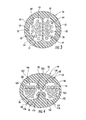
- FIG. 1 is a schematic cross-sectional view of a fiber optic cable 10 according a first embodiment.
- the fiber optic cable 10 has an elongated jacket 12 that surrounds a first cavity or first lumen 16 and a second cavity or second lumen 18 with both cavities extending along the length of the jacket 12.
- a first plurality 20 of optical fibers 21 form a first group 20 that extends along the length of the first cavity 16.
- a second plurality 22 of optical fibers 23 forms a second group 22 that extends along the length of the second cavity 18.
- the first plurality 20 of optical fibers 21 may be bundled together and the second plurality 22 of optical fibers 23 may be bundled together.
- the first plurality 20 of optical fibers 21 and the second plurality 22 of optical fibers 23 are separated from each other by a structure or barrier, which in this case is a portion of the jacket 12 extending between the cavities 16, 18.
- the cable 10 can also include one or more strength members 24 which may be arranged in one or both of the first cavity 16 and the second cavity 18 and extends the length of the respective cavities.
- the cable 10 has a generally circular cross section 14.
- the cross-section 14 may have a diameter less than or equal to about 4.0 mm, or less than or equal to 3.3 mm.
- the first cavity 16 and the second cavity 18 also have circular cross-sections 17, 19, respectively. It is not required, however, that they be circular in cross-section or that they have the same cross-sectional shape.
- the cross-sectional area of the first cavity 16 and the second cavity 18 each may be at least 1.10 millimeters squared (mm 2 ) and in some embodiments each cross-sectional area may be at least 1.25 mm 2 .
- a cavity cross-sectional area of 1.25 mm 2 provides a packing density of about 70% when twelve optical fibers are accommodated in each cavity.
- the cavities may each have a cross-sectional area of at least 0.85 mm 2 .
- the strength members 24 may be arranged toward the center of the cable 10 and each cavity 16, 18 can include one, two, or more strength members 24.
- FIGS. 2 and 3 are schematic cross-sectional views of fiber optic cable 30, 50 according to second and third embodiments, respectively.
- the cables 30, 50 have respective generally circular cross-sections 34, 54.
- the cross-sections 34, 54 may have a diameter of less than or equal to about 3.3 mm.
- the first cavities 36, 56 and the second cavities 38, 58 each have non-circular cross-sections 37, 39, and 57, 59 respectively.
- the cross-sectional area of the first cavity 36, 56 and the second cavity 38, 58 each may be at least 1.10 mm 2 and in some embodiments may be at least 1.25 mm 2 .
- the strength members 44 may be arranged toward the center of the cable 30 and each cavity 36, 38 can have one or more strength members 44.
- Four strength members 64 are shown in the exemplary cable 50 with the strength members 64 arranged at the peripheries of the cavities 56, 58.
- FIG. 4 is a schematic cross-sectional view of the fiber optic cable 90 of non-circular cross-section 94 .
- the cross-section 94 may be elliptical or oval in shape, and may have an area less than about 10 mm 2 .
- An oval or elliptical cross-section 94 may maintain cable 90 robustness while also minimizing the size and cost of the cable 90.
- the oval or elliptical cross-section 94 can be designed to provide the cable 90 with a preferential bend direction.
- the cross-section 94 may provide improved mechanical performance with regards to crush and impact since the cable 90 may be oriented in the preferential bend direction when being crushed. A crush load applied in the vertical direction in FIG.
- the aspect ratio of the elliptical cross-section 94 may range from about 1:1 to about 3.6:2.6, where aspect ratio is a ratio of the measure of a major or largest axis of the ellipse to a minor or smallest axis of the ellipse.
- An ovality for the cross-section 94 may be at least 0.8, where ovality is a ratio of the minor axis of the oval to the major axis of the oval.
- the exemplary first cavity 96 and the second cavity 98 have generally circular cross-sections 97 , 99 , respectively.
- the cross-sectional area of the first cavity 96 and the second cavity 98 each may be at least 1.10 mm 2 and in some embodiments at least 1.25 mm 2 .
- Each cavity 96 , 98 can include one or more strength members 104 that can be oriented toward the inner portion of the cavities.
- the fiber optic cable 90 can include one or more optional access features 106 formed in and extending along the periphery of the jacket 92 .
- the access features 106 are configured to facilitate opening selected portions of the jacket 92 to allow access to one or both of the fiber groups 100 , 102 .
- the access features 106 in the illustrated embodiment have the form of a partial slit or notch 107 that extends along the length of the jacket 92 .
- a pair of slits 106 can be arranged at each end of the cable 90 so that a section of the jacket 92 between the slits can be removed, allowing access to the fiber groups in either of the cavities 96 , 98 .
- the slits 106 extend a inwardly from the jacket 92 exterior.
- FIG. 5 is a schematic cross-sectional views of a fiber optic cable 110 .
- the cable 110 is substantially identical to the cable illustrated in FIG. 1 , except that the cable jacket 112 includes strength members 118 extending longitudinally through cavities 119 in the cable jacket. As illustrated in FIG. 5 , the strength members 118 are aramid yarns arranged loosely in the cavities 119.
- FIG. 6 illustrates an alternative embodiment of a cable 120 substantially identical to that of FIG. 5 , where the cable jacket 122 includes strength members 128 embedded within cavities 129. In FIG. 6 , the cable jacket 112 is extruded around the strength members 128 so that that the aramid yarns adhere to the polymer of the jacket 112. Strength members 118 , 128 as shown in FIGS. 5 and 6 can be incorporated into the jackets of any of the embodiments shown in FIGS. 1-4 .
- the first and second cavities are defined by cable jackets that are a single, continuous (or, not formed from separate pieces or materials), uniform, polymer element extruded in a one-pass process. It is to be understood, however, that coextrusion methods may allow the use of different polymer materials to form a continuous polymer jacket in a one-pass process.
- the first cavities can have the same or similar cross-sectional shapes as the second cavities, and can be arranged on each side of the cable jackets so that the cables are symmetric about a central plane. In the oval or elliptical embodiments of FIGS. 4 and 5 , the central plane can be defined along the minor axis of the ellipse.
- the central plane is a plane of symmetry dividing the cables in half and passing through the barrier between the cavities (corresponding to vertical bisection lines in the figures), so that the cavities lie on opposite sides of the central plane.
- the individual fibers in the first groups can contact the portion of the jacket defining the first cavities, and the fibers in the second groups can contact the portion of the jacket defining the second cavities.
- FIGS. 7 and 8 are schematic cross-sectional views of fiber optic cables 150, 170 according to embodiments seven and eight.
- the cables 150, 170 are of similar construction with common features, and thus will be discussed collectively.
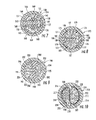
- the fiber optic cable 150, 170 has a jacket 151, 171 that surrounds a cavity 152, 172, extending along the length of the jacket 151, 171 .
- a first plurality 154, 174 of optical fibers 155, 175 form a first group 154, 174 that extends along the length of the cavity 152, 172.
- a second plurality 156, 176 of optical fibers 157, 177 forms a second group 156, 176 that extends along the length of the cavity 152, 172 .
- the first groups and the second groups can be optionally bundled.
- the first fiber group 154, 174 and the second fiber group 156, 176 are separated from each other by a structure or barrier 158, 178.
- the cable 150, 170 can include one or more strength members 160, 180, which may be arranged in the cavity 152, 172 and extending the length of the cavity.
- the barrier 158 divides the cavity 152 into two regions 162, 164 and physically separates the first fiber group 154 from the second fiber group 156.
- the barrier 158 can be an insert, such as a plastic piece into which fibers are inserted before the jacket 151 is extruded thereover.
- the insert 158 has a central partition 166 and two curved end portions 168 extending from opposite ends of the partition 166.
- the curved end portions 168 can be arcuate and can conform to an inner periphery of the jacket 151 over an arcuate distance.
- Gaps 169 are present between adjacent ends of the end portions 168. During manufacture, the gaps 169 between the end portions 168 can be widened to allow insertion of optical fibers into the insert 158 .
- Each end portion 168 can conform to at least 50 degrees of arc of the inside of the jacket 151 .
- the barrier 178 separates the first group 174 from the second group 176 and divides the cavity 172 into two regions 182, 186.
- the barrier 178 can be an insert, such as a plastic piece into which fibers are inserted before the jacket 171 is extruded thereover.
- the insert 178 has a central partition 179 and two curved end portions 187 extending from opposite ends of the partition 179.
- the curved end portions 187 can be arcuate and can conform to an inner periphery of the jacket 171 over a distance at least 50 degrees of arc.
- Gaps 189 allow insertion of optical fibers during manufacture.
- FIG. 9 is a schematic cross-sectional view of a fiber optic cable 190 having an elongated jacket 191 that surrounds a cavity 192.
- a first plurality 194 of optical fibers 195 form a first fiber group 194 that extends along the length of the cavity 192.
- a second plurality 196 of optical fibers 197 forms a second fiber group 196 that extends along the length of the cavity 192 .
- a structure or barrier 198 partitions the cavity into two regions 202, 204 and physically separates the first group of fibers 194 from the second group of fibers 196.
- the cable 190 can include one or more strength members 200 arranged in the cavity 192 and extending the length of the cavity.
- the exemplary barrier 198 is a plastic insert that bisects the cavity 192 so that a central plane of the cable 190 bisects the insert.
- the barrier 198 has opposed, inwardly curved concave walls 206 that face the groups of optical fibers 194, 196.
- FIG. 10 is a schematic cross-sectional view of a fiber optic cable 210 having an elongated jacket 211 that surrounds a cavity 212 extending along the length of the jacket 211 .
- a first plurality 214 of optical fibers 215 form a first group 214 and a second plurality 216 of optical fibers 217 forms a second group 216 that extends along the length of the cavity 212.
- One or both groups 214, 216 can be bundled.
- a barrier 218 partitions the cavity into two regions 212, 214 and physically separates the first group of fibers 214 from the second group of fibers 216.
- the cable 210 can include on or more strength members 220 extending the length of the cavity. In FIG.
- the barrier 218 has the form or a malleable tape dividing the cavity 212 into the two regions 212, 214 .
- the tape 218 can be open to allow insertion of optical fibers, and then substantially closed to allow extrusion of the jacket 211 around the tape 218 .
- Opposites sides 228, 229 of the tape 218 can be tinted different colors to identify the fibers in each region 212, 214.
- the malleable tape 218 can be a plastic material capable of deformation within the cable jacket 211.
- Malleable materials such as, for example, polytetrafluoroethylene (PTFE), and commercially available materials such as Tefion®, can be used to form the tape 218.
- a matrix material having a consistency of, for example rubber cement may be used to bundle each of the first groups and/or the second groups of optical fibers.
- the matrix material may be an ultra-violet curable matrix material.
- a colored or tinted matrix material may be used for one, or both of the groups.
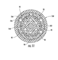
- FIG. 11 is a schematic cross-sectional view of a fiber optic trunk or breakout cable 260 having a polymer jacket 262 surrounding six cables 90 as shown in FIG. 4 .
- the trunk cable 260 may, however, comprise a plurality of any of the fiber optic cables 10, 30, 50, 110, 120, 150, 170, 190, 210.
- the trunk cable 260 also has a central strength member 264 , around which a plurality of cables may be stranded or otherwise arranged on the periphery of the strength member 264 .
- the illustrated central member 264 is a coated glass-reinforced plastic (GRP).
- the trunk cable 260 can also include additional strength members 266 for added tensile strength.
- the installer can easily distinguish between fibers 1-12 in the first fiber group of fibers from fibers 13-24 in the second fiber group, without requiring additional marking indicia for the second group of fibers. Accordingly, for each fiber in the first group, there can be a fiber in the second group of identical appearance.
- the first and second fiber groups described in this specification can each accordingly include, for example, twelve optical fibers in the 12-color sequence of blue, orange, green, brown, slate, white, red, black, yellow, purple, rose, and aqua, without either group of fibers requiring additional identifying indicia such as stripes, etc.
- a fiber optic cable according to the present embodiments can include 24 fibers of 0.25 mm outer diameter and the cable outer diameter can be approximately 3.3 mm or less. Skew performance of the optical fibers for the cable disclosed herein may be at least 3.75 Pico-seconds per meter (ps/m) to satisfy the requirement for high data rate applications.
- the strength members disclosed herein are illustrated at particular locations within a cable (i.e. the cable center, toward the cable periphery), the strength members may be disposed within a cable at any location.
- the strength members may be strands of aramid (e.g., Kevlar®) yarn or other appropriate high tensile strength materials.
- the cable jackets disclosed herein may be manufactured from any suitable material and may depend on the particular application and/or application space.
- polyvinylchloride (PVC), chlorinated polyethylene (CPE) or flame retardant polyethylene (FRPE) may be used and fluoropolymers such as polyvinylidene fluoride (PVDF), fluorinated ethylene propylene (FEP), polytetrafluoroethylene (PTFE), ethylene tetrafluoroethylene (ETFE) may be used as well.
- PVDF polyvinylidene fluoride
- FEP fluorinated ethylene propylene
- PTFE polytetrafluoroethylene
- ETFE ethylene tetrafluoroethylene
- nylons, polyesters, polyethylene (PE), or polypropylene (PP) may be used.
- Fiber optic cables having a dual cavity design may be extruded in a fashion similar to known zipcord cables; however, a round die may be necessary to fabricate the desired cross-sectional shape. Furthermore, the shape of a die tip may determine the cross-sectional shape of the cavity. The size of each cavity can be extruded so that it is sufficient to accommodate twelve colored fibers and at least two ends of aramid yarn.
Landscapes
- Physics & Mathematics (AREA)
- General Physics & Mathematics (AREA)
- Optics & Photonics (AREA)
- Insulated Conductors (AREA)
- Light Guides In General And Applications Therefor (AREA)
Abstract
Description
- The present application claims priority to
U.S. Serial No. 12/765,475 filed on April 22, 2010 - The present disclosure relates to fiber optic cables and more specifically to fiber optic cables having a structure that segregates groups of optical fibers within the cable.
- In a fiber optic network, numerous connections between fiber optic cables are required. The present standard in the art utilizes male and female industry-standard MTP connectors, which employ precision guide pins to align the internal fibers of the fiber optic cable, when connecting fiber optic cables. An MTP connector typically connects a multi-fiber cable having twelve optical fibers.
- Individual fibers in a multi-fiber cable are often distinguished from one another by color-coded jackets or buffers and an identification scheme has been developed to allow for rapid identification of the optical fibers. This is important because connecting an MTP connector correctly to a multi-fiber cable requires precise knowledge of the connection scheme of the optical fibers in the cable. The current color identification scheme includes 12 distinct colors that are used to identify the fibers.
- With the amount of data to be transmitted increasing, data centers are now using fiber optic cables containing, for example, 24 optical fibers and 24 fiber MTP optical connectivity hardware to connect the 24 fiber cable to various devices. The 24 fiber cable improves efficiency as well as data transmission density and bandwidth. For cables having more than twelve fibers, the standard 12 color code must repeat itself. Thus, in the case of a 24 fiber cable, there are two optical fibers identified with each of the colors. The two groups can be distinguished by adding, for example, a stripe or some other identifying indicia to one set of fibers. Applying a dash or stripe to the fibers, however, requires operating at a low line speed, rendering the manufacturing process less efficient.
- Alternatively, fiber groups can be distinguished by bundling one of the fiber groups, such as by wrapping the group in a binder thread. However, the thread binder can untwist while removing the cable jacket so that the installer can no longer distinguish between the fiber groups.
- In one embodiment, a fiber optic cable comprises an elongated jacket of continuous cross-section, a first cavity in the jacket and extending therealong, a first group of optical fibers located within the first cavity, a second cavity in the jacket and extending therealong, a second group of optical fibers located within the second cavity, and at least one strength member within and extending along the jacket, wherein the jacket is extruded such that the first and second cavities are formed during extrusion of the jacket. Providing separate cavities for the respective groups of fibers distinguishes the groups from each other, for example, during installation of a connector on an end of the cable. Extruding the cable jacket as a unitary piece is an efficient way to segregate the first and second fiber groups in their respective cavities. Each group of fibers can include twelve fibers, with each fiber in the first group having a corresponding fiber in the second group of identical color and appearance, without the requirement of additional identifying indicia.
- According to another embodiment, a fiber optic cable comprises a jacket, a cavity within the jacket extending therealong, an insert within and extending along the cavity, the insert comprising a central partition and a pair of end portions connected to the central partition, the central partition dividing the cavity into a first region and a second region, a first plurality of optical fibers grouped together in a first group in the first region, a second plurality of optical fibers grouped together in a second group in the second region, and at least one strength member within and extending along the jacket. The insert separates the respective groups of fibers to that they can be distinguished, for example, during installation of a connector on an end of the fiber optic cable.
- According to yet another embodiment, a malleable tape can be used to form first and second regions within a fiber optic cable.
- According to the present embodiments, a trunk or breakout cable can be formed using a plurality of any of the cables disclosed in this specification. The individual cables can be wrapped or stranded around a strength member, and enclosed within an outer jacket.
- It is to be understood that both the foregoing summary and the following detailed description are merely exemplary of preferred embodiments, and are intended to provide an overview or framework to understanding the nature and character of the claims.
- The components of the following figures are illustrated to emphasize the general principles of the present disclosure and are not necessarily drawn to scale. Reference characters designating corresponding components are repeated as necessary throughout the figures for the sake of consistency and clarity.
-
FIG. 1 is schematic cross-sectional view of a fiber optic cable according to a first embodiment. -
FIG. 2 is schematic cross-sectional view of a fiber optic cable according to a second embodiment. -
FIG. 3 is schematic cross-sectional view of a fiber optic cable according to a third embodiment. -
FIG. 4 is schematic cross-sectional view of a fiber optic cable according to a fourth embodiment. -
FIG. 5 is schematic cross-sectional view of a fiber optic cable according to a fifth embodiment. -
FIG. 6 is schematic cross-sectional view of a fiber optic cable according to a sixth embodiment. -
FIG. 7 is schematic cross-sectional view of a fiber optic cable according to a seventh embodiment. -
FIG. 8 is schematic cross-sectional view of a fiber optic cable according to an eighth embodiment. -
FIG. 9 is schematic cross-sectional view of a fiber optic cable according to an ninth embodiment. -
FIG. 10 is schematic cross-sectional view of a fiber optic cable according to a tenth embodiment. -
FIG. 11 is schematic cross-sectional view of a fiber optic trunk cable. - The fiber optic cable constructions disclosed herein segregate at least two optical fiber groups, wherein each group contains a plurality of optical fibers. The plurality of optical fibers may number twelve. Generally, the cable constructions disclosed herein as exemplary embodiments comprise two segregated groups of twelve optical fibers of the same color and appearance. The cross-sections in this specification are taken on a plane perpendicular to the length of the cables.
-
FIG. 1 is a schematic cross-sectional view of a fiberoptic cable 10 according a first embodiment. The fiberoptic cable 10 has anelongated jacket 12 that surrounds a first cavity orfirst lumen 16 and a second cavity orsecond lumen 18 with both cavities extending along the length of thejacket 12. Afirst plurality 20 ofoptical fibers 21 form afirst group 20 that extends along the length of thefirst cavity 16. Asecond plurality 22 ofoptical fibers 23 forms asecond group 22 that extends along the length of thesecond cavity 18. Thefirst plurality 20 ofoptical fibers 21 may be bundled together and thesecond plurality 22 ofoptical fibers 23 may be bundled together. Thefirst plurality 20 ofoptical fibers 21 and thesecond plurality 22 ofoptical fibers 23 are separated from each other by a structure or barrier, which in this case is a portion of thejacket 12 extending between thecavities cable 10 can also include one ormore strength members 24 which may be arranged in one or both of thefirst cavity 16 and thesecond cavity 18 and extends the length of the respective cavities. - The
cable 10 has a generallycircular cross section 14. Thecross-section 14 may have a diameter less than or equal to about 4.0 mm, or less than or equal to 3.3 mm. Thefirst cavity 16 and thesecond cavity 18 also havecircular cross-sections first cavity 16 and thesecond cavity 18 each may be at least 1.10 millimeters squared (mm2) and in some embodiments each cross-sectional area may be at least 1.25 mm2. A cavity cross-sectional area of 1.25 mm2 provides a packing density of about 70% when twelve optical fibers are accommodated in each cavity. If for example, eight fibers are provided in each cavity, the cavities may each have a cross-sectional area of at least 0.85 mm2. Generally, thestrength members 24 may be arranged toward the center of thecable 10 and eachcavity more strength members 24. -
FIGS. 2 and3 are schematic cross-sectional views of fiberoptic cable 30, 50 according to second and third embodiments, respectively. Thecables 30, 50 have respective generallycircular cross-sections first cavities second cavities non-circular cross-sections first cavity second cavity strength members 44 may be arranged toward the center of the cable 30 and eachcavity more strength members 44. Fourstrength members 64 are shown in theexemplary cable 50 with thestrength members 64 arranged at the peripheries of thecavities -
FIG. 4 is a schematic cross-sectional view of thefiber optic cable 90 ofnon-circular cross-section 94. Thecross-section 94 may be elliptical or oval in shape, and may have an area less than about 10 mm2. An oval orelliptical cross-section 94 may maintaincable 90 robustness while also minimizing the size and cost of thecable 90. The oval orelliptical cross-section 94 can be designed to provide thecable 90 with a preferential bend direction. Furthermore, thecross-section 94 may provide improved mechanical performance with regards to crush and impact since thecable 90 may be oriented in the preferential bend direction when being crushed. A crush load applied in the vertical direction inFIG. 4 , for example, may be borne along the central portion of the cable, while the optical fibers are generally disposed to the sides of the cable. The aspect ratio of theelliptical cross-section 94 may range from about 1:1 to about 3.6:2.6, where aspect ratio is a ratio of the measure of a major or largest axis of the ellipse to a minor or smallest axis of the ellipse. An ovality for thecross-section 94 may be at least 0.8, where ovality is a ratio of the minor axis of the oval to the major axis of the oval. While the terms "ellipse" and "oval" are used to describe various embodiments of this specification, the cross-sectional shapes need not necessarily follow these precise geometrical constructs, but instead may simply approximate the shape or appearance of a true "ellipse" or "oval." - The exemplary
first cavity 96 and thesecond cavity 98 have generallycircular cross-sections first cavity 96 and thesecond cavity 98 each may be at least 1.10 mm2 and in some embodiments at least 1.25 mm2. Eachcavity more strength members 104 that can be oriented toward the inner portion of the cavities. Thefiber optic cable 90 can include one or more optional access features 106 formed in and extending along the periphery of thejacket 92. The access features 106 are configured to facilitate opening selected portions of thejacket 92 to allow access to one or both of thefiber groups jacket 92. As shown inFIG. 4 , a pair ofslits 106 can be arranged at each end of thecable 90 so that a section of thejacket 92 between the slits can be removed, allowing access to the fiber groups in either of thecavities slits 106 extend a inwardly from thejacket 92 exterior. -
FIG. 5 is a schematic cross-sectional views of afiber optic cable 110. Thecable 110 is substantially identical to the cable illustrated inFIG. 1 , except that thecable jacket 112 includesstrength members 118 extending longitudinally throughcavities 119 in the cable jacket. As illustrated inFIG. 5 , thestrength members 118 are aramid yarns arranged loosely in thecavities 119.FIG. 6 illustrates an alternative embodiment of acable 120 substantially identical to that ofFIG. 5 , where thecable jacket 122 includesstrength members 128 embedded withincavities 129. InFIG. 6 , thecable jacket 112 is extruded around thestrength members 128 so that that the aramid yarns adhere to the polymer of thejacket 112.Strength members FIGS. 5 and 6 can be incorporated into the jackets of any of the embodiments shown inFIGS. 1-4 . - According to the embodiments disclosed in
FIGS. 1-6 , the first and second cavities are defined by cable jackets that are a single, continuous (or, not formed from separate pieces or materials), uniform, polymer element extruded in a one-pass process. It is to be understood, however, that coextrusion methods may allow the use of different polymer materials to form a continuous polymer jacket in a one-pass process. The first cavities can have the same or similar cross-sectional shapes as the second cavities, and can be arranged on each side of the cable jackets so that the cables are symmetric about a central plane. In the oval or elliptical embodiments ofFIGS. 4 and5 , the central plane can be defined along the minor axis of the ellipse. In the illustrated embodiments, the central plane is a plane of symmetry dividing the cables in half and passing through the barrier between the cavities (corresponding to vertical bisection lines in the figures), so that the cavities lie on opposite sides of the central plane. The individual fibers in the first groups can contact the portion of the jacket defining the first cavities, and the fibers in the second groups can contact the portion of the jacket defining the second cavities. -
FIGS. 7 and 8 are schematic cross-sectional views offiber optic cables cables fiber optic cable jacket cavity jacket first plurality 154, 174 ofoptical fibers first group 154, 174 that extends along the length of thecavity second plurality optical fibers second group cavity first fiber group 154, 174 and thesecond fiber group barrier cable more strength members cavity - Referring specifically to
FIG. 7 , thebarrier 158 divides thecavity 152 into tworegions first fiber group 154 from thesecond fiber group 156. Thebarrier 158 can be an insert, such as a plastic piece into which fibers are inserted before thejacket 151 is extruded thereover. Theinsert 158 has acentral partition 166 and twocurved end portions 168 extending from opposite ends of thepartition 166. Thecurved end portions 168 can be arcuate and can conform to an inner periphery of thejacket 151 over an arcuate distance.Gaps 169 are present between adjacent ends of theend portions 168. During manufacture, thegaps 169 between theend portions 168 can be widened to allow insertion of optical fibers into theinsert 158. Eachend portion 168 can conform to at least 50 degrees of arc of the inside of thejacket 151. - Referring specifically to
FIG. 8 , thebarrier 178 separates the first group 174 from thesecond group 176 and divides thecavity 172 into tworegions barrier 178 can be an insert, such as a plastic piece into which fibers are inserted before thejacket 171 is extruded thereover. Theinsert 178 has acentral partition 179 and twocurved end portions 187 extending from opposite ends of thepartition 179. Thecurved end portions 187 can be arcuate and can conform to an inner periphery of thejacket 171 over a distance at least 50 degrees of arc.Gaps 189 allow insertion of optical fibers during manufacture. -
FIG. 9 is a schematic cross-sectional view of afiber optic cable 190 having anelongated jacket 191 that surrounds acavity 192. A first plurality 194 ofoptical fibers 195 form a first fiber group 194 that extends along the length of thecavity 192. Asecond plurality 196 ofoptical fibers 197 forms asecond fiber group 196 that extends along the length of thecavity 192. A structure orbarrier 198 partitions the cavity into tworegions fibers 196. Thecable 190 can include one ormore strength members 200 arranged in thecavity 192 and extending the length of the cavity. Theexemplary barrier 198 is a plastic insert that bisects thecavity 192 so that a central plane of thecable 190 bisects the insert. Thebarrier 198 has opposed, inwardly curvedconcave walls 206 that face the groups ofoptical fibers 194, 196. -
FIG. 10 is a schematic cross-sectional view of afiber optic cable 210 having anelongated jacket 211 that surrounds acavity 212 extending along the length of thejacket 211. Afirst plurality 214 ofoptical fibers 215 form afirst group 214 and asecond plurality 216 ofoptical fibers 217 forms asecond group 216 that extends along the length of thecavity 212. One or bothgroups barrier 218 partitions the cavity into tworegions fibers 214 from the second group offibers 216. Thecable 210 can include on ormore strength members 220 extending the length of the cavity. InFIG. 10 , thebarrier 218 has the form or a malleable tape dividing thecavity 212 into the tworegions tape 218 can be open to allow insertion of optical fibers, and then substantially closed to allow extrusion of thejacket 211 around thetape 218. Opposites sides 228, 229 of thetape 218 can be tinted different colors to identify the fibers in eachregion malleable tape 218 can be a plastic material capable of deformation within thecable jacket 211. Malleable materials such as, for example, polytetrafluoroethylene (PTFE), and commercially available materials such as Tefion®, can be used to form thetape 218. - In the embodiments described in this specification, a matrix material having a consistency of, for example rubber cement, may be used to bundle each of the first groups and/or the second groups of optical fibers. The matrix material may be an ultra-violet curable matrix material. To distinguish between the two groups of optical fibers, a colored or tinted matrix material may be used for one, or both of the groups.
-
FIG. 11 is a schematic cross-sectional view of a fiber optic trunk orbreakout cable 260 having apolymer jacket 262 surrounding sixcables 90 as shown inFIG. 4 . Thetrunk cable 260 may, however, comprise a plurality of any of thefiber optic cables trunk cable 260 also has acentral strength member 264, around which a plurality of cables may be stranded or otherwise arranged on the periphery of thestrength member 264. The illustratedcentral member 264 is a coated glass-reinforced plastic (GRP). Thetrunk cable 260 can also includeadditional strength members 266 for added tensile strength. - According to the embodiments disclosed in this specification, during cable access and connectorization of 24f cables, for example, the installer can easily distinguish between fibers 1-12 in the first fiber group of fibers from fibers 13-24 in the second fiber group, without requiring additional marking indicia for the second group of fibers. Accordingly, for each fiber in the first group, there can be a fiber in the second group of identical appearance. The first and second fiber groups described in this specification can each accordingly include, for example, twelve optical fibers in the 12-color sequence of blue, orange, green, brown, slate, white, red, black, yellow, purple, rose, and aqua, without either group of fibers requiring additional identifying indicia such as stripes, etc. According to one embodiment, a fiber optic cable according to the present embodiments can include 24 fibers of 0.25 mm outer diameter and the cable outer diameter can be approximately 3.3 mm or less. Skew performance of the optical fibers for the cable disclosed herein may be at least 3.75 Pico-seconds per meter (ps/m) to satisfy the requirement for high data rate applications.
- Although the strength members disclosed herein are illustrated at particular locations within a cable (i.e. the cable center, toward the cable periphery), the strength members may be disposed within a cable at any location. The strength members may be strands of aramid (e.g., Kevlar®) yarn or other appropriate high tensile strength materials.
- The cable jackets disclosed herein may be manufactured from any suitable material and may depend on the particular application and/or application space. For example, polyvinylchloride (PVC), chlorinated polyethylene (CPE) or flame retardant polyethylene (FRPE) may be used and fluoropolymers such as polyvinylidene fluoride (PVDF), fluorinated ethylene propylene (FEP), polytetrafluoroethylene (PTFE), ethylene tetrafluoroethylene (ETFE) may be used as well. Depending on the burn requirements, nylons, polyesters, polyethylene (PE), or polypropylene (PP) may be used.
- Fiber optic cables having a dual cavity design (
e.g. cables - It will be apparent to those skilled in the art that various other modifications and variations can be made without departing from the spirit or scope of the present disclosure.
Claims (14)
- A fiber optic cable comprising:an elongated polymer jacket of continuous cross-section;a first cavity in the jacket and extending therealong;a first group of optical fibers located within and extending along the first cavity;a second cavity in the jacket and extending therealong, the second cavity being separate from the first cavity;a second group of optical fibers located within and extending along the second cavity; andat least one strength member within and extending along the jacket, whereinthe polymer jacket is extruded such that the first and second cavities are formed during extrusion of the polymer jacket.
- The cable of claim 1, wherein the first group of optical fibers comprises at least six optical fibers and the second group of optical fibers comprises at least six optical fibers.
- The cable of claim 1 or 2, wherein the first and second cavities each has a cross-sectional area greater than 0.85 square millimeters.
- The cable of claim 1, wherein the first group of optical fibers comprises at least twelve optical fibers and the second group of optical fibers comprises at least twelve optical fibers.
- The cable of claim 4, wherein the first and second cavities each has a cross-sectional area greater than 1.10 square millimeters.
- The cable of claim 4 or 5, wherein the first and second cavities each have a cross-sectional area greater than 1.25 square millimeters.
- The cable of any of claims 1 to 6, wherein a central plane extends between the first and the second cavity and wherein a cross-section of the jacket is symmetric about the central plane.
- The cable of claim 7, wherein the jacket includes a barrier that separates the first and second cavities, the central plane passing through the barrier.
- The cable of any of claims 1 to 8, wherein the at least one tensile strength member comprises a tensile yarn grouped with at least one of the groups of optical fibers.
- The cable of any of claims 1 to 9, further comprising at least one access feature formed in and extending along an exterior of the jacket, the access feature configured to facilitate access to at least a portion of the jacket to provide access to at least one of the groups of optical fibers.
- The cable of claim 10, wherein the at least one access feature comprises a plurality of notches or slits arranged around the exterior of the jacket.
- The cable of any of claims 1 to 11, wherein a cross-sectional width of the jacket is 4.0 millimeters or less.
- The cable of any of claims 1 to 12, wherein at least one tensile strength member comprises an aramid strand segregated from the first and second groups of optical fibers.
- The cable of any of claims 1 to 13, wherein for each optical fiber in the first group there is a corresponding optical fiber in the second group of the same color and appearance.
Applications Claiming Priority (1)
| Application Number | Priority Date | Filing Date | Title |
|---|---|---|---|
| US12/765,475 US8559778B2 (en) | 2010-04-22 | 2010-04-22 | High density multifiber interconnect cable |
Publications (2)
| Publication Number | Publication Date |
|---|---|
| EP2381285A2 true EP2381285A2 (en) | 2011-10-26 |
| EP2381285A3 EP2381285A3 (en) | 2013-07-31 |
Family
ID=44209860
Family Applications (1)
| Application Number | Title | Priority Date | Filing Date |
|---|---|---|---|
| EP11163420.0A Withdrawn EP2381285A3 (en) | 2010-04-22 | 2011-04-21 | High density multifiber interconnect cable |
Country Status (2)
| Country | Link |
|---|---|
| US (1) | US8559778B2 (en) |
| EP (1) | EP2381285A3 (en) |
Cited By (1)
| Publication number | Priority date | Publication date | Assignee | Title |
|---|---|---|---|---|
| WO2018175253A1 (en) * | 2017-03-22 | 2018-09-27 | Dow Global Technologies Llc | Optical cable with channel structure |
Families Citing this family (5)
| Publication number | Priority date | Publication date | Assignee | Title |
|---|---|---|---|---|
| EP2513695B8 (en) | 2009-12-14 | 2017-08-30 | Corning Optical Communications LLC | Multifiber subunit cable |
| US8818156B2 (en) | 2010-03-30 | 2014-08-26 | Corning Cable Systems Llc | Multiple channel optical fiber furcation tube and cable assembly using same |
| US8768127B1 (en) * | 2011-01-07 | 2014-07-01 | Superior Essex International LP | Communication cable with distinguishable fiber bundles |
| WO2015088949A1 (en) * | 2013-12-09 | 2015-06-18 | Lawrence Glaser | Enhanced ducts and duct bank systems |
| MX2021011829A (en) | 2019-03-29 | 2021-11-12 | Corning Res & Dev Corp | OPTICAL FIBER CABLE WITH PARALLEL RIBBONS SUB-UNITS. |
Citations (2)
| Publication number | Priority date | Publication date | Assignee | Title |
|---|---|---|---|---|
| WO2003060579A2 (en) * | 2002-01-18 | 2003-07-24 | Ccs Technology, Inc. | Fibre optic cable for installing in a gas conduit and a cable laying device |
| US20070098339A1 (en) * | 2002-12-19 | 2007-05-03 | Bringuier Anne G | Dry fiber optic cables and assemblies |
Family Cites Families (18)
| Publication number | Priority date | Publication date | Assignee | Title |
|---|---|---|---|---|
| GB1448793A (en) * | 1974-05-31 | 1976-09-08 | Post Office | Optical cables |
| GB1479426A (en) * | 1975-01-06 | 1977-07-13 | Bicc Ltd | Optical guides |
| US4191488A (en) | 1977-05-23 | 1980-03-04 | Harry Bickerton Limited | Securement arrangement for bicycle bearing assembly |
| GB2123978B (en) | 1982-07-12 | 1985-09-11 | Telephone Cables Ltd | Optical fibre cable |
| JPS61148012U (en) | 1985-03-04 | 1986-09-12 | ||
| WO1989007778A1 (en) | 1988-02-10 | 1989-08-24 | Fujitsu Limited | Optical fiber cable and production thereof |
| DE3922475A1 (en) | 1989-07-06 | 1991-01-17 | Siemens Ag | OPTICAL NEWS CABLE |
| CA2078928A1 (en) | 1992-09-23 | 1994-03-24 | Michael G. Rawlyk | Optical fiber units and optical cables |
| DE4421456A1 (en) | 1994-06-18 | 1995-12-21 | Kwo Kabel Gmbh | Accurate embedded of optical fibres and tensile elements in a thermoplastic |
| FR2738947B1 (en) | 1995-09-15 | 1997-10-17 | Filotex Sa | MULTI-PAIR CABLE, SHIELDED PER PAIR AND EASY TO CONNECT |
| US6074503A (en) | 1997-04-22 | 2000-06-13 | Cable Design Technologies, Inc. | Making enhanced data cable with cross-twist cabled core profile |
| DE19724919A1 (en) | 1997-06-12 | 1999-01-07 | Adolph Michael Dr | Method for generating, merging and updating data usable in a route guidance system |
| US6248954B1 (en) * | 1999-02-25 | 2001-06-19 | Cable Design Technologies, Inc. | Multi-pair data cable with configurable core filling and pair separation |
| US6297454B1 (en) | 1999-12-02 | 2001-10-02 | Belden Wire & Cable Company | Cable separator spline |
| US6477304B2 (en) * | 2000-12-22 | 2002-11-05 | Alcatel | Reinforced structure for a cable or duct with high compression resistance |
| US6826338B2 (en) | 2001-02-28 | 2004-11-30 | Asahi Glass Company, Limited | Optical fiber cable having a partitioning spacer |
| US6973246B2 (en) * | 2004-04-28 | 2005-12-06 | Furukawa Electric North America, Inc. | High count optical fiber cable |
| US7558454B2 (en) | 2006-05-22 | 2009-07-07 | Nexans | Optical fiber cable and method for making the same |
-
2010
- 2010-04-22 US US12/765,475 patent/US8559778B2/en active Active
-
2011
- 2011-04-21 EP EP11163420.0A patent/EP2381285A3/en not_active Withdrawn
Patent Citations (2)
| Publication number | Priority date | Publication date | Assignee | Title |
|---|---|---|---|---|
| WO2003060579A2 (en) * | 2002-01-18 | 2003-07-24 | Ccs Technology, Inc. | Fibre optic cable for installing in a gas conduit and a cable laying device |
| US20070098339A1 (en) * | 2002-12-19 | 2007-05-03 | Bringuier Anne G | Dry fiber optic cables and assemblies |
Cited By (1)
| Publication number | Priority date | Publication date | Assignee | Title |
|---|---|---|---|---|
| WO2018175253A1 (en) * | 2017-03-22 | 2018-09-27 | Dow Global Technologies Llc | Optical cable with channel structure |
Also Published As
| Publication number | Publication date |
|---|---|
| US8559778B2 (en) | 2013-10-15 |
| EP2381285A3 (en) | 2013-07-31 |
| US20110262088A1 (en) | 2011-10-27 |
Similar Documents
| Publication | Publication Date | Title |
|---|---|---|
| CN102782551B (en) | Multi-fiber subunit cable | |
| US8818156B2 (en) | Multiple channel optical fiber furcation tube and cable assembly using same | |
| TWI732776B (en) | Fiber optic cable | |
| US8559778B2 (en) | High density multifiber interconnect cable | |
| EP3470901B1 (en) | Optical fiber cable with dual layer buffer tube for microduct application | |
| US8290321B2 (en) | Cable with features for distinguishing between fiber groups | |
| KR20080027328A (en) | Optical fiber cable and its manufacturing method | |
| EP3338126B1 (en) | Optical fiber bundle | |
| US8768127B1 (en) | Communication cable with distinguishable fiber bundles | |
| US20200150367A1 (en) | Optical Fiber Backbone Cable Having Fire Retardant Separator | |
| EP4027180B1 (en) | Optical fiber ribbon, optical fiber cable, and connector-equipped optical fiber cord | |
| EP4030211A1 (en) | Optical fiber unit and optical fiber cable | |
| US9746629B2 (en) | Fiber-bundle assembly for maintaining a select order in an optical fiber cable | |
| CN103955041B (en) | A drop optical cable for FTTX | |
| EP3067726A1 (en) | Fiber optic distribution cables and structures therefor | |
| CN107203022A (en) | A kind of holey fiber optic cable | |
| US9195018B2 (en) | Cable with features for distinguishing between fiber groups | |
| CN111007610A (en) | Flat 8-shaped multi-core MPO optical cable and manufacturing method thereof | |
| CN210835387U (en) | Micro-beam tube type indoor optical cable for data center | |
| JP2005283765A (en) | Optical drop cable | |
| CN116626823A (en) | An easily recognizable and identifiable fiber optic cable for indoor and outdoor use |
Legal Events
| Date | Code | Title | Description |
|---|---|---|---|
| AK | Designated contracting states |
Kind code of ref document: A2 Designated state(s): AL AT BE BG CH CY CZ DE DK EE ES FI FR GB GR HR HU IE IS IT LI LT LU LV MC MK MT NL NO PL PT RO RS SE SI SK SM TR |
|
| AX | Request for extension of the european patent |
Extension state: BA ME |
|
| PUAI | Public reference made under article 153(3) epc to a published international application that has entered the european phase |
Free format text: ORIGINAL CODE: 0009012 |
|
| PUAL | Search report despatched |
Free format text: ORIGINAL CODE: 0009013 |
|
| AK | Designated contracting states |
Kind code of ref document: A3 Designated state(s): AL AT BE BG CH CY CZ DE DK EE ES FI FR GB GR HR HU IE IS IT LI LT LU LV MC MK MT NL NO PL PT RO RS SE SI SK SM TR |
|
| AX | Request for extension of the european patent |
Extension state: BA ME |
|
| RIC1 | Information provided on ipc code assigned before grant |
Ipc: G02B 6/44 20060101AFI20130626BHEP |
|
| 17P | Request for examination filed |
Effective date: 20140131 |
|
| RBV | Designated contracting states (corrected) |
Designated state(s): AL AT BE BG CH CY CZ DE DK EE ES FI FR GB GR HR HU IE IS IT LI LT LU LV MC MK MT NL NO PL PT RO RS SE SI SK SM TR |
|
| 17Q | First examination report despatched |
Effective date: 20170131 |
|
| GRAP | Despatch of communication of intention to grant a patent |
Free format text: ORIGINAL CODE: EPIDOSNIGR1 |
|
| INTG | Intention to grant announced |
Effective date: 20180126 |
|
| STAA | Information on the status of an ep patent application or granted ep patent |
Free format text: STATUS: THE APPLICATION IS DEEMED TO BE WITHDRAWN |
|
| 18D | Application deemed to be withdrawn |
Effective date: 20180606 |