EP2381140B1 - Method for controlling the shifting of an automated transmission - Google Patents
Method for controlling the shifting of an automated transmission Download PDFInfo
- Publication number
- EP2381140B1 EP2381140B1 EP20110156606 EP11156606A EP2381140B1 EP 2381140 B1 EP2381140 B1 EP 2381140B1 EP 20110156606 EP20110156606 EP 20110156606 EP 11156606 A EP11156606 A EP 11156606A EP 2381140 B1 EP2381140 B1 EP 2381140B1
- Authority
- EP
- European Patent Office
- Prior art keywords
- torque
- engine
- turbine
- clutch
- load
- Prior art date
- Legal status (The legal status is an assumption and is not a legal conclusion. Google has not performed a legal analysis and makes no representation as to the accuracy of the status listed.)
- Active
Links
Images

Classifications
-
- F—MECHANICAL ENGINEERING; LIGHTING; HEATING; WEAPONS; BLASTING
- F16—ENGINEERING ELEMENTS AND UNITS; GENERAL MEASURES FOR PRODUCING AND MAINTAINING EFFECTIVE FUNCTIONING OF MACHINES OR INSTALLATIONS; THERMAL INSULATION IN GENERAL
- F16H—GEARING
- F16H61/00—Control functions within control units of change-speed- or reversing-gearings for conveying rotary motion ; Control of exclusively fluid gearing, friction gearing, gearings with endless flexible members or other particular types of gearing
- F16H61/04—Smoothing ratio shift
- F16H61/0437—Smoothing ratio shift by using electrical signals
-
- F—MECHANICAL ENGINEERING; LIGHTING; HEATING; WEAPONS; BLASTING
- F16—ENGINEERING ELEMENTS AND UNITS; GENERAL MEASURES FOR PRODUCING AND MAINTAINING EFFECTIVE FUNCTIONING OF MACHINES OR INSTALLATIONS; THERMAL INSULATION IN GENERAL
- F16H—GEARING
- F16H61/00—Control functions within control units of change-speed- or reversing-gearings for conveying rotary motion ; Control of exclusively fluid gearing, friction gearing, gearings with endless flexible members or other particular types of gearing
- F16H61/14—Control of torque converter lock-up clutches
- F16H61/143—Control of torque converter lock-up clutches using electric control means
-
- F—MECHANICAL ENGINEERING; LIGHTING; HEATING; WEAPONS; BLASTING
- F16—ENGINEERING ELEMENTS AND UNITS; GENERAL MEASURES FOR PRODUCING AND MAINTAINING EFFECTIVE FUNCTIONING OF MACHINES OR INSTALLATIONS; THERMAL INSULATION IN GENERAL
- F16H—GEARING
- F16H63/00—Control outputs from the control unit to change-speed- or reversing-gearings for conveying rotary motion or to other devices than the final output mechanism
- F16H63/40—Control outputs from the control unit to change-speed- or reversing-gearings for conveying rotary motion or to other devices than the final output mechanism comprising signals other than signals for actuating the final output mechanisms
- F16H63/50—Signals to an engine or motor
- F16H2063/506—Signals to an engine or motor for engine torque resume after shift transition, e.g. a resume adapted to the driving style
-
- F—MECHANICAL ENGINEERING; LIGHTING; HEATING; WEAPONS; BLASTING
- F16—ENGINEERING ELEMENTS AND UNITS; GENERAL MEASURES FOR PRODUCING AND MAINTAINING EFFECTIVE FUNCTIONING OF MACHINES OR INSTALLATIONS; THERMAL INSULATION IN GENERAL
- F16H—GEARING
- F16H2306/00—Shifting
- F16H2306/40—Shifting activities
- F16H2306/52—Applying torque to new gears
-
- F—MECHANICAL ENGINEERING; LIGHTING; HEATING; WEAPONS; BLASTING
- F16—ENGINEERING ELEMENTS AND UNITS; GENERAL MEASURES FOR PRODUCING AND MAINTAINING EFFECTIVE FUNCTIONING OF MACHINES OR INSTALLATIONS; THERMAL INSULATION IN GENERAL
- F16H—GEARING
- F16H45/00—Combinations of fluid gearings for conveying rotary motion with couplings or clutches
- F16H45/02—Combinations of fluid gearings for conveying rotary motion with couplings or clutches with mechanical clutches for bridging a fluid gearing of the hydrokinetic type
Definitions
- the invention relates to a method for switching control of an automated manual transmission according to the preamble of patent claim 1, as described in the DE 100 45 337A1 ,
- a transmission type known per se in which circuits, in contrast to so-called powershift transmissions, such as planetary automatic transmissions and dual-clutch transmissions, are connected to a pull or thrust interruption.
- Such transmissions are mostly of the countershaft type and have a single input shaft which is usually connected via an automated friction clutch, such as an automatic transmission clutch.
- an automated friction clutch such as an automatic transmission clutch.
- a passively closable single or multi-disc dry clutch or an actively closable multi-plate clutch with the drive shaft of the drive motor can be connected or separated from this.
- Such a friction clutch serves both as a starting element and as a clutch.
- the friction clutch bridges during startup operations in the slip operation, the speed difference between the drive shaft of the drive motor and the input shaft of the gearbox. The same applies to maneuvering, crawling and driving at low speed, if there is no correspondingly high translated creeper available.
- the friction clutch at the beginning of a Switching fully open to allow the load-free interpretation of the loaded load gear and the load-free synchronization and insertion of the target gear, and subsequently completely closed again.
- the publications DE 10 2004 059 733 A1 and DE 10 2004 059 744 A1 disclose a gear unit with a starting element in the form of a hydrodynamic component, with a device associated with the starting element for bridging the starting element and with a change gear comprising at least one gear ratio forming speed / torque converter.
- the bypass device comprises a bypass circuit for selectively transmitting power via two power branches - a first hydrodynamic power branch and a second mechanical power branch between the transmission input and the input of the gearbox.
- the lockup circuit includes two speed / torque converters.
- At least one of the speed / torque conversion means of the lock-up circuit and / or at least one element of the speed-forming Drehiere- / Drehmomentwandlungseiniichtitch in different power transmission branches between the transmission input and transmission output can be integrated or switched.
- the transmission unit according to the DE 10 2004 059 744 A1 discloses means for selectively interrupting or ensuring power transmission across the individual power branches.
- the means comprise for selectively interrupting or guaranteeing the power transmission across the individual power branches a arranged in the hydrodynamic power branch between the secondary and change gear freewheel.
- planetary automatic transmissions are often used in conjunction with an upstream hydrodynamic torque converter, such as an engine.
- Ecomat® ZF Friedrichshafen AG is used for particularly heavy commercial vehicles, such as. Crane and heavy duty tractors, including the combinations of an automated manual transmission provided with an upstream torque converter clutch, such as e.g. on the TC-Tronic® transmission of ZF Friedrichshafen AG.
- a torque converter clutch is a hydrodynamic torque converter provided with a lock-up clutch and a separating clutch downstream thereof, in which the torque converter with open lock-up clutch and closed disconnect clutch as a starting element and the disconnect clutch with closed lockup clutch serve as a clutch. If a wear-free retarder is required, the arrangement of a separate retarder is required in the case of the abovementioned drive trains, which is less advantageous with increased space requirement and weight of the drive train.
- VAB wear-free integrated start-up and braking element
- hydrodynamic starting and braking element is a type of hydrodynamic starting element known with integrated retarder, which can be commonly referred to as hydrodynamic starting and braking element.
- This is a hydrodynamic coupling provided with a lockup clutch, whose turbine wheel can be connected via an overrunning clutch to an intermediate shaft connected to the input shaft of a downstream gearbox and can be braked against a housing via a turbine brake.
- the hydrodynamic coupling is used with open lock-up clutch and open turbine brake as starting element, and with closed lock-up clutch and closed turbine brake and consequently braked and decoupled over the unlocked one-way clutch from the intermediate shaft turbine as a retarder.
- the drive or braking torque transmitted between the impeller and the turbine wheel is controllable via the degree of filling, ie the amount of fluid contained in the torus space receiving the impeller and the turbine wheel.
- a hydrodynamic torque converter is used instead of the hydrodynamic coupling.
- this known starting and braking element of the torque converter is used with open lock-up clutch and open turbine brake as a starting element, and with closed lock-up clutch and closed turbine brake as a retarder.
- the torque transmitted between the impeller and the turbine wheel can be regulated via the degree of filling and possibly also via an adjustment of the blades of the deflecting wheel arranged between the impeller and the turbine wheel.
- the hydrodynamic torque converter Compared to a hydrodynamic coupling, the hydrodynamic torque converter has a high speed difference between the impeller and the turbine wheel, ie in particular when the vehicle is stationary, a torque increase of up to 2.5, whereby even with a weaker drive motor, a relatively high Anfahrsteilmix and starting acceleration is available.
- the drive motors are usually designed as turbocharged diesel engines, which have a special load-bearing characteristic.
- a turbocharged internal combustion engine under load may spontaneously, i. With high torque gradient, only reach a below the full load torque lying suction torque. A further increase of the engine torque is possible, albeit with a smaller torque gradient, in the short term only above the charging limit speed, from which the turbocharger causes a significant increase in the boost pressure and thus the engine torque.
- turbo lag fürzugschw kaue recorded Due to the limitation of the spontaneously achievable under load engine torque to the suction torque turbo charged supercharged engines below the supercharging speed thus a significant, generally referred to as turbo lag fürzugschwhnee recorded, which is particularly noticeable when given by the deflection of the accelerator pedal power demand of the driver corresponds to the suction torque lying engine torque.
- the present invention is therefore based on the object to propose a method for switching control of an automated manual transmission with an upstream hydrodynamic starting and braking element of the type mentioned, with the train at a train, defined as upshift or train downshifting the occurrence of a draft weakness of the drive motor during load build-up on End of the train circuit can be avoided.
- the invention is based on a motor vehicle, in particular a commercial vehicle, whose drive train has a drive motor designed as a turbocharged internal combustion engine and an automated gearbox whose input shaft is connected to the drive shaft of the drive motor via a special starting element.
- the starting element is embodied as a hydrodynamic starting and braking element provided with a pump wheel and a turbine wheel whose pump wheel can be connected directly to an intermediate shaft connected to the input shaft via a lockup clutch, and whose turbine wheel can be connected via an overrunning clutch to the intermediate shaft and via a turbine brake a housing can be braked.
- the base of the hydrodynamic starting and braking element can be formed both by a hydrodynamic coupling and by a hydrodynamic torque converter.
- the input shaft of the gearbox is held largely free of torque by taking place at the beginning of the circuit load reduction, so that the loaded load gear designed largely load-free and the target gear to be engaged largely synchronized and loaded load.
- the load is reduced when the turbine brake and lock-up clutch closed by reducing the engine torque generated by the drive motor and the opening of the lock-up clutch, which, however, may occur in a train circuit during load build-up at the end of the circuit sequence known as turbo lag draft weakness of the drive motor.
- the load is reduced by the method according to the invention while maintaining the output from the drive motor motor torque M M by building a correspondingly high resistance torque in the hydrodynamic starting and braking element.
- the turbine brake is at least partially closed at the beginning of the train circuit and the transmitted from the hydrodynamic starting and braking element on the turbine brake torque M TB is set to the engine torque M M of the drive motor, defined by
- M TB
- the turbine brake If the turbine brake is kept completely closed during the switching operation and thus the turbine wheel is fixed to the housing, the work performed by the drive motor is absorbed by the fluid located in the torus space of the hydrodynamic starting and braking element, which then has to be sufficiently cooled.
- the turbine brake when the turbine brake is only partially closed during the shift operation and consequently is in slipping operation, the work done by the drive motor is largely absorbed by the turbine brake and only to a small extent by the fluid in the toroidal space of the hydrodynamic starting and braking element , In this case the turbine brake must be designed wear-resistant and effectively cooled.
- the lock-up clutch can be selectively opened or at least partially kept closed, since the torque of the drive motor is compensated by the braking torque set on the turbine brake and in the hydrodynamic starting and braking element.
- a train downshift can be provided that the lock-up clutch remains at least partially closed, and that the synchronization of the target gear is done by increasing the engine speed of the drive motor.
- the input shaft is directly coupled to the drive shaft of the drive motor, so that the time required to synchronize the target gear acceleration of the input shaft is advantageously generated via the taking place in the speed adjustment of the drive motor increasing the engine speed.
- This procedure is particularly useful in an unsynchronized design of the gearbox, but also advantageous in a synchronized design of the gearbox, since an acceleration of the input shaft on the Reibsynchronmaschine the target gear mostly a different speed curve gives as the caused by the speed adjustment of the drive motor speed curve.
- the friction synchronization of the target gear would therefore work in part against the engine torque and moment of inertia of the drive motor and the turbine wheel, which would lead to increased wear and unnecessary synchronization delay.
- the lock-up clutch remains at least partially closed, and that the synchronization of the target gear is done by reducing the engine speed of the drive motor. Due to the reduction of the engine speed, the input shaft of the gearbox is decoupled by the unlocked one-way clutch of the turbine of the hydrodynamic starting and switching element, but coupled via the at least partially closed lock-up clutch to the drive shaft of the drive motor.
- the required for synchronization of the target gear delay of the input shaft is therefore also expediently generated via the taking place in the speed adjustment of the drive motor reduction of the engine speed. This applies equally to unsynchronized as well as synchronized manual transmissions.
- a train downshift can also be provided that the lock-up clutch is fully opened, and that the synchronization of the target gear with fully closed turbine brake by an internal gear synchronizer or by increasing the engine speed of the drive motor in conjunction with a partial closing of the lock-up clutch.
- the one-way clutch is unlocked and the turbine wheel is thus decoupled from the input shaft of the manual transmission.
- the acceleration of the input shaft which is necessary for the synchronization of the target gear, can therefore optionally be achieved via the friction synchronization in the case of a synchronized gearbox the target gear or by taking place in the context of the speed adjustment of the drive motor increase in the engine speed in conjunction with a partial closing of the lock-up clutch.
- the synchronization of the target gear can only be done by increasing the engine speed of the drive motor.
- the lockup clutch is fully opened, and that the synchronization of the target gear in the case of a partially closed turbine brake is achieved by an increase in the engine speed of the drive motor.
- the turbine wheel is also accelerated and this is thereby coupled by the blocking of the overrunning clutch to the input shaft of the gearbox.
- the acceleration of the input shaft by the drive motor is thus in this case via the hydrodynamic starting and braking element.
- Analogous to the procedure described above for a train downshift may be provided in a Switzerlandrochscnies that the lock-up clutch is fully opened, and that the synchronization of the target gear with fully closed turbine brake and thus decoupled from the input shaft turbine by an internal gear synchronizer, i. by the friction synchronization of the target gear or by a transmission brake, or by reducing the engine speed of the drive motor in conjunction with a partial closing of the lock-up clutch.
- a traction upshift also be provided that the lock-up clutch is fully opened, and that the synchronization of the target gear at partially closed turbine brake by an internal gear synchronizer, ie by the Reibsynchronmaschine the target gear or by a transmission brake, guided by the input shaft speed n GE above the turbine speed n T , defined by n GE > n T , or by reducing the engine speed of the drive motor in conjunction with a partial closing of the lock-up clutch.
- an internal gear synchronizer ie by the Reibsynchronmaschine the target gear or by a transmission brake
- the increase in the engine speed can in each case by a brief increase in the engine torque M M of the drive motor and / or by a short-term reduction of the hydrodynamic starting and braking element, ie the hydrodynamic coupling or the hydrodynamic torque converter, transmitted torque M TB and / or be effected by a brief opening or further opening of the turbine brake.
- the reduction of the engine speed can be achieved in each case by a brief reduction in the engine torque M M of the drive motor and / or by a brief increase in the torque M TB transmitted by the hydrodynamic starting and braking element, ie the hydrodynamic clutch or the hydrodynamic torque converter, and partially closed Turbine brake additionally be effected by a brief further closing of the turbine brake.
- the present invention is based on an automated manual transmission with an input shaft 3, which is connected via a hydrodynamic starting and braking element 2, 2 'to the drive shaft 1 of a drive motor designed as a turbocharged internal combustion engine.
- the hydrodynamic starting and braking element 2 is based on a hydrodynamic coupling 4, which has a pump wheel 5 and a turbine wheel 6.
- the impeller 5 is rotatably connected via an input element 7 with the drive shaft 1 of the drive motor, not shown.
- the input element 7 and thus both the drive shaft 1 of the drive motor and the impeller 5 are connected via a lock-up clutch 8 with an intermediate shaft 9 which is coupled to a torsional vibration damper 10 and rotatably connected to the input shaft 3 of the gearbox, not shown.
- the turbine wheel 6 is rotatably connected via an overrunning clutch 11 with the intermediate shaft 9 and thus with the input shaft 3.
- the one-way clutch 11 locks at a torque transmission from the turbine wheel 6 in the intermediate shaft 9 and unlocked at faster rotating intermediate shaft 9.
- the turbine 6 via a turbine brake 12 relative to a housing 13 can be braked and locked.
- the hydrodynamic starting and braking element 2 ' is based on a hydrodynamic torque converter 14 which has an impeller 15, a turbine wheel 16 and a deflecting wheel 17 arranged between the impeller 15 and the turbine wheel 16.
- the impeller 15 is connected via an input element 7 'rotatably connected to the drive shaft 1 of the drive motor, not shown.
- the input element 7 'and thus both the drive shaft 1 of the drive motor and the impeller 15 are connected via a lock-up clutch 8' with an intermediate shaft 9 'coupled to a torsional vibration damper 10' and rotatably connected to the input shaft 3 of the shift transmission, not shown ,
- the turbine wheel 16 is connected via an overrunning clutch 11 'rotatably connected to the intermediate shaft 9' and thus connectable to the input shaft.
- the overrunning clutch 11 ' locks in a torque transmission from the turbine wheel 16 in the intermediate shaft 9' and unlocked at faster rotating intermediate shaft 9 '.
- the turbine wheel 16 via a turbine brake 12 'with respect to a housing 13' can be braked and locked.
- the deflection wheel 17 can also be locked via an overrunning clutch 18 with respect to the housing 13 '.
- the one-way clutch 18 locks at a rotation of the guide wheel 17 against the direction of rotation of the drive shaft 1 and unlocks upon rotation of the guide wheel 17 in the direction of rotation of the drive shaft.
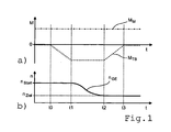
- FIG. 1 the process sequence according to the invention of a circuit-related load reduction and load build-up is exemplified for a pull upshift.
- Fig. 1 a shows the time courses of the engine torque M M delivered by the drive engine and the braking torque M TB received by the hydrodynamic clutch 4 or the hydrodynamic torque converter 14 and recorded by the turbine brake 12, 12 ', while in FIG Fig. 1b the time course of the input shaft speed n GE of the gearbox is shown.
- the input shaft 3 of the gearbox between the times t1 and t2 by an internal gear synchronizer or by the drive motor from the starting speed n start at the beginning of the upshift to the target speed n target for engaging the target gear is braked.
- the subsequent load build-up takes place in that the turbine brake 12, 12 'is completely opened again up to the time t3.
- the full engine torque M M is applied to the input shaft 3 of the gearbox again from the time t3.
- a collapse of the spontaneously deliverable by the drive motor under load engine torque M M which can occur in a turbocharged internal combustion engine after a reduction of the output engine torque M M performed during load build-up, is reliably prevented according to the method according to the invention.
Abstract
Description
Die Erfindung betrifft ein Verfahren zur Schaltsteuerung eines automatisierten Schaltgetriebes gemäß dem Oberbegriff des Patentanspruchs 1, wie beschrieben in der
In Kraftfahrzeugen kommen immer häufiger automatisierte Schaltgetriebe zur Anwendung, bei denen die Gangwahl, die Auslösung von Schaltvorgängen und das Ein- und Auslegen der Gänge automatisiert, d.h. durch die Auswertung von Betriebsparametern in einem Getriebesteuergerät und die Ansteuerung zugeordneter Stellantriebe, erfolgen. Häufig besteht bei derartigen Schaltgetrieben zudem die Möglichkeit, dass der Fahrer Schaltungen auch manuell auslösen kann, wobei diese üblicherweise auf ihre Zulässigkeit überprüft und nur bei Einhaltung vorgegebener Betriebsgrenzen, wie z.B. vorgegebenen Mindest- und Höchstdrehzahlen des Antriebsmotors, ausgeführt werden.In motor vehicles, automated manual transmissions are increasingly being used in which the gear selection, the triggering of gear shifts and the engagement and disengagement of gears are automated, i. by the evaluation of operating parameters in a transmission control unit and the control of associated actuators done. Frequently, in such transmissions, there is also the possibility that the driver can also trigger circuits manually, which usually checks for their permissibility and only if predetermined operating limits, such as, for example, are met. predetermined minimum and maximum speeds of the drive motor to be executed.
Vorliegend wird von einer an sich bekannten Getriebebauart ausgegangen, bei der Schaltungen im Unterschied zu so genannten Lastschaltgetrieben, wie Planeten-Automatgetrieben und Doppelkupplungsgetrieben, mit einer Zug- bzw. Schubkraftunterbrechung verbunden sind. Derartige Schaltgetriebe sind zumeist in Vorgelegebauweise ausgeführt und weisen eine einzige Eingangswelle auf, die üblicherweise über eine automatisierte Reibungskupplung, wie z.B. eine passiv schließbare Ein- oder Mehrscheiben-Trockenkupplung oder eine aktiv schließbare Lamellenkupplung, mit der Triebwelle des Antriebsmotors verbindbar bzw. von dieser trennbar ist.In the present case, it is assumed that a transmission type known per se is used, in which circuits, in contrast to so-called powershift transmissions, such as planetary automatic transmissions and dual-clutch transmissions, are connected to a pull or thrust interruption. Such transmissions are mostly of the countershaft type and have a single input shaft which is usually connected via an automated friction clutch, such as an automatic transmission clutch. a passively closable single or multi-disc dry clutch or an actively closable multi-plate clutch, with the drive shaft of the drive motor can be connected or separated from this.
Eine derartige Reibungskupplung dient sowohl als Anfahrelement als auch als Schaltkupplung. Als Anfahrelement überbrückt die Reibungskupplung bei Anfahrvorgängen im Schlupfbetrieb die Drehzahldifferenz zwischen der Triebwelle des Antriebsmotors und der Eingangswelle des Schaltgetriebes. Dasselbe gilt für ein Rangieren, Kriechen und Fahren mit niedriger Geschwindigkeit, wenn hierzu kein entsprechend hoch übersetzter Kriechgang zur Verfügung steht. Als Schaltkupplung wird die Reibungskupplung zu Beginn eines Schaltvorgangs vollständig geöffnet, um das lastfreie Auslegen des eingelegten Lastgangs und das lastfreie Synchronisieren und Einlegen des Zielgangs zu ermöglichen, und nachfolgend wieder vollständig geschlossen.Such a friction clutch serves both as a starting element and as a clutch. As a starting element, the friction clutch bridges during startup operations in the slip operation, the speed difference between the drive shaft of the drive motor and the input shaft of the gearbox. The same applies to maneuvering, crawling and driving at low speed, if there is no correspondingly high translated creeper available. As a clutch, the friction clutch at the beginning of a Switching fully open to allow the load-free interpretation of the loaded load gear and the load-free synchronization and insertion of the target gear, and subsequently completely closed again.
Da der mechanische Verschleiß und die thermische Belastung einer Reibungskupplung im Schlupfbetrieb mit zunehmender Fahrzeugmässe und bei erhöhter Zuglast des Antriebsmotors stark ansteigen, stehen für schwere Nutzfahrzeuge verschiedene Bauarten hydrodynamischer Anfahrelemente zur Verfügung, die ein weitgehend verschleißfreies Anfahren und Rangieren ermöglichen.Since the mechanical wear and the thermal load of a friction clutch in slipping operation with increasing vehicle dimensions and increased tensile load of the drive motor increase sharply, different types of hydrodynamic starting elements are available for heavy commercial vehicles that allow a largely wear-free starting and maneuvering.
Die Offenlegungsschriften
Während bei Stadtbussen häufig Planeten-Automatgetriebe in Verbindung mit einem vorgeschalteten hydrodynamischen Drehmomentwandler, wie z.B. der Ecomat® der ZF Friedrichshafen AG, zum Einsatz kommen, ist für besonders schwere Nutzfahrzeuge, wie z.B. Kranfahrzeuge und Schwerlastzugmaschinen, unter anderem die Kombinationen eines automatisierten Schaltgetriebes mit einer vorgeschalteten Wandlerschaltkupplung vorgesehen, wie z.B. beim TC-Tronic®-Getriebe der ZF Friedrichshafen AG.For city buses, planetary automatic transmissions are often used in conjunction with an upstream hydrodynamic torque converter, such as an engine. Ecomat® ZF Friedrichshafen AG, is used for particularly heavy commercial vehicles, such as. Crane and heavy duty tractors, including the combinations of an automated manual transmission provided with an upstream torque converter clutch, such as e.g. on the TC-Tronic® transmission of ZF Friedrichshafen AG.
Bei einer Wandlerschaltkupplung handelt es sich um einen mit einer Überbrückungskupplung versehenen hydrodynamischen Drehmomentwandler und eine diesem antriebstechnisch nachgeordnete Trennkupplung, bei welcher der Drehmomentwandler bei geöffneter Überbrückungskupplung und geschlossener Trennkupplung als Anfahrelement und die Trennkupplung bei geschlossener Überbrückungskupplüng als Schaltkupplung dienen. Bei Bedarf einer verschleißfreien Dauerbremse ist bei den vorgenannten Antriebssträngen die Anordnung eines separaten Retarders erForderlich, was weniger vorteilhaft mit einem erhöhten Bauraumbedarf und Gewicht des Antriebsstrangs verbunden ist.In a torque converter clutch is a hydrodynamic torque converter provided with a lock-up clutch and a separating clutch downstream thereof, in which the torque converter with open lock-up clutch and closed disconnect clutch as a starting element and the disconnect clutch with closed lockup clutch serve as a clutch. If a wear-free retarder is required, the arrangement of a separate retarder is required in the case of the abovementioned drive trains, which is less advantageous with increased space requirement and weight of the drive train.
Dagegen ist mit dem "VIAB" (Verschleißfreies Integriertes Anfahr- und Bremselement) der Voith Turbo AG eine Bauart eines hydrodynamischen Anfahrelementes mit integriertem Retarder bekannt, das allgemein als hydrodynamisches Anfahr- und Bremselement bezeichnet werden kann. Es handelt sich dabei um eine mit einer Überbrückungskupplung versehene hydrodynamische Kupplung, deren Turbinenrad über eine Freilaufkupplung mit einer mit der Eingangswelle eines nachgeschalteten Schaltgetriebes verbundenen Zwischenwelle verbindbar und über eine Turbinenbremse gegenüber einem Gehäuse abbremsbar ist.By contrast, Voith Turbo AG's "VIAB" (wear-free integrated start-up and braking element) is a type of hydrodynamic starting element known with integrated retarder, which can be commonly referred to as hydrodynamic starting and braking element. This is a hydrodynamic coupling provided with a lockup clutch, whose turbine wheel can be connected via an overrunning clutch to an intermediate shaft connected to the input shaft of a downstream gearbox and can be braked against a housing via a turbine brake.
Bei diesem Anfahr- und Bremselement, dessen schematischer Aufbau z.B. in der
Bei einem dem vorgenannten "VIAB" ähnlichen hydrodynamischen Anfahr- und Bremselement, das in der
Insbesondere bei Nutzfahrzeugen sind die Antriebsmotoren üblicherweise als turboaufgeladene Dieselmotoren ausgebildet, die eine spezielle Lastaufbaucharakteristik aufweisen. So kann ein turboaufgeladener Verbrennungsmotor unter Last spontan, d.h. mit hohem Drehmomentgradienten, nur ein unterhalb des Volllastmomentes liegendes Saugmoment erreichen. Eine weitere Erhöhung des Motormomentes ist, wenn auch mit geringerem Drehmomentgradienten, kurzfristig nur oberhalb der Ladegrenzdrehzahl möglich, ab welcher der Turbolader eine deutliche Erhöhung des Ladedrucks und damit des Motormomentes bewirkt. Aufgrund der Begrenzung des unter Last spontan erreichbaren Motormomentes auf das Saugmoment ist bei turboaufgeladenen Verbrennungsmotoren unterhalb der Ladegrenzdrehzahl somit eine deutliche, allgemein als Turboloch bezeichnete Durchzugsschwäche zu verzeichnen, die sich besonders dann bemerkbar macht, wenn die durch die Auslenkung des Fahrpedals gegebene Leistungsanforderung des Fahrers einem über dem Saugmoment liegenden Motormoment entspricht.In particular, in commercial vehicles, the drive motors are usually designed as turbocharged diesel engines, which have a special load-bearing characteristic. Thus, a turbocharged internal combustion engine under load may spontaneously, i. With high torque gradient, only reach a below the full load torque lying suction torque. A further increase of the engine torque is possible, albeit with a smaller torque gradient, in the short term only above the charging limit speed, from which the turbocharger causes a significant increase in the boost pressure and thus the engine torque. Due to the limitation of the spontaneously achievable under load engine torque to the suction torque turbo charged supercharged engines below the supercharging speed thus a significant, generally referred to as turbo lag Durchzugschwäche recorded, which is particularly noticeable when given by the deflection of the accelerator pedal power demand of the driver corresponds to the suction torque lying engine torque.
Zur Vermeidung oder zumindest Abschwächung des unerwünschten Turbolochs sind zwar mehrere Lösungen bekannt geworden, wie z.B. eine verstellbare Turbinenschaufelgeometrie zur Verbesserung des Ansprechverhaltens des Abgasturboladers, oder Zusatzeinrichtungen zur Erhöhung des Ladedruckes bei niedriger Motordrehzahl, wie ein mechanisch antreibbarer Kompressor, ein elektrisch antreibbarer Zusatzverdichter, oder ein mechanischer oder elektrischer Antrieb der Triebwelle des Abgasturboladers. Derartige Einrichtungen sind jedoch relativ aufwendig und teuer, erhöhen den Bauraumbedarf und stellen ein erhöhtes Störungspotential für den Betrieb des Verbrennungsmotors dar, so dass häufig darauf verzichtet wird.To avoid or at least mitigate the unwanted turbo lag several solutions have become known, such as an adjustable turbine blade geometry to improve the response of the exhaust gas turbocharger, or additional devices to increase the boost pressure at low engine speed, such as a mechanically driven compressor, an electrically driven auxiliary compressor, or a mechanical or electrical drive of the drive shaft of the exhaust gas turbocharger. However, such devices are relatively complicated and expensive, increase the space requirement and represent an increased potential for interference for the operation of the internal combustion engine, so that is often dispensed with.
Bei einer Kombination eines automatisierten Schaltgetriebes mit einem der beiden vorgenannten Bauarten eines hydrodynamischen Anfahr- und Bremselementes erfolgt der Lastabbau zu Beginn einer Zugschaltung, definiert als Zughochschaltung oder Zugrückschaltung mit dem die Eingangswelle des Schaltgetriebes während der Schaltung weitgehend drehmomentfrei gemacht wird, üblicherweise durch eine Reduzierung des von dem Verbrennungsmotor erzeugten Motormomentes und/oder durch ein Öffnen der Überbrückungskupplung und/oder durch eine Reduzierung des von dem hydrodynamischen Anfahr-und Bremselement übertragenen Drehmomentes.In a combination of an automated manual transmission with one of the two aforementioned types of hydrodynamic starting and braking element load reduction occurs at the beginning of a train circuit, defined as upshift or train downshift with the input shaft of the gearbox is made largely free of torque during the circuit, usually by reducing the engine torque generated by the internal combustion engine and / or by opening the lock-up clutch and / or by reducing the torque transmitted by the hydrodynamic starting and braking element.
Mit dem Lastabbau und während der nachfolgenden Zugkraftunterbrechung kann die Motordrehzahl des Antriebsmotors unter die Ladegrenzdrehzahl fallen. Demzufolge kommt es zu einem starken Absinken der Drehzahl des Turboladers und damit des Ladedrucks des Verbrennungsmotors, wodurch das Motormoment beim Lastaufbau am Ende der Schaltung nicht mehr spontan auf das Niveau vor der Schaltung erhöht werden kann. Die Folge ist eine entsprechende Durchzugsschwäche des Antriebsmotors, die zu einer unerwünschten Verzögerung des Kraftfahrzeugs führt und gegebenenfalls eine Rückschaltung erforderlich machen kann.With the load reduction and during the subsequent traction interruption, the engine speed of the drive motor can fall below the charging limit speed. As a result, there is a sharp drop in the speed of the turbocharger and thus the boost pressure of the engine, whereby the engine torque when load build-up at the end of the circuit can not be increased spontaneously to the level before the circuit. The result is a corresponding Durchzugsschwäche the drive motor, which leads to an undesirable delay of the motor vehicle and may possibly require a downshift.
Der vorliegenden Erfindung liegt daher die Aufgabe zugrunde, ein Verfahren zur Schaltsteuerung eines automatisierten Schaltgetriebes mit einem vorgeschalteten hydrodynamischen Anfahr- und Bremselement der eingangs genannten Art vorzuschlagen, mit dem bei einer Zugschaltung, definiert als Zughochschaltung oder Zugrückschaltung das Auftreten einer Durchzugsschwäche des Antriebsmotors beim Lastaufbau am Ende der Zugschaltung vermieden werden kann.The present invention is therefore based on the object to propose a method for switching control of an automated manual transmission with an upstream hydrodynamic starting and braking element of the type mentioned, with the train at a train, defined as upshift or train downshifting the occurrence of a draft weakness of the drive motor during load build-up on End of the train circuit can be avoided.
Diese Aufgabe ist in Verbindung mit den Merkmalen des Oberbegriffs des Anspruchs 1 dadurch gelöst, dass der Lastabbau unter Aufrechterhaltung des von dem Antriebsmotor abgegebenen Motormomentes durch den Aufbau eines entsprechend hohen Widerstandsmomentes in dem hydrodynamischen Anfahr- und Bremselement erfolgt, indem die Turbinenbremse zu Beginn der Zugschaltung zumindest teilweise geschlossen und das von dem hydrodynamischen Anfahr- und Bremselement auf die Turbinenbremse übertragene Drehmoment MTB auf das Motormoment MM des Antriebsmotors eingestellt wird, definiert durch |MTB|=|MM|, und dass die Turbinenbremse zum Lastaufbau am Ende der Zugschaltung wieder geöffnet wird.This object is achieved in conjunction with the features of the preamble of
Vorteilhafte Ausgestaltungen und Weiterbildungen des erfindungsgemäßen Verfahrens sind Gegenstand der Unteransprüche.Advantageous embodiments and further developments of the method according to the invention are the subject of the dependent claims.
Die Erfindung geht demnach von einem Kraftfahrzeug, insbesondere einem Nutzfahrzeug aus, dessen Antriebsstrang einen als turboaufgeladenen Verbrennungsmotor ausgebildeten Antriebsmotor und ein automatisiertes Schaltgetriebe aufweist, dessen Eingangswelle über ein spezielles Anfahrelement mit der Triebwelle des Antriebsmotors in Verbindung steht. Das Anfahrelement ist als ein mit einem Pumpenrad und einem Turbinenrad versehenes hydrodynamisches Anfahr- und Bremselement ausgebildet, dessen Pumpenrad über eine Überbrückungskupplung unmittelbar mit einer mit der Eingangswelle verbundenen Zwischenwelle verbindbar ist, und dessen Turbinenrad über eine Freilaufkupplung mit der Zwischenwelle verbindbar sowie über eine Turbinenbremse gegenüber einem Gehäuse abbremsbar ist. Die Basis des hydrodynamischen Anfahr- und Bremselementes kann sowohl durch eine hydrodynamische Kupplung als auch durch einen hydrodynamischen Drehmomentwandler gebildet sein.Accordingly, the invention is based on a motor vehicle, in particular a commercial vehicle, whose drive train has a drive motor designed as a turbocharged internal combustion engine and an automated gearbox whose input shaft is connected to the drive shaft of the drive motor via a special starting element. The starting element is embodied as a hydrodynamic starting and braking element provided with a pump wheel and a turbine wheel whose pump wheel can be connected directly to an intermediate shaft connected to the input shaft via a lockup clutch, and whose turbine wheel can be connected via an overrunning clutch to the intermediate shaft and via a turbine brake a housing can be braked. The base of the hydrodynamic starting and braking element can be formed both by a hydrodynamic coupling and by a hydrodynamic torque converter.
Während einer Zugschaltung, d.h. einer Zughochschaltung oder einer Zugrückschaltung, wird die Eingangswelle des Schaltgetriebes durch einen zu Beginn der Schaltung erfolgenden Lastabbau weitgehend drehmomentfrei gehalten, damit der eingelegte Lastgang weitgehend lastfrei ausgelegt und der einzulegende Zielgang weitgehend lastfrei synchronisiert und eingelegt werden kann.During a train circuit, ie a train upshift or a train downshift, the input shaft of the gearbox is held largely free of torque by taking place at the beginning of the circuit load reduction, so that the loaded load gear designed largely load-free and the target gear to be engaged largely synchronized and loaded load.
Üblicherweise erfolgt der Lastabbau bei geöffneter Turbinenbremse und geschlossener Überbrückungskupplung durch eine Reduzierung des von dem Antriebsmotor erzeugten Motormomentes und das Öffnen der Überbrückungskupplung, wodurch allerdings bei einer Zugschaltung beim Lastaufbau am Ende des Schaltungsablaufs die als Turboloch bekannte Durchzugsschwäche des Antriebsmotors auftreten kann. Um diesen unerwünschten Effekt zu vermeiden erfolgt der Lastabbau nach dem erfindungsgemäßen Verfahren unter Aufrechterhaltung des von dem Antriebsmotor abgegebenen Motormomentes MM durch den Aufbau eines entsprechend hohen Widerstandsmomentes in dem hydrodynamischen Anfahr- und Bremselement.Usually, the load is reduced when the turbine brake and lock-up clutch closed by reducing the engine torque generated by the drive motor and the opening of the lock-up clutch, which, however, may occur in a train circuit during load build-up at the end of the circuit sequence known as turbo lag draft weakness of the drive motor. In order to avoid this undesirable effect, the load is reduced by the method according to the invention while maintaining the output from the drive motor motor torque M M by building a correspondingly high resistance torque in the hydrodynamic starting and braking element.
Dazu wird die Turbinenbremse zu Beginn der Zugschaltung zumindest teilweise geschlossen und das von dem hydrodynamischen Anfahr- und Bremselement auf die Turbinenbremse übertragene Drehmoment MTB auf das Motormoment MM des Antriebsmotors eingestellt wird, definiert durch |MTB =|MM|. Hierdurch ist die Eingangswelle des Schaltgetriebes zur Durchführung der Zugschaltung weitgehend drehmomentfrei, so dass das Auslegen des eingelegten Lastgangs und das Synchronisieren sowie Einlegen des Zielgangs problemlos möglich ist. Zum Lastaufbau am Ende der Zugschaltung wird die Turbinenbremse dann wieder vollständig geöffnet.For this purpose, the turbine brake is at least partially closed at the beginning of the train circuit and the transmitted from the hydrodynamic starting and braking element on the turbine brake torque M TB is set to the engine torque M M of the drive motor, defined by | M TB = | M M |. As a result, the input shaft of the gearbox for performing the train circuit is largely free of torque, so that the interpretation of the loaded load profile and the synchronization and insertion of the target gear is easily possible. To build up the load at the end of the train, the turbine brake is then fully opened again.
Wenn die Turbinenbremse während des Schaltvorgangs vollständig geschlossen gehalten wird und damit das Turbinenrad gehäusefest arretiert ist, wird die von dem Antriebsmotor geleistete Arbeit von dem in dem Torusraum des hydrodynamischen Anfahr- und Bremselementes befindlichen Fluid aufgenommen, das dann hinreichend gekühlt werden muss. Wenn die Turbinenbremse während des Schaltvorgangs dagegen nur teilweise geschlossen gehalten wird und sich demzufolge im Schlupfbetrieb befindet, wird die von dem Antriebsmotor geleistete Arbeit größtenteils von der Turbinenbremse und nur zu einem geringen Teil von dem in dem Torusraum des hydrodynamischen Anfahr- und Bremselementes befindlichen Fluid aufgenommen. In diesem Fall muss die Turbinenbremse entsprechend verschleißfest ausgelegt sein und wirksam gekühlt werden.If the turbine brake is kept completely closed during the switching operation and thus the turbine wheel is fixed to the housing, the work performed by the drive motor is absorbed by the fluid located in the torus space of the hydrodynamic starting and braking element, which then has to be sufficiently cooled. On the other hand, when the turbine brake is only partially closed during the shift operation and consequently is in slipping operation, the work done by the drive motor is largely absorbed by the turbine brake and only to a small extent by the fluid in the toroidal space of the hydrodynamic starting and braking element , In this case the turbine brake must be designed wear-resistant and effectively cooled.
Während des erfindungsgemäß gesteuerten Schaltungsablaufs kann die Überbrückungskupplung wahlweise geöffnet oder zumindest teilweise geschlossen gehalten werden, da das Drehmoment des Antriebsmotors durch das an der Turbinenbremse und in dem hydrodynamischen Anfahr- und Bremselement eingestellten Bremsmoment kompensiert wird.During the circuit sequence controlled according to the invention, the lock-up clutch can be selectively opened or at least partially kept closed, since the torque of the drive motor is compensated by the braking torque set on the turbine brake and in the hydrodynamic starting and braking element.
Für den weiteren Ablauf der Zugschaltung zur Synchronisierung des Zielgangs kommen mehrere Verfahrensvarianten in Frage, die sich abhängig davon, ob es sich um eine Zughochschaltung oder um eine Zugrückschaltung handelt, und ob die Turbinenbremse während des Schaltungsablaufs vollständig oder nur teilweise geschlossen ist, voneinander unterscheiden. Weitere Unterschiede ergeben sich dann, wenn die Überbrückungskupplung während des Schaltungsablaufs geöffnet oder zumindest teilweise geschlossen gehalten wird.For the further course of the train circuit for synchronization of the target gear several process variants in question, which differ depending on whether it is a Zughochschaltung or a Zugrückschaltung, and whether the turbine brake during the course of the circuit is completely or only partially different. Further differences arise when the lock-up clutch is opened during the circuit sequence or at least partially kept closed.
Bei einer Zugrückschaltung kann vorgesehen sein, dass die Überbrückungskupplung zumindest teilweise geschlossen bleibt, und dass die Synchronisierung des Zielgangs durch eine Erhöhung der Motordrehzahl des Antriebsmotors erfolgt.In a train downshift can be provided that the lock-up clutch remains at least partially closed, and that the synchronization of the target gear is done by increasing the engine speed of the drive motor.
Bei zumindest teilweise geschlossener Überbrückungskupplung ist die Eingangswelle unmittelbar an die Triebwelle des Antriebsmotors gekoppelt, so dass die zur Synchronisierung des Zielgangs erforderliche Beschleunigung der Eingangswelle zweckmäßig über die im Rahmen der Drehzahlanpassung des Antriebsmotors erfolgende Erhöhung der Motordrehzahl erzeugt wird. Diese Vorgehensweise ist besonders bei einer unsynchronisierten Ausführung des Schaltgetriebes sinnvoll, jedoch auch bei einer synchronisierten Ausführung des Schaltgetriebes vorteilhaft, da eine Beschleunigung der Eingangswelle über die Reibsynchronisierung des Zielgangs zumeist einen anderen Drehzahlverlauf ergibt als der durch die Drehzahlanpassung des Antriebsmotors bewirkte Drehzahlverlauf. Bei einer getriebeinternen Synchronisierung der Eingangswelle würde die Reibsynchronisierung des Zielgangs daher teilweise gegen das Motordrehmoment und Trägheitsmoment des Antriebsmotors sowie des Turbinenrades arbeiten, was zu einem erhöhten Verschleiß und einer unnötigen Verzögerung der Synchronisierung führen würde.In at least partially closed lockup clutch, the input shaft is directly coupled to the drive shaft of the drive motor, so that the time required to synchronize the target gear acceleration of the input shaft is advantageously generated via the taking place in the speed adjustment of the drive motor increasing the engine speed. This procedure is particularly useful in an unsynchronized design of the gearbox, but also advantageous in a synchronized design of the gearbox, since an acceleration of the input shaft on the Reibsynchronisierung the target gear mostly a different speed curve gives as the caused by the speed adjustment of the drive motor speed curve. With an internal gear synchronization of the input shaft, the friction synchronization of the target gear would therefore work in part against the engine torque and moment of inertia of the drive motor and the turbine wheel, which would lead to increased wear and unnecessary synchronization delay.
Analog dazu kann bei einer Zughochschaltung vorgesehen sein, dass die Überbrückungskupplung zumindest teilweise geschlossen bleibt, und dass die Synchronisierung des Zielgangs durch eine Reduzierung der Motordrehzahl des Antriebsmotors erfolgt. Aufgrund der Reduzierung der Motordrehzahl ist die Eingangswelle des Schaltgetriebes durch die entsperrte Freilaufkupplung von dem Turbinenrad des hydrodynamischen Anfahr- und Schaltelementes entkoppelt, jedoch über die zumindest teilweise geschlossene Überbrückungskupplung an die Triebwelle des Antriebsmotors gekoppelt. Die zur Synchronisierung des Zielgangs erforderliche Verzögerung der Eingangswelle wird daher zweckmäßig ebenfalls über die im Rahmen der Drehzahlanpassung des Antriebsmotors erfolgende Reduzierung der Motordrehzahl erzeugt. Dies gilt gleichermaßen für unsynchronisierte als auch für synchronisierte Schaltgetriebe.Similarly, it can be provided in a pull upshift that the lock-up clutch remains at least partially closed, and that the synchronization of the target gear is done by reducing the engine speed of the drive motor. Due to the reduction of the engine speed, the input shaft of the gearbox is decoupled by the unlocked one-way clutch of the turbine of the hydrodynamic starting and switching element, but coupled via the at least partially closed lock-up clutch to the drive shaft of the drive motor. The required for synchronization of the target gear delay of the input shaft is therefore also expediently generated via the taking place in the speed adjustment of the drive motor reduction of the engine speed. This applies equally to unsynchronized as well as synchronized manual transmissions.
Bei einer Zugrückschaltung kann auch vorgesehen sein, dass die Überbrückungskupplung vollständig geöffnet wird, und dass die Synchronisierung des Zielgangs bei vollständig geschlossener Turbinenbremse durch eine getriebeinterne Synchronisiereinrichtung oder durch eine Erhöhung der Motordrehzahl des Antriebsmotors in Verbindung mit einem teilweisen Schließen der Überbrückungskupplung erfolgt.In a train downshift can also be provided that the lock-up clutch is fully opened, and that the synchronization of the target gear with fully closed turbine brake by an internal gear synchronizer or by increasing the engine speed of the drive motor in conjunction with a partial closing of the lock-up clutch.
Bei durch die vollständig geschlossene Turbinenbremse gehäusefest arretiertem Turbinenrad ist die Freilaufkupplung entsperrt und das Turbinenrad damit von der Eingangswelle des Schaltgetriebes entkoppelt. Die zur Synchronisierung des Zielgangs erforderliche Beschleunigung der Eingangswelle kann daher bei einem synchronisierten Schaltgetriebe wahlweise über die Reibsynchronisierung des Zielgangs oder durch die im Rahmen der Drehzahlanpassung des Antriebsmotors erfolgende Erhöhung der Motordrehzahl in Verbindung mit einem teilweisen Schließen der Überbrückungskupplung erfolgen. Bei einem unsynchronisierten Schaltgetriebe kann die Synchronisierung des Zielgangs dagegen nur über die Erhöhung der Motordrehzahl des Antriebsmotors erfolgen.When the turbine wheel is locked in place by the completely closed turbine brake, the one-way clutch is unlocked and the turbine wheel is thus decoupled from the input shaft of the manual transmission. The acceleration of the input shaft, which is necessary for the synchronization of the target gear, can therefore optionally be achieved via the friction synchronization in the case of a synchronized gearbox the target gear or by taking place in the context of the speed adjustment of the drive motor increase in the engine speed in conjunction with a partial closing of the lock-up clutch. In an unsynchronized transmission, the synchronization of the target gear, however, can only be done by increasing the engine speed of the drive motor.
Alternativ dazu kann bei einer Zugrückschaltung jedoch auch vorgesehen sein, dass die Überbrückungskupplung vollständig geöffnet wird, und dass die Synchronisierung des Zielgangs bei teilweise geschlossener Turbinenbremse durch eine Erhöhung der Motordrehzahl des Antriebsmotors erfolgt. Mit der im Rahmen der Drehzahlanpassung des Antriebsmotors durchgeführten Erhöhung der Motordrehzahl wird auch das Turbinenrad beschleunigt und dieses damit durch das Sperren der Freilaufkupplung an die Eingangswelle des Schaltgetriebes angekoppelt. Die Beschleunigung der Eingangswelle durch den Antriebsmotor erfolgt in diesem Fall somit über das hydrodynamische Anfahr-und Bremselement.Alternatively, in a train downshift, however, it may also be provided that the lockup clutch is fully opened, and that the synchronization of the target gear in the case of a partially closed turbine brake is achieved by an increase in the engine speed of the drive motor. With the increase in the engine speed carried out as part of the speed adaptation of the drive motor, the turbine wheel is also accelerated and this is thereby coupled by the blocking of the overrunning clutch to the input shaft of the gearbox. The acceleration of the input shaft by the drive motor is thus in this case via the hydrodynamic starting and braking element.
Analog zu der zuvor beschriebenen Vorgehensweise bei einer Zugrückschaltung kann bei einer Zughochschaltung vorgesehen sein, dass die Überbrückungskupplung vollständig geöffnet wird, und dass die Synchronisierung des Zielgangs bei vollständig geschlossener Turbinenbremse und somit von der Eingangswelle entkoppeltem Turbinenrad durch eine getriebeinterne Synchronisiereinrichtung, d.h. durch die Reibsynchronisierung des Zielgangs bzw. durch eine Getriebebremse, oder durch eine Reduzierung der Motordrehzahl des Antriebsmotors in Verbindung mit einem teilweisen Schließen der Überbrückungskupplung erfolgt.Analogous to the procedure described above for a train downshift may be provided in a Zughochschaltung that the lock-up clutch is fully opened, and that the synchronization of the target gear with fully closed turbine brake and thus decoupled from the input shaft turbine by an internal gear synchronizer, i. by the friction synchronization of the target gear or by a transmission brake, or by reducing the engine speed of the drive motor in conjunction with a partial closing of the lock-up clutch.
Alternativ dazu kann bei einer Zughochschaltung auch vorgesehen sein, dass die Überbrückungskupplung vollständig geöffnet wird, und dass die Synchronisierung des Zielgangs bei teilweise geschlossener Turbinenbremse durch eine getriebeinterne Synchronisiereinrichtung, d.h. durch die Reibsynchronisierung des Zielgangs oder durch eine Getriebebremse, unter Führung der Eingangswellendrehzahl nGE oberhalb der Turbinenraddrehzahl nT, definiert durch nGE > nT, oder durch eine Reduzierung der Motordrehzahl des Antriebsmotors in Verbindung mit einem teilweisen Schließen der Überbrückungskupplung erfolgt. Dabei wird bei der getriebeinternen Synchronisierung der Eingangswelle durch die entsprechende Führung der Eingangswellendrehzahl nGE, definiert durch nGE > nT, ein durch das Sperren der Freilaufkupplung bewirktes Ankoppeln des Turbinenrades an die Eingangswelle und somit ein Arbeiten der getriebeinternen Synchronisiereinrichtung gegen das Motor- und Trägheitsmoment des Antriebsmotors und des Turbinenrades vermieden.Alternatively, in a traction upshift also be provided that the lock-up clutch is fully opened, and that the synchronization of the target gear at partially closed turbine brake by an internal gear synchronizer, ie by the Reibsynchronisierung the target gear or by a transmission brake, guided by the input shaft speed n GE above the turbine speed n T , defined by n GE > n T , or by reducing the engine speed of the drive motor in conjunction with a partial closing of the lock-up clutch. In this case, in the internal transmission synchronization of the input shaft by the corresponding guide the input shaft speed n GE , defined by n GE > n T , caused by the blocking of the one-way clutch coupling of the turbine wheel to the input shaft and thus working the internal transmission synchronizer against the engine and Inertia of the drive motor and the turbine wheel avoided.
Bei den vorgenannten Schaltungsabläufen kann die Erhöhung der Motordrehzahl jeweils durch eine kurzzeitige Erhöhung des Motormomentes MM des Antriebsmotors und/oder durch eine kurzzeitige Reduzierung des von dem hydrodynamischen Anfahr- und Bremselement, d.h. der hydrodynamischen Kupplung oder dem hydrodynamischen Drehmomentwandler, übertragenen Drehmomentes MTB und/oder durch ein kurzzeitiges Öffnen bzw. weiteres Öffnen der Turbinenbremse bewirkt werden.In the aforementioned circuit sequences, the increase in the engine speed can in each case by a brief increase in the engine torque M M of the drive motor and / or by a short-term reduction of the hydrodynamic starting and braking element, ie the hydrodynamic coupling or the hydrodynamic torque converter, transmitted torque M TB and / or be effected by a brief opening or further opening of the turbine brake.
Die Reduzierung der Motordrehzahl kann dagegen jeweils durch eine kurzzeitige Verringerung des Motormomentes MM des Antriebsmotors und/oder durch eine kurzzeitige Erhöhung des von dem hydrodynamischen Anfahr- und Bremselement, d.h. der hydrodynamischen Kupplung oder dem hydrodynamischen Drehmomentwandler, übertragenen Drehmomentes MTB und bei teilweise geschlossener Turbinenbremse zusätzlich durch ein kurzzeitiges weiteres Schließen der Turbinenbremse bewirkt werden.By contrast, the reduction of the engine speed can be achieved in each case by a brief reduction in the engine torque M M of the drive motor and / or by a brief increase in the torque M TB transmitted by the hydrodynamic starting and braking element, ie the hydrodynamic clutch or the hydrodynamic torque converter, and partially closed Turbine brake additionally be effected by a brief further closing of the turbine brake.
Zur Verdeutlichung der Erfindung ist der Beschreibung eine Zeichnung mit einem Ausführungsbeispiel beigefügt. In dieser zeigt
-
Fig. 1 einen erfindungsgemäßen Ablauf eines Lastabbaus und eines Lastaufbaus bei einer Zughochschaltung anhand des Drehzahlverlaufs der Eingangswelle eines automatisierten Schaltgetriebes und der Momentenverläufe des Antriebsmotors sowie der Turbinenbremse eines dem Schaltgetriebe vorgeschalteten hydrodynamischen Anfahr- und Bremselements, -
Fig. 2 eine erste Bauart eines hydrodynamischen Anfahr- und Bremselements zur Anwendung des erfindungsgemäßen Verfahrens, und -
Fig. 3 eine zweite Bauart eines hydrodynamischen Anfahr- und Bremselements zur Anwendung des erfindungsgemäßen Verfahrens.
-
Fig. 1 a sequence according to the invention of a load reduction and a load structure in a pull upshift on the basis of the speed curve of the input shaft an automated gearbox and the torque curves of the drive motor and the turbine brake of the transmission upstream hydrodynamic starting and braking element, -
Fig. 2 a first type of hydrodynamic starting and braking element for applying the method according to the invention, and -
Fig. 3 a second type of hydrodynamic starting and braking element for applying the method according to the invention.
Die vorliegende Erfindung geht aus von einem automatisierten Schaltgetriebe mit einer Eingangswelle 3, die über ein hydrodynamisches Anfahr- und Bremselement 2, 2' mit der Triebwelle 1 eines als turboaufgeladener Verbrennungsmotor ausgebildeten Antriebsmotors in Verbindung steht.The present invention is based on an automated manual transmission with an
Gemäß einer ersten Ausführungsform nach
Gemäß einer zweiten Ausführungsform nach
In dem Diagramm der
Mit der Ausgabe eines Schaltsignals zur Auslösung der Zughochschaltung zum Zeitpunkt t0 wird unter Aufrechterhaltung des von dem Antriebsmotor abgegebenen Motormomentes MM die Turbinenbremse 12, 12' zumindest teilweise so weit geschlossen und bedarfsweise das von dem hydrodynamischen Anfahr- und Bremselement 2, 2' auf die Turbinenbremse 12, 12' übertragene Drehmoment MTB entsprechend eingestellt, bis das Bremsmoment MTB zum Zeitpunkt t1 den Betrag des Motormomentes MM erreicht hat, definiert durch |MTB|=|MM|. Hierdurch ist die Eingangswelle 3 des Schaltgetriebes ab dem Zeitpunkt t1 nahezu drehmomentfrei, so dass nachfolgend der eingelegte Lastgang weitgehend lastfrei ausgelegt und der einzulegende Zielgang weitgehend lastfrei synchronisiert und eingelegt werden können, was zum Zeitpunkt t2 abgeschlossen ist.With the output of a switching signal to trigger the upshifting at the time t0 while maintaining the of the drive motor delivered engine torque M M, the
Bei der Synchronisierung wird die Eingangswelle 3 des Schaltgetriebes zwischen den Zeitpunkten t1 und t2 durch eine getriebeinterne Synchronisiereinrichtung oder durch den Antriebsmotor von der Startdrehzahl nStart zu Beginn der Zughochschaltung auf die Zieldrehzahl nZiel zum Einlegen des Zielgangs abgebremst. Der nachfolgende Lastaufbau erfolgt dadurch, dass die Turbinenbremse 12, 12' bis zum Zeitpunkt t3 wieder vollständig geöffnet wird. Hierdurch liegt ab dem Zeitpunkt t3 wieder das volle Motormoment MM an der Eingangswelle 3 des Schaltgetriebes an.During synchronization, the
Ein Einbruch des von dem Antriebsmotor unter Last spontan abgebbaren Motormomentes MM, der bei einem turboaufgeladenen Verbrennungsmotor nach einer zum Lastabbau durchgeführten Reduzierung des abgegebenen Motormomentes MM beim Lastaufbau auftreten kann, ist gemäß dem Verfahren nach der Erfindung zuverlässig verhindert.A collapse of the spontaneously deliverable by the drive motor under load engine torque M M , which can occur in a turbocharged internal combustion engine after a reduction of the output engine torque M M performed during load build-up, is reliably prevented according to the method according to the invention.
- 11
- Triebwelledrive shaft
- 2, 2'2, 2 '
- Anfahr- und BremselementStarting and braking element
- 33
- Eingangswelleinput shaft
- 44
- Kupplungclutch
- 55
- Pumpenradimpeller
- 66
- Turbinenradturbine
- 7, 7'7, 7 '
- Eingangselementinput element
- 8, 8'8, 8 '
- Überbrückungskupplunglock-up clutch
- 9, 9'9, 9 '
- Zwischenwelleintermediate shaft
- 10, 10'10, 10 '
- Drehschwingungsdämpfertorsional vibration dampers
- 11, 11'11, 11 '
- FreilaufkupplungOverrunning clutch
- 12, 12'12, 12 '
- Turbinenbremseturbine brake
- 13, 13'13, 13 '
- Gehäusecasing
- 1414
- Drehmomentwandlertorque converter
- 1515
- Pumpenradimpeller
- 1616
- Turbinenradturbine
- 1717
- Umlenkradguide wheel
- 1818
- FreilaufkupplungOverrunning clutch
- MM
- Drehmomenttorque
- MM M M
- Motormomentengine torque
- MTB M TB
- Bremsmomentbraking torque
- nn
- Drehzahlrotation speed
- nGE n GE
- EingangswellendrehzahlInput shaft speed
- nStart n start
- StartdrehzahlStarting speed
- nT n T
- Turbinenraddrehzahlturbine
- nziel n goal
- ZieldrehzahlTarget speed
- tt
- ZeitTime
- t0t0
- Zeitpunkttime
- t1t1
- Zeitpunkttime
- t2t2
- Zeitpunkttime
- t3t3
- Zeitpunkttime
Claims (9)
- Method for shift control of an automatic transmission, upstream of which there is provided a hydrodynamic starting and braking element (2, 2') which is provided with a pump wheel (5, 15) and a turbine wheel (6, 16) and via which the input shaft (3) of the transmission is connected to the driving shaft (1) of a drive engine which is formed as a turbo-charged combustion engine, the pump wheel (5, 15) of which hydrodynamic starting and braking element can be connected via a bridging clutch (8, 8') directly to an intermediate shaft (9, 9') connected to the input shaft (3), and the turbine wheel (6, 16) of which hydrodynamic starting and braking element can be connected to the intermediate shaft (9, 9') via an overrunning clutch (11, 11') and can be braked with respect to a housing (13, 13') via a turbine brake (12, 12'), wherein, during a traction shift, defined as a traction upshift or a traction downshift, the input shaft (3) of the transmission is kept largely free of torque by a reduction in load that takes place at the start of shifting, in order that the engaged load gear can be disengaged in a largely load-free manner and the target gear to be engaged can be synchronized and engaged in a largely load-free manner, characterized in that the reduction in load takes place with the engine torque MM output by the drive engine being maintained by the reduction in a correspondingly high resistance torque MTB in the hydrodynamic starting and braking element (2, 2'), by the turbine brake (12, 12') being at least partly closed at the start of the traction shift and the torque MTB transmitted from the hydrodynamic starting and braking element (2, 2') to the turbine brake (12, 12') being attuned to the engine torque MM of the drive engine, defined by |MTB| = |MM|, and in that the turbine brake (12, 12') is fully opened again at the end of the traction shift in order to build up load.
- Method according to Claim 1, characterized in that in the case of a traction downshift, the bridging clutch (8, 8') remains at least partially closed, and in that the synchronization of the target gear takes place by an increase in the engine speed of the drive engine.
- Method according to Claim 1, characterized in that in the case of a traction upshift, the bridging clutch (8, 8') remains at least partially closed, and in that the synchronization of the target gear takes place by a reduction in the engine speed of the drive engine.
- Method according to Claim 1, characterized in that in the case of a traction downshift, the bridging clutch (8, 8') is opened fully, and in that the synchronization of the target gear takes place, with the turbine brake (12, 12') fully closed, by a transmission-internal synchronizing device or by an increase in the engine speed of the drive engine in conjunction with a partial closure of the bridging clutch (8, 8').
- Method according to Claim 1, characterized in that in the case of a traction downshift, the bridging clutch (8, 8') is opened fully, and in that the synchronization of the target gear takes place, with the turbine brake (12, 12') partially closed, by an increase in the engine speed of the drive engine.
- Method according to Claim 1, characterized in that in the case of a traction upshift, the bridging clutch (8, 8') is opened fully, and in that the synchronization of the target gear takes place, with the turbine brake (12, 12') fully closed, by a transmission-internal synchronizing device or by a reduction in the engine speed of the drive engine in conjunction with a partial closure of the bridging clutch (8, 8').
- Method according to Claim 1, characterized in that in the case of a traction upshift, the bridging clutch (8, 8') is opened fully, and in that the synchronization of the target gear takes place, with the turbine brake (12, 12') partially closed, by a transmission-internal synchronizing device, with the input shaft speed nGE being kept above the turbine wheel speed nT, defined by nGE > nT, or by a reduction in the engine speed of the drive engine in conjunction with a partial closure of the bridging clutch (8, 8').
- Method according to one of Claims 2, 4 and 5, characterized in that the increase in the engine speed is brought about by a brief increase in the engine torque MM of the drive engine and/or by a brief reduction in the torque MTB transmitted by the hydrodynamic starting and braking element (2, 2') and/or by briefly opening or further opening the turbine brake (12, 12').
- Method according to one of Claims 3, 6 and 7, characterized in that the reduction in the engine speed is brought about by a brief decrease in the engine torque MM of the drive engine and/or by a brief increase in the torque MTB transmitted by the hydrodynamic starting and braking element (2, 2') and, with the turbine brake (12, 12') partially closed, additionally by briefly further closing the turbine brake (12, 12').
Applications Claiming Priority (1)
| Application Number | Priority Date | Filing Date | Title |
|---|---|---|---|
| DE102010028076A DE102010028076A1 (en) | 2010-04-22 | 2010-04-22 | Method for switching control of an automated manual transmission |
Publications (2)
| Publication Number | Publication Date |
|---|---|
| EP2381140A1 EP2381140A1 (en) | 2011-10-26 |
| EP2381140B1 true EP2381140B1 (en) | 2012-08-22 |
Family
ID=43903382
Family Applications (1)
| Application Number | Title | Priority Date | Filing Date |
|---|---|---|---|
| EP20110156606 Active EP2381140B1 (en) | 2010-04-22 | 2011-03-02 | Method for controlling the shifting of an automated transmission |
Country Status (2)
| Country | Link |
|---|---|
| EP (1) | EP2381140B1 (en) |
| DE (1) | DE102010028076A1 (en) |
Families Citing this family (5)
| Publication number | Priority date | Publication date | Assignee | Title |
|---|---|---|---|---|
| DE102010042267A1 (en) | 2010-10-11 | 2012-04-12 | Zf Friedrichshafen Ag | Method for controlling circuits of a partial dual clutch transmission |
| DE102011079392A1 (en) | 2011-07-19 | 2013-01-24 | Zf Friedrichshafen Ag | Method for shift controlling of automatic standard transmission, involves arranging upstream torque converter clutch, where load reduction is operated on input shaft, while maintaining output of engine torque delivered from drive engine |
| DE102012012499B4 (en) * | 2012-06-21 | 2016-08-04 | Volkswagen Aktiengesellschaft | Method and device for switching control of a motor vehicle |
| DE102017128377A1 (en) * | 2017-11-30 | 2019-06-06 | Voith Patent Gmbh | powertrain |
| CN114110159A (en) * | 2021-11-03 | 2022-03-01 | 江苏汇智高端工程机械创新中心有限公司 | Gear control method and system for off-road tire crane gearbox |
Family Cites Families (4)
| Publication number | Priority date | Publication date | Assignee | Title |
|---|---|---|---|---|
| DE6915757U (en) * | 1969-04-19 | 1975-05-07 | Voith Getriebe Kg | HYDRODYNAMIC ADD-ON GEAR FOR A GEARBOX. |
| DE10045337A1 (en) | 2000-09-08 | 2002-03-21 | Voith Turbo Kg | starter |
| DE102004059733A1 (en) * | 2004-12-11 | 2006-06-14 | Voith Turbo Gmbh & Co. Kg | Power transmission unit for vehicle, comprising arrangement for optional use of hydrodynamic or mechanical mode |
| DE102004059744A1 (en) * | 2004-12-11 | 2006-06-14 | Voith Turbo Gmbh & Co. Kg | transmission unit |
-
2010
- 2010-04-22 DE DE102010028076A patent/DE102010028076A1/en not_active Withdrawn
-
2011
- 2011-03-02 EP EP20110156606 patent/EP2381140B1/en active Active
Also Published As
| Publication number | Publication date |
|---|---|
| DE102010028076A1 (en) | 2011-10-27 |
| EP2381140A1 (en) | 2011-10-26 |
Similar Documents
| Publication | Publication Date | Title |
|---|---|---|
| DE19631983C1 (en) | Method for shifting a double clutch transmission and double clutch transmission with synchronizing device | |
| EP2118527B1 (en) | Method for operating a drivetrain of a vehicle | |
| EP2619482B1 (en) | Method for controlling shifts in a vehicle transmission | |
| EP2627932B1 (en) | Method for controlling a drive train | |
| EP1551662B1 (en) | Method for controlling gear-shifting processes of a powershift gearbox and corresponding powershift gearbox | |
| EP3668737B1 (en) | Hybrid drive transmission unit and method for operating a vehicle with a hybrid drive | |
| EP2836403B1 (en) | Starter and retarder element, and method for operating a starter and retarder element | |
| DE102008001537A1 (en) | Multi-group transmission of a motor vehicle | |
| WO2010115806A1 (en) | Method for operating a vehicle drive train | |
| DE102010030242A1 (en) | Method for switching at least one over or reduction stage in a transfer case | |
| DE102014016932A1 (en) | Method for switching a group transmission of a motor vehicle | |
| EP2381140B1 (en) | Method for controlling the shifting of an automated transmission | |
| DE102009045485A1 (en) | Method for operating a drive device, drive device | |
| DE102011079392A1 (en) | Method for shift controlling of automatic standard transmission, involves arranging upstream torque converter clutch, where load reduction is operated on input shaft, while maintaining output of engine torque delivered from drive engine | |
| DE10114880A1 (en) | Method, for controlling ratio of gearbox for sport car, involves that coefficient of friction of the various clutches controlling the drive and gear change is varied during a gear change in the gearbox | |
| EP2381134B1 (en) | Method for controlling the shifting of an automated transmission | |
| WO2007085359A1 (en) | Method for controlling a motor vehicle drive train | |
| DE102011088855B4 (en) | Method for controlling a converter clutch | |
| DE19845604C5 (en) | Multi-step transmission and method for designing a gear of a stepped transmission | |
| DE102010028935A1 (en) | Method for operating drive train of motor vehicle i.e. hybrid vehicle, involves connecting friction clutch between electric machine and gearbox, and synchronizing transmission shaft of gearbox under utilization of rotor of electric machine | |
| DE102011088853A1 (en) | Method for controlling converter clutch coupling for drive train of utility vehicle, involves determining and evaluating current driving situation, where bridge-over coupling is temporarily opened by evaluation of driving situation | |
| DE10063848A1 (en) | Gear shift transmission has at least one shift clutch which is freewheeling one | |
| DE19627895C1 (en) | Gear wheel variable gear | |
| DE102019216464A1 (en) | Automatic gearbox for motor vehicles | |
| DE102019203225A1 (en) | Method for operating a hybrid drive train of a motor vehicle |
Legal Events
| Date | Code | Title | Description |
|---|---|---|---|
| AK | Designated contracting states |
Kind code of ref document: A1 Designated state(s): AL AT BE BG CH CY CZ DE DK EE ES FI FR GB GR HR HU IE IS IT LI LT LU LV MC MK MT NL NO PL PT RO RS SE SI SK SM TR |
|
| AX | Request for extension of the european patent |
Extension state: BA ME |
|
| PUAI | Public reference made under article 153(3) epc to a published international application that has entered the european phase |
Free format text: ORIGINAL CODE: 0009012 |
|
| 17P | Request for examination filed |
Effective date: 20111212 |
|
| GRAP | Despatch of communication of intention to grant a patent |
Free format text: ORIGINAL CODE: EPIDOSNIGR1 |
|
| RIC1 | Information provided on ipc code assigned before grant |
Ipc: F16H 61/14 20060101ALN20120220BHEP Ipc: F16H 45/02 20060101ALN20120220BHEP Ipc: F16H 61/02 20060101AFI20120220BHEP |
|
| GRAS | Grant fee paid |
Free format text: ORIGINAL CODE: EPIDOSNIGR3 |
|
| GRAA | (expected) grant |
Free format text: ORIGINAL CODE: 0009210 |
|
| AK | Designated contracting states |
Kind code of ref document: B1 Designated state(s): AL AT BE BG CH CY CZ DE DK EE ES FI FR GB GR HR HU IE IS IT LI LT LU LV MC MK MT NL NO PL PT RO RS SE SI SK SM TR |
|
| REG | Reference to a national code |
Ref country code: GB Ref legal event code: FG4D Free format text: NOT ENGLISH |
|
| REG | Reference to a national code |
Ref country code: CH Ref legal event code: EP |
|
| REG | Reference to a national code |
Ref country code: IE Ref legal event code: FG4D Free format text: LANGUAGE OF EP DOCUMENT: GERMAN |
|
| REG | Reference to a national code |
Ref country code: AT Ref legal event code: REF Ref document number: 572177 Country of ref document: AT Kind code of ref document: T Effective date: 20120915 |
|
| REG | Reference to a national code |
Ref country code: DE Ref legal event code: R096 Ref document number: 502011000071 Country of ref document: DE Effective date: 20121018 |
|
| REG | Reference to a national code |
Ref country code: SE Ref legal event code: TRGR |
|
| REG | Reference to a national code |
Ref country code: NL Ref legal event code: VDEP Effective date: 20120822 |
|
| REG | Reference to a national code |
Ref country code: LT Ref legal event code: MG4D Effective date: 20120822 |
|
| PG25 | Lapsed in a contracting state [announced via postgrant information from national office to epo] |
Ref country code: FI Free format text: LAPSE BECAUSE OF FAILURE TO SUBMIT A TRANSLATION OF THE DESCRIPTION OR TO PAY THE FEE WITHIN THE PRESCRIBED TIME-LIMIT Effective date: 20120822 Ref country code: HR Free format text: LAPSE BECAUSE OF FAILURE TO SUBMIT A TRANSLATION OF THE DESCRIPTION OR TO PAY THE FEE WITHIN THE PRESCRIBED TIME-LIMIT Effective date: 20120822 Ref country code: LT Free format text: LAPSE BECAUSE OF FAILURE TO SUBMIT A TRANSLATION OF THE DESCRIPTION OR TO PAY THE FEE WITHIN THE PRESCRIBED TIME-LIMIT Effective date: 20120822 Ref country code: NO Free format text: LAPSE BECAUSE OF FAILURE TO SUBMIT A TRANSLATION OF THE DESCRIPTION OR TO PAY THE FEE WITHIN THE PRESCRIBED TIME-LIMIT Effective date: 20121122 Ref country code: IS Free format text: LAPSE BECAUSE OF FAILURE TO SUBMIT A TRANSLATION OF THE DESCRIPTION OR TO PAY THE FEE WITHIN THE PRESCRIBED TIME-LIMIT Effective date: 20121222 |
|
| PG25 | Lapsed in a contracting state [announced via postgrant information from national office to epo] |
Ref country code: SI Free format text: LAPSE BECAUSE OF FAILURE TO SUBMIT A TRANSLATION OF THE DESCRIPTION OR TO PAY THE FEE WITHIN THE PRESCRIBED TIME-LIMIT Effective date: 20120822 Ref country code: GR Free format text: LAPSE BECAUSE OF FAILURE TO SUBMIT A TRANSLATION OF THE DESCRIPTION OR TO PAY THE FEE WITHIN THE PRESCRIBED TIME-LIMIT Effective date: 20121123 Ref country code: LV Free format text: LAPSE BECAUSE OF FAILURE TO SUBMIT A TRANSLATION OF THE DESCRIPTION OR TO PAY THE FEE WITHIN THE PRESCRIBED TIME-LIMIT Effective date: 20120822 Ref country code: PT Free format text: LAPSE BECAUSE OF FAILURE TO SUBMIT A TRANSLATION OF THE DESCRIPTION OR TO PAY THE FEE WITHIN THE PRESCRIBED TIME-LIMIT Effective date: 20121224 |
|
| PG25 | Lapsed in a contracting state [announced via postgrant information from national office to epo] |
Ref country code: NL Free format text: LAPSE BECAUSE OF FAILURE TO SUBMIT A TRANSLATION OF THE DESCRIPTION OR TO PAY THE FEE WITHIN THE PRESCRIBED TIME-LIMIT Effective date: 20120822 |
|
| PG25 | Lapsed in a contracting state [announced via postgrant information from national office to epo] |
Ref country code: DK Free format text: LAPSE BECAUSE OF FAILURE TO SUBMIT A TRANSLATION OF THE DESCRIPTION OR TO PAY THE FEE WITHIN THE PRESCRIBED TIME-LIMIT Effective date: 20120822 Ref country code: RO Free format text: LAPSE BECAUSE OF FAILURE TO SUBMIT A TRANSLATION OF THE DESCRIPTION OR TO PAY THE FEE WITHIN THE PRESCRIBED TIME-LIMIT Effective date: 20120822 Ref country code: EE Free format text: LAPSE BECAUSE OF FAILURE TO SUBMIT A TRANSLATION OF THE DESCRIPTION OR TO PAY THE FEE WITHIN THE PRESCRIBED TIME-LIMIT Effective date: 20120822 Ref country code: CZ Free format text: LAPSE BECAUSE OF FAILURE TO SUBMIT A TRANSLATION OF THE DESCRIPTION OR TO PAY THE FEE WITHIN THE PRESCRIBED TIME-LIMIT Effective date: 20120822 |
|
| PG25 | Lapsed in a contracting state [announced via postgrant information from national office to epo] |
Ref country code: PL Free format text: LAPSE BECAUSE OF FAILURE TO SUBMIT A TRANSLATION OF THE DESCRIPTION OR TO PAY THE FEE WITHIN THE PRESCRIBED TIME-LIMIT Effective date: 20120822 Ref country code: IT Free format text: LAPSE BECAUSE OF FAILURE TO SUBMIT A TRANSLATION OF THE DESCRIPTION OR TO PAY THE FEE WITHIN THE PRESCRIBED TIME-LIMIT Effective date: 20120822 Ref country code: SK Free format text: LAPSE BECAUSE OF FAILURE TO SUBMIT A TRANSLATION OF THE DESCRIPTION OR TO PAY THE FEE WITHIN THE PRESCRIBED TIME-LIMIT Effective date: 20120822 |
|
| PLBE | No opposition filed within time limit |
Free format text: ORIGINAL CODE: 0009261 |
|
| STAA | Information on the status of an ep patent application or granted ep patent |
Free format text: STATUS: NO OPPOSITION FILED WITHIN TIME LIMIT |
|
| 26N | No opposition filed |
Effective date: 20130523 |
|
| PG25 | Lapsed in a contracting state [announced via postgrant information from national office to epo] |
Ref country code: BG Free format text: LAPSE BECAUSE OF FAILURE TO SUBMIT A TRANSLATION OF THE DESCRIPTION OR TO PAY THE FEE WITHIN THE PRESCRIBED TIME-LIMIT Effective date: 20121122 Ref country code: RS Free format text: LAPSE BECAUSE OF FAILURE TO SUBMIT A TRANSLATION OF THE DESCRIPTION OR TO PAY THE FEE WITHIN THE PRESCRIBED TIME-LIMIT Effective date: 20120822 |
|
| REG | Reference to a national code |
Ref country code: DE Ref legal event code: R097 Ref document number: 502011000071 Country of ref document: DE Effective date: 20130523 |
|
| BERE | Be: lapsed |
Owner name: ZF FRIEDRICHSHAFEN A.G. Effective date: 20130331 |
|
| PG25 | Lapsed in a contracting state [announced via postgrant information from national office to epo] |
Ref country code: ES Free format text: LAPSE BECAUSE OF FAILURE TO SUBMIT A TRANSLATION OF THE DESCRIPTION OR TO PAY THE FEE WITHIN THE PRESCRIBED TIME-LIMIT Effective date: 20121203 Ref country code: MC Free format text: LAPSE BECAUSE OF NON-PAYMENT OF DUE FEES Effective date: 20130331 |
|
| PG25 | Lapsed in a contracting state [announced via postgrant information from national office to epo] |
Ref country code: CY Free format text: LAPSE BECAUSE OF FAILURE TO SUBMIT A TRANSLATION OF THE DESCRIPTION OR TO PAY THE FEE WITHIN THE PRESCRIBED TIME-LIMIT Effective date: 20120822 |
|
| REG | Reference to a national code |
Ref country code: FR Ref legal event code: ST Effective date: 20131129 |
|
| REG | Reference to a national code |
Ref country code: IE Ref legal event code: MM4A |
|
| PG25 | Lapsed in a contracting state [announced via postgrant information from national office to epo] |
Ref country code: IE Free format text: LAPSE BECAUSE OF NON-PAYMENT OF DUE FEES Effective date: 20130302 Ref country code: AL Free format text: LAPSE BECAUSE OF FAILURE TO SUBMIT A TRANSLATION OF THE DESCRIPTION OR TO PAY THE FEE WITHIN THE PRESCRIBED TIME-LIMIT Effective date: 20120822 Ref country code: BE Free format text: LAPSE BECAUSE OF NON-PAYMENT OF DUE FEES Effective date: 20130331 Ref country code: FR Free format text: LAPSE BECAUSE OF NON-PAYMENT OF DUE FEES Effective date: 20130402 |
|
| PG25 | Lapsed in a contracting state [announced via postgrant information from national office to epo] |
Ref country code: MT Free format text: LAPSE BECAUSE OF FAILURE TO SUBMIT A TRANSLATION OF THE DESCRIPTION OR TO PAY THE FEE WITHIN THE PRESCRIBED TIME-LIMIT Effective date: 20120822 |
|
| REG | Reference to a national code |
Ref country code: CH Ref legal event code: PL |
|
| PG25 | Lapsed in a contracting state [announced via postgrant information from national office to epo] |
Ref country code: LI Free format text: LAPSE BECAUSE OF NON-PAYMENT OF DUE FEES Effective date: 20140331 Ref country code: CH Free format text: LAPSE BECAUSE OF NON-PAYMENT OF DUE FEES Effective date: 20140331 |
|
| PG25 | Lapsed in a contracting state [announced via postgrant information from national office to epo] |
Ref country code: SM Free format text: LAPSE BECAUSE OF FAILURE TO SUBMIT A TRANSLATION OF THE DESCRIPTION OR TO PAY THE FEE WITHIN THE PRESCRIBED TIME-LIMIT Effective date: 20120822 |
|
| PG25 | Lapsed in a contracting state [announced via postgrant information from national office to epo] |
Ref country code: TR Free format text: LAPSE BECAUSE OF FAILURE TO SUBMIT A TRANSLATION OF THE DESCRIPTION OR TO PAY THE FEE WITHIN THE PRESCRIBED TIME-LIMIT Effective date: 20120822 |
|
| PG25 | Lapsed in a contracting state [announced via postgrant information from national office to epo] |
Ref country code: LU Free format text: LAPSE BECAUSE OF NON-PAYMENT OF DUE FEES Effective date: 20130302 Ref country code: HU Free format text: LAPSE BECAUSE OF FAILURE TO SUBMIT A TRANSLATION OF THE DESCRIPTION OR TO PAY THE FEE WITHIN THE PRESCRIBED TIME-LIMIT; INVALID AB INITIO Effective date: 20110302 Ref country code: MK Free format text: LAPSE BECAUSE OF FAILURE TO SUBMIT A TRANSLATION OF THE DESCRIPTION OR TO PAY THE FEE WITHIN THE PRESCRIBED TIME-LIMIT Effective date: 20120822 |
|
| GBPC | Gb: european patent ceased through non-payment of renewal fee |
Effective date: 20150302 |
|
| PG25 | Lapsed in a contracting state [announced via postgrant information from national office to epo] |
Ref country code: GB Free format text: LAPSE BECAUSE OF NON-PAYMENT OF DUE FEES Effective date: 20150302 |
|
| PGFP | Annual fee paid to national office [announced via postgrant information from national office to epo] |
Ref country code: SE Payment date: 20160311 Year of fee payment: 6 |
|
| REG | Reference to a national code |
Ref country code: AT Ref legal event code: MM01 Ref document number: 572177 Country of ref document: AT Kind code of ref document: T Effective date: 20160302 |
|
| PG25 | Lapsed in a contracting state [announced via postgrant information from national office to epo] |
Ref country code: AT Free format text: LAPSE BECAUSE OF NON-PAYMENT OF DUE FEES Effective date: 20160302 |
|
| REG | Reference to a national code |
Ref country code: SE Ref legal event code: EUG |
|
| PG25 | Lapsed in a contracting state [announced via postgrant information from national office to epo] |
Ref country code: SE Free format text: LAPSE BECAUSE OF NON-PAYMENT OF DUE FEES Effective date: 20170303 |
|
| PGFP | Annual fee paid to national office [announced via postgrant information from national office to epo] |
Ref country code: DE Payment date: 20221230 Year of fee payment: 13 |
|
| P01 | Opt-out of the competence of the unified patent court (upc) registered |
Effective date: 20230528 |