EP2381130A2 - Speed change gear - Google Patents
Speed change gear Download PDFInfo
- Publication number
- EP2381130A2 EP2381130A2 EP20110162587 EP11162587A EP2381130A2 EP 2381130 A2 EP2381130 A2 EP 2381130A2 EP 20110162587 EP20110162587 EP 20110162587 EP 11162587 A EP11162587 A EP 11162587A EP 2381130 A2 EP2381130 A2 EP 2381130A2
- Authority
- EP
- European Patent Office
- Prior art keywords
- change gear
- rotating member
- gear unit
- eccentric
- input
- Prior art date
- Legal status (The legal status is an assumption and is not a legal conclusion. Google has not performed a legal analysis and makes no representation as to the accuracy of the status listed.)
- Granted
Links
- 230000008859 change Effects 0.000 title claims abstract description 377
- 230000037431 insertion Effects 0.000 claims abstract description 49
- 238000003780 insertion Methods 0.000 claims abstract description 49
- 230000002093 peripheral effect Effects 0.000 claims description 53
- 230000005540 biological transmission Effects 0.000 description 48
- 230000007423 decrease Effects 0.000 description 5
- 230000000694 effects Effects 0.000 description 4
- 230000009467 reduction Effects 0.000 description 3
- 230000004323 axial length Effects 0.000 description 2
- 230000007246 mechanism Effects 0.000 description 2
- 230000009189 diving Effects 0.000 description 1
- 239000000284 extract Substances 0.000 description 1
- 230000010355 oscillation Effects 0.000 description 1
- 230000000717 retained effect Effects 0.000 description 1
Images






Classifications
-
- F—MECHANICAL ENGINEERING; LIGHTING; HEATING; WEAPONS; BLASTING
- F16—ENGINEERING ELEMENTS AND UNITS; GENERAL MEASURES FOR PRODUCING AND MAINTAINING EFFECTIVE FUNCTIONING OF MACHINES OR INSTALLATIONS; THERMAL INSULATION IN GENERAL
- F16H—GEARING
- F16H1/00—Toothed gearings for conveying rotary motion
- F16H1/28—Toothed gearings for conveying rotary motion with gears having orbital motion
- F16H1/32—Toothed gearings for conveying rotary motion with gears having orbital motion in which the central axis of the gearing lies inside the periphery of an orbital gear
-
- F—MECHANICAL ENGINEERING; LIGHTING; HEATING; WEAPONS; BLASTING
- F16—ENGINEERING ELEMENTS AND UNITS; GENERAL MEASURES FOR PRODUCING AND MAINTAINING EFFECTIVE FUNCTIONING OF MACHINES OR INSTALLATIONS; THERMAL INSULATION IN GENERAL
- F16H—GEARING
- F16H1/00—Toothed gearings for conveying rotary motion
- F16H1/28—Toothed gearings for conveying rotary motion with gears having orbital motion
- F16H1/46—Systems consisting of a plurality of gear trains each with orbital gears, i.e. systems having three or more central gears
-
- F—MECHANICAL ENGINEERING; LIGHTING; HEATING; WEAPONS; BLASTING
- F16—ENGINEERING ELEMENTS AND UNITS; GENERAL MEASURES FOR PRODUCING AND MAINTAINING EFFECTIVE FUNCTIONING OF MACHINES OR INSTALLATIONS; THERMAL INSULATION IN GENERAL
- F16H—GEARING
- F16H1/00—Toothed gearings for conveying rotary motion
- F16H1/28—Toothed gearings for conveying rotary motion with gears having orbital motion
- F16H1/32—Toothed gearings for conveying rotary motion with gears having orbital motion in which the central axis of the gearing lies inside the periphery of an orbital gear
- F16H2001/325—Toothed gearings for conveying rotary motion with gears having orbital motion in which the central axis of the gearing lies inside the periphery of an orbital gear comprising a carrier with pins guiding at least one orbital gear with circular holes
-
- Y—GENERAL TAGGING OF NEW TECHNOLOGICAL DEVELOPMENTS; GENERAL TAGGING OF CROSS-SECTIONAL TECHNOLOGIES SPANNING OVER SEVERAL SECTIONS OF THE IPC; TECHNICAL SUBJECTS COVERED BY FORMER USPC CROSS-REFERENCE ART COLLECTIONS [XRACs] AND DIGESTS
- Y10—TECHNICAL SUBJECTS COVERED BY FORMER USPC
- Y10T—TECHNICAL SUBJECTS COVERED BY FORMER US CLASSIFICATION
- Y10T74/00—Machine element or mechanism
- Y10T74/19—Gearing
- Y10T74/19219—Interchangeably locked
Definitions
- a speed change gear is used as a speed reducing gear or a speed increasing gear that changes the speed of rotation input from a motor, or the like.
- a speed change gear there is a known speed reducing gear that uses a planet gear mechanism in order to obtain a high change gear ratio, which is, for example, described in Japanese Utility Model Application Publication No. 60-127150 ( JP-U-60-127150 ).
- the speed reducing gear described in JP-U-60-127150 oscillatingly rotates a pair of planet gears in the same phase with the rotation of an input shaft and then outputs the differences in rotational speed between external gears of the respective planet gears and internal gears meshed respectively with the external gears as a speed reducing ratio.
- the first eccentric portion 51 and the second eccentric portion 52 are coupled to each other such that their eccentric directions with respect to the input/output axis Lo are opposite to each other.
- the first eccentric portion 51 and the second eccentric portion 52 that are two eccentric members are coupled to each other at an interval of 180 degrees so as to be arranged at equiangular positions in the circumferential direction of rotation about the input/output axis Lo.
- the inner peripheral surfaces of the insertion holes 172 of the second oscillating member 170 contact the outer peripheral surfaces of the roller bearings 142 fitted around the respective pins 141 to transmit driving force in a state where the speed reducing gear 1 is driven.
- the second oscillating member 170 oscillatingly rotates so as to revolve around the input/output axis Lo while rotating around the second eccentric axis Lb2 as the second eccentric portion 152 rotates about the input/output axis Lo.
- the axial rotation component of the oscillatingly rotating second oscillating member 170 is transmitted to the pins 141, and the rotating member 140 rotates at the rotational speed at which the second oscillating member 170 rotates on its axis.
- first and second change gear units 31 and 32 are respectively arranged at locations, at which the first and second internal gears 11 and 12 are formed, in the direction along the input/output axis Lo inside the housing 10.
- first and second change gear units 31 and 32 are directly coupled to each other, the size of the speed reducing gear 1 may be reduced as a whole.
- the transmission efficiency reduces if a high change gear ratio is attempted to be obtained.
- the pins 41 of the rotating member 40 output the axial rotation component of the oscillatingly rotating first and second oscillating members 60 and 70, and the pins 141 of the rotating member 140 output the axial rotation component of the oscillatingly rotating first and second oscillating members 160 and 170.
- each change gear unit includes a single oscillating member or multiple oscillating members may be selectively set on the basis of a driving force transmitted by the change gear unit, a change gear ratio, a rotational speed, or the like, in a state where the speed change gear is driven.
- a driving force transmitted by the change gear unit a change gear ratio, a rotational speed, or the like
- each change gear unit should have multiple oscillating members in terms of reducing a load on each external gear.
- only the change gear unit with lower rotational speed (higher torque) in a state where the speed change gear is driven may include a plurality of oscillating members.
Landscapes
- Engineering & Computer Science (AREA)
- General Engineering & Computer Science (AREA)
- Mechanical Engineering (AREA)
- Retarders (AREA)
Abstract
Description
- The invention relates to a speed change gear.
- A speed change gear is used as a speed reducing gear or a speed increasing gear that changes the speed of rotation input from a motor, or the like. As such a speed change gear, there is a known speed reducing gear that uses a planet gear mechanism in order to obtain a high change gear ratio, which is, for example, described in Japanese Utility Model Application Publication No.
60-127150 JP-U-60-127150 JP-U-60-127150 2002-266955 JP-A-2002-266955 - However, as the change gear ratio of the speed change gear is increased, the transmission efficiency of driving force decreases. Therefore, the size of the speed change gear is increased in order to obtain a higher change gear ratio. In addition, in the case of a speed increasing gear that requires particularly high transmission efficiency, there is a possibility that self-lock may occur. Accordingly, a speed increasing ratio obtained from a single-stage gear is limited. Then, as described in Japanese Patent Application Publication No.
2010-019286 JP-A-2010-019286 JP-A-2010-019286 - However, in the speed reducing gear described in
JP-A-2010-019286 - The invention is made in the light of the above-described circumstances, and it is an object of the invention to provide a speed change gear that is able to obtain a high change gear ratio and to improve the transmission efficiency and that may be reduced in size with a simple configuration.
- According to a feature of an example of the invention, a speed change gear includes: a housing that has a plurality of internal gears having different inside diameters on its inner peripheral surface; and a plurality of change gear units that are respectively arranged at locations in a direction along an input/output axis, at which the plurality of internal gears are formed. Then, the plurality of change gear units include one side change gear unit and the other side change gear unit that are next to each other, and a rotating member of the one side change gear unit is coupled to an eccentric member of the other side change gear unit.
- Each "change gear unit" is a unit that is formed of a rotating member, an eccentric member and an oscillating member. Then, for example, when the eccentric member is located on an input shaft side, only the axial rotation component of the oscillating rotation of the oscillating member resulting from the rotation of the eccentric member is transmitted to the rotating member that is located on an output shaft side. On the other hand, when the rotating member is located on the input shaft side, the rotation of the rotating member is transmitted as the axial rotation component of the oscillating member to thereby rotate the eccentric member located on the output shaft side using the oscillating rotation of the oscillating member. Thus, each change gear unit changes the rotational speed between a member on the input shaft side and a member on the output shaft side at a change gear ratio based on the difference in the number of teeth between the internal gear of the housing and an external gear of the oscillating member.
- The speed change gear according to the invention includes a plurality of the above-described change gear units arranged in the direction along the input/output axis. Then, the plurality of thus configured change gear units are coupled in tandem with each other to thereby make it possible to obtain a high change gear ratio. Furthermore, the internal gears with which the external gears of the respective oscillating members are in mesh are formed on the inner peripheral surface of the housing and have different inside diameters.
- In order to deal with input driving force, an increase in driving force due to a gear change, and the like, the speed change gear requires a mechanical strength corresponding to the driving force. Therefore, in a case where the speed is reduced in order to generate high driving force, for example, the pitch diameters of the meshed internal gear and external gear may be increased to suppress pressure exerted on the tooth surfaces. However, when a plurality of speed reducing gears having different pitch diameters are coupled in tandem with each other as in the case of the related art, there is a possibility that the number of components of the speed change gear increases and the size of the speed change gear increases as a whole.
- Then, with the above configuration, the change gear units corresponding to the respective inside diameters of the internal gears are arranged in correspondence with the internal gears that have different inside diameters and that are formed on the inner peripheral surface of the same housing. Thus, it is possible to obtain a mechanical strength corresponding to transmitted driving force. Thus, even when the change gear units are arranged so as to be coupled to each other in order to obtain a high change gear ratio, it is possible to deal with driving force transmitted in each of the change gear units. Furthermore, in comparison with the case where the speed reducing gears having the same configuration are coupled in tandem with each other as in the case of the related art, the number of components of the speed change gear may be reduced and the speed change gear may be simplified. Thus, in a drive state where the speed change gear is transmitting driving force, a mechanical loss due to transmission of driving force is reduced to make it possible to improve the transmission efficiency.
- In addition, a plurality of change gear units are respectively arranged at locations of the housing in a direction along the input/output axis, at which the plurality of internal gears are formed. Thus, it is possible to obtain a high change gear ratio as in the case of the configuration where a plurality of speed reducing gears are coupled to each other. Then, in this case, because the change gear units are directly coupled to each other, the size of the speed change gear may be reduced as a whole. In addition, there is a generally known fact that the transmission efficiency reduces if a higher change gear ratio is attempted to be obtained using a set of speed reducing gears. Then, the plurality of change gear units are set so as to obtain a predetermined change gear ratio to thereby make it possible to maintain a high transmission efficiency in each of the change gear units. Therefore, it is possible to improve the transmission efficiency even with the same change gear ratio as that in the related art.
- According to another feature of an example of the invention, at least one of the plurality of change gear units includes a plurality of the eccentric members that are provided next to each other in the direction along the input/output axis; and a plurality of the oscillating members that are respectively supported by the plurality of eccentric members. In addition, in the at least one of the plurality of change gear units, the rotating member has a pin, and each of the oscillating members has an insertion hole through which the pin is inserted. Thus, it is possible to disperse a load on the external gears of the respective oscillating members in the at least one of the plurality of change gear units. Thus, with the at least one of the plurality of change gear units, it is possible to increase a mechanically transmittable maximum driving force.
- According to a further feature of an example of the invention, the plurality of eccentric members of the at least one of the change gear units are coupled to one of the input shaft and the output shaft such that the oscillating members respectively supported by the plurality of eccentric members are arranged at equiangular positions in a circumferential direction of rotation about the input/output axis. That is, when the change gear unit includes two oscillating members, two eccentric members are coupled to each other in the direction along the input/output axis such that the oscillating members are arranged at an interval of 180 degrees; when the change gear unit includes three oscillating members, three eccentric members are coupled to each other in the direction along the input/output axis such that the oscillating members are arranged at an interval of 120 degrees. Thus, it is possible to cancel an imbalance of rotation due to rotation of the eccentric members. Thus, it is possible to suppress vibrations in the change gear units and the speed change gear as a whole.
- According to another feature of the invention, by way of example, the plurality of change gear units arranged next to each other include one side change gear unit and the other side change gear unit, the eccentric member of the other side change gear unit is integrally coupled to the rotating member of the one side change gear unit at a location eccentric in a radial direction of the rotating member of the one side change gear unit such that an outer peripheral surface of the rotating member of the one side change gear unit rotatably supports the oscillating member of the other side change gear unit. With the above configuration, the rotating member of the one side change gear unit has the function as the eccentric member of the other side change gear unit and is formed as a single member. Thus, the number of components may be reduced. Furthermore, in comparison with the case where the plurality of change gear units are simply coupled to each other in the direction along the input/output axis, the axial length of the speed change gear along the input/output axis may be reduced. Therefore, the size of the speed change gear may be reduced as a whole.
- Further by way of example, according to another aspect of the invention, an outer peripheral surface of the rotating member of the one side change gear unit is supported by the pin of the rotating member of the other side change gear unit In addition, in at least the other side change gear unit, the rotating member has the pin. That is, the oscillating member of the other side change gear unit has the insertion hole. With the above configuration, the rotating member of the one side change gear unit is indirectly supported by the housing via the other side change gear unit without requiring, for example, a support member, or the like, that is arranged on the outer peripheral side of the rotating member. Thus, because the above-described support member is not required, the number of components may be reduced.
- In addition, with the above configuration, the rotating member of the one side change gear unit may be supported not by the pin but, for example, by a crankshaft or the like, that has an eccentric member via a bearing. In such a case, both end portions of the pin of the rotating member of the other side change gear unit are supported by the rotating member of the one side change gear unit and the rotating member of the other side change gear unit. The pin of the rotating member is inserted in the insertion hole of the oscillating member, and outputs or receives the axial rotation component of the oscillatingly rotating oscillating member. Therefore, as the rotational speed of the eccentric member increases in a state where the speed change gear is driven, the rotating member may be influenced by the oscillating rotation of the oscillating member to wobble accordingly. Then, with the above configuration, the pin of the rotating member is supported at both ends. This configuration prevents the wobbling of the rotating member, and the like, and may be applied to transmitting driving force at a high rotational speed.
- According to a further feature of an example of the invention, the speed change gear further includes a pin support member that supports the pin inserted through the insertion hole of the oscillating member. The pin support member is arranged at a side toward which the pin protrudes with respect to the eccentric member of the change gear unit. Thus, the eccentric member is interposed between the rotating member and the pin support member. In addition, the pin support member, as well as the rotating member, is supported by the housing rotatably about the input/output axis.
- With the above configuration, both end portions of the pin of the rotating member are supported by the rotating member and the pin support member. As described above, as the rotational speed of the eccentric member increases in a state where the speed change gear is driven, the pin of the rotating member may be influenced by the oscillating rotation of the oscillating member to cause wobbling accordingly. Then, the pin of the rotating member is supported at both ends using the pin support member. This configuration prevents the wobbling of the rotating member, and the like, and may be applied to transmitting driving force at a high rotational speed
- According to another feature of the invention, by way of example, the pin support member supports the pin of the rotating member of the at least one of the change gear units, which is a high rotational speed change gear unit in a state where the speed change gear is driven. For example, if the number of teeth of the internal gear is larger than the number of teeth of the external gear, in the speed change gear, one shaft member coupled to the eccentric member-side of the change gear unit rotates at a speed higher than the other shaft member coupled to the rotating member-side. That is, if the one shaft member is an input shaft, the speed change gear is a speed reducing gear, whereas, if the one shaft member is an output shaft, the speed change gear is a speed increasing gear.
- Then, in the above speed change gear, in a state where the speed change gear is driven, one of the plurality of change gear units, located on the one shaft member-side, rotates at the highest rotational speed. Here, as described above, the rotating member may be influenced by the oscillating rotation of the oscillating member with an increase in the rotational speed of the eccentric member to wobble. Then, at least the pin of the highest rotational speed-side rotating member within the plurality of change gear units is supported by the pin support member. This configuration prevents the wobbling of the rotating member, and the like, and may be applied to transmitting driving force at a higher rotational speed.
- The foregoing and further objects, features and advantages of the invention will become apparent from the following description of example embodiments with reference to the accompanying drawings, wherein like numerals are used to represent like elements and wherein:
-
FIG. 1 is a sectional view that shows the configuration of a speed reducing gear according to a first embodiment; -
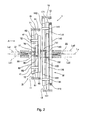
FIG. 2 is a conceptual view that shows the basic configuration of the speed reducing gear; -
FIG. 3 is a view when seen in the direction of the arrow A inFIG. 2 through part of a first change gear unit; -
FIG. 4 is a graph that shows the correlation between the transmission ratio and the transmission efficiency; -
FIG. 5 is a table that shows the transmission ratio, the speed reduction efficiency and the speed increasing efficiency with respect to the number of change gear units (n); -
FIG. 6 is a sectional view that shows the configuration of a speed reducing gear according to a second embodiment; -
FIG. 7 is a conceptual view that shows the basic configuration of the speed reducing gear according to the second embodiment; -
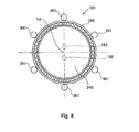
FIG 8 is a sectional view that is taken along the line B-B inFIG. 7 ; -
FIG 9 is a sectional view that shows the configuration of a modified example of the second embodiment; -
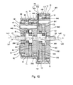
FIG 10 is a sectional view that shows the configuration of a speed reducing gear according to a third embodiment; -
FIG. 11 is a conceptual view that shows the basic configuration of the speed reducing gear according to the third embodiment; and -
FIG 12 is a sectional view that is taken along the line C-C inFIG. 11 . - Hereinafter, embodiments of the invention will be described with reference to the accompanying drawings.
- A
speed reducing gear 1, according to a first embodiment will be described with reference toFIG 1 to FIG. 5 .FIG. 1 is a sectional view that shows the configuration of thespeed reducing gear 1.FIG. 2 is a conceptual view that shows the basic configuration of thespeed reducing gear 1.FIG. 3 is a view when seen in the direction of the arrow A inFIG. 2 through part of a firstchange gear unit 31.FIG 4 is a graph that shows the correlation between the transmission ratio and the transmission efficiency.FIG. 5 is a table that shows the transmission ratio, the speed reduction efficiency and the speed increasing efficiency with respect to the number of change gear units (n). Note that, in the sectional view ofFIG. 1 , some parts of the configuration of thespeed reducing gear 1, for example, pins 41, 141 located on the lower side ofFIG 1 are omitted for the sake of convenience. - The
speed reducing gear 1 is mainly formed of ahousing 10, aninput shaft member 21, anoutput shaft member 22, the firstchange gear unit 31, a secondchange gear unit 32, a firstpin support member 81, a secondpin support member 82 andbearings 91 to 93. - As shown in
FIG. 1 , thehousing 10 is a case that supports theinput shaft member 21 and theoutput shaft member 22 rotatably about a common input/output axis Lo, and that accommodates a plurality of change gear units, that is, the first and secondchange gear units housing 10 has a firstinternal gear 11 and a secondinternal gear 12 on its inner peripheral surface. The firstinternal gear 11 and the secondinternal gear 12 extend in a direction along the input/output axis Lo, and have different inside diameters. The firstinternal gear 11 is located at one side (left side inFIG 1 andFIG. 2 ) of thespeed reducing gear 1, with respect to the secondinternal gear 12. The inside diameter of the firstinternal gear 11 is smaller than the inside diameter of the secondinternal gear 12. - The
input shaft member 21 is an input shaft that is coupled to a motor (not shown), and that is rotated when the motor is driven. Theinput shaft member 21 is rotatably supported by thehousing 10 via the first pin support member 81 (described later). Thus, theinput shaft member 21 is rotatable about the input/output axis Lo. In addition, theinput shaft member 21 is arranged at one side of thespeed reducing gear 1, and the other side (right side inFIG. 1 andFIG 2 ) end portion of theinput shaft member 21 is coupled to acrankshaft 50 of the first change gear unit 31 (described later). - The
output shaft member 22 is an output shaft that outputs rotation of which the speed is reduced by the first and secondchange gear units output shaft member 22 is arranged at the other side of thespeed reducing gear 1, and one side end portion of theoutput shaft member 22 is coupled to a rotatingmember 140 of the second change gear unit 32 (described later). That is, theoutput shaft member 22 is rotatably supported by thehousing 10 via the rotatingmember 140 of the second change gear unit 32 (described later). Thus, theoutput shaft member 22 is rotatable about the input/output axis Lo. - As shown in
FIG. 1 andFIG 2 , the firstchange gear unit 31 is formed of a rotatingmember 40, thecrankshaft 50, a first oscillatingmember 60 and a second oscillatingmember 70. Similarly, the secondchange gear unit 32 is formed of the rotatingmember 140, acrankshaft 150, a first oscillatingmember 160 and a second oscillatingmember 170. However, in the present embodiment, the rotatingmember 40 of the firstchange gear unit 31 and thecrankshaft 150 of the secondchange gear unit 32 are integrally formed and serve as a single member. Then, inFIG. 1 , thecrankshaft 150 of the secondchange gear unit 32 is indicated as the rotatingmember 40. In addition, in the conceptual view ofFIG. 2 , the rotatingmember 40 and thecrankshaft 150 are separately shown. - The thus configured first and second
change gear units side crankshafts side rotating members speed reducing gear 1, the firstchange gear unit 31 is a change gear unit arranged at the input side, and the secondchange gear unit 32 is a change gear unit arranged at the output side. That is, the firstchange gear unit 31 and the secondchange gear unit 32 are arranged so as to be next to each other in the direction along the input/output axis Lo. The firstchange gear unit 31 corresponds to "one side change gear unit" according to the invention, and the secondchange gear unit 32 corresponds to "the other side change gear unit" according to the invention. Hereinafter, the configuration of the firstchange gear unit 31 will be described. - As described above, the rotating
member 40 is a disc-shaped member that is integrally formed with thecrankshaft 150 of the secondchange gear unit 32. As shown inFIG 1 , the rotatingmember 40 is supported by thehousing 10 via the rotatingmember 140 of the secondchange gear unit 32 rotatably about the input/output axis Lo. The rotatingmember 40 of the firstchange gear unit 31 has thepins 41,roller bearings 42, a recessedportion 43, a firsteccentric portion 151, a secondeccentric portion 152 and a projectingportion 153. The firsteccentric portion 151 and the secondeccentric portion 152 correspond to an "eccentric member" according to the invention. - The
pins 41 are formed so as to protrude from one side disc surface of the rotatingmember 40 in the direction along the input/output axis Lo. As shown inFIG. 3 , the sixpins 41 are fixed to the one side disc surface of the rotatingmember 40 so as to be arranged at equiangular positions in the circumferential direction of the rotatingmember 40. Each of thepins 41 is a columnar member that is fixed to the rotatingmember 40. Each of theroller bearings 42 is a cylindrical bearing member that is rotatably fitted around a corresponding one of thepins 41. Eachpin 41 is inserted through insertion holes 62 and 72 of the first and second oscillatingmembers 60 and 70 (described later). Part of eachroller bearing 42 fitted around a corresponding one of thepins 41 is in contact with the inner peripheral surfaces of these insertion holes 62 and 72. - The recessed
portion 43 is a cylindrical inner surface. The recessedportion 43 is formed in the rotatingmember 40 so as to extend from the disc surface at the one side of thespeed reducing gear 1 toward the other side. The recessedportion 43 centers on the input/output axis Lo. The projectingportion 53 is formed at the output side end portion of thecrankshaft 50 of the first change gear unit 31 (described later). The projectingportion 53 is inserted in the recessedportion 43. The recessedportion 43 supports thecrankshaft 50 such that thecrankshaft 50 is rotatable relative to the recessedportion 43. - The first
eccentric portion 151 and secondeccentric portion 152 of the rotatingmember 40 are located on a side toward which thepins 141 protrude (left side inFIG. 1 ) with respect to the rotatingmember 140 of the secondchange gear unit 32. The sectional shape of the firsteccentric portion 151 is a perfect circle that centers on a first eccentric axis La2 of the secondchange gear unit 32, which is eccentric in the radial direction of the rotatingmember 40 with respect to the input/output axis Lo. The sectional shape of the secondeccentric portion 152 is a perfect circle that centers on a second eccentric axis Lb2 of the secondchange gear unit 32, which is eccentric in the radial direction of the rotatingmember 40 with respect to the input/output axis Lo, as in the case of the firsteccentric portion 151. - The first and second
eccentric portions member 160 and second oscillatingmember 170 of the secondchange gear unit 32, respectively. In this way, the rotatingmember 40 of the firstchange gear unit 31 is configured such that the first and secondeccentric portions change gear unit 32 are integrally provided at locations eccentric in the radial direction. - The projecting
portion 153 is a cylindrical portion that projects from the other side disc surface of the rotatingmember 40 toward the output side and that centers on the input/output axis Lo. As shown inFIG. 1 , the projectingportion 153 is inserted in a recessedportion 143 of the rotatingmember 140 of the second change gear unit 32 (described later). Thus, the rotatingmember 40 is supported so as to be rotatable relative to the rotatingmember 140 of the secondchange gear unit 32. In this way, the rotatingmember 40 of the firstchange gear unit 31 also serves as the crankshaft. 150 of the secondchange gear unit 32, which is integrally formed with the rotatingmember 40. - The
crankshaft 50 has a firsteccentric portion 51, a secondeccentric portion 52 and the projectingportion 53. The firsteccentric portion 51 has an eccentric shape that is eccentric with respect to the axis of the crankshaft 50 (input/output axis Lo). The firsteccentric portion 51 is arranged on a side toward which thepins 41 protrude (left side inFIG. 1 ) with respect to the rotatingmember 40, and is integrally formed with thecrankshaft 50. In addition, the sectional shape of the firsteccentric portion 51 is a perfect circle that centers on a first eccentric axis La1 that is eccentric in the radial direction of thecrankshaft 50 with respect to the input/output axis Lo. The firsteccentric portion 51 rotates about the input/output axis Lo as thecrankshaft 50 rotates about the input/output axis Lo. - The second
eccentric portion 52 as well as the firsteccentric portion 51 has an eccentric shape that is eccentric with respect to the axis of the crankshaft 50 (input/output axis Lo). The secondeccentric portion 52 is arranged on a side toward which thepins 41 protrude (left side inFIG. 1 ) with respect to the rotatingmember 40, and is arranged on the output side with respect to the first eccentric portion 51 (right side of the firsteccentric portion 51 inFIG. 1 ). The secondeccentric portion 52 and the firsteccentric portion 51 are coupled to each other, and are integrally formed with thecrankshaft 50. In addition, the sectional shape of the secondeccentric portion 52 has a perfect circle that centers on a second eccentric axis Lb1 that is eccentric in the radial direction of thecrankshaft 50 with respect to the input/output axis Lo. The secondeccentric portion 52 rotates about the input/output axis Lo as thecrankshaft 50 rotates about the input/output axis Lo. - The first
eccentric portion 51 and the secondeccentric portion 52 are coupled to each other such that their eccentric directions with respect to the input/output axis Lo are opposite to each other. In other words, in the present embodiment, the firsteccentric portion 51 and the secondeccentric portion 52 that are two eccentric members are coupled to each other at an interval of 180 degrees so as to be arranged at equiangular positions in the circumferential direction of rotation about the input/output axis Lo. - The projecting
portion 53 has a columnar shape that centers on the input/output axis Lo, and is formed so as to protrude from an end surface of the secondeccentric portion 52 at the output side end portion of thecrankshaft 50. The projectingportion 53 is inserted in the recessedportion 43 of the rotatingmember 40, and is rotatably supported by the rotatingmember 40. Thus, thecrankshaft 50 is supported via the rotatingmember 40 by the rotatingmember 140 of the secondchange gear unit 32 that supports the rotatingmember 40. - In addition, one side (left side in
FIG. 1 ) end portion of thecrankshaft 50 of the firstchange gear unit 31 is coupled to theinput shaft member 21. Thus, thecrankshaft 50 rotates about the input/output axis Lo as theinput shaft member 21 rotates. In addition, with the above configuration, the firsteccentric portion 51 and secondeccentric portion 52 of the firstchange gear unit 31 that serves as the one side change gear unit are coupled to theinput shaft member 21 via thecrankshaft 50. - The first oscillating
member 60 has an annular shape. As shown inFIG. 1 andFIG 2 , the first oscillatingmember 60 is a planet gear that has anexternal gear 61 and insertion holes 62 and that is rotatably supported on the outer peripheral side of the firsteccentric portion 51. Theexternal gear 61 is formed on the outer peripheral surface of the first oscillatingmember 60, and is in mesh with the firstinternal gear 11 of thehousing 10. Each of thepins 41 of the rotatingmember 40 is inserted in a corresponding one of the insertion holes 62. The inside diameter of eachinsertion hole 62 of the first oscillatingmember 60 is substantially equal to the sum of the diameter of the insertedpin 41 and the eccentric amount (distance between the input/output axis Lo and the first eccentric axis La1) of the first oscillatingmember 60. Here, because theroller bearing 42 is fitted around eachpin 41 in the present embodiment, the above "diameter of eachpin 41" substantially corresponds to the diameter of eachroller bearing 42. - More specifically, the inner peripheral surfaces of the insertion holes 62 of the first oscillating
member 60 contact the outer peripheral surfaces of theroller bearings 42 fitted around therespective pins 41 to transmit driving force in a state where thespeed reducing gear 1 is driven. With the above configuration, the first oscillatingmember 60 oscillatingly rotates so as to revolve around the input/output axis Lo while rotating about the first eccentric axis La1 as the firsteccentric portion 51 rotates about the input/output axis Lo. Then, the axial rotation component of the oscillatingly rotating first oscillatingmember 60 is transmitted to thepins 41, and the rotatingmember 40 rotates at the rotational speed at which the first oscillatingmember 60 rotates on its axis. - The second oscillating
member 70 as well as the first oscillatingmember 60 has an annular shape. As shown inFIG. 1 andFIG. 2 , the second oscillatingmember 70 is a planet gear that has anexternal gear 71 and insertion holes 72, and that is rotatably supported on the outer peripheral side of the secondeccentric portion 52. Theexternal gear 71 is formed on the outer peripheral surface of the second oscillatingmember 70, and is in mesh with the firstinternal gear 11 of thehousing 10. Each of thepins 41 of the rotatingmember 40 is inserted in a corresponding one of the insertion holes 72. The inside diameter of eachinsertion hole 72 of the second oscillatingmember 70 is substantially equal to the sum of the diameter of each insertedpin 41 and the eccentric amount (distance between the input/output axis Lo and the second eccentric axis Lb1) of the second oscillatingmember 70. The "diameter of eachpin 41 corresponds to the diameter of eachroller bearing 42 in the present embodiment as described above. - More specifically, the inner peripheral surfaces of the insertion holes 72 of the second oscillating
member 70 contact the outer peripheral surfaces of theroller bearings 42 fitted around therespective pins 41 to transmit driving force in a state where thespeed reducing gear 1 is driven. With the above configuration, the second oscillatingmember 70 oscillatingly rotates so as to revolve around the input/output axis Lo while rotating about the second eccentric axis Lb1 as the secondeccentric portion 52 rotates about the input/output axis Lo. Then, the axial rotation component of the oscillatingly rotating second oscillatingmember 70 is transmitted to thepins 41, and the rotatingmember 40 rotates at the rotational speed at which the second oscillatingmember 70 rotates on its axis. - In addition, the first
eccentric portion 51 and secondeccentric portion 52 of thecrankshaft 50 are coupled to each other so as to be arranged at equiangular positions in the circumferential direction of rotation about the input/output axis Lo. Thus, the first and second oscillatingmembers eccentric portions speed reducing gear 1 is driven, the first and secondeccentric portions crankshaft 50 and then the first and second oscillatingmembers eccentric portions oscillating numbers - As described above, the first
change gear unit 31 is formed of the rotatingmember 40, thecrankshaft 50, the first oscillatingmember 60 and the second oscillatingmember 70. In addition, the secondchange gear unit 32 is provided at the output side of thespeed reducing gear 1 so as to be next to the firstchange gear unit 31. The secondcharge gear unit 32 is formed of the rotatingmember 140, the crankshaft 150 (the rotatingmember 40 of the first change gear unit 31), the first oscillatingmember 160 and the second oscillatingmember 170, which have shapes different from those of the firstchange gear unit 31. - The rotating
member 140 of the secondchange gear unit 32 is a disc-shaped member that is supported by thehousing 10 via thebearing 91 so as to be rotatable about the input/output axis Lo. The rotatingmember 140 of the secondchange gear unit 32 has thepins 141,roller bearings 142 and the recessedportion 143. Because thepins 141 and theroller bearings 142 respectively correspond to thepins 41 androller bearings 42 of the rotatingmember 40 of the firstchange gear unit 31, the detailed description thereof is omitted. - The recessed
portion 143 is a cylindrical inner surface. The recessedportion 143 is formed in the rotatingmember 140 so as to extend from the disc surface at the one side of thespeed reducing gear 1 toward the other side. The recessedportion 143 centers on the input/output axis Lo. The projectingportion 153 of the rotatingmember 40 of the firstchange gear unit 31 is inserted in the recessedportion 143. The recessedportion 143 supports the rotatingmember 40 of the firstchange gear unit 31, which is integrally formed with thecrankshaft 150 of the secondchange gear unit 32, such that the rotatingmember 40 is rotatable relative to the recessedportion 143. In addition, the other side disc surface of the rotatingmember 140 is coupled to theoutput shaft member 22. - In addition, the
crankshaft 150 of the secondchange gear unit 32 is integrally formed with the rotatingmember 40 of the firstchange gear unit 31 as described above. In the present embodiment, when thecrankshaft 150 is formed in this way, the rotatingmember 40 of the firstchange gear unit 31 is coupled to the firsteccentric portion 151 and the secondeccentric portion 152 that correspond to the eccentric members of the secondchange gear unit 32. Thus, the secondchange gear unit 32 is coupled to theinput shaft member 21 via the firstchange gear unit 31. - The first oscillating
member 160 has an annular shape. As shown inFIG. 1 andFIG. 2 , the first oscillatingmember 160 is a planet gear that has anexternal gear 161 andinsertion holes 162, and that is rotatably supported on the outer peripheral side of the firsteccentric portion 151. Theexternal gear 161 is formed on the outer peripheral surface of the first oscillatingmember 160, and is able to be in mesh with the secondinternal gear 12 of thehousing 10. Each of thepins 141 of the rotatingmember 140 is inserted in a corresponding one of the insertion holes 162. The inside diameter of eachinsertion hole 162 of the first oscillatingmember 160 is substantially equal to the sum of the diameter of the insertedpin 141 and the eccentric amount (distance between the input/output axis Lo and the first eccentric axis La2) of the first oscillatingmember 160. Here, because theroller bearing 142 is fitted around eachpin 141 in the present embodiment, the above "diameter of eachpin 141" substantially corresponds to the diameter of eachroller bearing 142. - More specifically, the inner peripheral surfaces of the insertion holes 162 of the first oscillating
member 160 contact the outer peripheral surfaces of theroller bearings 142 fitted around thepins 141 to transmit driving force in a state where thespeed reducing gear 1 is driven. With the above configuration, the first oscillatingmember 160 oscillatingly rotates so as to revolve around the input/output axis Lo while rotating about the first eccentric axis La2 as the firsteccentric portion 151 rotates about the input/output axis Lo. Then, the axial rotation component of the oscillatingly rotating first oscillatingmember 160 is transmitted to thepins 141, and the rotatingmember 140 rotates at the rotational speed at which the first oscillatingmember 160 rotates on its axis. - The second
oscillating member 170 as well as the first oscillatingmember 160 has an annular shape. As shown inFIG. 1 andFIG. 2 , the second oscillatingmember 170 is a planet gear that has anexternal gear 171 andinsertion holes 172, and that is rotatably supported on the outer peripheral side of the secondeccentric portion 152. Theexternal gear 171 is formed on the outer peripheral surface of the second oscillatingmember 170, and is in mesh with the secondinternal gear 12 of thehousing 10. Each of thepins 141 of the rotatingmember 140 is inserted in a corresponding one of the insertion holes 172. The inside diameter of eachinsertion hole 172 of the second oscillatingmember 170 is substantially equal to the sum of the diameter of each insertedpin 141 and the eccentric amount (distance between the input/output axis Lo and the second eccentric axis Lb2) of the second oscillatingmember 170. The "diameter of eachpin 141" corresponds to the diameter of eachroller bearing 142 in the present embodiment as described above. - More specifically, the inner peripheral surfaces of the insertion holes 172 of the second oscillating
member 170 contact the outer peripheral surfaces of theroller bearings 142 fitted around therespective pins 141 to transmit driving force in a state where thespeed reducing gear 1 is driven. With the above configuration, the second oscillatingmember 170 oscillatingly rotates so as to revolve around the input/output axis Lo while rotating around the second eccentric axis Lb2 as the secondeccentric portion 152 rotates about the input/output axis Lo. Then, the axial rotation component of the oscillatingly rotating second oscillatingmember 170 is transmitted to thepins 141, and the rotatingmember 140 rotates at the rotational speed at which the second oscillatingmember 170 rotates on its axis. - In addition, the first
eccentric portion 151 and secondeccentric portion 152 of thecrankshaft 150 that is integrally formed with the rotatingmember 40 of the firstchange gear unit 31 are coupled to each other so as to be arranged at equiangular positions in the circumferential direction of rotation about the input/output axis Lo. Thus, the first and second oscillatingmembers eccentric portions - In a state where the
speed reducing gear 1 is driven, the first and secondeccentric portions crankshaft 150 and then the first and second oscillatingmembers eccentric portions members - With the above configuration, inside the
housing 10, the firstchange gear unit 31 and the secondchange gear unit 32 are located so as to be next to each other in the direction along the input/output axis Lo. Then, theexternal gear 61 of the first oscillatingmember 60 and theexternal gear 71 of the second oscillatingmember 70 in the firstchange gear unit 31 are in mesh with the firstinternal gear 11. In contrast to this, theexternal gear 161 of the first oscillatingmember 160 and theexternal gear 171 of the second oscillatingmember 170 in the secondchange gear unit 32 are in mesh with the secondinternal gear 12. - In this way, the first
change gear unit 31 and the secondchange gear unit 32 are respectively arranged at locations, at which the first and secondinternal gears external gears external gears internal gear 11 and the secondinternal gear 12 that have different inside diameters. Then, the first and secondchange gear units internal gear 11 and the secondinternal gear 12 and change the speed of rotation transmitted from theinput shaft member 21 to theoutput shaft member 22. - The first
pin support member 81 is a disc-shaped member that is supported by thehousing 10 via thebearing 92 so as to be rotatable about the input/output axis Lo. The firstpin support member 81 is arranged on a side toward which thepins 41 of the rotatingmember 40 protrude with respect to the first and secondeccentric portions change gear unit 31. Then, the firstpin support member 81 has pin holes that are equal in number to the plurality ofpins 41. The end portions of thepins 41 that are inserted through the insertion holes 62 and 72 of the first and second oscillatingmembers pin support member 81 supports the sixpins 41 fixed to the rotatingmember 40, and rotates at the same rotational speed as the rotatingmember 40 with the rotation of the rotatingmember 40. In addition, the firstpin support member 81 rotatably supports theinput shaft member 21 via a bearing arranged on the cylindrical inner surface of the firstpin support member 81. - The second
pin support member 82 is a disc-shaped member that is supported by thehousing 10 via thebearing 93 so as to be rotatable about the input/output axis Lo. The secondpin support member 82 is arranged on a side toward which thepins 141 of the rotatingmember 140 protrude with respect to the first and secondeccentric portions change gear unit 32. Then, the secondpin support member 82 has pin holes that are equal in number to the plurality ofpins 141. The end portions of thepins 141 that are inserted through the insertion holes 162 and 172 of the first and second oscillatingmembers pin support member 82 supports the sixpins 141 fixed to the rotatingmember 140, and rotates at the same rotational speed as the rotatingmember 140 with the rotation of the rotatingmember 140. - Subsequently, the operation of the
speed reducing gear 1 according to the present embodiment will be described. First, as the motor (not shown) is operated, theinput shaft member 21 coupled to the motor rotates. As theinput shaft member 21 rotates, thecrankshaft 50 of the firstchange gear unit 31 coupled to theinput shaft member 21 rotates about the input/output axis Lo. Thus, the firsteccentric portion 51 and the secondeccentric portion 52 that constitute thecrankshaft 50 rotate. - Then, the first oscillating
member 60 supported on the outer peripheral side of the firsteccentric portion 51 oscillatingly rotates as the firsteccentric portion 51 rotates. Similarly, the second oscillatingmember 70 supported on the outer peripheral side of the secondeccentric portion 52 oscillatingly rotates as the secondeccentric portion 52 rotates. At this time, only parts of the circumferences of the respectiveexternal gears member 60 and second oscillatingmember 70 are in mesh with the firstinternal gear 11 of thehousing 10, and the first oscillatingmember 60 and the second oscillatingmember 70 rotate at a rotational speed based on the difference in the number of teeth from the firstinternal gear 11 in a direction opposite to the direction in which theinput shaft member 21 rotates (that is, the counterclockwise direction when theinput shaft member 21 rotates in the clockwise direction). - Here, each
pin 41 of the rotatingmember 40 is inserted in a corresponding one of the insertion holes 62 of the first oscillatingmember 60 and a corresponding one of the insertion holes 72 of the second oscillatingmember 70. Then, only parts of the circumferences of the outer peripheral surfaces of theroller bearings 42 fitted around thepins 41 contact the inner peripheral surfaces of the insertion holes 62 and 72 to transmit driving force. Thus, as the first and second oscillatingmembers pins 41. Then, the rotatingmember 40 rotates at a rotational speed at which the first and second oscillatingmembers member 40 extracts the axial rotation component from the oscillating rotations of the first and second oscillatingmembers pins 41 and theroller bearings 42, and the firstchange gear unit 31 reduces the speed of rotation input into thecrankshaft 50 and then outputs the rotation from the rotatingmember 40. - After that, as the rotating member 40 (
crankshaft 150 of the second change gear unit 32) of the firstchange gear unit 31 rotates, the firsteccentric portion 151 and the secondeccentric portion 152 that constitute thecrankshaft 150 of the secondchange gear unit 32 rotate. Then, the secondchange gear unit 32, as well as the firstchange gear unit 31, reduces the speed of rotation input into thecrankshaft 150 and then outputs the rotation from the rotatingmember 140. Thus, theoutput shaft member 22 coupled to the rotatingmember 140 of the secondchange gear unit 32 rotates around the input/output axis Lo. - As described above, the
speed reducing gear 1 according to the present embodiment uses the plurality of change gear units, that is, the firstchange gear unit 31 and the secondchange gear unit 32, to reduce the speed of rotation input into theinput shaft member 21 in two stages and then output the rotation from theoutput shaft member 22. Setting the number of teeth of each of the gears in the thus configuredspeed reducing gear 1 will be described. - Where the number of teeth of the first
internal gear 11 of thehousing 10 is Z1 and the number of teeth of each of theexternal gears members change gear unit 31 is Z2, the speed reducing ratio R1 of the firstchange gear unit 31 is calculated by the mathematical expression 1). Similarly, where the number of teeth of the secondinternal gear 12 of thehousing 10 is Z3 and the number of teeth of each of theexternal gears members change gear unit 32 is Z4, the speed reducing ratio R2 of the secondchange gear unit 32 is calculated by the mathematical expression 2). Then, the speed reducing ratio R of thespeed reducing gear 1 is calculated by the mathematical expression 3). -


- There is a known fact that, as the transmission ratio of a speed change gear or the transmission ratio of a change gear unit increases, the transmission efficiency decreases, as shown in
FIG. 4 . The transmission ratio is calculated as the inverse number of the speed reducing ratio, and indicates the change gear ratio of the speed change gear. In addition, as the transmission efficiency decreases to a certain value or below, self-lock may occur in the speed change gear. Therefore, the transmission efficiency is desirably as high as possible. - For example, in a case where the transmission ratio of the
speed reducing gear 1 is 169 (1/169 in the speed reducing ratio), when the number of teeth with which the above transmission ratio is obtained in a single-stage is set, the transmission efficiency is about 50%. Then, in the present embodiment, the number of teeth Z1 of the firstinternal gear 11 is set to 126, and the number of teeth Z2 of each of theexternal gears change gear unit 31 is set to 117. Then, the number of teeth Z3 of the secondinternal gear 12 is set to 224, and the number of teeth Z4 of each of theexternal gears change gear unit 32 is set to 208. - Thus, as shown in
FIG 5 , the first and secondchange gear units 31 and 32 (n = 1) each are able to obtain a transmission ratio of 13 and a transmission efficiency (speed reducing efficiency) of about 92%. Then, the speed reducing gear 1 (n = 2) is able to obtain a transmission ratio of 169 (speed reducing ratio R is 1/169) and a transmission efficiency of about 85%. n inFIG 5 indicates the number of change gear units. In this way, the numbers of teeth of the gears in thespeed reducing gear 1 are set so as to be able to obtain a predetermined transmission ratio R in consideration of reduction in speed over multiple stages. - The
speed reducing gear 1 to which the speed change gear according to the invention is applied includes thehousing 10 and the first and secondchange gear units internal gears housing 10. The rotatingmember 40 of the firstchange gear unit 31 and thecrankshaft 150 of the secondchange gear unit 32 are integrally formed with each other. Thus, the rotatingmember 40 of the one side change gear unit (first change gear unit 31) and the firsteccentric portion 151 and secondeccentric portion 152 of the other side change gear unit (second change gear unit 32), which are next to each other, are coupled to each other. - Thus, a high change gear ratio may be obtained by the first and second
change gear units external gears change gear unit 31 and theexternal gears change gear unit 32 are respectively in mesh are the first and secondinternal gears housing 10. - The speed change gear is required to have a mechanical strength corresponding to input driving force in order to deal with, for example, the input driving force or an increase in the driving force due to gear change. Therefore, in a case where the speed of rotation is reduced so as to generate high driving force, for example, the pitch circle diameter of each of the meshed internal gear and external gear may be increased to suppress pressure applied to tooth surfaces. However, when the plurality of speed reducing gears having different pitch circle diameters are coupled to each other in tandem as in the case of the related art, there is a possibility that the number of components of the speed reducing gear increases and the size of the speed reducing gear increases as a whole.
- Therefore, with the above configuration, the first and second
internal gears same housing 10, and the first and secondchange gear units internal gears change gear units change gear units speed reducing gear 1 and to simplify thespeed reducing gear 1. Thus, in a driving state where thespeed reducing gear 1 is transmitting driving force, a mechanical loss due to transmission of driving force is reduced to make it possible to improve the transmission efficiency. - In addition, the first and second
change gear units internal gears housing 10. Thus, in comparison with the configuration where a plurality of speed reducing gears are coupled to each other, it is possible to easily obtain a high change gear ratio. Then, in this case, because first and secondchange gear units speed reducing gear 1 may be reduced as a whole. Here, there is a generally known fact that the transmission efficiency reduces if a high change gear ratio is attempted to be obtained. Then, the first and secondchange gear units change gear units - In addition, the first
change gear unit 31 includes the first and secondeccentric portions members eccentric portions external gears members change gear unit 31 may be dispersed. Thus, with the firstchange gear unit 31, it is possible to increase the mechanically transmittable maximum driving force. In addition, a similar advantageous effect may be obtained in the secondchange gear unit 32 that includes the first and secondeccentric portions members - Furthermore, the first
eccentric portion 51 and the secondeccentric portion 52 in the firstchange gear unit 31 are coupled to theinput shaft member 21 via the crankshaft. 50 such that the first and second oscillatingmembers eccentric portions eccentric portion 51 and the secondeccentric portion 52 are coupled to each other in the direction along the input/output axis Lo such that the first and second oscillatingmembers eccentric portion 51 and secondeccentric portion 52. - In addition, the first
eccentric portion 151 and secondeccentric portion 152 of the secondchange gear unit 32 are coupled to theinput shaft member 21 via thecrankshaft 150 and the firstchange gear unit 31 such that the first and second oscillatingmembers change gear units speed reducing gear 1. - The rotating
member 40 of the firstchange gear unit 31 is integrally formed with thecrankshaft 150 of the secondchange gear unit 32. That is, the first and secondeccentric portions change gear unit 32 are integrally coupled to the rotatingmember 40 at locations that are eccentric in the radial direction. Thus, the first and second oscillatingmembers change gear unit 32 are rotatably supported on the outer peripheral surface of the rotatingmember 40 of the firstchange gear unit 31. With the above configuration, the rotatingmember 40 of the firstchange gear unit 31 has the functions as the first and secondeccentric portions change gear unit 32, and is formed as a single member. Thus, the number of components may be reduced. Furthermore, in comparison with the case where the first and secondchange gear units speed reducing gear 1 along the input/output axis Lo may be reduced. Therefore, the size of thespeed reducing gear 1 may be reduced as a whole. - The
speed reducing gear 1 includes the firstpin support member 81 that supports thepins 41 inserted through the insertion holes 62 and 72 of the first and second oscillatingmembers change gear unit 31. Similarly, thespeed reducing gear 1 includes the secondpin support member 82 that supports thepins 141 inserted through the insertion holes 162 and 172 of the first and second oscillatingmembers change gear unit 32. With the above configuration, both end portions of each of thepins 41 of the rotatingmember 40 of the firstchange gear unit 31 are supported respectively by the rotatingmember 40 and the firstpin support member 81, and both end portions of each of thepins 141 of the rotatingmember 140 of the secondchange gear unit 32 are respectively supported by the rotatingmember 140 and the secondpin support member 82. - The
pins 41 of the rotatingmember 40 output the axial rotation component of the oscillatingly rotating first and second oscillatingmembers pins 141 of the rotatingmember 140 output the axial rotation component of the oscillatingly rotating first and second oscillatingmembers eccentric portions speed reducing gear 1 is driven, the rotatingmember 40 may be influenced by the oscillating rotations of the first and second oscillatingmembers eccentric portions speed reducing gear 1 is driven, the rotatingmember 140 may be influenced by the oscillating rotations of the first and second oscillatingmembers pins rotating members pin support members rotating members - In the present embodiment, the first and second
pin support members pins 41 of the firstchange gear unit 31, which rotates at a particularly high speed in a state where thespeed reducing gear 1 is driven, at both ends using, for example, the above firstpin support member 81 is useful. The number ofteeth 21 of the firstinternal gear 11 is larger than the number of teeth Z2 of each of theexternal gears input shaft member 21 that is coupled to the first and secondeccentric portions 51 and 52-side of the firstchange gear unit 31 rotates at a speed higher than that of theoutput shaft member 22 that is coupled via the secondchange gear unit 32 to the rotating member 40-side. - Then, in the
speed reducing gear 1 to which the speed change gear according to the invention is applied, in a state where thespeed reducing gear 1 is driven, the firstchange gear unit 31 that is located at the input shaft member 21-side rotates at a speed higher than that of the secondchange gear unit 32. As described above, there is a possibility that the rotatingmember 40 wobbles due to the influence of oscillating rotations of the first and second oscillatingmembers eccentric portions pins 41 of the high rotational speed-side rotating member 40 within the first and secondchange gear units pin support member 81. This configuration prevents the wobbling of the rotatingmember 40, and the like, and may be applied to transmission of driving force at a higher rotational speed. - In addition, the first
pin support member 81 supports thepins 41 at both ends in cooperation with the rotatingmember 40, and supports the plurality ofpins 41 so as to maintain the intervals between thepins 41. Similarly, the secondpin support member 82 supports thepins 141 at both ends in cooperation with the rotatingmember 140, and supports the plurality ofpins 141 so as to maintain the intervals between thepins 141. Thus, even when driving force transmitted in a state where thespeed reducing gear 1 is driven is exerted on the plurality ofpins 41 or the plurality ofpins 141, the intervals between thepins 41 or thepins 141 are maintained. Therefore, it is possible to prevent driving force exerted on the plurality ofpins certain pin speed reducing gear 1. - The configuration of the second embodiment will be described with reference to
FIG. 6 to FIG. 8 .FIG. 6 is a sectional view that shows the configuration of aspeed reducing gear 101.FIG. 7 is a conceptual view that shows the basic configuration of thespeed reducing gear 101.FIG. 8 is a sectional view taken along the line B-B inFIG. 7 . The second embodiment mainly differs from the first embodiment in the configuration of the first and secondchange gear units FIG. 6 , some parts of the configuration of thespeed reducing gear 101, for example, pins 41, 341 located on the lower side ofFIG. 6 are omitted. In addition, the other configuration is the same as that of the first embodiment. Therefore, the detailed description thereof is omitted. Hereinafter, only the difference will be described. - The
speed reducing gear 101 is mainly formed of ahousing 10, aninput shaft member 21, anoutput shaft member 22, a firstchange gear unit 131, a secondchange gear unit 132, a firstpin support member 81, apin retaining member 83 andbearings FIG. 6 andFIG. 7 , the firstchange gear unit 131 is a unit that is formed of a rotatingmember 240, acrankshaft 250, a first oscillatingmember 60 and a second oscillatingmember 70. Similarly, the secondchange gear unit 132 is a unit that is formed of a rotatingmember 340, acrankshaft 350, a first oscillatingmember 160 and a second oscillatingmember 170. - In the first embodiment, the rotating
member 40 of the firstchange gear unit 31 and thecrankshaft 150 of the secondchange gear unit 32 are integrally formed with each other. In contrast to this, the first and secondchange gear units member 240 and the crankshaft 350) are arranged in the direction along the input/output axis Lo and are coupled to each other. Thus, the second embodiment differs from the first embodiment in that the rotatingmember 240 of the firstchange gear unit 131 is coupled to theoutput shaft member 22 via the secondchange gear unit 132. - In addition, in the first embodiment, the rotating
member 40 of the firstchange gear unit 31 is rotatably supported when the projectingportion 153 of the rotatingmember 40 is inserted in the recessedportion 143 of the rotatingmember 140 of the secondchange gear unit 32. In contrast to this, the rotatingmember 240 of the firstchange gear unit 131 according to the present embodiment differs from the rotatingmember 40 of the first embodiment in that the outer peripheral surface of the rotatingmember 240 is supported by thepins 341 of the rotatingmember 340 of the secondchange gear unit 132. - Furthermore, in the first embodiment, the
pins 141 of the secondchange gear unit 32 each are supported at both ends by the rotatingmember 140 and the secondpin support member 82. In contrast to this, thepins 341 of the secondchange gear unit 131 according to the present embodiment differ from thepins 141 according to the first embodiment in that the input-side end portions are retained by thepin retaining member 83. - The rotating
member 240 of the firstchange gear unit 131 has thepins 41 and theroller bearings 42, and abearing 193 is fitted around the outer peripheral surface of the rotatingmember 240 as shown inFIG. 8 . The outer peripheral surface of thebearing 193 is in contact with thepins 341 of the rotatingmember 340 of the secondchange gear unit 132. Thus, the rotatingmember 240 is rotatably supported by thepins 341 via thebearing 193. Thecrankshaft 250 of the firstchange gear unit 131 has a firsteccentric portion 51 and a secondeccentric portion 52. The input-side end portion of thecrankshaft 250 is coupled to theinput shaft member 21. - The rotating
member 340 of the secondchange gear Unit 132 has thepins 341 androller bearings 342. Thepins 341 are formed so as to protrude from one side disc surface of the rotatingmember 340 in the direction along the input/output axis Lo. As shown inFIG 8 , the sixpins 341 are fixed to the disc surface so as to be arranged at equiangular positions in the circumferential direction of rotation about the input/output axis Lo. - Each of the
pins 341 is a columnar member that is fixed to the rotatingmember 340. Each of theroller bearings 342 is a cylindrical member that is rotatably fitted around a corresponding one of thepins 341. Eachpin 341 is inserted throughinsertion holes members roller bearing 342 fitted around a corresponding one of thepins 341 is in contact with the inner peripheral surfaces of theseinsertion holes pin 341 is inserted through the insertion holes 162 and 172 and is in contact with the outer peripheral surface of thebearing 193 to thereby rotatably support the rotatingmember 240 of the firstchange gear unit 131 via thebearing 193. - The
crankshaft 350 of the secondchange gear unit 132 has a firsteccentric portion 151 and a secondeccentric portion 152. The input-side end portion of thecrankshaft 350 is coupled to the rotatingmember 240 of the firstchange gear unit 131. Thus, thecrankshaft 350 of the secondchange gear unit 132 is coupled to theinput shaft member 21 via the firstchange gear unit 131. In addition, as in the case of the first embodiment, thecrankshaft 350 may have a projectingportion 153 at its output-side end portion and may be supported by the rotatingmember 340. - The
pin retaining member 83 includes aplate 83a and a retainingring 83b. Thepin retaining member 83 is arranged on a side toward which thepins 341 of the rotatingmember 340 protrude with respect to the first and secondeccentric portions change gear unit 132. - The
plate 83a is an annular member that has a diameter smaller than that of the tooth tip cylinder of the secondinternal gear 12 of thehousing 10. Theplate 83a has a cylindrical inner surface that centers on the input/output axis Lo so as not to contact the eccentric member (first eccentric portion 151) that eccentrically rotates. Then, theplate 83a has pin holes that are equal in number to the plurality ofpins 341. The end portions of thepins 341 that are inserted through the insertion holes 162 and 172 of the first and second oscillatingmembers plate 83a retains the sixpins 341 fixed to the rotatingmember 340 such that the intervals between thepins 341 are maintained. Theplate 83a rotates at the same rotational speed as the rotatingmember 340 with the rotation of the rotatingmember 340. - The retaining
ring 83b is an annular member that has a diameter substantially equal to or larger than that of a cylindrical retaining ring groove formed on the inner peripheral surface of thehousing 10. The retainingring 83b is inserted into the inside of thehousing 10 with its diameter being reduced, and then the diameter of the retainingring 83b is increased at a predetermined location in the direction along the input/output axis Lo, at which the retaining ring groove is formed, thus being fitted into the retaining ring groove. Thus, the retainingring 83b is fixed to the inner peripheral surface of thehousing 10, the retainingring 83b is in slide contact with theplate 83a that rotates in a state where thespeed reducing gear 101 is driven, and the retainingring 83b positions theplate 83a that retains thepins 341 at the predetermined location in the direction along the input/output axis Lo. - With the above configuration, the intervals between the plurality of
pins 341 of the rotatingmember 340 are maintained by theplate 83 a even when diving force transmitted in a state where thespeed reducing gear 101 is driven is exerted on thepins 341. This prevents driving force exerted on the plurality ofpins 341 from being concentrated on acertain pin 341 to thereby make it possible to stabilize the drive state of thespeed reducing gear 101. Because the other configurations of thespeed reducing gear 101 are substantially the same as the corresponding configurations of thespeed reducing gear 1 according to the first embodiment, the detailed description thereof is omitted. - With the thus configured
speed reducing gear 101, similar advantageous effects to those of thespeed reducing gear 1 according to the first embodiment are obtained. In addition, the outer peripheral surface of the rotatingmember 240 of the firstchange gear unit 131 is supported by thepins 341 of the rotatingmember 340 of the secondchange gear unit 132. With the above configuration, the rotatingmember 240 of the firstchange gear unit 131 is indirectly supported by thehousing 10 via the secondchange gear unit 132 without requiring, for example, a support member that is arranged on the outer peripheral side of the rotatingmember 240. Thus, the above-described support member is not required. Therefore, the number of components may be reduced. - A modified example of the second embodiment will be described with reference to
FIG. 9. FIG 9 is a sectional view that shows the configuration of thespeed reducing gear 101. Note that, in the sectional view ofFIG. 9 , parts of the configuration of thespeed reducing gear 101, for example, pins 41, 341, located at the lower side ofFIG 9 are omitted. - In the second embodiment shown in
FIG 6 , the rotatingmember 240 is supported by thepins 341 of the rotatingmember 340 of the secondchange gear unit 132 via thebearing 193. In contrast to this, as in the case of the present modified example, the rotatingmember 240 may be supported by thecrankshaft 250 and supports thepins 341 of the secondchange gear unit 132 at both ends in cooperation with the rotatingmember 340. - In the present modified example, as in the case of the first embodiment, the rotating
member 240 has a recessedportion 43 having a cylindrical inner surface, as shown inFIG 9 . Thecrankshaft 250 has a projectingportion 53 at its output-side end portion. The projectingportion 53 is inserted in the recessedportion 43 formed in the rotatingmember 240. That is, thecrankshaft 250 supports the rotatingmember 240 via a bearing such that the rotatingmember 240 is rotatable about the input/output axis Lo. Thus, the rotatingmember 240 supports thepins 341 of the rotatingmember 340 of the secondchange gear unit 132 via thebearing 193. - That is, both end portions of each
pin 341 of the secondchange gear unit 132 are supported by the rotatingmember 240 of the firstchange gear unit 131 and the rotatingmember 340 of the secondchange gear unit 132. Thepins 341 of the rotatingmember 340 of the secondchange gear unit 132 are inserted through the insertion holes 162 and 172 of the first and second oscillatingmembers members eccentric portions speed reducing gear 101 is driven, the rotatingmember 340 may be influenced by the oscillating rotations of the first and second oscillatingmembers pins 341 of the rotatingmember 340 are supported at both ends. This configuration prevents the wobbling of the rotatingmember 340, and the like, and may be applied to transmission of driving force at a high rotational speed. - The configuration of a third embodiment will be described with reference to
FIG 10 to FIG. 12 .FIG. 10 is a sectional view that shows the configuration of aspeed reducing gear 201.FIG. 11 is a conceptual view that shows the basic configuration of thespeed reducing gear 201.FIG. 12 is a sectional view taken along the line C-C inFIG 11 . The configuration according to the third embodiment mainly differs from that of the second embodiment in the configuration of the first and secondchange gear units FIG 10 , parts of the configuration of thespeed reducing gear 201, for example, pins 41, 541 located at the lower side ofFIG. 10 are omitted. In addition, because the other configuration is the same as that of the second embodiment, the detailed description thereof is omitted. Hereinafter, only the difference will be described. - The
speed reducing gear 201 is mainly formed of ahousing 10, aninput shaft member 21, anoutput shaft member 22, a firstchange gear unit 231, a secondchange gear unit 232, a firstpin support member 81, apin retaining member 83 andbearings FIG. 10 andFIG 11 , the firstchange gear unit 231 is a unit that is formed of a rotatingmember 440, acrankshaft 250, a first oscillatingmember 60 and a second oscillatingmember 70. Similarly, the secondchange gear unit 232 is a unit that is formed of a rotatingmember 540, acrankshaft 350, a first oscillatingmember 160 and a second oscillatingmember 170. - In the second embodiment, the outer peripheral surface of the rotating
member 240 of the firstchange gear unit 131 is supported by thepins 341 of the rotatingmember 340 of the secondchange gear unit 132. In contrast to this, the present embodiment differs from the second embodiment in that the rotatingmember 440 of the firstchange gear unit 231 is supported by thehousing 10 via thebearing 293. - The rotating
member 440 of the firstchange gear unit 131 has thepins 41 androller bearings 42, and the outer peripheral surface of the rotatingmember 440 is supported by the bearing 293 as shown inFIG 12 . Thebearing 293 is fixed to a cylindrical surface formed on the inner peripheral surface of thehousing 10. The inner peripheral surface of thebearing 293 supports the rotatingmember 440. Thus, the rotatingmember 440 is rotatably supported by thehousing 10 via thebearing 293. - The rotating
member 540 of the secondchange gear unit 132 has thepins 541 androller bearings 542. Thepins 541 are formed so as to protrude from one side disc surface of the rotatingmember 540 in the direction along the input/output axis Lo. As shown inFIG. 12 , the sixpins 541 are fixed to the disc surface so as to be arranged at equiangular positions in the circumferential direction of rotation about the input/output axis Lo. - Each of the
pins 541 is a columnar member that is fixed to the rotatingmember 540. Each of theroller bearings 542 is a cylindrical member that is rotatably fitted around a corresponding one of thepins 541. Eachpin 541 is inserted throughinsertion holes members roller bearing 542 fitted around a corresponding one of thepins 541 is in contact with the inner peripheral surfaces of theseinsertion holes pin 541 is inserted through the insertion holes 162 and 172, and has such a length that thepin 541 does not contact thebearing 293 fixed to thehousing 10. The other configurations of thespeed reducing gear 201 are substantially the same as the corresponding configurations of thespeed reducing gear 101 according to the second embodiment. Therefore, the detailed description thereof is omitted. - With the thus configured
speed reducing gear 201, advantageous effects similar to those of thespeed reducing gear 101 according to the second embodiment are obtained. In addition, the outer peripheral surface of the rotatingmember 440 of the firstchange gear unit 231 is supported by thebearing 293. With the above configuration, the rotatingmember 440 of the firstchange gear unit 231 is more reliably supported by thehousing 10 via thebearing 293. Thus, this configuration is particularly useful in the case where there is a possibility that the rotatingmember 440 wobbles, for example, in the case where the rotatingmember 440 of the firstchange gear unit 231 rotates at a high rotational speed in a state where thespeed reducing gear 201 is driven. - In the first to third embodiments, the
speed reducing gear change gear unit change gear unit speed reducing gear housing 10 in addition to the first and secondinternal gears - With the above configuration, each of the change gear units may obtain a mechanical strength corresponding to a transmitted driving force. Thus, even in the case where the first and second
change gear units speed reducing gear 1 and to simplify thespeed reducing gear 1 in comparison with the case where the existing speed reducing gears having the same configuration are coupled in tandem with each other. Thus, in a drive state where thespeed reducing gear 1 is transmitting driving force, a mechanical loss due to transmission is reduced to make it possible to improve the transmission efficiency. - In addition, in the first to third embodiments, the first
change gear unit change gear unit speed reducing gear members crankshaft speed reducing gear - In addition, whether each change gear unit includes a single oscillating member or multiple oscillating members may be selectively set on the basis of a driving force transmitted by the change gear unit, a change gear ratio, a rotational speed, or the like, in a state where the speed change gear is driven. For example, when the transmitted driving force is large, it is desirable that each change gear unit should have multiple oscillating members in terms of reducing a load on each external gear. Among a plurality of change gear units of the speed change gear, only the change gear unit with lower rotational speed (higher torque) in a state where the speed change gear is driven may include a plurality of oscillating members. Other than the above, in terms of canceling an imbalance due to rotation of eccentric members and oscillating members, among the plurality of change gear units, only the change gear unit with higher rotational speed (lower torque) in a state where the speed change gear is driven may include a plurality of oscillating members.
- For example, in the
speed reducing gear 1 according to the first embodiment, the rotatingmember 40 has thepins 41, and the first and second oscillatingmembers pins 41 are inserted. In contrast to this, as described above, when each change gear unit has a single oscillating member, members in which the pins and the insertion holes are respectively arranged may be interchanged. That is, the first oscillatingmember 60 has pins, and the rotatingmember 40 has insertion holes through which the pins are inserted. - With the above configuration as well, only the axial rotation component of the oscillatingly rotating first oscillating
member 60 may be received from or output to the rotatingmember 40. However in the case of the above configuration, the insertion holes are formed so as to ensure the oscillation width of each pin that oscillatingly rotates with the first oscillatingmember 60. Therefore, the rotatingmember 40 that has the insertion holes tends to increase in diameter. Thus, when the size of the speed change gear is reduced or when the speed change gear includes a plurality of oscillating members in order to increase transmittable maximum driving force, the configurations illustrated in the first to third embodiments are desirably employed. - The
speed reducing gear input shaft member 21 and theoutput shaft member 22. Particularly, in the speed increasing gear, as shown inFIG 4 , there is a known fact that the transmission efficiency decreases as the transmission ratio increases. The transmission ratio in the speed increasing gear is equal to the speed increasing ratio, and indicates the change gear ratio of the speed change gear. Then, the transmission efficiency in the speed increasing gear further decreases as the transmission ratio increases in comparison with the speed reducing gear. Therefore, it is required to maintain high transmission efficiency in order to obtain a high change gear ratio. - If the speed change gear according to the aspect of the invention is applied to the speed increasing gear, it is possible to obtain a high speed increasing efficiency with respect to a predetermined speed increasing ratio in comparison with the related art. Specifically, for example, if the numbers of teeth of the
internal gear 11 andexternal gears FIG. 5 in a case where the speed increasing gear includes two change gear units (n = 2). Similarly, when the number of change gear units is 3 or 4, it is possible to obtain a high speed increasing efficiency with respect to a transmission ratio as shown inFIG. 5 .
A speed change gear (1) includes: a housing (10) that has internal gears (11, 12) having different inside diameters; and a plurality of change gear units (31, 32) that are respectively in mesh with the plurality of internal gears (11,12) and that change the speed of rotation from an input shaft to an output shaft. Each of the change gear units (31, 32) includes a rotating member (40, 140) that has one of a pin (41, 141) protruding in a direction along an input/output axis (Lo) and an insertion hole (62, 162); an eccentric member (51, 151) that centers on an eccentric axis (La) that is eccentric with respect to the input/output axis (Lo); and an oscillating member (60, 160) that oscillatingly rotates as the eccentric member (51, 151) rotates about the input/output axis (Lo).
Claims (7)
- A speed change gear comprising:a housing that supports an input shaft and an output shaft rotatably about a common input/output axis, and that has a plurality of internal gears having different inside diameters on its inner peripheral surface; anda plurality of change gear units that are respectively arranged at locations of the housing in a direction along the input/output axis, at which the plurality of internal gears are formed, that are respectively in mesh with the plurality of internal gears, and that change the speed of rotation from the input shaft to the output shaft, whereineach of the change gear units includesa rotating member that is supported by the housing rotatably about the input/output axis, and that has one of a pin protruding in the direction along the input/output axis and an insertion hole in which the pin is inserted;an eccentric member that centers on an eccentric axis that is eccentric with respect to the input/output axis; andan annular oscillating member that is rotatably supported on an outer peripheral side of the eccentric member, that has an external gear which is formed on an outer peripheral surface and which is able to be in mesh with the internal gear and the other one of the pin and the insertion hole, and that oscillatingly rotates as the eccentric member rotates about the input/output axis,the plurality of change gear units include one side change gear unit and the other side change gear unit that are next to each other,the eccentric member of the one side change gear unit is coupled to one of the input shaft and the output shaft,the rotating member of the one side change gear unit is coupled to the eccentric member of the other side change gear unit, andthe rotating member of the other side change gear unit is coupled to the other one of the input shaft and the output shaft.
- The speed change gear according to claim 1, wherein
at least one of the plurality of change gear units includes
a rotating member that has the pin;
a plurality of the eccentric members that are provided next to each other in the direction along the input/output axis; and
a plurality of the oscillating members that have the insertion hole and that are respectively supported by the plurality of eccentric members. - The speed change gear according to claim 2, wherein
the plurality of eccentric members of the at least one of the change gear units are coupled to one of the input shaft and the output shaft such that the oscillating members respectively supported by the plurality of eccentric members are arranged at equiangular positions in a circumferential direction of rotation about the input/output axis. - The speed change gear according to any one of claims 1 to 3, wherein
the eccentric member of the other side change gear unit is integrally coupled to the rotating member of the one side change gear unit at a location eccentric in a radial direction of the rotating member of the one side change gear unit such that an outer peripheral surface of the rotating member of the one side change gear unit rotatably supports the eccentric member of the other side change gear unit. - The speed change gear according to any one of claims 1 to 3, wherein
an outer peripheral surface of the rotating member of the one side change gear unit is supported by the pin of the rotating member of the other side change gear unit. - The speed change gear according to any one of claims 1 to 5, wherein
the rotating member of at least one of the plurality of change gear units has the pin, and the oscillating member of the at least one of the plurality of change gear units has the insertion hole, and
the speed change gear further comprising:a pin support member that is arranged at a side toward which the pin protrudes with respect to the eccentric member of the at least one of the plurality of change gear units, that is supported by the housing rotatably about the input/output axis, and that supports the pin inserted through the insertion hole of the oscillating member. - The speed change gear according to claim 6, wherein
the pin support member supports the pin of the rotating member of the at least one of the change gear units, which is a high rotational speed change gear unit in a state where the speed change gear is driven.
Applications Claiming Priority (1)
| Application Number | Priority Date | Filing Date | Title |
|---|---|---|---|
| JP2010100175A JP5533194B2 (en) | 2010-04-23 | 2010-04-23 | Transmission gear unit |
Publications (3)
| Publication Number | Publication Date |
|---|---|
| EP2381130A2 true EP2381130A2 (en) | 2011-10-26 |
| EP2381130A3 EP2381130A3 (en) | 2012-01-25 |
| EP2381130B1 EP2381130B1 (en) | 2016-01-06 |
Family
ID=44262797
Family Applications (1)
| Application Number | Title | Priority Date | Filing Date |
|---|---|---|---|
| EP11162587.7A Not-in-force EP2381130B1 (en) | 2010-04-23 | 2011-04-15 | Speed change gear |
Country Status (4)
| Country | Link |
|---|---|
| US (1) | US8152676B2 (en) |
| EP (1) | EP2381130B1 (en) |
| JP (1) | JP5533194B2 (en) |
| CN (1) | CN102235468B (en) |
Cited By (2)
| Publication number | Priority date | Publication date | Assignee | Title |
|---|---|---|---|---|
| EP2602509A1 (en) * | 2011-12-05 | 2013-06-12 | JTEKT Corporation | Speed reduction mechanism, and motor torque transmission device including the same |
| EP2613067A4 (en) * | 2010-08-31 | 2014-02-26 | Jtekt Corp | Multi-stage reduction gear |
Families Citing this family (14)
| Publication number | Priority date | Publication date | Assignee | Title |
|---|---|---|---|---|
| CN102753859B (en) * | 2010-02-15 | 2015-03-11 | 株式会社捷太格特 | Oscillating internal planetary gear unit and rotary drive |
| US8858383B2 (en) * | 2010-07-08 | 2014-10-14 | Nabtesco Corporation | Gear transmission |
| EP2479455B1 (en) * | 2010-11-04 | 2017-03-22 | Panchien Lin | Large-ratio speed changing apparatus |
| US9605742B2 (en) | 2010-11-04 | 2017-03-28 | Panchien LIN | Large-ratio strain wave gearing speed changing apparatus |
| CN103358897B (en) * | 2012-03-28 | 2016-09-07 | 株式会社捷太格特 | Reducing gear and possess the motor torque transfer device of this reducing gear |
| JP6180993B2 (en) * | 2014-05-07 | 2017-08-16 | 本田技研工業株式会社 | Continuously variable transmission |
| TWI550215B (en) * | 2015-06-09 | 2016-09-21 | 上銀科技股份有限公司 | Speed change device |
| DE102015014087B4 (en) * | 2015-11-03 | 2017-11-09 | Sew-Eurodrive Gmbh & Co Kg | transmission |
| JP6727034B2 (en) * | 2016-05-30 | 2020-07-22 | 日本電産シンポ株式会社 | Gear reducer |
| DE102016118428A1 (en) | 2016-09-29 | 2018-03-29 | Schunk Gmbh & Co. Kg Spann- Und Greiftechnik | cycloidal drive |
| CN109555820A (en) * | 2018-11-26 | 2019-04-02 | 山东泽元石油机械有限公司 | A kind of retarder for submersible screw pumping system |
| CN110033692B (en) * | 2019-04-28 | 2021-03-30 | 重庆理工大学 | Motion teaching device of planetary gear mechanism |
| JP7348772B2 (en) * | 2019-08-21 | 2023-09-21 | 住友重機械工業株式会社 | robot |
| KR102768229B1 (en) * | 2024-04-23 | 2025-02-17 | (주)에프나인시스템 | Slim-type cycloid reducer with multiple cycloid deceleration structure |
Citations (3)
| Publication number | Priority date | Publication date | Assignee | Title |
|---|---|---|---|---|
| JPS60127150U (en) | 1984-01-31 | 1985-08-27 | 株式会社小松製作所 | reduction gear |
| JP2002266955A (en) | 2001-03-08 | 2002-09-18 | Sumitomo Heavy Ind Ltd | Pivoting inscribing engagement planetary gear mechanism and angle transmission error reduction method |
| JP2010019286A (en) | 2008-07-08 | 2010-01-28 | Ntn Corp | Reduction device |
Family Cites Families (12)
| Publication number | Priority date | Publication date | Assignee | Title |
|---|---|---|---|---|
| US2520282A (en) * | 1947-08-08 | 1950-08-29 | Erwin W Henry | Speed reducing power transmission |
| DE2433675C3 (en) * | 1974-07-12 | 1981-07-23 | Braren, Rudolf, 8000 München | Planetary gear with eccentric and cyclic teeth |
| US4898065A (en) * | 1987-02-27 | 1990-02-06 | Sumitomo Heavy Industries, Ltd. | Planetary reduction gear |
| JPS63270946A (en) * | 1987-04-24 | 1988-11-08 | Sumitomo Heavy Ind Ltd | Multistep speed reducer |
| CN1009749B (en) * | 1987-07-18 | 1990-09-26 | 湖南省机械研究所 | Mixed small tooth difference involute gear planetary transmission mechanism and device |
| JP2761130B2 (en) * | 1991-08-13 | 1998-06-04 | 住友重機械工業株式会社 | Inner mesh planetary gear structure |
| DE60029662T2 (en) * | 1999-03-16 | 2007-08-09 | Sumitomo Heavy Industries, Ltd. | Cycloidal gear and planetary friction gear |
| WO2003006845A1 (en) * | 2001-07-09 | 2003-01-23 | Ganxu Zhou | A type of speed reducer or speed-varying device with sprocket-wheel drive assembly |
| ATE514014T1 (en) * | 2001-08-23 | 2011-07-15 | Sew Eurodrive Gmbh & Co | TRANSMISSION SERIES |
| JP2005042816A (en) * | 2003-07-22 | 2005-02-17 | Ts Corporation | Lid opening / closing device |
| JP5080993B2 (en) * | 2008-01-18 | 2012-11-21 | 株式会社ミツバ | Electric actuator and electric bed |
| JP5179978B2 (en) * | 2008-07-08 | 2013-04-10 | Ntn株式会社 | Reduction gear |
-
2010
- 2010-04-23 JP JP2010100175A patent/JP5533194B2/en not_active Expired - Fee Related
-
2011
- 2011-04-15 EP EP11162587.7A patent/EP2381130B1/en not_active Not-in-force
- 2011-04-18 US US13/088,864 patent/US8152676B2/en not_active Expired - Fee Related
- 2011-04-21 CN CN201110108298.4A patent/CN102235468B/en not_active Expired - Fee Related
Patent Citations (3)
| Publication number | Priority date | Publication date | Assignee | Title |
|---|---|---|---|---|
| JPS60127150U (en) | 1984-01-31 | 1985-08-27 | 株式会社小松製作所 | reduction gear |
| JP2002266955A (en) | 2001-03-08 | 2002-09-18 | Sumitomo Heavy Ind Ltd | Pivoting inscribing engagement planetary gear mechanism and angle transmission error reduction method |
| JP2010019286A (en) | 2008-07-08 | 2010-01-28 | Ntn Corp | Reduction device |
Cited By (3)
| Publication number | Priority date | Publication date | Assignee | Title |
|---|---|---|---|---|
| EP2613067A4 (en) * | 2010-08-31 | 2014-02-26 | Jtekt Corp | Multi-stage reduction gear |
| EP2602509A1 (en) * | 2011-12-05 | 2013-06-12 | JTEKT Corporation | Speed reduction mechanism, and motor torque transmission device including the same |
| US8721484B2 (en) | 2011-12-05 | 2014-05-13 | Jtekt Corporation | Speed reduction mechanism, and motor torque transmission device including the same |
Also Published As
| Publication number | Publication date |
|---|---|
| JP5533194B2 (en) | 2014-06-25 |
| JP2011231802A (en) | 2011-11-17 |
| US20110259133A1 (en) | 2011-10-27 |
| EP2381130B1 (en) | 2016-01-06 |
| CN102235468B (en) | 2015-07-29 |
| CN102235468A (en) | 2011-11-09 |
| EP2381130A3 (en) | 2012-01-25 |
| US8152676B2 (en) | 2012-04-10 |
Similar Documents
| Publication | Publication Date | Title |
|---|---|---|
| EP2381130B1 (en) | Speed change gear | |
| EP2450596B1 (en) | Planetary gear mechanism | |
| US6508737B2 (en) | Eccentric orbiting type speed reducer | |
| US7819770B2 (en) | Oscillating internally meshing planetary gear system | |
| US8047943B2 (en) | Reduction gear transmission | |
| TWI665397B (en) | Reducer | |
| US8821333B2 (en) | Planetary gear mechanism | |
| CN102971554B (en) | Change gear device | |
| US7785223B2 (en) | Oscillating internally meshing planetary gear reducer | |
| US8568263B2 (en) | Gear transmission | |
| JP7596488B2 (en) | Gear Unit | |
| EP4141287B1 (en) | Transmission mechanism | |
| JP2010014177A (en) | Eccentric rocking type gear transmission device | |
| CN212928677U (en) | Transmission mechanism | |
| US11549569B2 (en) | Speed reducing device and drive device | |
| US11466759B2 (en) | Cycloid transmission | |
| CN217271680U (en) | Duplex gear transmission mechanism | |
| JP2000097295A (en) | Inscribed type epicyclic reduction gear | |
| JP2011231801A (en) | Speed change gear | |
| CN108412967B (en) | Eccentric swing type gear device | |
| CN108412964B (en) | Eccentric swing type gear device | |
| JP2024033999A (en) | gear system | |
| CN116292768A (en) | Double Gear Transmission Mechanism | |
| CN122062078A (en) | A speed reduction transmission mechanism | |
| JP2009210031A (en) | Gear device |
Legal Events
| Date | Code | Title | Description |
|---|---|---|---|
| AK | Designated contracting states |
Kind code of ref document: A2 Designated state(s): AL AT BE BG CH CY CZ DE DK EE ES FI FR GB GR HR HU IE IS IT LI LT LU LV MC MK MT NL NO PL PT RO RS SE SI SK SM TR |
|
| AX | Request for extension of the european patent |
Extension state: BA ME |
|
| PUAI | Public reference made under article 153(3) epc to a published international application that has entered the european phase |
Free format text: ORIGINAL CODE: 0009012 |
|
| PUAL | Search report despatched |
Free format text: ORIGINAL CODE: 0009013 |
|
| AK | Designated contracting states |
Kind code of ref document: A3 Designated state(s): AL AT BE BG CH CY CZ DE DK EE ES FI FR GB GR HR HU IE IS IT LI LT LU LV MC MK MT NL NO PL PT RO RS SE SI SK SM TR |
|
| AX | Request for extension of the european patent |
Extension state: BA ME |
|
| RIC1 | Information provided on ipc code assigned before grant |
Ipc: F16H 1/46 20060101ALI20111219BHEP Ipc: F16H 1/32 20060101AFI20111219BHEP |
|
| 17P | Request for examination filed |
Effective date: 20120626 |
|
| GRAP | Despatch of communication of intention to grant a patent |
Free format text: ORIGINAL CODE: EPIDOSNIGR1 |
|
| INTG | Intention to grant announced |
Effective date: 20150708 |
|
| GRAS | Grant fee paid |
Free format text: ORIGINAL CODE: EPIDOSNIGR3 |
|
| GRAA | (expected) grant |
Free format text: ORIGINAL CODE: 0009210 |
|
| AK | Designated contracting states |
Kind code of ref document: B1 Designated state(s): AL AT BE BG CH CY CZ DE DK EE ES FI FR GB GR HR HU IE IS IT LI LT LU LV MC MK MT NL NO PL PT RO RS SE SI SK SM TR |
|
| REG | Reference to a national code |
Ref country code: GB Ref legal event code: FG4D |
|
| REG | Reference to a national code |
Ref country code: CH Ref legal event code: EP |
|
| REG | Reference to a national code |
Ref country code: IE Ref legal event code: FG4D |
|
| REG | Reference to a national code |
Ref country code: AT Ref legal event code: REF Ref document number: 769123 Country of ref document: AT Kind code of ref document: T Effective date: 20160215 |
|
| REG | Reference to a national code |
Ref country code: DE Ref legal event code: R096 Ref document number: 602011022389 Country of ref document: DE |
|
| REG | Reference to a national code |
Ref country code: LT Ref legal event code: MG4D |
|
| REG | Reference to a national code |
Ref country code: NL Ref legal event code: MP Effective date: 20160106 |
|
| REG | Reference to a national code |
Ref country code: AT Ref legal event code: MK05 Ref document number: 769123 Country of ref document: AT Kind code of ref document: T Effective date: 20160106 |
|
| PG25 | Lapsed in a contracting state [announced via postgrant information from national office to epo] |
Ref country code: NL Free format text: LAPSE BECAUSE OF FAILURE TO SUBMIT A TRANSLATION OF THE DESCRIPTION OR TO PAY THE FEE WITHIN THE PRESCRIBED TIME-LIMIT Effective date: 20160106 |
|
| PG25 | Lapsed in a contracting state [announced via postgrant information from national office to epo] |
Ref country code: ES Free format text: LAPSE BECAUSE OF FAILURE TO SUBMIT A TRANSLATION OF THE DESCRIPTION OR TO PAY THE FEE WITHIN THE PRESCRIBED TIME-LIMIT Effective date: 20160106 Ref country code: HR Free format text: LAPSE BECAUSE OF FAILURE TO SUBMIT A TRANSLATION OF THE DESCRIPTION OR TO PAY THE FEE WITHIN THE PRESCRIBED TIME-LIMIT Effective date: 20160106 Ref country code: GR Free format text: LAPSE BECAUSE OF FAILURE TO SUBMIT A TRANSLATION OF THE DESCRIPTION OR TO PAY THE FEE WITHIN THE PRESCRIBED TIME-LIMIT Effective date: 20160407 Ref country code: NO Free format text: LAPSE BECAUSE OF FAILURE TO SUBMIT A TRANSLATION OF THE DESCRIPTION OR TO PAY THE FEE WITHIN THE PRESCRIBED TIME-LIMIT Effective date: 20160406 Ref country code: FI Free format text: LAPSE BECAUSE OF FAILURE TO SUBMIT A TRANSLATION OF THE DESCRIPTION OR TO PAY THE FEE WITHIN THE PRESCRIBED TIME-LIMIT Effective date: 20160106 Ref country code: IT Free format text: LAPSE BECAUSE OF FAILURE TO SUBMIT A TRANSLATION OF THE DESCRIPTION OR TO PAY THE FEE WITHIN THE PRESCRIBED TIME-LIMIT Effective date: 20160106 |
|
| PG25 | Lapsed in a contracting state [announced via postgrant information from national office to epo] |
Ref country code: SE Free format text: LAPSE BECAUSE OF FAILURE TO SUBMIT A TRANSLATION OF THE DESCRIPTION OR TO PAY THE FEE WITHIN THE PRESCRIBED TIME-LIMIT Effective date: 20160106 Ref country code: PL Free format text: LAPSE BECAUSE OF FAILURE TO SUBMIT A TRANSLATION OF THE DESCRIPTION OR TO PAY THE FEE WITHIN THE PRESCRIBED TIME-LIMIT Effective date: 20160106 Ref country code: PT Free format text: LAPSE BECAUSE OF FAILURE TO SUBMIT A TRANSLATION OF THE DESCRIPTION OR TO PAY THE FEE WITHIN THE PRESCRIBED TIME-LIMIT Effective date: 20160506 Ref country code: BE Free format text: LAPSE BECAUSE OF NON-PAYMENT OF DUE FEES Effective date: 20160430 Ref country code: LV Free format text: LAPSE BECAUSE OF FAILURE TO SUBMIT A TRANSLATION OF THE DESCRIPTION OR TO PAY THE FEE WITHIN THE PRESCRIBED TIME-LIMIT Effective date: 20160106 Ref country code: RS Free format text: LAPSE BECAUSE OF FAILURE TO SUBMIT A TRANSLATION OF THE DESCRIPTION OR TO PAY THE FEE WITHIN THE PRESCRIBED TIME-LIMIT Effective date: 20160106 Ref country code: AT Free format text: LAPSE BECAUSE OF FAILURE TO SUBMIT A TRANSLATION OF THE DESCRIPTION OR TO PAY THE FEE WITHIN THE PRESCRIBED TIME-LIMIT Effective date: 20160106 Ref country code: LT Free format text: LAPSE BECAUSE OF FAILURE TO SUBMIT A TRANSLATION OF THE DESCRIPTION OR TO PAY THE FEE WITHIN THE PRESCRIBED TIME-LIMIT Effective date: 20160106 Ref country code: IS Free format text: LAPSE BECAUSE OF FAILURE TO SUBMIT A TRANSLATION OF THE DESCRIPTION OR TO PAY THE FEE WITHIN THE PRESCRIBED TIME-LIMIT Effective date: 20160506 |
|
| REG | Reference to a national code |
Ref country code: DE Ref legal event code: R097 Ref document number: 602011022389 Country of ref document: DE |
|
| PG25 | Lapsed in a contracting state [announced via postgrant information from national office to epo] |
Ref country code: DK Free format text: LAPSE BECAUSE OF FAILURE TO SUBMIT A TRANSLATION OF THE DESCRIPTION OR TO PAY THE FEE WITHIN THE PRESCRIBED TIME-LIMIT Effective date: 20160106 Ref country code: EE Free format text: LAPSE BECAUSE OF FAILURE TO SUBMIT A TRANSLATION OF THE DESCRIPTION OR TO PAY THE FEE WITHIN THE PRESCRIBED TIME-LIMIT Effective date: 20160106 |
|
| PLBE | No opposition filed within time limit |
Free format text: ORIGINAL CODE: 0009261 |
|
| STAA | Information on the status of an ep patent application or granted ep patent |
Free format text: STATUS: NO OPPOSITION FILED WITHIN TIME LIMIT |
|
| PG25 | Lapsed in a contracting state [announced via postgrant information from national office to epo] |
Ref country code: SK Free format text: LAPSE BECAUSE OF FAILURE TO SUBMIT A TRANSLATION OF THE DESCRIPTION OR TO PAY THE FEE WITHIN THE PRESCRIBED TIME-LIMIT Effective date: 20160106 Ref country code: RO Free format text: LAPSE BECAUSE OF FAILURE TO SUBMIT A TRANSLATION OF THE DESCRIPTION OR TO PAY THE FEE WITHIN THE PRESCRIBED TIME-LIMIT Effective date: 20160106 Ref country code: CZ Free format text: LAPSE BECAUSE OF FAILURE TO SUBMIT A TRANSLATION OF THE DESCRIPTION OR TO PAY THE FEE WITHIN THE PRESCRIBED TIME-LIMIT Effective date: 20160106 Ref country code: SM Free format text: LAPSE BECAUSE OF FAILURE TO SUBMIT A TRANSLATION OF THE DESCRIPTION OR TO PAY THE FEE WITHIN THE PRESCRIBED TIME-LIMIT Effective date: 20160106 |
|
| REG | Reference to a national code |
Ref country code: CH Ref legal event code: PL |
|
| 26N | No opposition filed |
Effective date: 20161007 |
|
| GBPC | Gb: european patent ceased through non-payment of renewal fee |
Effective date: 20160415 |
|
| PG25 | Lapsed in a contracting state [announced via postgrant information from national office to epo] |
Ref country code: LU Free format text: LAPSE BECAUSE OF FAILURE TO SUBMIT A TRANSLATION OF THE DESCRIPTION OR TO PAY THE FEE WITHIN THE PRESCRIBED TIME-LIMIT Effective date: 20160415 Ref country code: BE Free format text: LAPSE BECAUSE OF FAILURE TO SUBMIT A TRANSLATION OF THE DESCRIPTION OR TO PAY THE FEE WITHIN THE PRESCRIBED TIME-LIMIT Effective date: 20160106 |
|
| REG | Reference to a national code |
Ref country code: IE Ref legal event code: MM4A |
|
| REG | Reference to a national code |
Ref country code: FR Ref legal event code: ST Effective date: 20161230 |
|
| PG25 | Lapsed in a contracting state [announced via postgrant information from national office to epo] |
Ref country code: LI Free format text: LAPSE BECAUSE OF NON-PAYMENT OF DUE FEES Effective date: 20160430 Ref country code: FR Free format text: LAPSE BECAUSE OF NON-PAYMENT OF DUE FEES Effective date: 20160502 Ref country code: GB Free format text: LAPSE BECAUSE OF NON-PAYMENT OF DUE FEES Effective date: 20160415 Ref country code: CH Free format text: LAPSE BECAUSE OF NON-PAYMENT OF DUE FEES Effective date: 20160430 |
|
| PG25 | Lapsed in a contracting state [announced via postgrant information from national office to epo] |
Ref country code: SI Free format text: LAPSE BECAUSE OF FAILURE TO SUBMIT A TRANSLATION OF THE DESCRIPTION OR TO PAY THE FEE WITHIN THE PRESCRIBED TIME-LIMIT Effective date: 20160106 Ref country code: BG Free format text: LAPSE BECAUSE OF FAILURE TO SUBMIT A TRANSLATION OF THE DESCRIPTION OR TO PAY THE FEE WITHIN THE PRESCRIBED TIME-LIMIT Effective date: 20160406 |
|
| PG25 | Lapsed in a contracting state [announced via postgrant information from national office to epo] |
Ref country code: IE Free format text: LAPSE BECAUSE OF NON-PAYMENT OF DUE FEES Effective date: 20160415 |
|
| PG25 | Lapsed in a contracting state [announced via postgrant information from national office to epo] |
Ref country code: HU Free format text: LAPSE BECAUSE OF FAILURE TO SUBMIT A TRANSLATION OF THE DESCRIPTION OR TO PAY THE FEE WITHIN THE PRESCRIBED TIME-LIMIT; INVALID AB INITIO Effective date: 20110415 Ref country code: CY Free format text: LAPSE BECAUSE OF FAILURE TO SUBMIT A TRANSLATION OF THE DESCRIPTION OR TO PAY THE FEE WITHIN THE PRESCRIBED TIME-LIMIT Effective date: 20160106 |
|
| PG25 | Lapsed in a contracting state [announced via postgrant information from national office to epo] |
Ref country code: TR Free format text: LAPSE BECAUSE OF FAILURE TO SUBMIT A TRANSLATION OF THE DESCRIPTION OR TO PAY THE FEE WITHIN THE PRESCRIBED TIME-LIMIT Effective date: 20160106 Ref country code: MC Free format text: LAPSE BECAUSE OF FAILURE TO SUBMIT A TRANSLATION OF THE DESCRIPTION OR TO PAY THE FEE WITHIN THE PRESCRIBED TIME-LIMIT Effective date: 20160106 Ref country code: MK Free format text: LAPSE BECAUSE OF FAILURE TO SUBMIT A TRANSLATION OF THE DESCRIPTION OR TO PAY THE FEE WITHIN THE PRESCRIBED TIME-LIMIT Effective date: 20160106 Ref country code: MT Free format text: LAPSE BECAUSE OF NON-PAYMENT OF DUE FEES Effective date: 20160430 |
|
| PG25 | Lapsed in a contracting state [announced via postgrant information from national office to epo] |
Ref country code: AL Free format text: LAPSE BECAUSE OF FAILURE TO SUBMIT A TRANSLATION OF THE DESCRIPTION OR TO PAY THE FEE WITHIN THE PRESCRIBED TIME-LIMIT Effective date: 20160106 |
|
| PGFP | Annual fee paid to national office [announced via postgrant information from national office to epo] |
Ref country code: DE Payment date: 20190402 Year of fee payment: 9 |
|
| REG | Reference to a national code |
Ref country code: DE Ref legal event code: R119 Ref document number: 602011022389 Country of ref document: DE |
|
| PG25 | Lapsed in a contracting state [announced via postgrant information from national office to epo] |
Ref country code: DE Free format text: LAPSE BECAUSE OF NON-PAYMENT OF DUE FEES Effective date: 20201103 |