EP2381068A2 - Assembly and method for assembling turbine blades - Google Patents
Assembly and method for assembling turbine blades Download PDFInfo
- Publication number
- EP2381068A2 EP2381068A2 EP11162515A EP11162515A EP2381068A2 EP 2381068 A2 EP2381068 A2 EP 2381068A2 EP 11162515 A EP11162515 A EP 11162515A EP 11162515 A EP11162515 A EP 11162515A EP 2381068 A2 EP2381068 A2 EP 2381068A2
- Authority
- EP
- European Patent Office
- Prior art keywords
- retainer element
- root section
- assembly
- channel
- groove
- Prior art date
- Legal status (The legal status is an assumption and is not a legal conclusion. Google has not performed a legal analysis and makes no representation as to the accuracy of the status listed.)
- Withdrawn
Links
- 238000000034 method Methods 0.000 title claims description 6
- PXHVJJICTQNCMI-UHFFFAOYSA-N Nickel Chemical compound [Ni] PXHVJJICTQNCMI-UHFFFAOYSA-N 0.000 description 2
- 238000002485 combustion reaction Methods 0.000 description 2
- 210000005069 ears Anatomy 0.000 description 2
- 238000003754 machining Methods 0.000 description 2
- 230000014759 maintenance of location Effects 0.000 description 2
- 239000000956 alloy Substances 0.000 description 1
- 229910045601 alloy Inorganic materials 0.000 description 1
- 230000007812 deficiency Effects 0.000 description 1
- 239000000446 fuel Substances 0.000 description 1
- 239000000463 material Substances 0.000 description 1
- 238000012986 modification Methods 0.000 description 1
- 230000004048 modification Effects 0.000 description 1
- 229910052759 nickel Inorganic materials 0.000 description 1
Images
Classifications
-
- F—MECHANICAL ENGINEERING; LIGHTING; HEATING; WEAPONS; BLASTING
- F01—MACHINES OR ENGINES IN GENERAL; ENGINE PLANTS IN GENERAL; STEAM ENGINES
- F01D—NON-POSITIVE DISPLACEMENT MACHINES OR ENGINES, e.g. STEAM TURBINES
- F01D5/00—Blades; Blade-carrying members; Heating, heat-insulating, cooling or antivibration means on the blades or the members
- F01D5/30—Fixing blades to rotors; Blade roots ; Blade spacers
- F01D5/32—Locking, e.g. by final locking blades or keys
- F01D5/323—Locking of axial insertion type blades by means of a key or the like parallel to the axis of the rotor
-
- Y—GENERAL TAGGING OF NEW TECHNOLOGICAL DEVELOPMENTS; GENERAL TAGGING OF CROSS-SECTIONAL TECHNOLOGIES SPANNING OVER SEVERAL SECTIONS OF THE IPC; TECHNICAL SUBJECTS COVERED BY FORMER USPC CROSS-REFERENCE ART COLLECTIONS [XRACs] AND DIGESTS
- Y10—TECHNICAL SUBJECTS COVERED BY FORMER USPC
- Y10T—TECHNICAL SUBJECTS COVERED BY FORMER US CLASSIFICATION
- Y10T29/00—Metal working
- Y10T29/49—Method of mechanical manufacture
- Y10T29/49316—Impeller making
- Y10T29/49318—Repairing or disassembling
-
- Y—GENERAL TAGGING OF NEW TECHNOLOGICAL DEVELOPMENTS; GENERAL TAGGING OF CROSS-SECTIONAL TECHNOLOGIES SPANNING OVER SEVERAL SECTIONS OF THE IPC; TECHNICAL SUBJECTS COVERED BY FORMER USPC CROSS-REFERENCE ART COLLECTIONS [XRACs] AND DIGESTS
- Y10—TECHNICAL SUBJECTS COVERED BY FORMER USPC
- Y10T—TECHNICAL SUBJECTS COVERED BY FORMER US CLASSIFICATION
- Y10T29/00—Metal working
- Y10T29/49—Method of mechanical manufacture
- Y10T29/49316—Impeller making
- Y10T29/4932—Turbomachine making
-
- Y—GENERAL TAGGING OF NEW TECHNOLOGICAL DEVELOPMENTS; GENERAL TAGGING OF CROSS-SECTIONAL TECHNOLOGIES SPANNING OVER SEVERAL SECTIONS OF THE IPC; TECHNICAL SUBJECTS COVERED BY FORMER USPC CROSS-REFERENCE ART COLLECTIONS [XRACs] AND DIGESTS
- Y10—TECHNICAL SUBJECTS COVERED BY FORMER USPC
- Y10T—TECHNICAL SUBJECTS COVERED BY FORMER US CLASSIFICATION
- Y10T29/00—Metal working
- Y10T29/49—Method of mechanical manufacture
- Y10T29/49316—Impeller making
- Y10T29/4932—Turbomachine making
- Y10T29/49321—Assembling individual fluid flow interacting members, e.g., blades, vanes, buckets, on rotary support member
Definitions
- This application relates to a retainer element for holding turbine blades in a turbine rotor disk slot.
- Gas turbine engines typically include a compressor for compressing air.
- the compressed air is delivered into a combustion chamber, mixed with fuel and combusted. Products of this combustion pass downstream over turbine rotors, driving the rotors to rotate.
- the turbine rotors typically carry a number of turbine blades which are precisely designed, and include a root with a number of ears which interfit in slots in a rotor disk. In some applications, the blades are simply slid into the slots.
- a turbine blade assembly has a turbine blade with a root section and an airfoil section.
- the root section has one of a radially extending groove or flange, and a retainer element has the other of the groove and the flange.
- the groove receives the flange to hold the retainer element and the blade together.
- the retainer element has axial ends extending radially inwardly to secure the turbine blade assembly within a disk slot in a turbine rotor disk.
- a turbine rotor 19 is illustrated in Figure 1 having a disk 20 centered on an axis, and including a plurality of cared slots 22.
- a blade 24 has an airfoil 25, and is shown removed from the slot 22.
- root portion 26 of the blade 24 has ears 28 that fit into the slot 22 to position the blade 24 on the disk 20.
- a bottom channel 27 is formed at a radially innermost end of the blade 24. Further, a positioning groove 30 is formed in a generally central location on the radially innermost end of blade 24.
- a retainer element 32 is positioned such that an elongate body portion 33 is positioned in the channel 27.
- a positioning flange 38 is received within the groove 30.
- a first end 34 is formed to extend radially inwardly relative to the disk 20.
- a second end 36 is initially formed to extend straight with the body 33.
- Figure 1 depicts the groove 30 radially extending in the root portion 26 and the flange 38 radially extending on the retainer element 32, it will be understood that the groove 30 can be radially extending in the retainer element 32 and the flange 38 can be radially extending on the root portion 26.
- the retainer element 32 is formed of a high temperature, high strength nickel-based alloy.
- the retainer element 32 may be fabricated by unconventional machining processes such as electric discharge machining (EDM) or laser. However, other processes and materials may be utilized to form the retainer element 32.
- EDM electric discharge machining
- the retainer elements 32, along with all elements in the turbine rotor 19, should be capable of providing high strength at very high temperature (e.g., 1100°F (600° C)).
- the retainer element 32 has its flange 38 at a generally central location. It should be understood that flange 38 is not necessarily at an exact center point, but should simply be positioned somewhat centrally such that it can be received at a generally central location in the bottom of the root 26, and in the groove 30.
- flange 38 is not necessarily at an exact center point, but should simply be positioned somewhat centrally such that it can be received at a generally central location in the bottom of the root 26, and in the groove 30.
- the channel 27 extends between axial ends of the blade 24.
- the groove 30 is located over a small generally central portion of the radially inner end of the root portion 26 of the blade 24.
- the end 34 extends radially inwardly of the channel 27.
- the channel 27 is positioned only at a generally circumferentially central portion of the root 26, and there are ends 127 at each circumferential side of the channel 27.
- Figure 4B shows a generally central location, and shows that the body portion 33 of the retainer element 32 is generally of the same thickness as a radial depth of the channel 27.
Landscapes
- Engineering & Computer Science (AREA)
- Mechanical Engineering (AREA)
- General Engineering & Computer Science (AREA)
- Turbine Rotor Nozzle Sealing (AREA)
Abstract
Description
- This application relates to a retainer element for holding turbine blades in a turbine rotor disk slot.
- Gas turbine engines are known and typically include a compressor for compressing air. The compressed air is delivered into a combustion chamber, mixed with fuel and combusted. Products of this combustion pass downstream over turbine rotors, driving the rotors to rotate.
- The turbine rotors typically carry a number of turbine blades which are precisely designed, and include a root with a number of ears which interfit in slots in a rotor disk. In some applications, the blades are simply slid into the slots.
- The disks are subject to high temperatures, high speed rotation, and it is important to keep the turbine blades properly positioned on the disks. For this reason, various retainer elements have been developed. However, there are deficiencies in each of these retainer elements.
- A turbine blade assembly has a turbine blade with a root section and an airfoil section. The root section has one of a radially extending groove or flange, and a retainer element has the other of the groove and the flange. The groove receives the flange to hold the retainer element and the blade together. The retainer element has axial ends extending radially inwardly to secure the turbine blade assembly within a disk slot in a turbine rotor disk. A method is also disclosed.
- These and other features of the present invention can be best understood from the following specification and drawings, the following of which is a brief description.
-
-
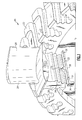
Figure 1 is an exploded view of a turbine disk and blade. -
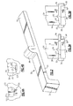
Figure 2 shows a retention device. -
Figure 3A shows a step in assembling the retention device. -
Figure 3B shows a subsequent step. -
Figure 4A is an end view. -
Figure 4B is a second cross-sectional view. - A
turbine rotor 19 is illustrated inFigure 1 having adisk 20 centered on an axis, and including a plurality ofcared slots 22. Ablade 24 has anairfoil 25, and is shown removed from theslot 22. As known,root portion 26 of theblade 24 hasears 28 that fit into theslot 22 to position theblade 24 on thedisk 20. As shown, there are a plurality ofslots 22, and ablade 24 would typically be received in eachslot 22. - A
bottom channel 27 is formed at a radially innermost end of theblade 24. Further, apositioning groove 30 is formed in a generally central location on the radially innermost end ofblade 24. - A
retainer element 32 is positioned such that anelongate body portion 33 is positioned in thechannel 27. Apositioning flange 38 is received within thegroove 30. Afirst end 34 is formed to extend radially inwardly relative to thedisk 20. Asecond end 36 is initially formed to extend straight with thebody 33. AlthoughFigure 1 depicts thegroove 30 radially extending in theroot portion 26 and theflange 38 radially extending on theretainer element 32, it will be understood that thegroove 30 can be radially extending in theretainer element 32 and theflange 38 can be radially extending on theroot portion 26. - In one embodiment, the
retainer element 32 is formed of a high temperature, high strength nickel-based alloy. Theretainer element 32 may be fabricated by unconventional machining processes such as electric discharge machining (EDM) or laser. However, other processes and materials may be utilized to form theretainer element 32. Theretainer elements 32, along with all elements in theturbine rotor 19, should be capable of providing high strength at very high temperature (e.g., 1100°F (600° C)). - As shown in
Figure 2 , theretainer element 32 has itsflange 38 at a generally central location. It should be understood thatflange 38 is not necessarily at an exact center point, but should simply be positioned somewhat centrally such that it can be received at a generally central location in the bottom of theroot 26, and in thegroove 30. To assemble theblade 24 to thedisk 20, one initially places theretainer element 32 into thegroove 30, and withbody portion 33 inchannel 27. The assembled blade and retainer may then be slid into aslot 22. - As shown in
Figure 3A , after theblade 24 is initially received in theslot 22, theend 34 abuts a first end of thedisk 20. At this time, theother end 36 extends outwardly and beyond the opposed end of thedisk 20. - As shown in
Figure 3B , theend 36 is then deformed radially inwardly, as shown at 136 in phantom inFigure 3A and as shown inFigure 3B . At that point, theretainer 32 now retains theblade 24 within theslot 22. Theflange 38 ensures theblade 24 does not move relative to the retainer, and the retainer itself cannot move relative to thedisk 20, due to theends - As can be appreciated from
Figures 3A and 3B , thechannel 27 extends between axial ends of theblade 24. Thegroove 30 is located over a small generally central portion of the radially inner end of theroot portion 26 of theblade 24. - As shown in
Figure 4A , theend 34 extends radially inwardly of thechannel 27. Thechannel 27 is positioned only at a generally circumferentially central portion of theroot 26, and there areends 127 at each circumferential side of thechannel 27. -
Figure 4B shows a generally central location, and shows that thebody portion 33 of theretainer element 32 is generally of the same thickness as a radial depth of thechannel 27. - Although an embodiment of this invention has been disclosed, a worker of ordinary skill in this art would recognize that certain modifications would come within the scope of this invention. For that reason, the following claims should be studied to determine the true scope and content of this invention.
Claims (15)
- A turbine blade assembly comprising:a turbine blade (24) having a root section (26) and an airfoil (25);said root section (26) having one of a radially extending groove (30) and flange (38); anda retainer element (32) having the other of said groove (30) and said flange (38), with said groove (30) being positioned in said flange (38) to hold said retainer element (32) and said blade (24) together, and said retainer element (32) having axial ends (34,136) which extend radially to secure an assembled blade (24) and retainer element (32) within a disk slot (22) in a turbine rotor disk (19).
- The assembly as set forth in claim 1, wherein said groove (30) extends into said root section (26) of said blade (24).
- The assembly as set forth in claim 2, wherein said groove (30) extends into said root section (26) at a radially innermost end of said root section (26).
- The assembly as set forth in claim 3, wherein a channel (27) is formed in said radially innermost end of said root section (26), and said channel (27) receives a body portion of said retainer element (32).
- The assembly as set forth in claim 2, wherein a channel (27) is formed in a radially innermost end of said root section (26), and said channel (27) receives a body portion of said retainer element (32).
- The assembly as set forth in claim 4 or 5, wherein said root section (26) extends between two axial ends, and said channel (27) extends between said two ends.
- The assembly as set forth in claim 6, wherein said groove (30) is positioned spaced between said two ends.
- The assembly as set forth in claim 6, wherein said channel (27) does not extend between circumferential sides of the root section, but instead there are circumferential ends (127) of the root section (26) defined at each of two circumferential sides of the channel (27).
- The assembly as set forth in claim 8, wherein said body portion is of the same thickness as a radial depth of said channel (27).
- The assembly as set forth in any preceding claim, wherein said retainer element (32) has a first end (34) which is formed to extend radially inwardly, and a second end (36) which is not formed to extend radially inwardly, but which is deformed radially inwardly after said assembly is positioned within a disk slot (22).
- The assembly as set forth in claim 1 wherein:said root section has said radially extending groove (30);said retainer element (32) has said radially extending flange (38);said groove (30) extends into said root section (26) of said blade (24);said groove (30) extends into said root section (26) at a radially innermost end of said root section (26);a channel (27) is formed in said radially innermost end of said root section (26), and said channel (27) receives a body portion of said retainer element (32);said root section (26) extends between two axial ends, and said channel (27) extends between said two axial ends;said channel (27) is positioned spaced between said two axial ends; andsaid retainer element (32) has a first end (34) which is formed to extend radially inwardly, and a second end (36) which is not formed to extend radially inwardly, but which is deformed radially inwardly after said assembly is positioned within a disk slot (22).
- The assembly as set forth in claim 11, wherein said channel (27) does not extend between circumferential sides of the root section (26), but instead there are circumferential ends of the root section (26) defined at each of two circumferential sides of the channel (27), and said body portion is of the same thickness as a radial depth of said channel (27).
- A method of assembling turbine blades (24) within a turbine disk (19) comprising the steps of:(a) positioning a blade (24) having one of a groove (30) and a flange (38) and a retainer element (32) having the other of a groove (30) and a flange (38) such that said flange (38) is positioned in said groove (30) to hold said blade (24) and said retainer element (32) together;(b) sliding said blade (24) and said retainer element (32) into a slot (22) in a turbine disk (19); and(c) deforming at least a portion (36) of said retainer element (32) radially to secure said retainer element (32) to said turbine disk (19), and to secure said blade (24) in said slot (22).
- The method as set forth in claim 13, wherein said retainer element (32) is formed to have two ends, and the deformation of step (c) includes deforming at least one (36) of said two ends radially inwardly.
- The method as set forth in claim 14, wherein at least one (34) of said two ends already extends radially inwardly when the positioning of step (a) occurs, and step (c) only includes deforming the other (36) of said two ends radially inwardly.
Applications Claiming Priority (1)
| Application Number | Priority Date | Filing Date | Title |
|---|---|---|---|
| US12/763,409 US8562301B2 (en) | 2010-04-20 | 2010-04-20 | Turbine blade retention device |
Publications (2)
| Publication Number | Publication Date |
|---|---|
| EP2381068A2 true EP2381068A2 (en) | 2011-10-26 |
| EP2381068A3 EP2381068A3 (en) | 2013-09-25 |
Family
ID=44080315
Family Applications (1)
| Application Number | Title | Priority Date | Filing Date |
|---|---|---|---|
| EP11162515.8A Withdrawn EP2381068A3 (en) | 2010-04-20 | 2011-04-14 | Assembly and method for assembling turbine blades |
Country Status (4)
| Country | Link |
|---|---|
| US (1) | US8562301B2 (en) |
| EP (1) | EP2381068A3 (en) |
| CN (1) | CN102235184A (en) |
| CA (1) | CA2735493C (en) |
Cited By (2)
| Publication number | Priority date | Publication date | Assignee | Title |
|---|---|---|---|---|
| CN104564801A (en) * | 2014-11-18 | 2015-04-29 | 东方电气集团东方汽轮机有限公司 | Axial positioning structure for compressor blade in impeller groove |
| WO2016162249A1 (en) * | 2015-04-08 | 2016-10-13 | Siemens Aktiengesellschaft | Turbine blade assembly arrangement and corresponding assembly tool |
Families Citing this family (9)
| Publication number | Priority date | Publication date | Assignee | Title |
|---|---|---|---|---|
| FR2963383B1 (en) * | 2010-07-27 | 2016-09-09 | Snecma | DUST OF TURBOMACHINE, ROTOR, LOW PRESSURE TURBINE AND TURBOMACHINE EQUIPPED WITH SUCH A DAWN |
| US8974188B2 (en) | 2012-03-06 | 2015-03-10 | Hamilton Sundstrand Corporation | Blade clip |
| DE102013214933A1 (en) * | 2013-07-30 | 2015-02-26 | MTU Aero Engines AG | Method for mounting a gas turbine blade in an associated receptacle of a rotor base body |
| US20150071771A1 (en) * | 2013-09-12 | 2015-03-12 | General Electric Company | Inter-stage seal for a turbomachine |
| CN104329123B (en) * | 2014-11-28 | 2015-11-11 | 哈尔滨广瀚燃气轮机有限公司 | Turbine bucket and wheel disc fixed structure |
| KR101689085B1 (en) * | 2015-08-03 | 2017-01-02 | 두산중공업 주식회사 | Assembly of the bucket with which the fixture and the bucket for a turbine blade |
| CN110296105A (en) * | 2019-08-15 | 2019-10-01 | 上海电气燃气轮机有限公司 | Blade locking mechanism |
| KR102355521B1 (en) * | 2020-08-19 | 2022-01-24 | 두산중공업 주식회사 | Assembling structure of compressor blade and gas turbine comprising the same and assembling method of compressor blade |
| FR3134601B1 (en) * | 2022-04-13 | 2026-05-08 | Safran Aircraft Engines | TOOL FOR HOLDING A BLOWER WEDGE |
Family Cites Families (21)
| Publication number | Priority date | Publication date | Assignee | Title |
|---|---|---|---|---|
| GB643914A (en) * | 1948-03-08 | 1950-09-27 | Joseph Stanley Hall | Improvements in and relating to turbine or like blade securing means |
| US2786648A (en) * | 1950-04-04 | 1957-03-26 | United Aircraft Corp | Blade locking device |
| US2847187A (en) * | 1955-01-21 | 1958-08-12 | United Aircraft Corp | Blade locking means |
| US2928651A (en) * | 1955-01-21 | 1960-03-15 | United Aircraft Corp | Blade locking means |
| US3383095A (en) * | 1967-09-12 | 1968-05-14 | Gen Electric | Lock for turbomachinery blades |
| US3720480A (en) * | 1971-06-29 | 1973-03-13 | United Aircraft Corp | Rotor construction |
| FR2344710A1 (en) * | 1976-03-16 | 1977-10-14 | Szydlowski Joseph | Blade fixture for turbine wheels - has wheel and blade roots corrugated and held together by keys and clips |
| US4236873A (en) | 1978-09-20 | 1980-12-02 | United Technologies Corporation | Wind turbine blade retention device |
| FR2603333B1 (en) | 1986-09-03 | 1990-07-20 | Snecma | TURBOMACHINE ROTOR COMPRISING A MEANS OF AXIAL LOCKING AND SEALING OF BLADES MOUNTED IN AXIAL PINS OF THE DISC AND MOUNTING METHOD |
| US4872810A (en) | 1988-12-14 | 1989-10-10 | United Technologies Corporation | Turbine rotor retention system |
| US5151013A (en) | 1990-12-27 | 1992-09-29 | United Technologies Corporation | Blade lock for a rotor disk and rotor blade assembly |
| US5173023A (en) | 1991-08-12 | 1992-12-22 | Cannon Energy Corporation | Wind turbine generator blade and retention system |
| US5261790A (en) | 1992-02-03 | 1993-11-16 | General Electric Company | Retention device for turbine blade damper |
| USH1258H (en) | 1992-09-16 | 1993-12-07 | The United States Of America As Represented By The Secretary Of The Air Force | Blade lock screw |
| US5281097A (en) | 1992-11-20 | 1994-01-25 | General Electric Company | Thermal control damper for turbine rotors |
| US5518369A (en) | 1994-12-15 | 1996-05-21 | Pratt & Whitney Canada Inc. | Gas turbine blade retention |
| GB9615826D0 (en) | 1996-07-27 | 1996-09-11 | Rolls Royce Plc | Gas turbine engine fan blade retention |
| US5984639A (en) | 1998-07-09 | 1999-11-16 | Pratt & Whitney Canada Inc. | Blade retention apparatus for gas turbine rotor |
| US6109877A (en) * | 1998-11-23 | 2000-08-29 | Pratt & Whitney Canada Corp. | Turbine blade-to-disk retention device |
| PL1703078T3 (en) * | 2005-03-17 | 2007-10-31 | Siemens Ag | Caulking device and method of caulking the locking tabs in a compressor or turbine |
| US8113784B2 (en) * | 2009-03-20 | 2012-02-14 | Hamilton Sundstrand Corporation | Coolable airfoil attachment section |
-
2010
- 2010-04-20 US US12/763,409 patent/US8562301B2/en active Active
-
2011
- 2011-03-28 CA CA2735493A patent/CA2735493C/en not_active Expired - Fee Related
- 2011-04-14 EP EP11162515.8A patent/EP2381068A3/en not_active Withdrawn
- 2011-04-20 CN CN2011100991320A patent/CN102235184A/en active Pending
Non-Patent Citations (1)
| Title |
|---|
| None |
Cited By (2)
| Publication number | Priority date | Publication date | Assignee | Title |
|---|---|---|---|---|
| CN104564801A (en) * | 2014-11-18 | 2015-04-29 | 东方电气集团东方汽轮机有限公司 | Axial positioning structure for compressor blade in impeller groove |
| WO2016162249A1 (en) * | 2015-04-08 | 2016-10-13 | Siemens Aktiengesellschaft | Turbine blade assembly arrangement and corresponding assembly tool |
Also Published As
| Publication number | Publication date |
|---|---|
| US20110255982A1 (en) | 2011-10-20 |
| CA2735493C (en) | 2014-06-03 |
| US8562301B2 (en) | 2013-10-22 |
| EP2381068A3 (en) | 2013-09-25 |
| CN102235184A (en) | 2011-11-09 |
| CA2735493A1 (en) | 2011-10-20 |
Similar Documents
| Publication | Publication Date | Title |
|---|---|---|
| US8562301B2 (en) | Turbine blade retention device | |
| KR101994511B1 (en) | Nozzle ring | |
| US9127555B2 (en) | Method for balancing rotating assembly of gas turbine engine | |
| US9328621B2 (en) | Rotor blade assembly tool for gas turbine engine | |
| EP2612998A2 (en) | Stator Vane Integrated Attachment Liner and Spring Damper | |
| EP2964894B1 (en) | Turbine segmented cover plate retention method | |
| EP2412923A2 (en) | Rotor cover plate retention | |
| EP2880278B1 (en) | Anti-rotation lug for a gas turbine engine stator assembly | |
| EP2273070B1 (en) | Method and apparatus for providing rotor discs | |
| CN107035414B (en) | Method and system for detachable blade platform retaining clips | |
| CN104364474B (en) | Stator blade diaphragm ring, turbine and method | |
| EP3009598B1 (en) | Tandem rotor blades | |
| EP3073052B1 (en) | Fan assembly | |
| CN103025480B (en) | Manufacture the method for turbogenerator drum | |
| EP2549060B1 (en) | Locking of blades in a rotor tangential mounting groove | |
| EP3244014A2 (en) | Retaining ring | |
| EP2977547A1 (en) | Rotor blade dovetail with rounded bearing surfaces | |
| EP3647545A1 (en) | Turbine blade assembly, corresponding gas turbine engine and corresponding methode of securing a turbine blade | |
| EP3647541A1 (en) | Split vernier ring for turbine rotor stack assembly | |
| US20140169975A1 (en) | Rotor blade root spacer with a fracture feature | |
| EP2946080B1 (en) | Rotor blade root spacer with grip element | |
| EP3851634A1 (en) | Seal element for sealing a joint between a rotor blade and a rotor disk of a turbine engine | |
| EP3303773B1 (en) | Attachment system for a turbine airfoil usable in a gas turbine engine | |
| US10954885B2 (en) | Flow guiding device and method for forming a flow guiding device | |
| US11525363B2 (en) | Turbine wheel and wire retention pin fixation method for turbine wheel |
Legal Events
| Date | Code | Title | Description |
|---|---|---|---|
| AK | Designated contracting states |
Kind code of ref document: A2 Designated state(s): AL AT BE BG CH CY CZ DE DK EE ES FI FR GB GR HR HU IE IS IT LI LT LU LV MC MK MT NL NO PL PT RO RS SE SI SK SM TR |
|
| AX | Request for extension of the european patent |
Extension state: BA ME |
|
| PUAI | Public reference made under article 153(3) epc to a published international application that has entered the european phase |
Free format text: ORIGINAL CODE: 0009012 |
|
| PUAL | Search report despatched |
Free format text: ORIGINAL CODE: 0009013 |
|
| AK | Designated contracting states |
Kind code of ref document: A3 Designated state(s): AL AT BE BG CH CY CZ DE DK EE ES FI FR GB GR HR HU IE IS IT LI LT LU LV MC MK MT NL NO PL PT RO RS SE SI SK SM TR |
|
| AX | Request for extension of the european patent |
Extension state: BA ME |
|
| RIC1 | Information provided on ipc code assigned before grant |
Ipc: F01D 5/30 20060101AFI20130821BHEP |
|
| 17P | Request for examination filed |
Effective date: 20131223 |
|
| RBV | Designated contracting states (corrected) |
Designated state(s): AL AT BE BG CH CY CZ DE DK EE ES FI FR GB GR HR HU IE IS IT LI LT LU LV MC MK MT NL NO PL PT RO RS SE SI SK SM TR |
|
| STAA | Information on the status of an ep patent application or granted ep patent |
Free format text: STATUS: EXAMINATION IS IN PROGRESS |
|
| 17Q | First examination report despatched |
Effective date: 20180221 |
|
| GRAP | Despatch of communication of intention to grant a patent |
Free format text: ORIGINAL CODE: EPIDOSNIGR1 |
|
| STAA | Information on the status of an ep patent application or granted ep patent |
Free format text: STATUS: GRANT OF PATENT IS INTENDED |
|
| INTG | Intention to grant announced |
Effective date: 20200304 |
|
| STAA | Information on the status of an ep patent application or granted ep patent |
Free format text: STATUS: THE APPLICATION IS DEEMED TO BE WITHDRAWN |
|
| 18D | Application deemed to be withdrawn |
Effective date: 20200715 |