EP2380792B1 - Brake-by-wire system - Google Patents
Brake-by-wire system Download PDFInfo
- Publication number
- EP2380792B1 EP2380792B1 EP11170035.7A EP11170035A EP2380792B1 EP 2380792 B1 EP2380792 B1 EP 2380792B1 EP 11170035 A EP11170035 A EP 11170035A EP 2380792 B1 EP2380792 B1 EP 2380792B1
- Authority
- EP
- European Patent Office
- Prior art keywords
- port
- valve member
- valve
- blocked
- communicated
- Prior art date
- Legal status (The legal status is an assumption and is not a legal conclusion. Google has not performed a legal analysis and makes no representation as to the accuracy of the status listed.)
- Active
Links
- 239000012530 fluid Substances 0.000 claims description 13
- 230000001276 controlling effect Effects 0.000 description 2
- 238000010586 diagram Methods 0.000 description 1
- 238000012986 modification Methods 0.000 description 1
- 230000004048 modification Effects 0.000 description 1
- 230000001105 regulatory effect Effects 0.000 description 1
Images
Classifications
-
- B—PERFORMING OPERATIONS; TRANSPORTING
- B60—VEHICLES IN GENERAL
- B60T—VEHICLE BRAKE CONTROL SYSTEMS OR PARTS THEREOF; BRAKE CONTROL SYSTEMS OR PARTS THEREOF, IN GENERAL; ARRANGEMENT OF BRAKING ELEMENTS ON VEHICLES IN GENERAL; PORTABLE DEVICES FOR PREVENTING UNWANTED MOVEMENT OF VEHICLES; VEHICLE MODIFICATIONS TO FACILITATE COOLING OF BRAKES
- B60T8/00—Arrangements for adjusting wheel-braking force to meet varying vehicular or ground-surface conditions, e.g. limiting or varying distribution of braking force
- B60T8/32—Arrangements for adjusting wheel-braking force to meet varying vehicular or ground-surface conditions, e.g. limiting or varying distribution of braking force responsive to a speed condition, e.g. acceleration or deceleration
- B60T8/321—Arrangements for adjusting wheel-braking force to meet varying vehicular or ground-surface conditions, e.g. limiting or varying distribution of braking force responsive to a speed condition, e.g. acceleration or deceleration deceleration
- B60T8/3255—Systems in which the braking action is dependent on brake pedal data
- B60T8/327—Pneumatic systems
-
- B—PERFORMING OPERATIONS; TRANSPORTING
- B60—VEHICLES IN GENERAL
- B60T—VEHICLE BRAKE CONTROL SYSTEMS OR PARTS THEREOF; BRAKE CONTROL SYSTEMS OR PARTS THEREOF, IN GENERAL; ARRANGEMENT OF BRAKING ELEMENTS ON VEHICLES IN GENERAL; PORTABLE DEVICES FOR PREVENTING UNWANTED MOVEMENT OF VEHICLES; VEHICLE MODIFICATIONS TO FACILITATE COOLING OF BRAKES
- B60T13/00—Transmitting braking action from initiating means to ultimate brake actuator with power assistance or drive; Brake systems incorporating such transmitting means, e.g. air-pressure brake systems
- B60T13/10—Transmitting braking action from initiating means to ultimate brake actuator with power assistance or drive; Brake systems incorporating such transmitting means, e.g. air-pressure brake systems with fluid assistance, drive, or release
- B60T13/66—Electrical control in fluid-pressure brake systems
- B60T13/68—Electrical control in fluid-pressure brake systems by electrically-controlled valves
- B60T13/683—Electrical control in fluid-pressure brake systems by electrically-controlled valves in pneumatic systems or parts thereof
-
- B—PERFORMING OPERATIONS; TRANSPORTING
- B60—VEHICLES IN GENERAL
- B60T—VEHICLE BRAKE CONTROL SYSTEMS OR PARTS THEREOF; BRAKE CONTROL SYSTEMS OR PARTS THEREOF, IN GENERAL; ARRANGEMENT OF BRAKING ELEMENTS ON VEHICLES IN GENERAL; PORTABLE DEVICES FOR PREVENTING UNWANTED MOVEMENT OF VEHICLES; VEHICLE MODIFICATIONS TO FACILITATE COOLING OF BRAKES
- B60T7/00—Brake-action initiating means
- B60T7/12—Brake-action initiating means for automatic initiation; for initiation not subject to will of driver or passenger
- B60T7/20—Brake-action initiating means for automatic initiation; for initiation not subject to will of driver or passenger specially for trailers, e.g. in case of uncoupling of or overrunning by trailer
-
- B—PERFORMING OPERATIONS; TRANSPORTING
- B60—VEHICLES IN GENERAL
- B60T—VEHICLE BRAKE CONTROL SYSTEMS OR PARTS THEREOF; BRAKE CONTROL SYSTEMS OR PARTS THEREOF, IN GENERAL; ARRANGEMENT OF BRAKING ELEMENTS ON VEHICLES IN GENERAL; PORTABLE DEVICES FOR PREVENTING UNWANTED MOVEMENT OF VEHICLES; VEHICLE MODIFICATIONS TO FACILITATE COOLING OF BRAKES
- B60T8/00—Arrangements for adjusting wheel-braking force to meet varying vehicular or ground-surface conditions, e.g. limiting or varying distribution of braking force
- B60T8/32—Arrangements for adjusting wheel-braking force to meet varying vehicular or ground-surface conditions, e.g. limiting or varying distribution of braking force responsive to a speed condition, e.g. acceleration or deceleration
- B60T8/321—Arrangements for adjusting wheel-braking force to meet varying vehicular or ground-surface conditions, e.g. limiting or varying distribution of braking force responsive to a speed condition, e.g. acceleration or deceleration deceleration
- B60T8/323—Systems specially adapted for tractor-trailer combinations
-
- B—PERFORMING OPERATIONS; TRANSPORTING
- B60—VEHICLES IN GENERAL
- B60T—VEHICLE BRAKE CONTROL SYSTEMS OR PARTS THEREOF; BRAKE CONTROL SYSTEMS OR PARTS THEREOF, IN GENERAL; ARRANGEMENT OF BRAKING ELEMENTS ON VEHICLES IN GENERAL; PORTABLE DEVICES FOR PREVENTING UNWANTED MOVEMENT OF VEHICLES; VEHICLE MODIFICATIONS TO FACILITATE COOLING OF BRAKES
- B60T8/00—Arrangements for adjusting wheel-braking force to meet varying vehicular or ground-surface conditions, e.g. limiting or varying distribution of braking force
- B60T8/32—Arrangements for adjusting wheel-braking force to meet varying vehicular or ground-surface conditions, e.g. limiting or varying distribution of braking force responsive to a speed condition, e.g. acceleration or deceleration
- B60T8/34—Arrangements for adjusting wheel-braking force to meet varying vehicular or ground-surface conditions, e.g. limiting or varying distribution of braking force responsive to a speed condition, e.g. acceleration or deceleration having a fluid pressure regulator responsive to a speed condition
- B60T8/36—Arrangements for adjusting wheel-braking force to meet varying vehicular or ground-surface conditions, e.g. limiting or varying distribution of braking force responsive to a speed condition, e.g. acceleration or deceleration having a fluid pressure regulator responsive to a speed condition including a pilot valve responding to an electromagnetic force
- B60T8/3615—Electromagnetic valves specially adapted for anti-lock brake and traction control systems
- B60T8/3655—Continuously controlled electromagnetic valves
Definitions
- the present invention relates to a brake-by-wire system including a trailer brake control circuit, comprising a fluid pressure source and a fluid reservoir, wherein the fluid pressure source comprises a tank of pressurized air and the fluid reservoir comprises an air vent.
- a by-wire brake system at least some of the traditional components such as the pumps, hoses, fluids, belts and brake boosters and master cylinders are replaced with electronic sensors and actuators.
- an object of this invention is to provide an electro-pneumatic by-wire trailer brake system which can function even if one of the internal components fails.
- a brake control circuit of the above mentioned type comprises a brake-by-wire system including a trailer brake control circuit, comprising a fluid pressure source and a fluid reservoir, wherein the fluid pressure source comprises a tank of pressurized air and the fluid reservoir, comprises an air vent, comprising a first and a second electro-pneumatic solenoid operated proportional valve parallel arranged to each other, for controlling communication between the source, the reservoir and trailer brakes, wherein the trailer brakes comprise a service trailer brake and a trailer park brake, and further with a first and second solenoid operated pneumatic shutoff valve, each controlling communication between one of the trailer brakes and a corresponding one of the proportional valves, wherein the first solenoid operated proportional valve has a first port connected to the tank, a second port connected to the vent, a third port, a first valve member movable to a first position wherein the first port is blocked and the second port is communicated with the third port, and movable to a second position wherein the second port is blocked and
- the valves control communication between a pressure source, a reservoir and the trailer brakes.
- Each shutoff valve is between a trailer service or park brake and a corresponding one of the proportional valves.
- the system includes four electro-pneumatic valves.
- the system includes a pair of valves on each side of the circuit.
- Each side of the circuit includes a proportional valve to achieve the trailer braking function and a shutoff valve to stop the proportional valve from working unintentionally.
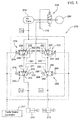
- Fig. 1 is a schematic diagram of a brake-by-wire system of the present invention for pneumatic trailer brakes and spring park brakes.
- a brake control circuit 210 is installed as part of a by-wire brake system (not shown) on a vehicle (not shown) such as a tractor, and is connected to an electronic trailer brake controller 211 and to pneumatic trailer service brakes 212 and pneumatic spring trailer park brakes 213 on a trailer (not shown).
- Brake control circuit 210 includes four solenoid operated valves 218, 220, 222 and 224, and is connected to a tank 214 or source of pressurized air and an air vent 216.
- a regulating valve 208 regulates the pressure in tank 214 supplied by air compressor 206.
- First solenoid operated proportional valve 218 has a first port 230 connected to the tank 214, a second port 232 connected to the vent 216, and a third port 234.
- Valve 218 also includes a first valve member 240 movable to a first position wherein the first port 230 is blocked and the second port 232 is communicated with the third port 234.
- Valve member 240 is also movable to a second position wherein the second port 232 is blocked and the first port 230 is communicated with the third port 234.
- a spring 242 biases the first valve member 240 to its first position.
- a solenoid 244 is operable to move the first valve member 240 to its second position.
- Second solenoid operated proportional valve 220 has a first port 250 connected to the source 214, a second port 252 connected to the reservoir 216, and a third port 254.
- a second valve member 260 is movable to a first position wherein the first port 250 is blocked and the second port 252 is communicated with the third port 254.
- Valve member 260 is also movable to a second position wherein the second port 252 is blocked and the first port 250 is communicated with the third port 254.
- a spring 262 biases the second valve member 260 to its first position.
- a solenoid 264 is operable to move the second valve member 260 to its second position.
- First solenoid operated shutoff valve 222 has a first port 270 connected to the third port 234 of the first valve 218, a second port 271 connected to the vent 216 and a third port 272 connected to the pneumatic trailer service brake 212.
- Valve 222 has a third valve member 274 movable to a first position wherein the first port 270 is blocked and second port 271 is communicated to third port 272, and movable to a second position wherein the second port 271 is blocked and port 270 is communicated with the second port 272.
- a spring 276 biases the third valve member 274 to its first position.
- a solenoid 278 is operable to move the third valve member 274 to its second position.
- Second solenoid operated shutoff valve 224 has a first port 280 connected to the third port 254 of the second valve 220, a second port 281 connected to the vent 216 and a third port 282 connected to the trailer spring-applied park brake 213.
- Valve 222 has a third valve member 284 movable to a first position wherein the first port 280 is blocked and second port 281 is communicated to third port 282, and movable to a second position wherein the second port 281 is blocked and port 280 is communicated with the third port 282.
- a spring 286 biases the third valve member 284 to its first position.
- a solenoid 288 is operable to move the third valve member 284 to its second position.
- the circuit 210 also includes a first pilot line 290 which communicates the third port 234 of the first valve to an end of the first valve member 240.
- a second pilot line 292 communicates the third port 254 of the second valve 220 to an end of the second valve member 260.
- the circuit 210 includes four valves to provide redundancy to ensure brake function in the event of a single valve failure.
- the system includes redundancy on each side, with each side having a proportional valve to achieve the trailer braking function and a shut off valve to stop the proportional valve from working unintentionally.
- the two proportional valves can be used to achieve the braking function either individually or in conjunction with one another.
- the shut off valves are used to shut off one of the proportional valves if it is malfunctioning or to prevent back flow when only one valve is used.
Description
- The present invention relates to a brake-by-wire system including a trailer brake control circuit, comprising a fluid pressure source and a fluid reservoir, wherein the fluid pressure source comprises a tank of pressurized air and the fluid reservoir comprises an air vent.
- In a by-wire brake system at least some of the traditional components such as the pumps, hoses, fluids, belts and brake boosters and master cylinders are replaced with electronic sensors and actuators.
- There is a need for redundant electro-pneumatic control circuits for trailer brakes in a by-wire brake system. The circuits must be capable of functioning even if one of the internal components fail, while at the same time, still achieving all of the requirements for a hydraulic or pneumatic trailer brake system.
- Accordingly, an object of this invention is to provide an electro-pneumatic by-wire trailer brake system which can function even if one of the internal components fails.
- The object of the invention will be achieved by the teachings of claim 1.
- According to the invention a brake control circuit of the above mentioned type comprises a brake-by-wire system including a trailer brake control circuit, comprising a fluid pressure source and a fluid reservoir, wherein the fluid pressure source comprises a tank of pressurized air and the fluid reservoir, comprises an air vent, comprising a first and a second electro-pneumatic solenoid operated proportional valve parallel arranged to each other, for controlling communication between the source, the reservoir and trailer brakes, wherein the trailer brakes comprise a service trailer brake and a trailer park brake, and further with a first and second solenoid operated pneumatic shutoff valve, each controlling communication between one of the trailer brakes and a corresponding one of the proportional valves, wherein the first solenoid operated proportional valve has a first port connected to the tank, a second port connected to the vent, a third port, a first valve member movable to a first position wherein the first port is blocked and the second port is communicated with the third port, and movable to a second position wherein the second port is blocked and the first port is communicated with the third port, a spring biasing the first valve member to its first position, and a solenoid operable to move the first valve member to its second position; the second solenoid operated proportional valve has a first port connected to the tank, a second port connected to the vent, a third port, a second valve member movable to a first position wherein the first port is blocked and the second port is communicated with the third port, and movable to a second position wherein the second port is blocked and the first port is communicated with the third port, a spring biasing the second valve member to its first position, and a solenoid operable to move the second valve member to its second position; the first solenoid operated shutoff valve has a first port connected to the third port of the first solenoid operated proportional valve, a second port connected to the vent, a third port connected to the trailer service brake, a third valve member movable to a first position wherein the first port is blocked and the second port is communicated to the third port, and movable to a second position wherein the second port is blocked and the first port is communicated with the third port, a spring biasing the third valve member to its first position, and a solenoid operable to move the third valve member to its second position; and the second solenoid operated shutoff valve has a first port connected to the third port of the second solenoid operated proportional valve, a second port connected to the vent, a third port connected to the trailer park brake, a third valve member movable to a first position wherein the first port is blocked and the second port is communicated to the third port, and movable to a second position wherein the second port is blocked and the first port is communicated with the third port, a spring biasing the third valve member to its first position, and a solenoid operable to move the third valve member to its second position. The valves control communication between a pressure source, a reservoir and the trailer brakes. Each shutoff valve is between a trailer service or park brake and a corresponding one of the proportional valves. Thus, the system includes four electro-pneumatic valves. The system includes a pair of valves on each side of the circuit. Each side of the circuit includes a proportional valve to achieve the trailer braking function and a shutoff valve to stop the proportional valve from working unintentionally.
-
Fig. 1 is a schematic diagram of a brake-by-wire system of the present invention for pneumatic trailer brakes and spring park brakes. - Referring now to
Fig. 1 , abrake control circuit 210 is installed as part of a by-wire brake system (not shown) on a vehicle (not shown) such as a tractor, and is connected to an electronictrailer brake controller 211 and to pneumatictrailer service brakes 212 and pneumatic springtrailer park brakes 213 on a trailer (not shown).Brake control circuit 210 includes four solenoid operatedvalves tank 214 or source of pressurized air and anair vent 216. A regulatingvalve 208 regulates the pressure intank 214 supplied byair compressor 206. - First solenoid operated
proportional valve 218 has afirst port 230 connected to thetank 214, asecond port 232 connected to thevent 216, and athird port 234. Valve 218 also includes afirst valve member 240 movable to a first position wherein thefirst port 230 is blocked and thesecond port 232 is communicated with thethird port 234. Valvemember 240 is also movable to a second position wherein thesecond port 232 is blocked and thefirst port 230 is communicated with thethird port 234. A spring 242 biases thefirst valve member 240 to its first position. Asolenoid 244 is operable to move thefirst valve member 240 to its second position. - Second solenoid operated
proportional valve 220 has afirst port 250 connected to thesource 214, asecond port 252 connected to thereservoir 216, and athird port 254. Asecond valve member 260 is movable to a first position wherein thefirst port 250 is blocked and thesecond port 252 is communicated with thethird port 254. Valvemember 260 is also movable to a second position wherein thesecond port 252 is blocked and thefirst port 250 is communicated with thethird port 254. A spring 262 biases thesecond valve member 260 to its first position. Asolenoid 264 is operable to move thesecond valve member 260 to its second position. - First solenoid operated
shutoff valve 222 has afirst port 270 connected to thethird port 234 of thefirst valve 218, asecond port 271 connected to thevent 216 and athird port 272 connected to the pneumatictrailer service brake 212. Valve 222 has athird valve member 274 movable to a first position wherein thefirst port 270 is blocked andsecond port 271 is communicated tothird port 272, and movable to a second position wherein thesecond port 271 is blocked andport 270 is communicated with thesecond port 272. Aspring 276 biases thethird valve member 274 to its first position. Asolenoid 278 is operable to move thethird valve member 274 to its second position. - Second solenoid operated
shutoff valve 224 has afirst port 280 connected to thethird port 254 of thesecond valve 220, asecond port 281 connected to thevent 216 and athird port 282 connected to the trailer spring-appliedpark brake 213. Valve 222 has athird valve member 284 movable to a first position wherein thefirst port 280 is blocked andsecond port 281 is communicated tothird port 282, and movable to a second position wherein thesecond port 281 is blocked andport 280 is communicated with thethird port 282. Aspring 286 biases thethird valve member 284 to its first position. Asolenoid 288 is operable to move thethird valve member 284 to its second position. - The
circuit 210 also includes afirst pilot line 290 which communicates thethird port 234 of the first valve to an end of thefirst valve member 240. Asecond pilot line 292 communicates thethird port 254 of thesecond valve 220 to an end of thesecond valve member 260. - With this
circuit 210 thetrailer brakes - While the present invention has been described in conjunction with a specific embodiment, it is understood that many alternatives, modifications and variations will be apparent to those skilled in the art in light of the foregoing description.
Claims (1)
- A brake-by-wire system including a trailer brake control circuit (210), comprising a fluid pressure source (214) and a fluid reservoir (216), wherein the fluid pressure source (214) comprises a tank of pressurized air and the fluid reservoir (216) comprises an air vent, comprising a first and a second electro-pneumatic solenoid operated proportional valve (218, 220) parallel arranged to each other, for controlling communication between the source (214), the reservoir (216) and trailer brakes (212, 213), wherein the trailer brakes (212, 213) comprise a service trailer brake (212) and a trailer park brake (213), and further with a first and second solenoid operated pneumatic shutoff valve (222, 224), each controlling communication between one of the trailer brakes (212, 213) and a corresponding one of the proportional valves (218, 220), wherein the first solenoid operated proportional valve (218) has a first port (230) connected to the tank (214), a second port (232) connected to the vent (216), a third port (234), a first valve member (240) movable to a first position wherein the first port (230) is blocked and the second port (232) is communicated with the third port (234), and movable to a second position wherein the second port (232) is blocked and the first port (230) is communicated with the third port (234), a spring (242) biasing the first valve member (240) to its first position, and a solenoid (244) operable to move the first valve member (240) to its second position; the second solenoid operated proportional valve (220) has a first port (250) connected to the tank (214), a second port (252) connected to the vent (216), a third port (254), a second valve member (260) movable to a first position wherein the first port (250) is blocked and the second port (252) is communicated with the third port (254), and movable to a second position wherein the second port (252) is blocked and the first port (250) is communicated with the third port (254), a spring (262) biasing the second valve member (260) to its first position, and a solenoid (264) operable to move the second valve member (260) to its second position; the first solenoid operated shutoff valve (222) has a first port (270) connected to the third port (234) of the first solenoid operated proportional valve (218), a second port (271) connected to the vent (216), a third port (272) connected to the trailer service brake (212), a third valve member (274) movable to a first position wherein the first port (270) is blocked and the second port (271) is communicated to the third port (272), and movable to a second position wherein the second port (271) is blocked and the first port (270) is communicated with the third port (272), a spring (276) biasing the third valve member (274) to its first position, and a solenoid (278) operable to move the third valve member (274) to its second position; and the second solenoid operated shutoff valve (224) has a first port (280) connected to the third port (254) of the second solenoid operated proportional valve (220), a second port (282) connected to the vent (216), a third port (282) connected to the trailer park brake (213), a third valve member (284) movable to a first position wherein the first port (280) is blocked and the second port (281) is communicated to the third port (282), and movable to a second position wherein the second port (281) is blocked and the first port (280) is communicated with the third port (282), a spring (286) biasing the third valve member (284) to its first position, and a solenoid (288) operable to move the third valve member (284) to its second position.
Applications Claiming Priority (2)
| Application Number | Priority Date | Filing Date | Title |
|---|---|---|---|
| US11/951,067 US7517026B1 (en) | 2007-12-05 | 2007-12-05 | Control circuit for trailer brakes in a by-wire brake system |
| EP08170233.4A EP2067675B1 (en) | 2007-12-05 | 2008-11-28 | Brake control circuit |
Related Parent Applications (1)
| Application Number | Title | Priority Date | Filing Date |
|---|---|---|---|
| EP08170233.4 Division | 2008-11-28 |
Publications (2)
| Publication Number | Publication Date |
|---|---|
| EP2380792A1 EP2380792A1 (en) | 2011-10-26 |
| EP2380792B1 true EP2380792B1 (en) | 2013-12-11 |
Family
ID=40365405
Family Applications (2)
| Application Number | Title | Priority Date | Filing Date |
|---|---|---|---|
| EP08170233.4A Active EP2067675B1 (en) | 2007-12-05 | 2008-11-28 | Brake control circuit |
| EP11170035.7A Active EP2380792B1 (en) | 2007-12-05 | 2008-11-28 | Brake-by-wire system |
Family Applications Before (1)
| Application Number | Title | Priority Date | Filing Date |
|---|---|---|---|
| EP08170233.4A Active EP2067675B1 (en) | 2007-12-05 | 2008-11-28 | Brake control circuit |
Country Status (2)
| Country | Link |
|---|---|
| US (1) | US7517026B1 (en) |
| EP (2) | EP2067675B1 (en) |
Families Citing this family (15)
| Publication number | Priority date | Publication date | Assignee | Title |
|---|---|---|---|---|
| FR2897581B1 (en) * | 2006-02-22 | 2008-05-16 | Poclain Hydraulics Ind Soc Par | DEVICE FOR CONTROLLING THE HYDRAULIC BRAKE OF A TRAILER ATTACHED TO A TRACTOR |
| ITBO20060714A1 (en) * | 2006-10-16 | 2008-04-17 | Cnh Italia Spa | PARKING BRAKE, IN PARTICULAR FOR AN AGRICULTURAL TRACTOR, EQUIPPED WITH A SAFETY DEVICE |
| DE202008008044U1 (en) * | 2008-06-16 | 2009-11-05 | Liebherr-Hydraulikbagger Gmbh | Mobile working device |
| PL216956B1 (en) * | 2010-04-14 | 2014-05-30 | Przemysłowy Inst Masz Rolniczych | Electro-pneumatic system for controlling the pneumatic-hydraulic operation system and hydraulic brakes, especially light and medium-size trailers and semitrailers |
| US9802593B2 (en) * | 2011-06-07 | 2017-10-31 | Bendix Commercial Vehicle Systems Llc | Multi-pressure valve controller and method for a vehicle braking system |
| US8974011B2 (en) * | 2012-10-23 | 2015-03-10 | Deere & Company | Tractor hydraulic brake circuit with ABS capability |
| DE102012023137A1 (en) * | 2012-11-27 | 2014-05-28 | Wabco Gmbh | Valve arrangement for an electropneumatic brake system |
| DE102013012538A1 (en) * | 2013-07-27 | 2015-01-29 | Borgwarner Inc. | Hydraulic control device for controlling a double clutch and method for the hydraulic control of a dual clutch |
| US9434366B1 (en) * | 2015-04-09 | 2016-09-06 | Bendix Commercial Vehicle Systems Llc | Parking apparatus for a heavy vehicle during a loss of electrical power |
| DE102016100526A1 (en) * | 2016-01-14 | 2017-07-20 | Knorr-Bremse Systeme für Nutzfahrzeuge GmbH | Control device for controlling a brake system for a vehicle, brake system for a vehicle, method for operating a control device and method for applying at least one braking device of a brake system for a vehicle with a brake pressure |
| US10173652B2 (en) * | 2016-07-28 | 2019-01-08 | Deere & Company | Hydraulic trailer brake circuit for adjustable gain and improved stability |
| US10040436B2 (en) * | 2016-07-28 | 2018-08-07 | Deere & Company | Trailer brake pilot control circuit and method of control thereof |
| DE102017005980A1 (en) * | 2017-03-21 | 2018-09-27 | Wabco Gmbh | Integrated trailer control module (TCV) with external electropneumatic manual brake unit (EPH) |
| US11820341B2 (en) * | 2020-10-01 | 2023-11-21 | Valcrum, Llc | Electrically modulated air brake |
| US11932213B2 (en) * | 2021-03-26 | 2024-03-19 | Toyota Research Institute, Inc. | System and method for controlling one or more brakes of a vehicle |
Family Cites Families (15)
| Publication number | Priority date | Publication date | Assignee | Title |
|---|---|---|---|---|
| DE3215475A1 (en) | 1982-04-24 | 1983-11-03 | Robert Bosch Gmbh, 7000 Stuttgart | ELECTRO-PNEUMATIC BRAKE SYSTEM |
| US4835970A (en) * | 1985-08-13 | 1989-06-06 | Nissan Motor Co. Ltd. | Pneumatic power brake system |
| JPS6361671A (en) * | 1986-08-30 | 1988-03-17 | Sumitomo Electric Ind Ltd | Control device for brake pressure |
| US5018797A (en) * | 1988-11-14 | 1991-05-28 | Sumitomo Electric Industries, Ltd. | Fluid pressure controller |
| GB9102472D0 (en) * | 1991-02-05 | 1991-03-20 | Lucas Ind Plc | Braking system for a vehicle |
| GB9215510D0 (en) * | 1992-07-22 | 1992-09-02 | Grau Ltd | Braking systems |
| JP3261225B2 (en) * | 1993-09-16 | 2002-02-25 | 本田技研工業株式会社 | Vehicle braking system |
| US5941608A (en) * | 1996-03-07 | 1999-08-24 | Kelsey-Hayes Company | Electronic brake management system with manual fail safe |
| JP3753810B2 (en) * | 1996-10-18 | 2006-03-08 | 株式会社日立製作所 | Brake hydraulic pressure control device |
| DE19718533A1 (en) * | 1997-05-02 | 1998-11-05 | Itt Mfg Enterprises Inc | Brake control system for vehicle |
| DE10018400C1 (en) * | 2000-04-13 | 2001-08-30 | Haldex Brake Prod Gmbh | Valve arrangement for compressed air braking system has multiple identical parallel valves driven selectively individually or in common for large throughputs according to control philosophy |
| US6666527B2 (en) * | 2001-06-04 | 2003-12-23 | Dura Global Technologies Inc. | Electro-hydraulic brake actuating device for a trailer |
| US7128376B2 (en) | 2003-05-30 | 2006-10-31 | Goodrich Corporation | Redundant architecture for brake-by-wire system |
| US7150508B2 (en) * | 2004-04-19 | 2006-12-19 | Kelsey-Hayes Company | Modular regenerative braking |
| DE102004035763A1 (en) * | 2004-07-21 | 2006-03-16 | Wabco Gmbh & Co.Ohg | Brake pressure modulator pilot unit |
-
2007
- 2007-12-05 US US11/951,067 patent/US7517026B1/en active Active
-
2008
- 2008-11-28 EP EP08170233.4A patent/EP2067675B1/en active Active
- 2008-11-28 EP EP11170035.7A patent/EP2380792B1/en active Active
Also Published As
| Publication number | Publication date |
|---|---|
| EP2067675A3 (en) | 2010-12-01 |
| EP2067675A2 (en) | 2009-06-10 |
| EP2380792A1 (en) | 2011-10-26 |
| EP2067675B1 (en) | 2013-12-11 |
| US7517026B1 (en) | 2009-04-14 |
Similar Documents
| Publication | Publication Date | Title |
|---|---|---|
| EP2380792B1 (en) | Brake-by-wire system | |
| US10093293B2 (en) | Brake pressure modulator of an electronic braking system of a utility vehicle | |
| EP2794368B1 (en) | Electronically controlled pneumatic brake system for an automotive vehicle and automotive vehicle equipped with such a system | |
| US20100025141A1 (en) | Electro-Pneumatic Brake Control Device | |
| EP2750945B1 (en) | Vehicle braking system | |
| CN112867648B (en) | Redundant module of pneumatic brake system, pneumatic brake system and vehicle | |
| CN114650938B (en) | Electronic pneumatic control module | |
| US11661040B2 (en) | Braking system | |
| US20220048488A1 (en) | Secondary brake system of a vehicle, and method for controlling it | |
| EP2008897A2 (en) | Hydraulic by-wire vehicle braking system | |
| US8777332B2 (en) | Braking control system | |
| US20200290585A1 (en) | By-pass of air supply protection for electronic parking brake system and vehicle comprising such system | |
| US11738730B2 (en) | Vehicle braking system | |
| CN112088115B (en) | Redundant brake unit for a brake system and system using the same | |
| GB2417764A (en) | Trailer park brake | |
| CN114761295A (en) | Anti-failure valve unit for parking brake function and parking brake valve facility | |
| CN112512881A (en) | Electro-pneumatic handbrake (EPH) with partially decoupled TCV (European drive control) | |
| US20240116484A1 (en) | Vehicle control device | |
| JP7416907B2 (en) | parking brake device | |
| US20230264669A1 (en) | Electropneumatic device with a protective valve unit | |
| CN117693454A (en) | Electronically controllable pneumatic brake system with failsafe brake application for autopilot operation with only one shuttle valve | |
| CN117677549A (en) | Safety parking brake valve unit with bypass valve |
Legal Events
| Date | Code | Title | Description |
|---|---|---|---|
| AC | Divisional application: reference to earlier application |
Ref document number: 2067675 Country of ref document: EP Kind code of ref document: P |
|
| AK | Designated contracting states |
Kind code of ref document: A1 Designated state(s): AT BE BG CH CY CZ DE DK EE ES FI FR GB GR HR HU IE IS IT LI LT LU LV MC MT NL NO PL PT RO SE SI SK TR |
|
| AX | Request for extension of the european patent |
Extension state: AL BA MK RS |
|
| PUAI | Public reference made under article 153(3) epc to a published international application that has entered the european phase |
Free format text: ORIGINAL CODE: 0009012 |
|
| 17P | Request for examination filed |
Effective date: 20120426 |
|
| GRAP | Despatch of communication of intention to grant a patent |
Free format text: ORIGINAL CODE: EPIDOSNIGR1 |
|
| RIC1 | Information provided on ipc code assigned before grant |
Ipc: B60T 8/32 20060101ALN20130527BHEP Ipc: B60T 7/20 20060101ALI20130527BHEP Ipc: B60T 13/68 20060101AFI20130527BHEP |
|
| INTG | Intention to grant announced |
Effective date: 20130703 |
|
| GRAS | Grant fee paid |
Free format text: ORIGINAL CODE: EPIDOSNIGR3 |
|
| GRAA | (expected) grant |
Free format text: ORIGINAL CODE: 0009210 |
|
| AC | Divisional application: reference to earlier application |
Ref document number: 2067675 Country of ref document: EP Kind code of ref document: P |
|
| AK | Designated contracting states |
Kind code of ref document: B1 Designated state(s): AT BE BG CH CY CZ DE DK EE ES FI FR GB GR HR HU IE IS IT LI LT LU LV MC MT NL NO PL PT RO SE SI SK TR |
|
| REG | Reference to a national code |
Ref country code: GB Ref legal event code: FG4D |
|
| REG | Reference to a national code |
Ref country code: CH Ref legal event code: EP |
|
| REG | Reference to a national code |
Ref country code: AT Ref legal event code: REF Ref document number: 644365 Country of ref document: AT Kind code of ref document: T Effective date: 20140115 |
|
| REG | Reference to a national code |
Ref country code: IE Ref legal event code: FG4D |
|
| REG | Reference to a national code |
Ref country code: DE Ref legal event code: R096 Ref document number: 602008029337 Country of ref document: DE Effective date: 20140206 |
|
| REG | Reference to a national code |
Ref country code: NL Ref legal event code: VDEP Effective date: 20131211 |
|
| REG | Reference to a national code |
Ref country code: AT Ref legal event code: MK05 Ref document number: 644365 Country of ref document: AT Kind code of ref document: T Effective date: 20131211 |
|
| PG25 | Lapsed in a contracting state [announced via postgrant information from national office to epo] |
Ref country code: NL Free format text: LAPSE BECAUSE OF FAILURE TO SUBMIT A TRANSLATION OF THE DESCRIPTION OR TO PAY THE FEE WITHIN THE PRESCRIBED TIME-LIMIT Effective date: 20131211 Ref country code: FI Free format text: LAPSE BECAUSE OF FAILURE TO SUBMIT A TRANSLATION OF THE DESCRIPTION OR TO PAY THE FEE WITHIN THE PRESCRIBED TIME-LIMIT Effective date: 20131211 Ref country code: HR Free format text: LAPSE BECAUSE OF FAILURE TO SUBMIT A TRANSLATION OF THE DESCRIPTION OR TO PAY THE FEE WITHIN THE PRESCRIBED TIME-LIMIT Effective date: 20131211 Ref country code: SE Free format text: LAPSE BECAUSE OF FAILURE TO SUBMIT A TRANSLATION OF THE DESCRIPTION OR TO PAY THE FEE WITHIN THE PRESCRIBED TIME-LIMIT Effective date: 20131211 Ref country code: NO Free format text: LAPSE BECAUSE OF FAILURE TO SUBMIT A TRANSLATION OF THE DESCRIPTION OR TO PAY THE FEE WITHIN THE PRESCRIBED TIME-LIMIT Effective date: 20140311 Ref country code: LT Free format text: LAPSE BECAUSE OF FAILURE TO SUBMIT A TRANSLATION OF THE DESCRIPTION OR TO PAY THE FEE WITHIN THE PRESCRIBED TIME-LIMIT Effective date: 20131211 |
|
| REG | Reference to a national code |
Ref country code: LT Ref legal event code: MG4D |
|
| PG25 | Lapsed in a contracting state [announced via postgrant information from national office to epo] |
Ref country code: LV Free format text: LAPSE BECAUSE OF FAILURE TO SUBMIT A TRANSLATION OF THE DESCRIPTION OR TO PAY THE FEE WITHIN THE PRESCRIBED TIME-LIMIT Effective date: 20131211 Ref country code: CY Free format text: LAPSE BECAUSE OF FAILURE TO SUBMIT A TRANSLATION OF THE DESCRIPTION OR TO PAY THE FEE WITHIN THE PRESCRIBED TIME-LIMIT Effective date: 20131211 Ref country code: AT Free format text: LAPSE BECAUSE OF FAILURE TO SUBMIT A TRANSLATION OF THE DESCRIPTION OR TO PAY THE FEE WITHIN THE PRESCRIBED TIME-LIMIT Effective date: 20131211 |
|
| PG25 | Lapsed in a contracting state [announced via postgrant information from national office to epo] |
Ref country code: BE Free format text: LAPSE BECAUSE OF FAILURE TO SUBMIT A TRANSLATION OF THE DESCRIPTION OR TO PAY THE FEE WITHIN THE PRESCRIBED TIME-LIMIT Effective date: 20131211 Ref country code: EE Free format text: LAPSE BECAUSE OF FAILURE TO SUBMIT A TRANSLATION OF THE DESCRIPTION OR TO PAY THE FEE WITHIN THE PRESCRIBED TIME-LIMIT Effective date: 20131211 Ref country code: IS Free format text: LAPSE BECAUSE OF FAILURE TO SUBMIT A TRANSLATION OF THE DESCRIPTION OR TO PAY THE FEE WITHIN THE PRESCRIBED TIME-LIMIT Effective date: 20140411 |
|
| PG25 | Lapsed in a contracting state [announced via postgrant information from national office to epo] |
Ref country code: PL Free format text: LAPSE BECAUSE OF FAILURE TO SUBMIT A TRANSLATION OF THE DESCRIPTION OR TO PAY THE FEE WITHIN THE PRESCRIBED TIME-LIMIT Effective date: 20131211 Ref country code: PT Free format text: LAPSE BECAUSE OF FAILURE TO SUBMIT A TRANSLATION OF THE DESCRIPTION OR TO PAY THE FEE WITHIN THE PRESCRIBED TIME-LIMIT Effective date: 20140411 Ref country code: CZ Free format text: LAPSE BECAUSE OF FAILURE TO SUBMIT A TRANSLATION OF THE DESCRIPTION OR TO PAY THE FEE WITHIN THE PRESCRIBED TIME-LIMIT Effective date: 20131211 Ref country code: SK Free format text: LAPSE BECAUSE OF FAILURE TO SUBMIT A TRANSLATION OF THE DESCRIPTION OR TO PAY THE FEE WITHIN THE PRESCRIBED TIME-LIMIT Effective date: 20131211 Ref country code: ES Free format text: LAPSE BECAUSE OF FAILURE TO SUBMIT A TRANSLATION OF THE DESCRIPTION OR TO PAY THE FEE WITHIN THE PRESCRIBED TIME-LIMIT Effective date: 20131211 Ref country code: RO Free format text: LAPSE BECAUSE OF FAILURE TO SUBMIT A TRANSLATION OF THE DESCRIPTION OR TO PAY THE FEE WITHIN THE PRESCRIBED TIME-LIMIT Effective date: 20131211 |
|
| REG | Reference to a national code |
Ref country code: DE Ref legal event code: R097 Ref document number: 602008029337 Country of ref document: DE |
|
| PLBE | No opposition filed within time limit |
Free format text: ORIGINAL CODE: 0009261 |
|
| STAA | Information on the status of an ep patent application or granted ep patent |
Free format text: STATUS: NO OPPOSITION FILED WITHIN TIME LIMIT |
|
| PG25 | Lapsed in a contracting state [announced via postgrant information from national office to epo] |
Ref country code: DK Free format text: LAPSE BECAUSE OF FAILURE TO SUBMIT A TRANSLATION OF THE DESCRIPTION OR TO PAY THE FEE WITHIN THE PRESCRIBED TIME-LIMIT Effective date: 20131211 |
|
| 26N | No opposition filed |
Effective date: 20140912 |
|
| REG | Reference to a national code |
Ref country code: DE Ref legal event code: R097 Ref document number: 602008029337 Country of ref document: DE Effective date: 20140912 |
|
| PG25 | Lapsed in a contracting state [announced via postgrant information from national office to epo] |
Ref country code: SI Free format text: LAPSE BECAUSE OF FAILURE TO SUBMIT A TRANSLATION OF THE DESCRIPTION OR TO PAY THE FEE WITHIN THE PRESCRIBED TIME-LIMIT Effective date: 20131211 |
|
| PG25 | Lapsed in a contracting state [announced via postgrant information from national office to epo] |
Ref country code: MC Free format text: LAPSE BECAUSE OF FAILURE TO SUBMIT A TRANSLATION OF THE DESCRIPTION OR TO PAY THE FEE WITHIN THE PRESCRIBED TIME-LIMIT Effective date: 20131211 Ref country code: LU Free format text: LAPSE BECAUSE OF FAILURE TO SUBMIT A TRANSLATION OF THE DESCRIPTION OR TO PAY THE FEE WITHIN THE PRESCRIBED TIME-LIMIT Effective date: 20141128 |
|
| REG | Reference to a national code |
Ref country code: CH Ref legal event code: PL |
|
| GBPC | Gb: european patent ceased through non-payment of renewal fee |
Effective date: 20141128 |
|
| PG25 | Lapsed in a contracting state [announced via postgrant information from national office to epo] |
Ref country code: CH Free format text: LAPSE BECAUSE OF NON-PAYMENT OF DUE FEES Effective date: 20141130 Ref country code: LI Free format text: LAPSE BECAUSE OF NON-PAYMENT OF DUE FEES Effective date: 20141130 |
|
| REG | Reference to a national code |
Ref country code: IE Ref legal event code: MM4A |
|
| REG | Reference to a national code |
Ref country code: FR Ref legal event code: ST Effective date: 20150731 |
|
| PG25 | Lapsed in a contracting state [announced via postgrant information from national office to epo] |
Ref country code: IE Free format text: LAPSE BECAUSE OF NON-PAYMENT OF DUE FEES Effective date: 20141128 Ref country code: GB Free format text: LAPSE BECAUSE OF NON-PAYMENT OF DUE FEES Effective date: 20141128 |
|
| PG25 | Lapsed in a contracting state [announced via postgrant information from national office to epo] |
Ref country code: FR Free format text: LAPSE BECAUSE OF NON-PAYMENT OF DUE FEES Effective date: 20141201 |
|
| PG25 | Lapsed in a contracting state [announced via postgrant information from national office to epo] |
Ref country code: IT Free format text: LAPSE BECAUSE OF NON-PAYMENT OF DUE FEES Effective date: 20141128 |
|
| PG25 | Lapsed in a contracting state [announced via postgrant information from national office to epo] |
Ref country code: BG Free format text: LAPSE BECAUSE OF FAILURE TO SUBMIT A TRANSLATION OF THE DESCRIPTION OR TO PAY THE FEE WITHIN THE PRESCRIBED TIME-LIMIT Effective date: 20131211 |
|
| PG25 | Lapsed in a contracting state [announced via postgrant information from national office to epo] |
Ref country code: GR Free format text: LAPSE BECAUSE OF FAILURE TO SUBMIT A TRANSLATION OF THE DESCRIPTION OR TO PAY THE FEE WITHIN THE PRESCRIBED TIME-LIMIT Effective date: 20140312 |
|
| PG25 | Lapsed in a contracting state [announced via postgrant information from national office to epo] |
Ref country code: MT Free format text: LAPSE BECAUSE OF FAILURE TO SUBMIT A TRANSLATION OF THE DESCRIPTION OR TO PAY THE FEE WITHIN THE PRESCRIBED TIME-LIMIT Effective date: 20131211 Ref country code: HU Free format text: LAPSE BECAUSE OF FAILURE TO SUBMIT A TRANSLATION OF THE DESCRIPTION OR TO PAY THE FEE WITHIN THE PRESCRIBED TIME-LIMIT; INVALID AB INITIO Effective date: 20081128 Ref country code: TR Free format text: LAPSE BECAUSE OF FAILURE TO SUBMIT A TRANSLATION OF THE DESCRIPTION OR TO PAY THE FEE WITHIN THE PRESCRIBED TIME-LIMIT Effective date: 20131211 |
|
| PGFP | Annual fee paid to national office [announced via postgrant information from national office to epo] |
Ref country code: DE Payment date: 20231019 Year of fee payment: 16 |