EP2380296B1 - Verfahren und verbindender knoten zur verwendung in einem zugangsnetzwerk - Google Patents
Verfahren und verbindender knoten zur verwendung in einem zugangsnetzwerk Download PDFInfo
- Publication number
- EP2380296B1 EP2380296B1 EP09788466.2A EP09788466A EP2380296B1 EP 2380296 B1 EP2380296 B1 EP 2380296B1 EP 09788466 A EP09788466 A EP 09788466A EP 2380296 B1 EP2380296 B1 EP 2380296B1
- Authority
- EP
- European Patent Office
- Prior art keywords
- network
- clock signal
- onu
- xdsl
- unit
- Prior art date
- Legal status (The legal status is an assumption and is not a legal conclusion. Google has not performed a legal analysis and makes no representation as to the accuracy of the status listed.)
- Active
Links
- 238000000034 method Methods 0.000 title claims description 11
- 230000003287 optical effect Effects 0.000 claims description 87
- 230000005540 biological transmission Effects 0.000 claims description 48
- RYGMFSIKBFXOCR-UHFFFAOYSA-N Copper Chemical compound [Cu] RYGMFSIKBFXOCR-UHFFFAOYSA-N 0.000 claims description 41
- 229910052802 copper Inorganic materials 0.000 claims description 19
- 239000010949 copper Substances 0.000 claims description 19
- 230000001360 synchronised effect Effects 0.000 claims description 10
- 238000009432 framing Methods 0.000 claims description 5
- 238000011084 recovery Methods 0.000 claims description 5
- 239000000835 fiber Substances 0.000 description 10
- 238000013459 approach Methods 0.000 description 7
- 239000013307 optical fiber Substances 0.000 description 7
- 230000001419 dependent effect Effects 0.000 description 5
- 239000003550 marker Substances 0.000 description 5
- 238000005516 engineering process Methods 0.000 description 3
- 238000010295 mobile communication Methods 0.000 description 3
- 238000011144 upstream manufacturing Methods 0.000 description 3
- 238000004891 communication Methods 0.000 description 2
- 238000010586 diagram Methods 0.000 description 2
- 238000005538 encapsulation Methods 0.000 description 2
- 238000005070 sampling Methods 0.000 description 2
- 239000004065 semiconductor Substances 0.000 description 1
- 239000006163 transport media Substances 0.000 description 1
Images


Classifications
-
- H—ELECTRICITY
- H04—ELECTRIC COMMUNICATION TECHNIQUE
- H04L—TRANSMISSION OF DIGITAL INFORMATION, e.g. TELEGRAPHIC COMMUNICATION
- H04L12/00—Data switching networks
- H04L12/28—Data switching networks characterised by path configuration, e.g. LAN [Local Area Networks] or WAN [Wide Area Networks]
- H04L12/2854—Wide area networks, e.g. public data networks
- H04L12/2856—Access arrangements, e.g. Internet access
- H04L12/2869—Operational details of access network equipments
- H04L12/2878—Access multiplexer, e.g. DSLAM
- H04L12/2879—Access multiplexer, e.g. DSLAM characterised by the network type on the uplink side, i.e. towards the service provider network
- H04L12/2885—Arrangements interfacing with optical systems
-
- H—ELECTRICITY
- H04—ELECTRIC COMMUNICATION TECHNIQUE
- H04M—TELEPHONIC COMMUNICATION
- H04M11/00—Telephonic communication systems specially adapted for combination with other electrical systems
- H04M11/06—Simultaneous speech and data transmission, e.g. telegraphic transmission over the same conductors
- H04M11/062—Simultaneous speech and data transmission, e.g. telegraphic transmission over the same conductors using different frequency bands for speech and other data
-
- H—ELECTRICITY
- H04—ELECTRIC COMMUNICATION TECHNIQUE
- H04Q—SELECTING
- H04Q11/00—Selecting arrangements for multiplex systems
- H04Q11/0001—Selecting arrangements for multiplex systems using optical switching
- H04Q11/0062—Network aspects
- H04Q11/0067—Provisions for optical access or distribution networks, e.g. Gigabit Ethernet Passive Optical Network (GE-PON), ATM-based Passive Optical Network (A-PON), PON-Ring
-
- H—ELECTRICITY
- H04—ELECTRIC COMMUNICATION TECHNIQUE
- H04J—MULTIPLEX COMMUNICATION
- H04J3/00—Time-division multiplex systems
- H04J3/02—Details
- H04J3/06—Synchronising arrangements
- H04J3/0635—Clock or time synchronisation in a network
- H04J3/0638—Clock or time synchronisation among nodes; Internode synchronisation
- H04J3/0647—Synchronisation among TDM nodes
-
- H—ELECTRICITY
- H04—ELECTRIC COMMUNICATION TECHNIQUE
- H04J—MULTIPLEX COMMUNICATION
- H04J3/00—Time-division multiplex systems
- H04J3/02—Details
- H04J3/06—Synchronising arrangements
- H04J3/0635—Clock or time synchronisation in a network
- H04J3/0638—Clock or time synchronisation among nodes; Internode synchronisation
- H04J3/0652—Synchronisation among time division multiple access [TDMA] nodes, e.g. time triggered protocol [TTP]
-
- H—ELECTRICITY
- H04—ELECTRIC COMMUNICATION TECHNIQUE
- H04J—MULTIPLEX COMMUNICATION
- H04J3/00—Time-division multiplex systems
- H04J3/02—Details
- H04J3/06—Synchronising arrangements
- H04J3/0635—Clock or time synchronisation in a network
- H04J3/0682—Clock or time synchronisation in a network by delay compensation, e.g. by compensation of propagation delay or variations thereof, by ranging
-
- H—ELECTRICITY
- H04—ELECTRIC COMMUNICATION TECHNIQUE
- H04L—TRANSMISSION OF DIGITAL INFORMATION, e.g. TELEGRAPHIC COMMUNICATION
- H04L12/00—Data switching networks
- H04L12/28—Data switching networks characterised by path configuration, e.g. LAN [Local Area Networks] or WAN [Wide Area Networks]
- H04L12/2854—Wide area networks, e.g. public data networks
- H04L12/2856—Access arrangements, e.g. Internet access
- H04L12/2869—Operational details of access network equipments
- H04L12/2878—Access multiplexer, e.g. DSLAM
- H04L12/2892—Access multiplexer, e.g. DSLAM characterised by the access multiplexer architecture
-
- H—ELECTRICITY
- H04—ELECTRIC COMMUNICATION TECHNIQUE
- H04Q—SELECTING
- H04Q11/00—Selecting arrangements for multiplex systems
- H04Q11/0001—Selecting arrangements for multiplex systems using optical switching
- H04Q11/0062—Network aspects
- H04Q11/0071—Provisions for the electrical-optical layer interface
Definitions
- the invention relates in general to access networks, and in particular to a method and an interconnecting node for use in different access network environments.
- the invention also relates to a central office optical network apparatus and an access network.
- An access network may refer to the series of data transport media, such as, space, wires, cables and active equipment spanning the distance between consumer/business data termination points and the local or regional exchanges.
- the exchanges may contain automated switching equipment in order to direct speech calls or data connections to the consumer/business to and from the end termination points.
- IPTV television over IP
- Optical fibre access network systems already makes up the majority of core and metro networks and will most likely start to move closer and closer to the customers/businesses until, in the end, be arranged to deliver value added services over fibre to the home (FTTH), that is, a pure fibre architecture enabling high capacity communication between the customers/businesses and the central office over optical fibres.
- FTTH fibre to the home
- the interest in fibre based access technology has also increased significant due to the growing demand for higher speeds in order to enable triple play, higher competition amongst the network operators in the broadband market, and ever lower costs for optical components.
- EP1164730 discloses synchronisation of a first counter in an OLT with a second counter in an ONU by transferring counter values of said first counter from the OLT to the ONU.
- the first and second counter and controlled synchronisation messaging between the counters over the PON are used in order to derive a clock signal in the ONU, which then may be used for the VDSL-system.
- JP 2007 295151 discloses an OLT arranged to transfer time-of-day information to an ONU unit in a PON.
- a problem to which the invention relates is how to enable improved services in an access network.
- the invention relates to an interconnecting node for use in interconnecting a passive optical network (PON) and a copper wire xDSL access network, wherein said interconnecting node comprises an optical network unit (ONU) arranged to be connected to an optical line termination (OLT) over the PON network; and at least one xDSL access device connectable to at least one user end xDSL equipment over the copper wire xDSL access network, characterised in that the interconnecting node comprises a clocking interconnect between the ONU unit and the at least one xDSL access device arranged to distribute a clock signal obtained from the role of bits or frames of optical network transmissions received in the ONU unit over the PON network to an timing reference input of the at least one xDSL access device.
- PON passive optical network
- OLT optical line termination
- the invention also relates to a method for use in an interconnecting node comprising an ONU unit connected to an OLT termination over a PON network, and at least one xDSL access device connected to at least one user end xDSL equipment over a copper wire xDSL access network, characterized in comprising the steps of: receiving optical network transmissions in the ONU unit; obtaining a clock signal from the role of bits or frames of the received optical network transmissions in the ONU unit; and distributing said clock signal to an timing reference input of the at least one xDSL access device.
- the invention further relates to a central office optical network apparatus comprising an OLT termination arranged to be connected to at least one ONU unit via a PON network, characterized in that said OLT termination is arranged to transmit a time-of-day information and a zero-distance equalization delay to the at least one ONU unit over the PON network.
- the invention further relates to an access network interconnecting a PON network and a copper wire xDSL access network, wherein access network comprises any one of the interconnecting nodes according to the above and/or a central office optical network apparatus according to the above.
- interconnecting node which provides the optical network unit and the at least one xDSL access device with a shared clocking interface based on a physical layer synchronization of the optical network transmissions, allows for a highly accurate and reliable clock signal to be used in access networks at least partly employing traditional copper wiring. This enables a wider range of services and applications to be used in the access network, which previously was not possible, or severely restricted or running on the border of their functionality due to the limited clock accuracy of the access network.
- Another advantage of the invention is that it may be used to offer clock signals with accuracies in the nanosecond range to perform clock synchronization of stations, such as, for example, a Radio Base Stations (RBSs) and/or VDSL2 equipment, attached to the access network.
- stations such as, for example, a Radio Base Stations (RBSs) and/or VDSL2 equipment, attached to the access network.
- RBSs Radio Base Stations
- VDSL2 equipment attached to the access network.
- This is especially important in mobile communications systems, and particularly for services such as, for example, radio access network (RAN) backhauling, wherein high accuracy and reliability is a necessity.
- RAN radio access network
- a further advantage of the invention is that the physical layer synchronization using the optical network transmissions in the passive optical network is superior to any higher-layer clock synchronisation approach in both performance and simplicity.
- the optical network unit in the interconnecting node may further comprise a Clock and Data Recovery (CDR) unit in order to obtain a bit-level clock signal.
- the Clock and Data Recovery (CDR) unit may determine the clock signal on a bit-level of the physical transport layer of the optical network transmissions. It follows that for a 2488.2 MBit/s downstream of which the bit duration is around 400 picoseconds (ps), the clock signal derived on a bit-level may be as accurate as half a nanosecond (1 ⁇ 2 ns).
- the optical network unit in the interconnecting node may also comprise PON framer circuitry counter in order to obtain a frame-level clock signal.
- PON framer circuitry By using the inherent downstream framing structure of the physical transport layer of the optical network transmissions used in the communication over the optical distribution network, a reliable, 8 kHz clock signal may be determined by the PON framer circuitry.
- the clock signal derived from the PON framer circuitry may be as accurate as 125 microseconds ( ⁇ s).
- a further advantage of the above described invention is that it may be easily implemented in conventional access networks, and does note require a large amount of additional hardware or costs associated therewith to be added when implementing the invention.
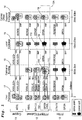
- Fig. 1 illustrates the basic structure of three general, exemplary access network architectures: copper network configurations 11, Fibre-to-the-Building (FTTB)/Fibre-to-the-Cabinet (FTTCab) network configurations 12, and pure fibre network configurations 13, i.e. Fibre-to-the-Home (FTTH).
- FTTB Fibre-to-the-Building
- FTTCab Fibre-to-the-Cabinet
- pure fibre network configurations i.e. Fibre-to-the-Home
- the network configurations 11, 12, 13 commonly originate from regional exchanges 14, also referred to as a central offices (CO), which may provide broadband network access to one or several local exchanges 15.
- the regional exchanges or central offices (CO) 14 are generally located about 20 km to 60 km away from the broadband network user location 17, and the local exchanges 15 about 10 km to 20 km away.
- the local exchanges 15 may in turn be connected to one or several network access nodes (e.g. ONU 110 and IP DSLAM 111) located in, for example, cabinets or buildings 16, etc.
- the cabinets or buildings 16 are usually close to the broadband network user location 17, generally about 500m to 2km away.
- the one or several network access nodes 110, 111 in the cabinets or buildings 16 are arranged to further distribute network access to, for example, individual customers/businesses, etc., located at the broadband network user location 17, also referred to as user premises.
- the copper network configurations 11 normally employ one of the ADSL/ADSL2/ADSL2+ protocols when providing broadband access to end users at the broadband network user location 17.
- the copper network configurations 11 are, however, limited to only provide bandwidths in the low Mbits/s-range due to the restrictions on the physical copper line. For example, noise and bit-loss of the copper line are dependent upon the actual length of the copper line. This also limits the possible range of the copper network configuration 11.
- the pure fibre network configurations (FTTH) 13 may provide noise-free, high capacity access in the Gbits/s-range to users at the broadband network user location 17.
- FTTH pure fibre network configurations
- CO regional exchange/central office
- PON passive optical network
- the FTTB/FTTCab network configurations 12 can be described as a combination of, or bridge between, the copper network configurations 11 and the pure fibre network configurations (FTTH) 13.
- the FTTB/FTTCab network configurations 12 may employ one of the ADSL/ADSL2/ADSL2+/VDSL/VDSL2 protocols when providing broadband access to end users at the broadband network user location 17 over the copper wirings between the broadband network user location 17 and the one or several network access nodes 110, 111 in the cabinets or buildings 16.
- the FTTB/FTTCab network configurations 12 may employ different optical network transmission protocols, such as, for example, for GE/XGE/GPON, etc., when backhauling traffic over the optical network therein between.
- the access network configurations 11, 12, 13 may primarily be used to deliver services to residential and business customers that need high capacity
- the access network configurations 11, 12, 13 may also be used to backhaul mobile traffic from various types of mobile networks, such as, for example, GSM, UMTS, HSPA, LTE, etc.
- the FTTB/FTTCab configurations 12 are probably the most viable and useful solutions today, since copper lines can often be found already deployed close to any antenna or radio base station location. The combination of copper wires and optical fibre solutions may then be used to aggregate and backhaul the mobile traffic.
- the clock synchronisation may be performed based on the physical layer, or on the L2 layer using the protocol IEEE 1588, or on the L3 layer using the Network Timing Protocol, NTP, RFC 1305.
- clocks may be distributed using the physical layer if a synchronous protocol such as, for example, TDM, is used.
- a synchronous protocol such as, for example, TDM
- Accuracy is here dependent on the transmission speed and may yield very high accuracies, that is, in the pico-second range (ps), e.g. about 1-10 ps.
- ps pico-second range
- this may not be accomplished in an Ethernet-based network, since Ethernet-based networks almost always are based on an asynchronous frame transport.
- the recently standardized protocol IEEE 1588 may be used in order to distribute clock synchronisation.
- This protocol may, by using a master/slave principle for small LAN networks comprising several sub-nets, yield accuracies in the low microsecond ( ⁇ s) range, for example, about 1-5 ⁇ s.
- clock synchronisation may be achieved using the Network Timing Protocol NTP (RFC 1305), which is an IP-based protocol for wide area networks (WANs), such as, for example, the Internet, working in a peer ensemble style.
- NTP Network Timing Protocol
- This approach supports accuracies in the few milliseconds range, that is, about 1-10 ms.
- the problem is solved by providing a clocking interconnect between the passive optical network and the copper wire access network, and using the high precision in the synchronisation of the physical layer of the optical transmissions in order to provide an accurate and reliable timing reference for transmissions over the copper wire access network.
- This may then, for example, be used by the applications, services and equipment running on the user side as a more accurate and reliable clock.
- the invention is described in the following in relation to the FTTB/FTTCab access network 12A and 20, as shown in Fig. 1 and 2 , respectively, this should not be considered as limiting the invention.
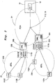
- Fig. 2 shows an FTTB/FTTCab access network 20.
- the FTTB/FTTCab access network 20 may be divided into two main parts, the passive optical network (PON) 21 and the copper wire xDSL access network 22A, 22B.
- PON passive optical network
- the passive optical network 21 may, for example, be a point-to-point Ethernet, a point-to-multipoint Ethernet Passive Optical Network (EPON), a Gigabit-capable Passive Optical Network (GPON), etc. More details about passive optical networks, such as, the passive optical network 21 described herein, may be found in, for example, "Gigabit Small Form Factor Pluggable Module", XFP Revision 4.5, 08/2005; "10 Gbps XFP-E with extended reach 80km with DWDM option", Mitsubishi, 02/2005; G652, "Characteristics of a single-mode optical fiber and cable", ITU-T, 06/2005; G983.1, “Broadband optical access systems based on Passive Optical Networks (PON)", ITU-T, 01/2005; G983.3, "A broadband optical access system with increased service capability by wavelength allocation", ITU-T, 03/2001; G984.1, "Gigabit-capable Passive Optical Networks (GPON): General characteristics
- the copper wire xDSL access network 22A, 22B may, for example, be an ADSL-, ADSL2-, ADSL2plus- or VDSL2-network. More details about copper wire xDSL access networks, such as, the exemplary copper wire xDSL access network 22A, 22B described herein, may be found in, for example, G992.5, "Asymmetric Digital Subscriber Line (ADSL) transceivers - Extended bandwidth ADSL2 (ADSL2+)", ITU-T, 01/2005; and in G993.2, "Very high speed digital subscriber line transceivers 2 (VDSL2)", ITU-T, 03/2006.
- ADSL Asymmetric Digital Subscriber Line
- ADSL2+ Extended bandwidth ADSL2
- VDSL2 Very high speed digital subscriber line transceivers 2
- the regional exchange/central office (CO) 14 may comprise an optical line termination (OLT) 18.
- the optical line termination (OLT) 18 may be arranged to provide a high-capacity optical network access to one or several optical network units 110A, 110B comprised in one or several interconnecting nodes 16A, 16B.
- one or several local exchanges 15, one or several splice points 113, and/or one or several power splits 19 may be provided in between the optical line termination 18 and the one or several optical network units 110A, 110B in the one or several interconnecting nodes 16A, 16B.
- the interconnecting nodes 16A, 16B are often located in buildings or cabinets relatively close to the end user premises 17, hence the use of the name FTTB/FTTCab access network.
- the interconnecting nodes 16A, 16B may further comprise one or several xDSL access devices 111A, 111B.
- the xDSL access device 111A, 111B may, for example, be a IP Digital Subscriber Line Access Multiplexer (DSLAM).
- the xDSL access device 111A, 111B may be arranged to be connected to and to provide network access to one or several user xDSL equipments 112, 112A, 112A', 112B, 112B' over the copper wire xDSL access network 22A, 22B.
- the one or several user xDSL equipments 112, 112A, 112A', 112B, 112B' may also be referred to as customer-premises equipment or customer-provided equipment (CPEs).
- CPEs customer-premises equipment
- the xDSL access device 111A, 111B and the optical network unit 110A, 110B in the interconnecting node 16A, 16B may, for example, be implemented in separate boxes and arranged to connect via an Ethernet-interface, or implemented and arranged to be connected in the same box or on the same printed board assembly.
- a clocking interconnect 23A, 23B is provided between the xDSL access device 111A, 111B and the optical network unit 110A, 110B in the interconnecting node 16A, 16B.
- the clocking interconnect 23A, 23B may be implemented, for example, as an on-board connection via a conductive lane on a printed circuit board assembly. This may be preferable if the xDSL access device 111A, 111B and the ONU unit 110A, 110B are implemented in the same box or on the same printed board assembly in the interconnecting node 16A, 16B.
- the clocking interconnect 23A, 23B may also be implemented, for example, as a separate copper connection or an inband signal via an Ethernet link.
- the xDSL access device 111A, 111B and the ONU unit 110A, 110B are implemented in separate boxes and connects via an Ethernet-interface in the interconnecting node 16A, 16B.
- this allows the ONU unit 110A, 110B in the interconnecting node 16A, 16B to provide it's more reliable and accurate clock signal, obtained through the high precision in the synchronisation of the physical layer of optical transmissions, to the xDSL access device 111A, 111B and the copper wire xDSL access network 22A, 22B.
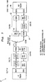
- Fig. 3 shows an illustrative exemplary block diagram describing a PON network 21, an OLT 14 and an ONU 110A, 110B in more detail. It should be noted that most of the units shown in the OLT 14 and the ONU 110A, 110B in Fig. 3 are known, and will therefore not be described in particular detail.
- the Wavelength Division Multiplexing (WDM) receiving unit 41 may receive optical transmissions over the optical fibre distribution network (ODN) located between the OLT 14 and the ONU 110A, 110B.
- the optical transmissions is forwarded to a photo diode 42 which may interpret the optical transmissions into continuous-mode bit-level modulated transmission signals, and output said continuous-mode bit-level modulated transmission signal to a Clock and Data Recovery (CDR) unit 43.
- the CDR unit 43 may be arranged to receive the continuous-mode bit-level modulated transmission signal and output a bit-level clock signal.
- the ONU unit 110, 110A, 110B may be arranged to output this bit-level clock signal, for example, through the clocking interconnect 23A, 23B described above with reference to Fig.
- the ONU interface in the ONU unit 110, 110A, 110B may also enable further attached equipment and systems to be synchronized using the bit-level clock signal obtained by the CDR unit 43.
- the CDR unit 43 may also, for example, output said bit-level clock signal to PON framer circuitry 44 along with recovered data from the continuous-mode bit-level modulated transmission signal.
- the PON framer circuitry 44 in the ONU unit 110, 110A, 110B may further be arranged to obtain a frame-level clock signal from the data received from the CDR unit 43.
- the PON framer circuitry 44 may determine the frame-level clock signal from the downstream framing structure of the physical transport layer of the optical network transmissions. This will be discussed in more detail below with reference to Fig. 4 .
- the PON framer circuitry 44 in the ONU unit 110, 110A, 110B may be arranged to output the frame-level clock signal, for example, through the clocking interconnect 23A, 23B described above with reference to Fig. 2 , and/or through an ONU interface having a signal output arranged to output the obtained frame-level clock signal.
- the ONU interface in the ONU unit 110, 110A, 110B may also enable further attached equipment and systems to be synchronized using the obtained frame-level clock signal.
- the PON framer circuitry 44 may also comprise a SERDES unit arranged to de-serialize input signals and serialize output signals.
- the ONU unit 110, 110A, 110B may be arranged to output either of the bit-level clock signal or the frame-level clock signal through, for example, the clocking interconnect 23A, 23B described above with reference to Fig. 2 , and/or through an ONU interface having a signal output arranged to output the obtained bit-level clock signal or frame-level clock signal.
- the ONU interface in the ONU unit 110, 110A, 110B may then also enable further attached equipment and systems to be synchronized using the obtained bit-level clock signal or frame-level clock signal.
- Fig. 4 illustrates an exemplary frame trail of the GPON Transmission Convergence (GTC) protocol as specified in G984.3, "Gigabit-capable Passive Optical networks (GPON): Transmission convergence layer specifications", ITU-T, 02/2004, and an exemplary lock signal which may be obtained as a frame-level clock signal in an interconnecting node 16A, 16B according to an embodiment of the invention, for example, in the PON framer circuitry 44 in the ONU unit 110, 110A, 110B.
- GTC GPON Transmission Convergence
- GPON Transmission convergence layer specifications
- ITU-T Transmission convergence layer specifications
- lock signal which may be obtained as a frame-level clock signal in an interconnecting node 16A, 16B according to an embodiment of the invention, for example, in the PON framer circuitry 44 in the ONU unit 110, 110A, 110B.
- a common clock may be derived from the optical network transmissions by a PON framer circuitry 44 in any of the ONU units 110, 110A, 110B in the GPON network.
- determine a clock synchronisation in an access network may yield clock accuracies in the low picoseconds range (e.g. 1-10 ps) within a GPON network.
- this clock signal may be used to synchronise any equipment connected to ONU units 110, 110A, 110B in the GPON network, such as, for example, the xDSL access device 111A, 111B in a FTTB/FTTCab scenario.
- all ONU units 110, 110A, 110B may be synchronised to the OLT 18 of the GPON network via the downstream framing structure.
- an upstream burst synchronisation may be derived from this downstream synchronisation. This allows for fully synchronous applications, such as, for example, TDM traffic backhauling and global timing distribution, which may be needed for performing backhauling of mobile network traffic from mobile communications radio base stations (RBSs).
- RBSs radio base stations
- a downstream frame trail for network transmission over the GPON network is illustrated in Fig. 4 .
- This downstream frame trail is described in more detail in the GPON Transmission Convergence (GTC) protocol as specified in G984.3, "Gigabit-capable Passive Optical networks (GPON): Transmission convergence layer specifications", ITU-T, 02/2004.
- the payload in a GTC frame contains a GPON encapsulation Method (GEM) payload, which in turn may comprise Ethernet data traffic.
- GEM GPON encapsulation Method
- Each GTC frame in the exemplary GTC frame trail is commonly prefixed by a Physical Control Block downstream (PCBd) header. The presence of a PCBd header may be used to trigger the lock signal in the PON framer circuitry 44 in the ONU unit 110, 110A, 110B, as can be seen in Fig. 4 .
- PCBd Physical Control Block downstream
- Each GTC frame in the GTC frame trail may be received and decoded by all ONU units 110, 110A, 110B on the GPON network, which is due to the optical tree architecture (as seen in Fig. 2 ).
- the GTC frame duration is given by 125 microseconds ( ⁇ s), which corresponds to a frame rate of 8 kHz. It follows that a frame-level clock derived according to the invention from the PON framer circuitry 44 in the ONU units 110, 110A, 110B, thus may be as accurate as 125 microseconds ( ⁇ s).
- a bit-level clock derived according to the invention from the CDR unit 43 in the ONU units 110, 110A, 110B may, for a 2488.32 Mbit/s downstream data rate wherein the bit duration is about 400 picoseconds (ps), be as accurate as, for example, half a nano-second (ns).
- Fig. 5 shows an exemplary VDSL2 and VTU functional model which may be used in the copper wire xDSL access network 22A, 22B.
- the VDSL2 and VTU functional model is described in more detail in G993.2, "Very high speed digital subscriber line transceivers 2 (VDSL2)", ITU-T, 03/2006, and comprises a Network Timing Reference (NTR) functionality which is arranged to provide an 8 kHz timing marker to be transmitted over the copper wire xDSL access network 22A, 22B in the xDSL Over Head frame.
- the Network Timing Reference (NTR) functionality is also found in, for example, ADSL (ITU-T G.992.1), ADSL2 (ITU-T G.992.3) and ADSL2plus (ITU-T G.992.5).
- the NTR 8 kHz timing marker 54 may be used in order to generate an 8 kHz clock accessible at an NTR output of the xDSL transceiver chip (xTU C) in the user xDSL equipments 112, 112A, 112A', 112B, 112B' or CPEs located at the user premises 17.
- the xTU C may also generate an 8 kHz local timing reference (LTR) by dividing its sampling clock by the appropriate integer.
- LTR local timing reference
- the resulting user premises NTR 8kHz timing marker may then be generated by computing the change in phase offset between the input NTR 8 kHz timing marker 54 received from the xDSL access device 111, 111A, 111B and the LTR.
- the phase offset may be measured as a difference in cycles of the sampling clock.
- phase offset may then be encoded into a single octet and inserted into a returning DSL Over Head frame by the user xDSL equipments 112, 112A, 112A', 112B, 112B' or CPEs at the user premises 17.
- the NTR 8 kHz timing marker 54 of the xDSL access device 111, 111A, 111B may thus, through the clocking interconnect 23A, 23B according to the invention, be synchronised using the bit-level or frame-level clock signal obtained from the optical network transmissions received in the ONU unit 110, 110A, 110B over the PON network 21. This will allows for a highly accurate and reliable clock signal to be used in the xDSL access network 22A, 22B employing traditional copper wiring 53.
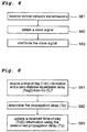
- Fig. 6 shows a flowchart illustrating an exemplary embodiment of the invention.
- an ONU unit 110, 110A, 110B in an interconnecting node 16A, 16B may receive optical network transmissions from an OLT 18 over a PON network 21.
- the ONU unit 110, 110A, 110B may obtain a clock signal from the received optical network transmissions.
- the clock signal may be a frame-level clock signal or a bit-level clock signal, which may be obtained as described in the above mentioned embodiments.
- the ONU unit 110, 110A, 110B may distribute the clock signal to a timing reference input 54 of the at least one xDSL access device 111, 111A, 111B.
- the ONU unit 110, 110A, 110B may distribute the clock signal using the clocking interconnect 23A, 23B as described in the above mentioned embodiments.
- the ONU unit 110, 110A, 110B may also distribute the clock signal to an ONU interface having a signal output, which may be arranged to output said obtained clock signal. This may, for example, be used to synchronize further attached equipment and systems.
- Fig. 7 shows a timing relationship schedule as specified in G984.3, "Gigabit-capable Passive Optical networks (GPON): Transmission convergence layer specifications", ITU-T, 02/2004, between an OLT 18 and an ONU unit 110, 110A, 110B over a PON network 21.
- GPON Gigabit-capable Passive Optical networks
- the zero-distance equalization delay T eqD is composed of two times the propagation delay T p from the OLT 18 to a particular ONU unit 110, 110A, 110B over a PON network 21, the ONU unit response time T res and the assigned equalization delay (EqD).
- the assigned equalization delay EqD may be computed by the OLT 18 during ranging in the PON network 21, and messaged to each ONU unit 110, 110A, 110B in order the achieve an upstream frame alignment at the OLT 18.
- a more accurate and reliable clock may be achieved at the ONU unit 110, 110A, 110B by synchronising the time of the day (ToD) information in the ONU unit 110, 110A, 110B to the global OLT clock.
- the ONU unit 110, 110A, 110B knows the ONU unit response time T res .
- the ONU unit 110, 110A, 110B may upon reception of the following downstream frame, comprising ToD information, update its clock to ToD + T d to get synchronized with the global OLT clock. According to this approach, a clock accuracy of 1 ⁇ s is possible (due to the 1 ⁇ s GPON ranging accuracy requirement).
- Fig. 8 shows a flowchart illustrating an exemplary embodiment of the invention.
- an ONU unit 110, 110A, 110B in an interconnecting node 16A, 16B receives a time-of-day (ToD) information and a zero-distance equalization delay T eqD from the OLT 18 in a downstream frame of an optical network transmission.
- ToD time-of-day
- T eqD zero-distance equalization delay
- the ONU unit 110, 110A, 110B may determine the propagation delay T p .
- the propagation delay T p may be determined according Eq.1 as described above.
- the ONU unit 110, 110A, 110B may update received time-of-day (ToD) information, which may be received from the OLT 18 in another downstream frame of the optical network transmission, using the determined propagation delay (T p ).
- ToD received time-of-day
- time distribution mechanism described above with reference to Figs. 7 and 8 provides an accurate and simple clock synchronisation of the time-of-day (ToD) information in the ONU unit 110, 110A, 110B.
Landscapes
- Engineering & Computer Science (AREA)
- Computer Networks & Wireless Communication (AREA)
- Signal Processing (AREA)
- Small-Scale Networks (AREA)
- Optical Communication System (AREA)
Claims (12)
- Zusammengeschalteter Knoten (16; 16A; 16B) zur Verwendung zum Zusammenschalten eines passiven Glasfasernetzwerks [PON] (21) und eines xDSL-Zugangsnetzwerk (22A; 22B) aus Kupferdraht, wobei der genannte zusammengeschaltete Knoten (16A; 16B)
ein Glasfasernetzwerkgerät [ONU] (110; 110A; 110B), das angeordnet ist, um an einen Glasfaserkabel-Anschluss [OLT] (18) über das PON-Netzwerk (21) angeschlossen zu werden; und wenigstens eine xDSL-Zugangsvorrichtung (111; 111A; 111B) umfasst, die an wenigstens eine benutzerseitige xDSL-Ausrüstung (112; 112A; 112A'; 112B; 112B') über das xDSL-Zugangsnetzwerk (22A; 22B) aus Kupferdraht anschließbar ist,
dadurch gekennzeichnet, dass
der zusammengeschaltete Knoten (16A; 16B) weiterhin umfasst:eine Takterzeugungszusammenschaltung (23A; 23B) zwischen dem ONU-Gerät (110; 110A; 110B) und dem wenigstens einen xDSL-Zugangsgerät (111; 111A; 111B) umfasst, das angeordnet ist, um ein Taktsignal auszugeben, das von den Bit- oder Frameraten von Glasfasernetzwerkübertragungen erhalten wurde, die in dem ONU-Gerät (110; 110A; 110B) über das PON-Netzwerk (21) zu einer Taktreferenzeingabe (54) von dem wenigstens einen xDSL-Zugangsgerät (111; 111A; 111 B) erhalten wird. - Zusammengeschalteter Knoten (16A; 16B) gemäß Anspruch 1, bei dem das genannte ONU-Gerät (110; 110A; 110B) weiterhin ein Uhrzeit- und Datenwiederherstellungs-[CDR]-Gerät (43) umfasst, das angeordnet ist, um das genannte Taktsignal auf einer Bitebene der physischen Transportschicht der Glasfasernetzwerkübertragungen derart zu bestimmen, dass ein Taktsignal auf Bitebene erhalten wird.
- Zusammengeschalteter Knoten (16A; 16B) gemäß Anspruch 1, bei dem das genannte ONU-Gerät (110; 110A; 110B) weiterhin eine PON-Framerschaltung (44) umfasst, die angeordnet ist, um das genannte Taktsignal aus der nachgeschalteten Framing-Struktur der physischen Transportschicht der Glasfasernetzwerkübertragungen derart zu bestimmen, dass ein Frame-Ebenentaktsignal erhalten wird.
- Zusammengeschalteter Knoten (16A; 16B) gemäß Anspruch 1 - 3, bei dem das genannte ONU-Gerät (110; 110A; 110B) eine ONU-Schnittstelle mit einer Signalausgabe umfasst, die angeordnet ist, um das genannte Taktsignal auszugeben und weiterhin angeschlossene Ausrüstungen und Systeme zur Synchronisation unter Verwendung des erhaltenen Taktsignals befähigt.
- Zusammengeschalteter Knoten (16A; 16B) gemäß Anspruch 1 - 4, bei dem die genannte Taktreferenzeingabe der wenigstens einen xDSL-Zugangsvorrichtung (111; 111A; 111 B) die Netzwerk-Zeiterfassungsreferenz-[NTR]-Eingabe (54) auf einem Sender-Empfänger-Chip in einer xDSL-Übertragungseinheitszentrale [xTU-C] in der wenigstens einen xDSL-Zugangsvorrichtung (111; 111A; 111 B) ist.
- Zusammengeschalteter Knoten (16A; 16B) gemäß Anspruch 5, bei dem, wenn die xDSL-Zugangsvorrichtung (111; 111A; 111B) und das ONU-Gerät (110; 110A; 110B) in derselben Box oder auf derselben Leiterplattenstruktur implementiert sind, die genannte Takterzeugungszusammenschaltung (23A; 23B) zwischen dem ONU-Gerät (110; 110A; 110B) und der xDSL-Zugangsvorrichtung (111; 111A; 111 B) ein integrierter Anschluss über eine Leiterbahn auf einer Leiterplattenstruktur ist.
- Zusammengeschalteter Knoten (16A; 16B) gemäß Anspruch 5, bei dem, wenn die xDSL-Zugangsvorrichtung (111; 111A; 111B) und das ONU-Gerät (110; 110A; 110B) in gesonderten Boxen implementiert sind und über eine Ethernet-Schnittstelle angeschlossen sind, die genannte Takterzeugungszusammenschaltung (23A; 23B) zwischen dem ONU-Gerät (110; 110A; 110B) und der xDSL-Zugangsvorrichtung (111; 111A; 111B) entweder ein separater Kupferanschluss oder ein Signal innerhalb eines Bandes über einen Ethernet-Link ist.
- Zusammengeschalteter Knoten (16A; 16B) gemäß Anspruch 1 - 7, bei dem das genannte PON-Netzwerk (21) ein Punkt-zu-Punkt-Ethernet, ein passives Punkt-zu-Multipunkt-Glasfaser-Ethernet-Netzwerk [EPON] oder ein Gigabit-fähiges passives Glasfasernetzwerk [GPON] ist; und das genannte xDSL-Zugangsnetzwerk (22A; 22B) aus Kupferdraht ein ADSL-, ein ADSL2-, ein ADSL2 plus oder ein VDSL2-Netzwerk ist.
- Verfahren zur Verwendung in einem zusammengeschalteten Knoten (16A; 16B), das
ein ONU-Gerät (110; 110A; 110B), das über ein PON-Netzwerk (21) an einen OLT-Anschluss (18) angeschlossen ist und wenigstens eine xDSL-Zugangsvorrichtung (111; 111A; 111B) umfasst, die an wenigstens eine Endbenutzer-xDSL-Ausrüstung (112; 112A; 112A'; 112B; 112B') über ein xDSL-Zugangsnetzwerk (22A; 22B) aus Kupferdraht angeschlossen ist,
dadurch gekennzeichnet, dass
umfassend die Stufen:- des Empfangs von Glasfasernetzwerkübertragungen auf das ONU-Gerät (110; 110A; 110B);- des Erhalts eines Taktsignals aus der Bit- oder Framerate der empfangenen Glasfasernetzwerkübertragungen auf das ONU-Gerät (110; 110A; 110B); und- der Ausgabe des Taktsignals an eine Taktreferenzeingabe (54) der wenigstens einen xDSL-Zugangsvorrichtung (111; 111A; 111 B). - Verfahren gemäß Anspruch 9, bei dem die Stufe des Erhalts des Taktsignals ein moduliertes Bit-Ebenen-Übertragungssignal im kontinuierlichen Modus der physischen Transportschicht der Glasfasernetzwerk-Übertragungen verwendet, um das genannte Taktsignal zu erhalten.
- Verfahren gemäß Anspruch 9, bei dem die Stufe des Erhalts des Taktsignals die nachgelagerte Framing-Struktur der physischen Transportschicht der Glasfasernetzwerkübertragungen verwendet, um das genannte Taktsignal zu erhalten.
- Zugangsnetzwerk (12A; 20) für die Zusammenschaltung eines PON-Netzwerks (21) und eines xDSL-Zugangsnetzwerks (22A; 22B) aus Kupferdraht, bei dem das Zugangsnetzwerk (12A; 20) einen zusammengeschalteten Knoten (16A; 16B) gemäß Anspruch 1 - 8 umfasst.
Applications Claiming Priority (1)
| Application Number | Priority Date | Filing Date | Title |
|---|---|---|---|
| PCT/SE2009/050036 WO2010082879A1 (en) | 2009-01-16 | 2009-01-16 | A method and an interconnecting node for use in an access network |
Publications (2)
| Publication Number | Publication Date |
|---|---|
| EP2380296A1 EP2380296A1 (de) | 2011-10-26 |
| EP2380296B1 true EP2380296B1 (de) | 2016-03-30 |
Family
ID=41130185
Family Applications (1)
| Application Number | Title | Priority Date | Filing Date |
|---|---|---|---|
| EP09788466.2A Active EP2380296B1 (de) | 2009-01-16 | 2009-01-16 | Verfahren und verbindender knoten zur verwendung in einem zugangsnetzwerk |
Country Status (7)
| Country | Link |
|---|---|
| US (1) | US9425983B2 (de) |
| EP (1) | EP2380296B1 (de) |
| CN (1) | CN102282788A (de) |
| AR (1) | AR075141A1 (de) |
| BR (1) | BRPI0923958B1 (de) |
| WO (1) | WO2010082879A1 (de) |
| ZA (1) | ZA201103717B (de) |
Families Citing this family (21)
| Publication number | Priority date | Publication date | Assignee | Title |
|---|---|---|---|---|
| EP2380296B1 (de) * | 2009-01-16 | 2016-03-30 | Telefonaktiebolaget LM Ericsson (publ) | Verfahren und verbindender knoten zur verwendung in einem zugangsnetzwerk |
| DE102011110921A1 (de) | 2011-02-23 | 2012-08-23 | Evonik Goldschmidt Gmbh | Neuartige Polysiloxane mit Betaingruppen, deren Herstellung und Verwendung |
| US8867404B2 (en) * | 2012-02-03 | 2014-10-21 | Futurewei Technologies, Inc. | Node level vectoring synchronization |
| WO2013130647A1 (en) * | 2012-03-02 | 2013-09-06 | Huawei Technologies Co., Ltd. | Passive optical network digital subscriber line convergence architecture |
| GB2510012B (en) | 2012-10-28 | 2015-06-10 | Lantiq Deutschland Gmbh | Method of packet encapsulation for multi-service operation from a distribution point |
| US9473836B2 (en) * | 2014-09-04 | 2016-10-18 | Verizon Patent And Licensing Inc. | Maintaining channel-invariant optical network unit (ONU) equalization delay in a passive optical network |
| US20170302433A1 (en) * | 2015-05-15 | 2017-10-19 | Alcatel-Lucent Usa Inc. | Method And Apparatus For Time Transport In A Communication Network |
| US10341023B2 (en) * | 2016-10-19 | 2019-07-02 | Centurylink Intellectual Property Llc | Terminal enclosure wireless base station |
| US10205552B2 (en) * | 2017-01-20 | 2019-02-12 | Cox Communications, Inc. | Optical communications module link, systems, and methods |
| US11502770B2 (en) | 2017-01-20 | 2022-11-15 | Cox Communications, Inc. | Optical communications module link extender, and related systems and methods |
| US10516922B2 (en) * | 2017-01-20 | 2019-12-24 | Cox Communications, Inc. | Coherent gigabit ethernet and passive optical network coexistence in optical communications module link extender related systems and methods |
| ES2911378T3 (es) * | 2019-01-15 | 2022-05-19 | Deutsche Telekom Ag | Procedimiento para un funcionamiento y arquitectura mejorados y simplificados de un punto de entrega de una oficina central dentro de una red de acceso de banda ancha de una red de telecomunicaciones, para la ejecución mejorada de tareas de conexión a la red, tareas funcionales o de configuración adicionales dentro del punto de entrega de la oficina central, sistema de telecomunicaciones, programa y medio legible por ordenador |
| US10993003B2 (en) | 2019-02-05 | 2021-04-27 | Cox Communications, Inc. | Forty channel optical communications module link extender related systems and methods |
| US10999658B2 (en) | 2019-09-12 | 2021-05-04 | Cox Communications, Inc. | Optical communications module link extender backhaul systems and methods |
| US11317177B2 (en) | 2020-03-10 | 2022-04-26 | Cox Communications, Inc. | Optical communications module link extender, and related systems and methods |
| US11146350B1 (en) | 2020-11-17 | 2021-10-12 | Cox Communications, Inc. | C and L band optical communications module link extender, and related systems and methods |
| US11271670B1 (en) | 2020-11-17 | 2022-03-08 | Cox Communications, Inc. | C and L band optical communications module link extender, and related systems and methods |
| US11323788B1 (en) | 2021-02-12 | 2022-05-03 | Cox Communications, Inc. | Amplification module |
| US12199743B2 (en) | 2021-02-12 | 2025-01-14 | Cox Communications, Inc. | Optical communications module link extender including ethernet and PON amplification |
| US11523193B2 (en) | 2021-02-12 | 2022-12-06 | Cox Communications, Inc. | Optical communications module link extender including ethernet and PON amplification |
| US11689287B2 (en) | 2021-02-12 | 2023-06-27 | Cox Communications, Inc. | Optical communications module link extender including ethernet and PON amplification |
Family Cites Families (41)
| Publication number | Priority date | Publication date | Assignee | Title |
|---|---|---|---|---|
| CN1244751A (zh) | 1998-08-06 | 2000-02-16 | 深圳市华为技术有限公司 | 无源光纤网络系统 |
| JP3444804B2 (ja) * | 1998-11-27 | 2003-09-08 | 沖電気工業株式会社 | 伝送装置 |
| GB2349315B (en) * | 1999-04-16 | 2003-06-04 | Fujitsu Ltd | Delay adjustment unit and method, optical network unit, and communication system |
| GB2359960B (en) * | 2000-03-03 | 2004-06-16 | Mitel Corp | Embedded loop delay compensation circuit for multi-channel transceiver |
| DE60031841T2 (de) * | 2000-06-16 | 2007-09-13 | Alcatel Lucent | Verfahren zur Übertragung eines Referenztaktsignals |
| KR100387251B1 (ko) * | 2000-08-10 | 2003-06-12 | 주식회사 경동보일러 | 보일러의 난방제어장치 및 그 방법 |
| US6470032B2 (en) | 2001-03-20 | 2002-10-22 | Alloptic, Inc. | System and method for synchronizing telecom-related clocks in ethernet-based passive optical access network |
| US20020171895A1 (en) * | 2001-04-25 | 2002-11-21 | Glory Telecommunications Co., Ltd. | Automatic ranging in a passive optical network |
| KR100438824B1 (ko) * | 2001-08-23 | 2004-07-05 | 삼성전자주식회사 | 일대다 데이타 통신망의 전파 지연 보상 방법들 |
| KR100454958B1 (ko) * | 2002-04-18 | 2004-11-06 | 삼성전자주식회사 | 디지털 방송 서비스에서의 채널 변경 방법 |
| US7118281B2 (en) * | 2002-08-09 | 2006-10-10 | Jds Uniphase Corporation | Retention and release mechanisms for fiber optic modules |
| US7239670B2 (en) * | 2002-12-11 | 2007-07-03 | Broadcom Corporation | Pre-emphasis of TMDS signalling in video applications |
| EP1432160B1 (de) * | 2002-12-18 | 2006-06-21 | Alcatel | Verfahren und System zum Bearbeiten von Daten zwischen einer Schaltungsanordnung zur Rückgewinnung einesTaktsignals und eins Datensignals und einer Datenverarbeitungseinheit in asynchronen Netzwerken |
| US8027473B2 (en) * | 2003-01-13 | 2011-09-27 | Conexant Systems, Inc. | System and method for improved data protection in PONs |
| US7450520B2 (en) * | 2003-02-14 | 2008-11-11 | Nortel Networks Limited | Remote interface for a network device in the physical plant |
| DE602005026482D1 (de) * | 2004-06-14 | 2011-04-07 | Broadcom Corp | Kompensation und Messung der Differentiellen Verzögerung in gebundenen Systemen |
| JP5146681B2 (ja) * | 2006-03-16 | 2013-02-20 | 日本電気株式会社 | 量子暗号伝送システムおよび光回路 |
| JP2007295151A (ja) * | 2006-04-24 | 2007-11-08 | Sumitomo Electric Ind Ltd | Ponシステムとこれに使用する局側装置及び端末装置 |
| JP4882614B2 (ja) * | 2006-09-01 | 2012-02-22 | 富士通株式会社 | ビットレート混在光通信方法並びに光加入者装置及び光局側装置 |
| JP4096017B2 (ja) * | 2006-10-13 | 2008-06-04 | 株式会社日立コミュニケーションテクノロジー | 光信号送信タイミング調整方法 |
| CN101001121A (zh) | 2007-01-09 | 2007-07-18 | 湖南大学 | 一种结构简单的光纤无线通信毫米波解调方法和系统 |
| US20090180783A1 (en) * | 2008-01-11 | 2009-07-16 | Tellabs Petaluma, Inc. | Method, network, apparatus and computer program for using leaky counters in clock and data recovery circuits |
| US8483561B2 (en) * | 2008-02-11 | 2013-07-09 | Telefonaktiebolaget Lm Ericsson (Publ) | Remote powering for FTTX via existing wire |
| US8139605B2 (en) * | 2008-05-05 | 2012-03-20 | Calix, Inc. | Upgrade resilient multi-transport optical network terminal |
| US7773606B2 (en) * | 2008-09-22 | 2010-08-10 | Telefonaktiebolaget L M Ericsson (Publ) | Timing distribution within a network element while supporting multiple timing domains |
| US8274998B2 (en) * | 2008-10-02 | 2012-09-25 | Cortina Systems, Inc. | Systems and methods for packet based timing offset determination using timing adjustment information |
| US8902932B2 (en) * | 2008-10-02 | 2014-12-02 | Cortina Systems, Inc. | Systems and methods for a network device to update timing packets to reflect delay |
| US8942561B2 (en) * | 2008-10-21 | 2015-01-27 | Broadcom Corporation | Synchronization transport over passive optical networks |
| US8855491B2 (en) * | 2008-12-30 | 2014-10-07 | Broadcom Corporation | Techniques for protecting passive optical networks |
| EP2380296B1 (de) * | 2009-01-16 | 2016-03-30 | Telefonaktiebolaget LM Ericsson (publ) | Verfahren und verbindender knoten zur verwendung in einem zugangsnetzwerk |
| US20100183316A1 (en) * | 2009-01-20 | 2010-07-22 | Telefonaktiebolaget L M Ericsson (Publ) | Methods and Systems for Dynamic Equalization Delay Passive Optical Networks |
| WO2010098701A1 (en) * | 2009-02-24 | 2010-09-02 | Telefonaktiebolaget Lm Ericsson (Publ) | Dynamic scheduling using pon bandwidth allocation on lower aggregation levels |
| WO2011022883A1 (zh) * | 2009-08-26 | 2011-03-03 | 华为技术有限公司 | 光网络倒换保护方法、装置及系统 |
| US8718482B1 (en) * | 2009-11-10 | 2014-05-06 | Calix, Inc. | Transparent clock for precision timing distribution |
| CN102075240B (zh) * | 2009-11-24 | 2015-06-03 | 中兴通讯股份有限公司 | 一种无源光网络中光网络单元的测距方法及系统 |
| CN102136900B (zh) * | 2010-01-22 | 2014-11-05 | 华为技术有限公司 | 无源光网络的时间同步方法、装置及系统 |
| US8582606B2 (en) * | 2010-05-24 | 2013-11-12 | Cortina Systems, Inc. | Network system with synchronization and method of operation thereof |
| WO2012003481A1 (en) * | 2010-07-02 | 2012-01-05 | Huawei Technologies Co., Ltd. | Method for accurate distribution of time to a receiver node in an access network |
| JP5576747B2 (ja) * | 2010-09-06 | 2014-08-20 | 株式会社日立製作所 | 通信システム及び時刻同期方法 |
| US9264213B2 (en) * | 2011-02-08 | 2016-02-16 | Mitsubishi Electric Corporation | Time synchronization method for communication system, slave station apparatus, master station apparatus, control device, and program |
| EP2845325B1 (de) * | 2012-05-02 | 2017-08-16 | Huawei Technologies Co., Ltd. | Ausrichtung der uplink-dmt-symbole für mehrere leitungen in einem tdd-dsl-system |
-
2009
- 2009-01-16 EP EP09788466.2A patent/EP2380296B1/de active Active
- 2009-01-16 US US13/143,513 patent/US9425983B2/en active Active
- 2009-01-16 WO PCT/SE2009/050036 patent/WO2010082879A1/en not_active Ceased
- 2009-01-16 BR BRPI0923958-8A patent/BRPI0923958B1/pt active IP Right Grant
- 2009-01-16 CN CN2009801549583A patent/CN102282788A/zh active Pending
-
2010
- 2010-01-15 AR ARP100100101A patent/AR075141A1/es not_active Application Discontinuation
-
2011
- 2011-05-20 ZA ZA2011/03717A patent/ZA201103717B/en unknown
Also Published As
| Publication number | Publication date |
|---|---|
| US20120020668A1 (en) | 2012-01-26 |
| EP2380296A1 (de) | 2011-10-26 |
| BRPI0923958B1 (pt) | 2020-10-06 |
| ZA201103717B (en) | 2012-12-27 |
| WO2010082879A1 (en) | 2010-07-22 |
| AR075141A1 (es) | 2011-03-09 |
| US9425983B2 (en) | 2016-08-23 |
| CN102282788A (zh) | 2011-12-14 |
| BRPI0923958A2 (pt) | 2016-04-26 |
Similar Documents
| Publication | Publication Date | Title |
|---|---|---|
| EP2380296B1 (de) | Verfahren und verbindender knoten zur verwendung in einem zugangsnetzwerk | |
| US8625640B2 (en) | Transparent clocks in access networks | |
| EP2772066B1 (de) | Schnittstelle und verfahren zur verbindung einer host-vorrichtung und eines steckmoduls mit kleinem formfaktor | |
| US7864747B2 (en) | System and method for communicating timing to a remote node | |
| US7555015B2 (en) | System and method for synchronizing telecom-related clocks across an unsynchronized point-to-point network connection | |
| US8565605B2 (en) | Burst mode to continuous mode converter | |
| EP2862299B1 (de) | Zeitdomänen in einem pon | |
| US20100183316A1 (en) | Methods and Systems for Dynamic Equalization Delay Passive Optical Networks | |
| US20100189440A1 (en) | Methods and Systems for Transmitting Data in Scalable Passive Optical Networks | |
| KR100606027B1 (ko) | 수동형 광 가입자망을 통한 이더넷 프레임 전송시 왕복시간지연을 보상하는 방법 및 그 수동형 광 가입자망 시스템 | |
| Abdellaoui et al. | Giga Passive Optical Network GPON Based upon Fiber to the Home FTTH: Design, Implementation and Evaluation | |
| Horiuchi | Optical transport technologies in mobile broadband radio systems | |
| Neri et al. | Passive Optical Networks | |
| Shea et al. | PONdering the Access Network | |
| Aweya | Backhaul over Gigabit Passive Optical Networks (GPONs)–Network Architectures and Synchronization Issues | |
| Skaljo et al. | Clock recovery where GPON is used as a Mobile back-haul |
Legal Events
| Date | Code | Title | Description |
|---|---|---|---|
| PUAI | Public reference made under article 153(3) epc to a published international application that has entered the european phase |
Free format text: ORIGINAL CODE: 0009012 |
|
| 17P | Request for examination filed |
Effective date: 20110712 |
|
| AK | Designated contracting states |
Kind code of ref document: A1 Designated state(s): AT BE BG CH CY CZ DE DK EE ES FI FR GB GR HR HU IE IS IT LI LT LU LV MC MK MT NL NO PL PT RO SE SI SK TR |
|
| DAX | Request for extension of the european patent (deleted) | ||
| 17Q | First examination report despatched |
Effective date: 20120806 |
|
| GRAP | Despatch of communication of intention to grant a patent |
Free format text: ORIGINAL CODE: EPIDOSNIGR1 |
|
| INTG | Intention to grant announced |
Effective date: 20150918 |
|
| GRAS | Grant fee paid |
Free format text: ORIGINAL CODE: EPIDOSNIGR3 |
|
| RIN1 | Information on inventor provided before grant (corrected) |
Inventor name: ERIKSSON, PER-ERIK Inventor name: TROJER, ELMAR |
|
| GRAA | (expected) grant |
Free format text: ORIGINAL CODE: 0009210 |
|
| AK | Designated contracting states |
Kind code of ref document: B1 Designated state(s): AT BE BG CH CY CZ DE DK EE ES FI FR GB GR HR HU IE IS IT LI LT LU LV MC MK MT NL NO PL PT RO SE SI SK TR |
|
| REG | Reference to a national code |
Ref country code: GB Ref legal event code: FG4D |
|
| REG | Reference to a national code |
Ref country code: CH Ref legal event code: EP |
|
| REG | Reference to a national code |
Ref country code: AT Ref legal event code: REF Ref document number: 786401 Country of ref document: AT Kind code of ref document: T Effective date: 20160415 |
|
| REG | Reference to a national code |
Ref country code: IE Ref legal event code: FG4D |
|
| REG | Reference to a national code |
Ref country code: DE Ref legal event code: R096 Ref document number: 602009037336 Country of ref document: DE |
|
| REG | Reference to a national code |
Ref country code: LT Ref legal event code: MG4D |
|
| PG25 | Lapsed in a contracting state [announced via postgrant information from national office to epo] |
Ref country code: NO Free format text: LAPSE BECAUSE OF FAILURE TO SUBMIT A TRANSLATION OF THE DESCRIPTION OR TO PAY THE FEE WITHIN THE PRESCRIBED TIME-LIMIT Effective date: 20160630 Ref country code: FI Free format text: LAPSE BECAUSE OF FAILURE TO SUBMIT A TRANSLATION OF THE DESCRIPTION OR TO PAY THE FEE WITHIN THE PRESCRIBED TIME-LIMIT Effective date: 20160330 Ref country code: GR Free format text: LAPSE BECAUSE OF FAILURE TO SUBMIT A TRANSLATION OF THE DESCRIPTION OR TO PAY THE FEE WITHIN THE PRESCRIBED TIME-LIMIT Effective date: 20160701 Ref country code: HR Free format text: LAPSE BECAUSE OF FAILURE TO SUBMIT A TRANSLATION OF THE DESCRIPTION OR TO PAY THE FEE WITHIN THE PRESCRIBED TIME-LIMIT Effective date: 20160330 |
|
| REG | Reference to a national code |
Ref country code: NL Ref legal event code: MP Effective date: 20160330 |
|
| REG | Reference to a national code |
Ref country code: AT Ref legal event code: MK05 Ref document number: 786401 Country of ref document: AT Kind code of ref document: T Effective date: 20160330 |
|
| PG25 | Lapsed in a contracting state [announced via postgrant information from national office to epo] |
Ref country code: LV Free format text: LAPSE BECAUSE OF FAILURE TO SUBMIT A TRANSLATION OF THE DESCRIPTION OR TO PAY THE FEE WITHIN THE PRESCRIBED TIME-LIMIT Effective date: 20160330 Ref country code: SE Free format text: LAPSE BECAUSE OF FAILURE TO SUBMIT A TRANSLATION OF THE DESCRIPTION OR TO PAY THE FEE WITHIN THE PRESCRIBED TIME-LIMIT Effective date: 20160330 Ref country code: LT Free format text: LAPSE BECAUSE OF FAILURE TO SUBMIT A TRANSLATION OF THE DESCRIPTION OR TO PAY THE FEE WITHIN THE PRESCRIBED TIME-LIMIT Effective date: 20160330 |
|
| PG25 | Lapsed in a contracting state [announced via postgrant information from national office to epo] |
Ref country code: NL Free format text: LAPSE BECAUSE OF FAILURE TO SUBMIT A TRANSLATION OF THE DESCRIPTION OR TO PAY THE FEE WITHIN THE PRESCRIBED TIME-LIMIT Effective date: 20160330 |
|
| PG25 | Lapsed in a contracting state [announced via postgrant information from national office to epo] |
Ref country code: EE Free format text: LAPSE BECAUSE OF FAILURE TO SUBMIT A TRANSLATION OF THE DESCRIPTION OR TO PAY THE FEE WITHIN THE PRESCRIBED TIME-LIMIT Effective date: 20160330 Ref country code: IS Free format text: LAPSE BECAUSE OF FAILURE TO SUBMIT A TRANSLATION OF THE DESCRIPTION OR TO PAY THE FEE WITHIN THE PRESCRIBED TIME-LIMIT Effective date: 20160730 Ref country code: PL Free format text: LAPSE BECAUSE OF FAILURE TO SUBMIT A TRANSLATION OF THE DESCRIPTION OR TO PAY THE FEE WITHIN THE PRESCRIBED TIME-LIMIT Effective date: 20160330 |
|
| PG25 | Lapsed in a contracting state [announced via postgrant information from national office to epo] |
Ref country code: SK Free format text: LAPSE BECAUSE OF FAILURE TO SUBMIT A TRANSLATION OF THE DESCRIPTION OR TO PAY THE FEE WITHIN THE PRESCRIBED TIME-LIMIT Effective date: 20160330 Ref country code: CZ Free format text: LAPSE BECAUSE OF FAILURE TO SUBMIT A TRANSLATION OF THE DESCRIPTION OR TO PAY THE FEE WITHIN THE PRESCRIBED TIME-LIMIT Effective date: 20160330 Ref country code: PT Free format text: LAPSE BECAUSE OF FAILURE TO SUBMIT A TRANSLATION OF THE DESCRIPTION OR TO PAY THE FEE WITHIN THE PRESCRIBED TIME-LIMIT Effective date: 20160801 Ref country code: AT Free format text: LAPSE BECAUSE OF FAILURE TO SUBMIT A TRANSLATION OF THE DESCRIPTION OR TO PAY THE FEE WITHIN THE PRESCRIBED TIME-LIMIT Effective date: 20160330 Ref country code: RO Free format text: LAPSE BECAUSE OF FAILURE TO SUBMIT A TRANSLATION OF THE DESCRIPTION OR TO PAY THE FEE WITHIN THE PRESCRIBED TIME-LIMIT Effective date: 20160330 Ref country code: ES Free format text: LAPSE BECAUSE OF FAILURE TO SUBMIT A TRANSLATION OF THE DESCRIPTION OR TO PAY THE FEE WITHIN THE PRESCRIBED TIME-LIMIT Effective date: 20160330 |
|
| PG25 | Lapsed in a contracting state [announced via postgrant information from national office to epo] |
Ref country code: IT Free format text: LAPSE BECAUSE OF FAILURE TO SUBMIT A TRANSLATION OF THE DESCRIPTION OR TO PAY THE FEE WITHIN THE PRESCRIBED TIME-LIMIT Effective date: 20160330 Ref country code: BE Free format text: LAPSE BECAUSE OF FAILURE TO SUBMIT A TRANSLATION OF THE DESCRIPTION OR TO PAY THE FEE WITHIN THE PRESCRIBED TIME-LIMIT Effective date: 20160330 |
|
| REG | Reference to a national code |
Ref country code: DE Ref legal event code: R097 Ref document number: 602009037336 Country of ref document: DE |
|
| PG25 | Lapsed in a contracting state [announced via postgrant information from national office to epo] |
Ref country code: DK Free format text: LAPSE BECAUSE OF FAILURE TO SUBMIT A TRANSLATION OF THE DESCRIPTION OR TO PAY THE FEE WITHIN THE PRESCRIBED TIME-LIMIT Effective date: 20160330 |
|
| PLBE | No opposition filed within time limit |
Free format text: ORIGINAL CODE: 0009261 |
|
| STAA | Information on the status of an ep patent application or granted ep patent |
Free format text: STATUS: NO OPPOSITION FILED WITHIN TIME LIMIT |
|
| 26N | No opposition filed |
Effective date: 20170103 |
|
| PG25 | Lapsed in a contracting state [announced via postgrant information from national office to epo] |
Ref country code: SI Free format text: LAPSE BECAUSE OF FAILURE TO SUBMIT A TRANSLATION OF THE DESCRIPTION OR TO PAY THE FEE WITHIN THE PRESCRIBED TIME-LIMIT Effective date: 20160330 |
|
| PGFP | Annual fee paid to national office [announced via postgrant information from national office to epo] |
Ref country code: GB Payment date: 20170127 Year of fee payment: 9 |
|
| REG | Reference to a national code |
Ref country code: CH Ref legal event code: PL |
|
| PG25 | Lapsed in a contracting state [announced via postgrant information from national office to epo] |
Ref country code: MC Free format text: LAPSE BECAUSE OF FAILURE TO SUBMIT A TRANSLATION OF THE DESCRIPTION OR TO PAY THE FEE WITHIN THE PRESCRIBED TIME-LIMIT Effective date: 20160330 |
|
| REG | Reference to a national code |
Ref country code: FR Ref legal event code: ST Effective date: 20170929 |
|
| PG25 | Lapsed in a contracting state [announced via postgrant information from national office to epo] |
Ref country code: CH Free format text: LAPSE BECAUSE OF NON-PAYMENT OF DUE FEES Effective date: 20170131 Ref country code: LI Free format text: LAPSE BECAUSE OF NON-PAYMENT OF DUE FEES Effective date: 20170131 Ref country code: FR Free format text: LAPSE BECAUSE OF NON-PAYMENT OF DUE FEES Effective date: 20170131 |
|
| REG | Reference to a national code |
Ref country code: IE Ref legal event code: MM4A |
|
| PG25 | Lapsed in a contracting state [announced via postgrant information from national office to epo] |
Ref country code: LU Free format text: LAPSE BECAUSE OF NON-PAYMENT OF DUE FEES Effective date: 20170116 |
|
| PG25 | Lapsed in a contracting state [announced via postgrant information from national office to epo] |
Ref country code: IE Free format text: LAPSE BECAUSE OF NON-PAYMENT OF DUE FEES Effective date: 20170116 |
|
| GBPC | Gb: european patent ceased through non-payment of renewal fee |
Effective date: 20180116 |
|
| PG25 | Lapsed in a contracting state [announced via postgrant information from national office to epo] |
Ref country code: MT Free format text: LAPSE BECAUSE OF NON-PAYMENT OF DUE FEES Effective date: 20170116 |
|
| PG25 | Lapsed in a contracting state [announced via postgrant information from national office to epo] |
Ref country code: GB Free format text: LAPSE BECAUSE OF NON-PAYMENT OF DUE FEES Effective date: 20180116 |
|
| PG25 | Lapsed in a contracting state [announced via postgrant information from national office to epo] |
Ref country code: HU Free format text: LAPSE BECAUSE OF FAILURE TO SUBMIT A TRANSLATION OF THE DESCRIPTION OR TO PAY THE FEE WITHIN THE PRESCRIBED TIME-LIMIT; INVALID AB INITIO Effective date: 20090116 |
|
| PG25 | Lapsed in a contracting state [announced via postgrant information from national office to epo] |
Ref country code: BG Free format text: LAPSE BECAUSE OF FAILURE TO SUBMIT A TRANSLATION OF THE DESCRIPTION OR TO PAY THE FEE WITHIN THE PRESCRIBED TIME-LIMIT Effective date: 20160330 |
|
| PG25 | Lapsed in a contracting state [announced via postgrant information from national office to epo] |
Ref country code: CY Free format text: LAPSE BECAUSE OF NON-PAYMENT OF DUE FEES Effective date: 20160330 |
|
| PG25 | Lapsed in a contracting state [announced via postgrant information from national office to epo] |
Ref country code: MK Free format text: LAPSE BECAUSE OF FAILURE TO SUBMIT A TRANSLATION OF THE DESCRIPTION OR TO PAY THE FEE WITHIN THE PRESCRIBED TIME-LIMIT Effective date: 20160330 |
|
| PG25 | Lapsed in a contracting state [announced via postgrant information from national office to epo] |
Ref country code: TR Free format text: LAPSE BECAUSE OF FAILURE TO SUBMIT A TRANSLATION OF THE DESCRIPTION OR TO PAY THE FEE WITHIN THE PRESCRIBED TIME-LIMIT Effective date: 20160330 |
|
| PGFP | Annual fee paid to national office [announced via postgrant information from national office to epo] |
Ref country code: DE Payment date: 20250129 Year of fee payment: 17 |