EP2379945B1 - Chambre annulaire de combustion de turbomachine à une seule rangée annulaire d'orifices d'entrée d'air primaire et de dilution - Google Patents
Chambre annulaire de combustion de turbomachine à une seule rangée annulaire d'orifices d'entrée d'air primaire et de dilution Download PDFInfo
- Publication number
- EP2379945B1 EP2379945B1 EP09752198.3A EP09752198A EP2379945B1 EP 2379945 B1 EP2379945 B1 EP 2379945B1 EP 09752198 A EP09752198 A EP 09752198A EP 2379945 B1 EP2379945 B1 EP 2379945B1
- Authority
- EP
- European Patent Office
- Prior art keywords
- chamber
- orifices
- wall
- air
- revolution
- Prior art date
- Legal status (The legal status is an assumption and is not a legal conclusion. Google has not performed a legal analysis and makes no representation as to the accuracy of the status listed.)
- Not-in-force
Links
- 238000002485 combustion reaction Methods 0.000 title claims description 35
- 238000010790 dilution Methods 0.000 title claims description 30
- 239000012895 dilution Substances 0.000 title claims description 30
- 238000002347 injection Methods 0.000 claims description 19
- 239000007924 injection Substances 0.000 claims description 19
- 238000011144 upstream manufacturing Methods 0.000 claims description 14
- 239000000446 fuel Substances 0.000 claims description 12
- 238000001816 cooling Methods 0.000 claims description 7
- MWUXSHHQAYIFBG-UHFFFAOYSA-N nitrogen oxide Inorganic materials O=[N] MWUXSHHQAYIFBG-UHFFFAOYSA-N 0.000 description 24
- 210000003462 vein Anatomy 0.000 description 5
- 239000000243 solution Substances 0.000 description 4
- 238000000034 method Methods 0.000 description 3
- 239000000567 combustion gas Substances 0.000 description 2
- 238000004519 manufacturing process Methods 0.000 description 2
- 239000000203 mixture Substances 0.000 description 2
- 230000015572 biosynthetic process Effects 0.000 description 1
- 150000001875 compounds Chemical class 0.000 description 1
- 230000003247 decreasing effect Effects 0.000 description 1
- 230000009977 dual effect Effects 0.000 description 1
- 230000002349 favourable effect Effects 0.000 description 1
- 239000003517 fume Substances 0.000 description 1
- 238000003754 machining Methods 0.000 description 1
- 238000010791 quenching Methods 0.000 description 1
Images


Classifications
-
- F—MECHANICAL ENGINEERING; LIGHTING; HEATING; WEAPONS; BLASTING
- F23—COMBUSTION APPARATUS; COMBUSTION PROCESSES
- F23R—GENERATING COMBUSTION PRODUCTS OF HIGH PRESSURE OR HIGH VELOCITY, e.g. GAS-TURBINE COMBUSTION CHAMBERS
- F23R3/00—Continuous combustion chambers using liquid or gaseous fuel
- F23R3/02—Continuous combustion chambers using liquid or gaseous fuel characterised by the air-flow or gas-flow configuration
- F23R3/04—Air inlet arrangements
- F23R3/06—Arrangement of apertures along the flame tube
-
- F—MECHANICAL ENGINEERING; LIGHTING; HEATING; WEAPONS; BLASTING
- F23—COMBUSTION APPARATUS; COMBUSTION PROCESSES
- F23R—GENERATING COMBUSTION PRODUCTS OF HIGH PRESSURE OR HIGH VELOCITY, e.g. GAS-TURBINE COMBUSTION CHAMBERS
- F23R3/00—Continuous combustion chambers using liquid or gaseous fuel
- F23R3/02—Continuous combustion chambers using liquid or gaseous fuel characterised by the air-flow or gas-flow configuration
- F23R3/04—Air inlet arrangements
- F23R3/10—Air inlet arrangements for primary air
-
- F—MECHANICAL ENGINEERING; LIGHTING; HEATING; WEAPONS; BLASTING
- F23—COMBUSTION APPARATUS; COMBUSTION PROCESSES
- F23R—GENERATING COMBUSTION PRODUCTS OF HIGH PRESSURE OR HIGH VELOCITY, e.g. GAS-TURBINE COMBUSTION CHAMBERS
- F23R3/00—Continuous combustion chambers using liquid or gaseous fuel
- F23R3/42—Continuous combustion chambers using liquid or gaseous fuel characterised by the arrangement or form of the flame tubes or combustion chambers
- F23R3/50—Combustion chambers comprising an annular flame tube within an annular casing
-
- Y—GENERAL TAGGING OF NEW TECHNOLOGICAL DEVELOPMENTS; GENERAL TAGGING OF CROSS-SECTIONAL TECHNOLOGIES SPANNING OVER SEVERAL SECTIONS OF THE IPC; TECHNICAL SUBJECTS COVERED BY FORMER USPC CROSS-REFERENCE ART COLLECTIONS [XRACs] AND DIGESTS
- Y02—TECHNOLOGIES OR APPLICATIONS FOR MITIGATION OR ADAPTATION AGAINST CLIMATE CHANGE
- Y02T—CLIMATE CHANGE MITIGATION TECHNOLOGIES RELATED TO TRANSPORTATION
- Y02T50/00—Aeronautics or air transport
- Y02T50/60—Efficient propulsion technologies, e.g. for aircraft
Definitions
- the present invention relates to an annular combustion chamber of a turbomachine, such as an airplane turbojet or turboprop.
- Such a combustion chamber comprises two coaxial walls of revolution which extend one inside the other and which are connected at their upstream ends by an annular wall of the chamber bottom having openings in which are mounted fuel injection systems.
- the inner and outer walls of the chamber have primary air inlet ports and dilution air inlet ports.
- each wall of the chamber has an annular row of primary air inlet ports and an annular row of dilution air inlet ports, the inlet port array of primary air being located upstream of the row of dilution air inlets.
- the air supplied through the primary air inlet ports is intended to prevent recirculation zones in the chamber and to supply air to the chamber to ensure stoichiometric fuel combustion, and air that passes through the dilution air inlet orifices of the chamber makes it possible to control the temperature profile in the chamber by reducing the temperature of the combustion gases to a temperature acceptable by the turbomachine turbine, mounted downstream of the chamber .
- Nitrogen oxides are produced in the stoichiometric combustion zone and the adjacent zones, where the richness of the air-fuel mixture is between 0.7 and 1.3, and are discharged into the atmosphere. It is essentially in the intermediate volume of the chamber located between the row of primary air inlet ports and the row of dilution air inlet ports that the nitrogen oxides are produced.
- Another known solution is to achieve a staged combustion in a double head chamber comprising two sets of injection systems and two combustion zones optimized for low speeds and for high speeds, respectively.
- the disadvantages of this solution are its greater mass, its cost and the complexity of controlling the chamber.
- Another technique is to use a multipoint chamber in which all the primary air is introduced through the bottom of the chamber through the injection system to create a lean mixture at high speeds and locally rich areas at idle (see for example the document US 2004-025508 the applicant and the document EP 1 235 032 ). This technique reduces the formation of nitrogen oxides but remains complex and expensive.
- the invention particularly aims to reduce the emissions of nitrogen oxides in a turbomachine combustion chamber, in a simple, efficient and economical way.
- annular combustion chamber of a turbomachine such as a turbojet or an airplane turboprop, comprising coaxial revolution walls extending one inside the other and having primary air inlet ports and dilution air inlet ports in the chamber, the primary air inlet and the dilution air inlet ports of each wall being aligned with each other and form a single annular row of orifices.
- the combustion chamber comprises a chamber bottom wall connecting the upstream ends of its walls of revolution and having openings in which are mounted fuel injection systems and baffles.
- the distance between the annular row of orifices of each wall and this deflector, measured along the axis of the corresponding opening, is advantageously substantially equal to half the height of the primary zone of combustion in the chamber, for ensure that a primary air flow rate and dilution air flow enters the chamber through the above-mentioned openings.
- Each wall of the combustion chamber according to the invention therefore comprises a single row of primary air inlet and dilution air ports, against two in the prior art.
- the invention thus makes it possible to eliminate (and not to reduce, as was the case in the prior art) the intermediate volume of the chamber, and thus to significantly reduce the nitrogen oxide emissions of the chamber. . It also makes it possible to reduce the cost of manufacturing the walls of the chamber by eliminating the machining of an annular row of orifices.
- the orifices in each wall of the chamber serve both the primary air inlet and the dilution air in the chamber. Only part of the primary air flow passing through the primary air inlet ports in the prior art is intended to pass through the primary air and dilution air ports of the chamber. The other part of the primary air flow is intended to supply the fuel injection systems mounted on the bottom wall of the chamber of the combustion chamber.
- the portion of the primary air flow passing through the orifices according to the invention serves only to prevent the recirculation zones in the chamber and represents about 25% of the total primary air flow rate.
- the portion of the primary air passing through the chamber injection systems provides the air supply to the chamber and represents about 75% of the total primary air flow.
- the invention thus makes it possible to dissociate the two aforementioned functions that were provided in the prior art by the only primary air inlet orifices of the chamber.
- the orifices of each wall of the chamber are located on a curve centered on the longitudinal axis of the chamber.
- the line on which the orifices are located is substantially circular.
- the orifices are then located in a transverse plane, this plane may be perpendicular to the axis of the chamber.
- each wall of the chamber may be located on a line formed by circular arcs or corrugations.
- the walls of the chamber may further include multiperforations for the passage of cooling air.
- the primary air inlet and dilution air ports of each wall are preferably regularly distributed around the longitudinal axis of the chamber.
- the shape and / or the dimensions of the orifices of each wall may be substantially identical or different, in particular depending on the position of the orifices relative to the fuel injection systems mounted upstream of the chamber.
- the number of primary air and dilution air ports of each wall of the chamber is equal to k times the number of these injection systems, k being equal to 2, 3 or 4.
- the primary air and dilution air orifices preferentially have a diameter of between 5 and 20 mm, and preferably between 10 and 15 mm.
- the aforementioned injection systems may comprise air supply means for the chamber with a portion of the primary air flow intended to enter the chamber, the other part of the primary air flow being intended to pass through. the orifices of each wall of the chamber, as described above.
- the invention also relates to a turbomachine, such as an airplane turbojet or turboprop, characterized in that it comprises a combustion chamber as described above.
- FIG. 1 represents an annular combustion chamber 10 of a turbomachine which is arranged at the outlet of a diffuser 12, itself located at the outlet of a compressor, not shown, and which comprises walls of internal revolution 14 and external 16 connected upstream by an annular wall 18 of the chamber bottom.
- the walls 14, 16 of the chamber are attached downstream by annular flanges internal 20 and outer 22 respectively on an inner frustoconical web 24 of the diffuser, and on one end of an outer casing 26 of the chamber, the upstream end of this housing 26 being connected to an outer frustoconical web 28 of the diffuser.
- the wall 18 of the chamber bottom has openings 30 ( Figures 1 and 2 ) through which air from the diffuser 12 and the fuel fed by the injectors 32 fixed to the outer casing 26 and regularly distributed over a circumference about the longitudinal axis 34 of the chamber.
- Each injector 32 comprises a fuel injection head 36 mounted in an opening 30 of the annular wall 18 and aligned with the axis 38 of this opening 30.
- the internal vein 44 is formed between the internal web 24 of the diffuser 12 and the inner wall 14 of the chamber, and the air passing through this vein is divided into a flow 50 which enters the chamber 10 by two rows of orifices. 52, 54 of the inner wall 14 and a flow 57 which passes through holes 58 of the inner flange 20 of the chamber to go cool components, not shown, located downstream of this chamber.
- the outer vein 46 is formed between the outer casing 26 and the outer wall 16 of the chamber, and the air passing through this vein is divided into a flow 60 which enters the chamber 10 by two rows of orifices 52, 54 of the outer wall 16 and a flow 62 which passes through holes 64 of the outer flange 22 to cool downstream components.
- the two rows of orifices 52, 54 of each wall 14, 16 of the chamber are annular and axially distant from each other, as is clearly visible in FIGS. Figures 1 and 2 .
- the holes 52 of the row annular upstream are primary air inlet openings and provide the chamber with an air flow ensuring stoichiometric fuel combustion inside the chamber.
- the orifices 54 of the downstream annular row are dilution air inlet openings for cooling the combustion gases to a temperature acceptable by the turbomachine turbine, mounted downstream of the chamber and not shown in FIGS. drawings.
- the walls 14, 16 of the chamber comprise multiperforations (not visible in figure 1 and represented schematically in 56 in figure 2 ) for the cooling air passage of these walls.
- the flow of air passing through the primary air orifices 52 and the air flow 42 passing through the injection system each represent 15-25% of the air flow 40 supplied by the diffuser.
- the air flow through the dilution air orifices 54 is about 20 to 30% and the flow of air passing through the multiperforations 56 and cooling holes of the chamber bottom 18 is about 30 to 30%. 40% of the total flow 40.
- the invention makes it possible to significantly reduce the emissions of nitrogen oxides from an annular combustion chamber by eliminating the intermediate volume V between the two annular rows of primary air and dilution air ports. For this, the downstream row of dilution air orifices is merged with the upstream row of primary air orifices to form a single row whose orifices serve both the primary air inlet and the air intake. dilution air inlet.
- each wall 14, 16 of the chamber has a single annular row of primary air inlet and dilution air inlets, these holes being designated by the same reference 66 because they each provide the dual function of supply the chamber with primary air and dilution air.
- the walls 14, 16 of the chamber further comprise multiperforations 56 cooling air passage of these walls.
- the flow of air passing through the orifices 66 represents about 25 to 50%, preferably 30 to 35%, and for example 32% of the air flow 40 supplied by the diffuser.
- This air flow includes a dilution air flow (about 20 to 30%) and a primary air flow (about 2 to 12%).
- the air flow rate 42 represents 30 to 40%, and for example 38% (this flow rate comprising approximately 13 to 23% primary air), the air flow rate 40 and the cooling air flow rate of the chamber floor and air passing through the multiperforations 56 represents about 30% of the total flow.
- the air flow (25-50%) passing through the orifices 66 is therefore greater than the air flow rate (15-25%) passing through the primary air openings 52 of the chamber of the prior art, and the air flow 42 through the injection system (30-40%) is here also higher than the air flow 42 (15-25%) of the prior art.
- Increasing the flow of air passing through the injection system is favorable to the reduction of nitrogen oxide emissions, and the increase in the air flow passing through the orifices 66 makes it possible to better control the airfoil profile. temperature seen by the turbine at the outlet of the combustion chamber.
- a portion of the primary air flow (about 1/4 of the total primary air flow) passes through the orifices 66 and is intended to prevent recirculation zones in the chamber, and the remainder of the flow primary air (thus representing 3/4 of the total flow of primary air) passes through the injection systems and has the function of supplying air to the chamber.
- the axial position of the row of orifices 66 is preferably located between the axial positions of the rows of orifices 52, 54 of the prior art. This makes it possible to compensate for the reduction in the re-ignition range of the chamber due to the increase in the air flow rate involved in the combustion in the primary zone of the chamber.
- the axial position of the orifices 66 on each wall is such that the axial distance L between the axes of the openings 66 and the deflector 70 mounted in the openings 30 of the chamber bottom wall 18 (measured along the axis 38 of an opening 30) is substantially equal to half the height H of the primary combustion zone ( figure 3 ), that is to say at the distance between the inner wall 14 and outer 16 of the chamber (measured in a plane perpendicular to the axis 38).
- the orifices 66 may have a shape and / or dimensions that are identical or different from one another. They can have any shape: circular, oblong, etc. Their diameter is between 5 and 20 mm, and preferably between 10 and 15 mm. In a particular embodiment of the invention, the orifices 66 of the outer wall have a diameter of about 14.5 mm and those of the inner wall have a diameter of about 12 mm.
- the number of orifices 66 of each wall 14, 16 can be determined as a function of the number of injectors 32 equipping the turbomachine.
- the number of orifices of each wall 14, 16 is for example equal to k times the number of injectors, k being equal to 2, 3 or 4.
- the walls 14, 16 of the figure 5 are similar to those of the exemplary embodiment of Figures 3 and 4 , and comprise an annular row of orifices 66 which are regularly distributed over a circumference centered on the longitudinal axis 34 of the chamber.
- the orifices 66 are located in the same plane substantially perpendicular to the axis 34 of the chamber and are aligned with each other on a substantially circular line. When the wall 14, 16 is observed radially (from the outside in the case of the outer wall 16), this line is substantially straight and perpendicular to the axis 34 of the chamber.
- orifices 66 are located on a curved line which forms an arc of a circle on the wall, when the latter is observed in the radial direction.
- the orifices 66 shown in continuous lines are located on a curved line whose concavity is oriented downstream and the holes shown in broken lines are located on a curved line whose concavity is oriented upstream.
- the line on which the orifices 66 are located may form undulations on the wall, all around it.
- the orifices 66 may for example be arranged in such a way that the most upstream (or downstream) orifices are aligned axially with the injectors 32.
- the orifices 66 of the variant of the figure 7 differ from those of the figure 5 in that their diameter varies according to their position vis-à-vis the injectors 32.
- the orifices 66 located near the injectors have a diameter greater than that of the other orifices in the example shown.
Landscapes
- Engineering & Computer Science (AREA)
- Chemical & Material Sciences (AREA)
- Combustion & Propulsion (AREA)
- Mechanical Engineering (AREA)
- General Engineering & Computer Science (AREA)
- Turbine Rotor Nozzle Sealing (AREA)
- Fuel-Injection Apparatus (AREA)
- Combustion Methods Of Internal-Combustion Engines (AREA)
Description
- La présente invention concerne une chambre annulaire de combustion d'une turbomachine, telle qu'un turboréacteur ou un turbopropulseur d'avion.
- Une telle chambre de combustion comprend deux parois de révolution coaxiales qui s'étendent l'une à l'intérieur de l'autre et qui sont reliées à leurs extrémités amont par une paroi annulaire de fond de chambre comportant des ouvertures dans lesquelles sont montés des systèmes d'injection de carburant.
- Les parois interne et externe de la chambre comportent des orifices d'entrée d'air primaire et des orifices d'entrée d'air de dilution. Dans la technique actuelle, chaque paroi de la chambre comporte une rangée annulaire d'orifices d'entrée d'air primaire et une rangée annulaire d'orifices d'entrée d'air de dilution, la rangée d'orifices d'entrée d'air primaire étant située en amont de la rangée d'orifices d'entrée d'air de dilution. L'air amené par les orifices d'entrée d'air primaire a pour but d'empêcher les zones de recirculation dans la chambre et d'alimenter en air la chambre pour assurer une combustion stoechiométrique du carburant, et l'air qui passe par les orifices d'entrée d'air de dilution de la chambre permet de contrôler le profil de température dans la chambre en diminuant la température des gaz de combustion jusqu'à une température acceptable par la turbine de la turbomachine, montée en aval de la chambre.
- Des oxydes d'azote (NOx) sont produits dans la zone de combustion stoechiométrique et les zones voisines, où la richesse du mélange air-carburant est comprise entre 0,7 et 1,3, et sont rejetés à l'atmosphère. C'est essentiellement dans le volume intermédiaire de la chambre situé entre la rangée d'orifices d'entrée d'air primaire et la rangée d'orifices d'entrée d'air de dilution que sont produits les oxydes d'azote.
- On a déjà proposé, pour réduire ces émissions de composés polluants, une chambre de combustion du type RQL (Rich Quench Lean) comprenant une zone primaire de combustion où la richesse est supérieure à la stoechiométrie, suivie d'un pincement comportant des trous d'injection d'air primaire pour réaliser une dilution rapide. Toutefois, cette solution favorise la production de fumées dans la zone primaire et pose des problèmes de tenue thermique du pincement.
- Une telle chambre de combustion est décrite dans le document
EP 1 235 032 A2 . - Une autre solution connue consiste à réaliser une combustion étagée dans une chambre double tête comportant deux séries de systèmes d'injection et deux zones de combustion optimisées pour les bas régimes et pour les régimes élevés, respectivement. Les inconvénients de cette solution sont sa masse plus importante, son coût et la complexité du pilotage de la chambre.
- Une autre technique consiste à utiliser une chambre multipoint dans laquelle tout l'air primaire est introduit par le fond de chambre à travers le système d'injection pour créer un mélange pauvre aux régimes élevés et des zones localement riches au ralenti (voir par exemple le document
US 2004-025508 de la déposante et le documentEP 1 235 032 ). Cette technique permet de réduire la formation des oxydes d'azote mais reste complexe et onéreuse. - On a aussi proposé de réduire le volume intermédiaire précité de la chambre de combustion en décalant vers l'amont la rangée d'orifices d'entrée d'air de dilution, c'est-à-dire en diminuant la distance entre les rangées d'orifices d'air primaire et d'air de dilution. Cependant, cette solution ne permet pas de diminuer suffisamment les émissions d'oxydes d'azote.
- L'invention a notamment pour but de réduire les émissions d'oxydes d'azote dans une chambre de combustion de turbomachine, d'une façon simple, efficace et économique.
- Elle propose à cet effet une chambre annulaire de combustion d'une turbomachine, telle qu'un turboréacteur ou un turbopropulseur d'avion, comprenant des parois de révolution coaxiales s'étendant l'une à l'intérieur de l'autre et comportant des orifices d'entrée d'air primaire et des orifices d'entrée d'air de dilution dans la chambre, les orifices d'entrée d'air primaire et les orifices d'entrée d'air de dilution de chaque paroi étant alignés les uns avec les autres et forment une seule rangée annulaire d'orifices.
- La chambre de combustion comprend une paroi de fond de chambre reliant les extrémités amont de ses parois de révolution et comportant des ouvertures dans lesquelles sont montés des systèmes d'injection de carburant et des déflecteurs. La distance entre la rangée annulaire d'orifices de chaque paroi et ce déflecteur, mesurée le long de l'axe de l'ouverture correspondante, est avantageusement sensiblement égale à la moitié de la hauteur de la zone primaire de combustion dans la chambre, pour s'assurer qu'un débit d'air primaire et un débit d'air de dilution pénètre dans la chambre par les orifices précités.
- Chaque paroi de la chambre de combustion selon l'invention comporte donc une seule rangée d'orifices d'entrée d'air primaire et d'air de dilution, contre deux dans la technique antérieure. L'invention permet donc de supprimer (et non pas de réduire, comme c'était le cas dans la technique antérieure) le volume intermédiaire de la chambre, et donc de diminuer de manière significative les émissions d'oxydes d'azote de la chambre. Elle permet en outre de réduire le coût de fabrication des parois de la chambre grâce à la suppression de l'usinage d'une rangée annulaire d'orifices.
- Les orifices de chaque paroi de la chambre servent à la fois à l'entrée d'air primaire et d'air de dilution dans la chambre. Une partie seulement du débit d'air primaire passant à travers les orifices d'entrée d'air primaire dans la technique antérieure, est destinée à passer à travers les orifices d'air primaire et de dilution de la chambre. L'autre partie du débit d'air primaire est destinée à alimenter les systèmes d'injection de carburant montés sur la paroi de fond de chambre de la chambre de combustion. La partie du débit d'air primaire passant à travers les orifices selon l'invention sert uniquement à empêcher les zones de recirculation dans la chambre et représente environ 25% du débit d'air primaire total. La partie du d'air primaire passant par les systèmes d'injection de la chambre assure l'alimentation en air de la chambre et représente environ 75% du débit d'air primaire total. L'invention permet donc de dissocier les deux fonctions précitées qui étaient assurées dans la technique antérieure par les seuls orifices d'entrée d'air primaire de la chambre.
- Les orifices de chaque paroi de la chambre sont situés sur une courbe centrée sur l'axe longitudinal de la chambre. Dans une réalisation, la ligne sur laquelle sont situés les orifices est sensiblement circulaire. Les orifices sont alors situés dans un plan transversal, ce plan pouvant être perpendiculaire à l'axe de la chambre.
- En variante, au moins certains des orifices de chaque paroi de la chambre peuvent être situés sur une ligne formée d'arcs de cercle ou d'ondulations.
- Les parois de la chambre peuvent en outre comporter des multiperforations pour le passage d'air de refroidissement.
- Les orifices d'entrée d'air primaire et d'air de dilution de chaque paroi sont préférentiellement régulièrement répartis autour de l'axe longitudinal de la chambre.
- La forme et/ou les dimensions des orifices de chaque paroi peuvent être sensiblement identiques ou bien être différentes, en particulier en fonction de la position des orifices par rapport aux systèmes d'injection de carburant montés en amont de la chambre.
- Avantageusement, le nombre d'orifices d'air primaire et d'air de dilution de chaque paroi de la chambre est égal à k fois le nombre de ces systèmes d'injection, k étant égal à 2, 3 ou 4.
- Les orifices d'air primaire et d'air de dilution ont préférentiellement un diamètre compris entre 5 et 20mm, et de préférence entre 10 et 15mm.
- Les systèmes d'injection précités peuvent comprendre des moyens d'alimentation en air de la chambre avec une partie du débit d'air primaire destinée à pénétrer dans la chambre, l'autre partie du débit d'air primaire étant destinée à passer à travers les orifices de chaque paroi de la chambre, comme cela est décrit dans ce qui précède.
- L'invention concerne également une turbomachine, telle qu'un turboréacteur ou un turbopropulseur d'avion, caractérisée en ce qu'elle comprend une chambre de combustion telle que décrite ci-dessus.
- L'invention sera mieux comprise et d'autres caractéristiques, détails et avantages de la présente invention apparaîtront plus clairement à la lecture de la description suivante faite à titre d'exemple non limitatif et en référence aux dessins annexés dans lesquels :
- la
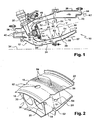
figure 1 est une demi-vue schématique en coupe axiale d'une chambre de combustion de turbomachine selon la technique antérieure ; - la
figure 2 est une vue schématique partielle en perspective des parois de la chambre de lafigure 1 ; - la
figure 3 est une demi-vue schématique en coupe axiale d'une chambre de combustion de turbomachine selon l'invention ; - la
figure 4 est une vue schématique partielle en perspective des parois de la chambre de lafigure 3 ; - la
figure 5 est une vue très schématique partielle d'une paroi de révolution d'une chambre selon l'invention, vue dans une direction radiale ; - les
figures 6 et 7 sont des vues correspondant à lafigure 5 et représentent des variantes de réalisation d'une paroi de chambre selon l'invention. - On se réfère d'abord à la
figure 1 qui représente une chambre annulaire de combustion 10 de turbomachine qui est agencée en sortie d'un diffuseur 12, lui même situé en sortie d'un compresseur, non représenté, et qui comprend des parois de révolution interne 14 et externe 16 reliées en amont par une paroi annulaire 18 de fond de chambre. Les parois 14, 16 de la chambre sont fixées en aval par des brides annulaires interne 20 et externe 22 respectivement sur un voile tronconique interne 24 du diffuseur, et sur une extrémité d'un carter externe 26 de la chambre, l'extrémité amont de ce carter 26 étant reliée à un voile tronconique externe 28 du diffuseur. - La paroi 18 de fond de chambre comporte des ouvertures 30 (
figures 1 et 2 ) à travers lesquelles passent de l'air provenant du diffuseur 12 et du carburant amené par des injecteurs 32 fixés sur le carter externe 26 et régulièrement répartis sur une circonférence autour de l'axe longitudinal 34 de la chambre. Chaque injecteur 32 comprend une tête 36 d'injection de carburant montée dans une ouverture 30 de la paroi annulaire 18 et alignée avec l'axe 38 de cette ouverture 30. - Une partie du débit d'air fourni par le compresseur et sortant du diffuseur 12 (flèches 40) passe par les ouvertures 30 et alimente la chambre de combustion 10 (flèches 42), l'autre partie du débit d'air alimentant des veines annulaires interne 44 et externe 46 de contournement de la chambre de combustion 10 (flèches 48).
- La veine interne 44 est formée entre le voile interne 24 du diffuseur 12 et la paroi interne 14 de la chambre, et l'air qui passe dans cette veine se partage en un débit 50 qui pénètre dans la chambre 10 par deux rangées d'orifices 52, 54 de la paroi interne 14 et en un débit 57 qui passe à travers des trous 58 de la bride interne 20 de la chambre pour aller refroidir des composants, non représentés, situés en aval de cette chambre.
- La veine externe 46 est formée entre le carter externe 26 et la paroi externe 16 de la chambre, et l'air qui passe dans cette veine se partage en un débit 60 qui pénètre dans la chambre 10 par deux rangées d'orifices 52, 54 de la paroi externe 16 et en un débit 62 qui passe à travers des trous 64 de la bride externe 22 pour aller refroidir des composants en aval.
- Les deux rangées d'orifices 52, 54 de chaque paroi 14, 16 de la chambre sont annulaires et distantes axialement l'une de l'autre, comme cela est bien visible aux
figures 1 et 2 . Les orifices 52 de la rangée annulaire amont sont des orifices d'entrée d'air primaire et fournissent à la chambre un débit d'air assurant une combustion stoechiométrique du carburant à l'intérieur de la chambre. Les orifices 54 de la rangée annulaire aval sont des orifices d'entrée d'air de dilution pour le refroidissement des gaz de combustion jusqu'à une température acceptable par la turbine de la turbomachine, montée en aval de la chambre et non représentée dans les dessins. - En outre, les parois 14, 16 de la chambre comportent des multiperforations (non visibles en
figure 1 et représentées schématiquement en 56 enfigure 2 ) servant au passage d'air de refroidissement de ces parois. - Le débit d'air passant par les orifices 52 d'air primaire et le débit d'air 42 passant par le système d'injection représentent chacun 15-25% du débit d'air 40 fourni par le diffuseur.
- Le débit d'air par les orifices 54 d'air de dilution est d'environ 20 à 30% et le débit d'air passant par les multiperforations 56 et par des orifices de refroidissement du fond de chambre 18 est d'environ 30 à 40% du débit total 40.
- L'invention permet de réduire de manière significative les émissions d'oxydes d'azote d'une chambre annulaire de combustion en supprimant le volume intermédiaire V compris entre les deux rangées annulaires d'orifices d'air primaire et d'air de dilution. Pour cela, la rangée aval d'orifices d'air de dilution est confondue avec la rangée amont d'orifices d'air primaire pour former une rangée unique dont les orifices servent à la fois à l'entrée d'air primaire et à l'entrée d'air de dilution.
- Dans l'exemple de réalisation de l'invention représenté aux
figures 3 et 4 , chaque paroi 14, 16 de la chambre comporte une seule rangée annulaire d'orifices d'entrée d'air primaire et d'air de dilution, ces orifices étant désignés par la même référence 66 car ils assurent chacun la double fonction d'alimentation de la chambre en air primaire et en air de dilution. - Les parois 14, 16 de la chambre comportent en outre des multiperforations 56 de passage d'air de refroidissement de ces parois.
- Le débit d'air passant par les orifices 66 représente environ 25 à 50%, de préférence 30 à 35%, et par exemple 32% du débit d'air 40 fourni par le diffuseur. Ce débit d'air comprend un débit d'air de dilution (20 à 30% environ) et un débit d'air primaire (2 à 12% environ). Le débit d'air 42 représente 30 à 40%, et par exemple 38% (ce débit comprenant environ 13 à 23% d'air primaire), du débit d'air 40 et le débit d'air de refroidissement du fond de chambre et d'air passant par les multiperforations 56 représente environ 30% du débit total.
- Le débit d'air (25-50%) passant à travers les orifices 66 est donc supérieur au débit d'air (15-25%) passant par les orifices 52 d'air primaire de la chambre de la technique antérieure, et le débit d'air 42 passant par le système d'injection (30-40%) est ici également supérieur au débit d'air 42 (15-25%) de la technique antérieure. L'augmentation du débit d'air passant par le système d'injection est favorable à la diminution des émissions d'oxydes d'azote, et l'augmentation du débit d'air passant par les orifices 66 permet de mieux maîtriser le profil de température vu par la turbine en sortie de la chambre de combustion.
- De plus, une partie du débit d'air primaire (environ 1/4 du débit total d'air primaire) passe à travers les orifices 66 et a pour but d'empêcher les zones de recirculation dans la chambre, et le reste du débit d'air primaire (représentant donc 3/4 du débit total d'air primaire) passe à travers les systèmes d'injection et à pour fonction d'alimenter en air la chambre.
- La position axiale de la rangée d'orifices 66 est de préférence située entre les positions axiales des rangées d'orifices 52, 54 de la technique antérieure. Cela permet de compenser la réduction du domaine de rallumage de la chambre, due à l'augmentation du débit d'air participant à la combustion dans la zone primaire de la chambre.
- Selon l'invention, la position axiale des orifices 66 sur chaque paroi est telle que la distance axiale L entre les axes des orifice 66 et des déflecteur 70 montés dans les ouvertures 30 de la paroi de fond de chambre 18 (mesurée le long de l'axe 38 d'une ouverture 30), est sensiblement égale à la moitié de la hauteur H de la zone primaire de combustion (
figure 3 ), c'est-à-dire à la distance entre les parois interne 14 et externe 16 de la chambre (mesurée dans un plan perpendiculaire à l'axe 38). - Les orifices 66 peuvent avoir une forme et/ou des dimensions identiques ou différentes les uns par rapport aux autres. Ils peuvent avoir une forme quelconque : circulaire, oblongue, etc. Leur diamètre est compris entre 5 et 20mm, et de préférence entre 10 et 15mm. Dans un exemple particulier de réalisation de l'invention, les orifices 66 de la paroi externe ont un diamètre de 14,5mm environ et ceux de la paroi interne ont un diamètre d'environ 12mm.
- Le nombre d'orifices 66 de chaque paroi 14, 16 peut être déterminé en fonction du nombre d'injecteurs 32 équipant la turbomachine. Le nombre d'orifices de chaque paroi 14, 16 est par exemple égal à k fois le nombre d'injecteurs, k étant égal à 2, 3 ou 4.
- On se réfère désormais aux
figures 5 à 7 qui représentent des variantes de réalisation des parois 14, 16 de la chambre selon l'invention. - Les paroi 14, 16 de la
figure 5 sont similaires à celles de l'exemple de réalisation desfigures 3 et 4 , et comprennent une rangée annulaire d'orifices 66 qui sont régulièrement répartis sur une circonférence centrée sur l'axe longitudinal 34 de la chambre. - Les orifices 66 sont situés dans un même plan sensiblement perpendiculaire à l'axe 34 de la chambre et sont alignés les uns avec les autres sur une ligne sensiblement circulaire. Lorsque la paroi 14, 16 est observée en direction radiale (depuis l'extérieur dans le cas de la paroi externe 16), cette ligne est sensiblement droite et perpendiculaire à l'axe 34 de la chambre.
- Dans la variante de réalisation de la
figure 6 , les orifices 66 sont situés sur une ligne courbe qui forme un arc de cercle sur la paroi, lorsque cette dernière est observée en direction radiale. Les orifices 66 représentés en traits continus sont situés sur une ligne courbe dont la concavité est orientée vers l'aval et les orifices représentés en traits discontinus sont situés sur une ligne courbe dont la concavité est orientée vers l'amont. La ligne sur laquelle les orifices 66 sont situés peut former des ondulations sur la paroi, sur tout le pourtour de celle-ci. - Les orifices 66 peuvent par exemple être disposés de façon à ce que les orifices les plus amont (ou les plus aval) soient alignés en direction axiale avec les injecteurs 32.
- Les orifices 66 de la variante de la
figure 7 diffèrent de ceux de lafigure 5 en ce que leur diamètre varie en fonction de leur position vis-à-vis des injecteurs 32. Les orifices 66 situés à proximité des injecteurs ont un diamètre supérieur à celui des autres orifices dans l'exemple représenté.
Claims (12)
- Chambre annulaire de combustion (10) d'une turbomachine, telle qu'un turboréacteur ou un turbopropulseur d'avion, comprenant des parois de révolution (14, 16) coaxiales s'étendant l'une à l'intérieur de l'autre et comportant des, orifices (66) d'entrée d'air primaire et des orifices (66) d'entrée d'air de dilution dans la chambre (30), les orifices (66) d'entrée d'air primaire et les orifices (66) d'entrée d'air de dilution de chaque paroi étant sensiblement alignés les uns avec les autres autour de l'axe longitudinal (34) de la chambre (10) et formant une seule rangée annulaire d'orifices (66) la chambre de combustion (10) comprenant une paroi de fond de chambre (18) reliant les extrémités amont des parois de révolution (14, 16) et comportant des ouvertures (30) dans lesquelles sont montés des systèmes (36) d'injection de carburant et des déflecteurs (70), caractérisée en ce que la distance (L) entre la rangée annulaires d'orifices (66) et le déflecteur (30) mesurée le long de l'axe (38) de l'ouverture correspondante (30) est sensiblement égale à la moitié de la hauteur (H) de la zone primaire de combustion dans la chambre (10).
- Chambre selon la revendication 1, caractérisée en ce que la rangée annulaire d'orifices (66) de chaque paroi (14, 16) est sensiblement circulaire.
- Chambre selon la revendication 1, caractérisée en ce que la rangée annulaire d'orifices (66) de chaque paroi de revolution (14, 16) est formée d'arcs de cercles ou d'ondulations.
- Chambre selon l'une des revendications précédentes, caractérisée en ce que les parois de revolution (14, 16) de la chambre (10) comportent en outre des multlperforations (56) pour le passage d'air de refroidissement.
- Chambre selon l'une des revendications précédentes, caractérisée en ce que la forme et/ou les dimensions des orifices (66) de chaque paroi de revolution (14, 16) sont sensiblement identiques.
- Chambre selon l'une des revendications 1 à 4, caractérisée en ce que la forme et/ou les dimensions des orifices (66) de chaque paroi de revolution (14, 16) diffèrent les unes des autres, en particulier en fonction de la position de ces orifices (66) par rapport à des systèmes (32) d'injection de carburant montés en amont de la chambre (10).
- Chambre selon l'une des revendications précédentes, caractérisée en ce que tes orifices (66) ont un diamètre compris entre 5 et 20mm, et de préférence entre 10 et 15mm.
- Chambre selon l'une des revendications précédentes, caractérisée en ce que le nombre d'orifices (66) de chaque paroi de revolution (14, 16) de la chambre (10) est égal à k fois le nombre de systèmes (32) d'injection de carburant montés en amont de la chambre (10), k étant égal à 2, 3 ou 4.
- Chambre selon l'une des revendications précédentes, caractérisée en ce que les systèmes d'injection (36) comprennent dés moyens d'alimentation en air de la chambre (10) avec une partie du débit d'air primaire destinée à pénétrer dans la chambre (10), l'autre partie du débit d'air primaire étant destinée à passer à travers les orifices (66) de chaque paroi de revolution (14, 16) de la chambre (10).
- Chambre selon l'une des revendications précédentes, caractérisée en ce que la chambre annulaire de combustion (10) est agencée en sortie d'un diffuseur (12) à travers lequel un air (40) comprenant un air primaire et un air de dilution peut circuler, les orifices (66) étant définis de manière à ce qu'un débit d'air passant à travers représente 25% à 50% du débit d'air (40) fourni par le diffuseur.
- Chambre selon la revendication 10, caractérisée en ce que les ouvertures (30) de la paroi de fond de chambre (18) sont définies de manière à ce qu'un débit d'air (42) passant à travers représente 30% à 40% du débit d'air (40) fourni par le diffuseur.
- Turbomachine, telle qu'un turboréacteur ou un turbopropulseur d'avion, caractérisée en ce qu'elle comprend Une chambre de combustion (10) selon l'une des revendications précédentes.
Applications Claiming Priority (2)
| Application Number | Priority Date | Filing Date | Title |
|---|---|---|---|
| FR0900221A FR2941287B1 (fr) | 2009-01-19 | 2009-01-19 | Paroi de chambre de combustion de turbomachine a une seule rangee annulaire d'orifices d'entree d'air primaire et de dilution |
| PCT/FR2009/001176 WO2010081941A1 (fr) | 2009-01-19 | 2009-10-01 | Paroi de chambre de combustion de turbomachine à une seule rangée annulaire d'orifices d'entrée d'air primaire et de dilution |
Publications (2)
| Publication Number | Publication Date |
|---|---|
| EP2379945A1 EP2379945A1 (fr) | 2011-10-26 |
| EP2379945B1 true EP2379945B1 (fr) | 2015-07-15 |
Family
ID=40668083
Family Applications (1)
| Application Number | Title | Priority Date | Filing Date |
|---|---|---|---|
| EP09752198.3A Not-in-force EP2379945B1 (fr) | 2009-01-19 | 2009-10-01 | Chambre annulaire de combustion de turbomachine à une seule rangée annulaire d'orifices d'entrée d'air primaire et de dilution |
Country Status (9)
| Country | Link |
|---|---|
| US (1) | US20110271678A1 (fr) |
| EP (1) | EP2379945B1 (fr) |
| JP (1) | JP2012515319A (fr) |
| CN (1) | CN102282423B (fr) |
| BR (1) | BRPI0924210A2 (fr) |
| CA (1) | CA2749632A1 (fr) |
| FR (1) | FR2941287B1 (fr) |
| RU (1) | RU2511778C2 (fr) |
| WO (1) | WO2010081941A1 (fr) |
Families Citing this family (20)
| Publication number | Priority date | Publication date | Assignee | Title |
|---|---|---|---|---|
| FR2943403B1 (fr) | 2009-03-17 | 2014-11-14 | Snecma | Chambre de combustion de turbomachine comprenant des moyens ameliores d'alimentation en air |
| US8910481B2 (en) * | 2009-05-15 | 2014-12-16 | United Technologies Corporation | Advanced quench pattern combustor |
| FR2950415B1 (fr) * | 2009-09-21 | 2011-10-14 | Snecma | Chambre de combustion de turbomachine aeronautique avec trous de combustion decales ou de debits differents |
| FR2958013B1 (fr) | 2010-03-26 | 2014-06-20 | Snecma | Chambre de combustion de turbomachine a compresseur centrifuge sans deflecteur |
| US8893382B2 (en) * | 2011-09-30 | 2014-11-25 | General Electric Company | Combustion system and method of assembling the same |
| EP2644995A1 (fr) * | 2012-03-27 | 2013-10-02 | Siemens Aktiengesellschaft | Agencement de trous amélioré de garnitures intérieures d'une chambre de combustion d'un moteur de turbine à gaz et dynamique de combustion à faibles émissions |
| JP6028578B2 (ja) * | 2013-01-15 | 2016-11-16 | 株式会社Ihi | 燃焼器 |
| UA118753C2 (uk) * | 2013-03-15 | 2019-03-11 | Презідент Енд Феллоуз Оф Гарвард Колледж | Пористі структури з повторюваною формою подовжених отворів |
| WO2014149081A1 (fr) * | 2013-03-15 | 2014-09-25 | Rolls-Royce Corporation | Chambre de combustion à doublet de contre-tourbillon |
| US10670267B2 (en) | 2015-08-14 | 2020-06-02 | Raytheon Technologies Corporation | Combustor hole arrangement for gas turbine engine |
| JP2017053523A (ja) * | 2015-09-08 | 2017-03-16 | 株式会社Ihi | ガスタービン用燃焼器 |
| FR3042023B1 (fr) * | 2015-10-06 | 2020-06-05 | Safran Helicopter Engines | Chambre de combustion annulaire pour turbomachine |
| US10816202B2 (en) | 2017-11-28 | 2020-10-27 | General Electric Company | Combustor liner for a gas turbine engine and an associated method thereof |
| FR3078384B1 (fr) * | 2018-02-28 | 2021-05-28 | Safran Aircraft Engines | Chambre de combustion a fond de chambre double |
| US11255543B2 (en) | 2018-08-07 | 2022-02-22 | General Electric Company | Dilution structure for gas turbine engine combustor |
| FR3094965B1 (fr) * | 2019-04-15 | 2022-01-07 | Crossject | Procédé optimisé de remplissage d’une charge pyrotechnique et système mettant en œuvre un tel procédé |
| GB202019222D0 (en) | 2020-12-07 | 2021-01-20 | Rolls Royce Plc | Lean burn combustor |
| GB202019219D0 (en) * | 2020-12-07 | 2021-01-20 | Rolls Royce Plc | Lean burn combustor |
| US12435877B2 (en) | 2023-02-20 | 2025-10-07 | General Electric Company | Gas turbine engine combustor with a set of dilution passages |
| WO2024248664A2 (fr) * | 2023-05-28 | 2024-12-05 | Владислав Викторович МАТАФОНОВ | Chambre de combustion de moteur à turbine à gaz |
Family Cites Families (11)
| Publication number | Priority date | Publication date | Assignee | Title |
|---|---|---|---|---|
| US5481867A (en) * | 1988-05-31 | 1996-01-09 | United Technologies Corporation | Combustor |
| SU1553795A1 (ru) * | 1988-06-20 | 1990-03-30 | Завод-Втуз При Производственном Объединении "Ленинградский Металлический Завод" | Кольцева камера сгорани |
| US5117636A (en) * | 1990-02-05 | 1992-06-02 | General Electric Company | Low nox emission in gas turbine system |
| FR2714154B1 (fr) * | 1993-12-22 | 1996-01-19 | Snecma | Chambre de combustion comportant une paroi munie d'une multiperforation. |
| FR2733582B1 (fr) * | 1995-04-26 | 1997-06-06 | Snecma | Chambre de combustion comportant une multiperforation d'inclinaison axiale et tangentielle variable |
| FR2748088B1 (fr) * | 1996-04-24 | 1998-05-29 | Snecma | Optimisation du melange de gaz brules dans une chambre de combustion annulaire |
| US6240731B1 (en) * | 1997-12-31 | 2001-06-05 | United Technologies Corporation | Low NOx combustor for gas turbine engine |
| US6178752B1 (en) * | 1998-03-24 | 2001-01-30 | United Technologies Corporation | Durability flame stabilizing fuel injector with impingement and transpiration cooled tip |
| US6606861B2 (en) * | 2001-02-26 | 2003-08-19 | United Technologies Corporation | Low emissions combustor for a gas turbine engine |
| US6675587B2 (en) * | 2002-03-21 | 2004-01-13 | United Technologies Corporation | Counter swirl annular combustor |
| US8161752B2 (en) * | 2008-11-20 | 2012-04-24 | Honeywell International Inc. | Combustors with inserts between dual wall liners |
-
2009
- 2009-01-19 FR FR0900221A patent/FR2941287B1/fr active Active
- 2009-10-01 CA CA2749632A patent/CA2749632A1/fr not_active Abandoned
- 2009-10-01 JP JP2011545772A patent/JP2012515319A/ja active Pending
- 2009-10-01 WO PCT/FR2009/001176 patent/WO2010081941A1/fr not_active Ceased
- 2009-10-01 US US13/144,794 patent/US20110271678A1/en not_active Abandoned
- 2009-10-01 RU RU2011134663/06A patent/RU2511778C2/ru not_active IP Right Cessation
- 2009-10-01 CN CN200980154984.6A patent/CN102282423B/zh not_active Expired - Fee Related
- 2009-10-01 BR BRPI0924210A patent/BRPI0924210A2/pt not_active IP Right Cessation
- 2009-10-01 EP EP09752198.3A patent/EP2379945B1/fr not_active Not-in-force
Also Published As
| Publication number | Publication date |
|---|---|
| WO2010081941A1 (fr) | 2010-07-22 |
| FR2941287B1 (fr) | 2011-03-25 |
| RU2011134663A (ru) | 2013-02-27 |
| CA2749632A1 (fr) | 2010-07-22 |
| EP2379945A1 (fr) | 2011-10-26 |
| BRPI0924210A2 (pt) | 2016-01-19 |
| JP2012515319A (ja) | 2012-07-05 |
| CN102282423B (zh) | 2014-06-18 |
| RU2511778C2 (ru) | 2014-04-10 |
| CN102282423A (zh) | 2011-12-14 |
| US20110271678A1 (en) | 2011-11-10 |
| FR2941287A1 (fr) | 2010-07-23 |
Similar Documents
| Publication | Publication Date | Title |
|---|---|---|
| EP2379945A1 (fr) | Paroi de chambre de combustion de turbomachine à une seule rangée annulaire d'orifices d'entrée d'air primaire et de dilution | |
| EP2710298B1 (fr) | Chambre annulaire de combustion pour une turbomachine | |
| EP2042806B1 (fr) | Chambre de combustion d'une turbomachine | |
| EP1857741B1 (fr) | Chambre de combustion d'une turbomachine | |
| EP1818613B1 (fr) | Chambre de combustion d'une turbomachine | |
| EP2334909B1 (fr) | Etanchéité entre une chambre de combustion et un distributeur de turbine dans une turbomachine | |
| EP1793168B1 (fr) | Dispositif d'injection d'un mélange d'air et de carburant, chambre de combustion et turbomachine munies d'un tel dispositif | |
| EP2012061B2 (fr) | Chambre de combustion d'un moteur à turbine à gaz | |
| EP2071242B1 (fr) | Système d'injection d'un mélange d'air et de carburant dans une chambre de combustion de turbomachine | |
| EP2071241B1 (fr) | Dispositif de guidage d'un élément dans un orifice d'une paroi de chambre de combustion de turbomachine | |
| EP1288579B1 (fr) | Chambre de combustion annulaire à double tête étagée | |
| FR2930591A1 (fr) | Optimisation du positionnement angulaire d'un distributeur de turbine en sortie d'une chambre de combustion de turbomachine | |
| FR2975465A1 (fr) | Paroi pour chambre de combustion de turbomachine comprenant un agencement optimise d'orifices d'entree d'air | |
| FR2975467A1 (fr) | Systeme d'injection de carburant pour une chambre de combustion de turbomachine | |
| FR2996286A1 (fr) | Dispositif d'injection pour une chambre de combustion de turbomachine | |
| FR2942640A1 (fr) | Chambre de post-combustion pour turbomachine | |
| WO2009144408A2 (fr) | Chambre de combustion annulaire de moteur a turbine a gaz | |
| CA2557944C (fr) | Chambre de combustion d'une turbomachine | |
| EP0718559B1 (fr) | Système d'injection d'une chambre de combustion à deux têtes | |
| EP0718560B1 (fr) | Chambre de combustion à deux têtes fonctionnant du ralenti au plein gaz | |
| FR2948749A1 (fr) | Systeme d'injection de carburant pour une chambre de combustion de turbomachine | |
| FR2996287A1 (fr) | Dispositif d'injection pour une chambre de combustion de turbomachine | |
| EP4004443B1 (fr) | Chambre de combustion comportant des systèmes d'injection secondaires et procédé d'alimentation en carburant | |
| FR2956725A1 (fr) | Systeme d'injection de carburant pour une chambre de combustion de turbomachine | |
| FR2975466A1 (fr) | Chambre annulaire de combustion pour une turbomachine |
Legal Events
| Date | Code | Title | Description |
|---|---|---|---|
| PUAI | Public reference made under article 153(3) epc to a published international application that has entered the european phase |
Free format text: ORIGINAL CODE: 0009012 |
|
| 17P | Request for examination filed |
Effective date: 20110719 |
|
| AK | Designated contracting states |
Kind code of ref document: A1 Designated state(s): AT BE BG CH CY CZ DE DK EE ES FI FR GB GR HR HU IE IS IT LI LT LU LV MC MK MT NL NO PL PT RO SE SI SK SM TR |
|
| RIN1 | Information on inventor provided before grant (corrected) |
Inventor name: CORTES, THIERRY, ANDRE, EMMANUEL Inventor name: BOURGOIS, SEBASTIEN, ALAIN, CHRISTOPHE Inventor name: COMMARET, PATRICE, ANDRE |
|
| DAX | Request for extension of the european patent (deleted) | ||
| 17Q | First examination report despatched |
Effective date: 20130507 |
|
| GRAP | Despatch of communication of intention to grant a patent |
Free format text: ORIGINAL CODE: EPIDOSNIGR1 |
|
| INTG | Intention to grant announced |
Effective date: 20141106 |
|
| GRAP | Despatch of communication of intention to grant a patent |
Free format text: ORIGINAL CODE: EPIDOSNIGR1 |
|
| INTG | Intention to grant announced |
Effective date: 20141208 |
|
| GRAP | Despatch of communication of intention to grant a patent |
Free format text: ORIGINAL CODE: EPIDOSNIGR1 |
|
| INTG | Intention to grant announced |
Effective date: 20150212 |
|
| GRAS | Grant fee paid |
Free format text: ORIGINAL CODE: EPIDOSNIGR3 |
|
| GRAA | (expected) grant |
Free format text: ORIGINAL CODE: 0009210 |
|
| AK | Designated contracting states |
Kind code of ref document: B1 Designated state(s): AT BE BG CH CY CZ DE DK EE ES FI FR GB GR HR HU IE IS IT LI LT LU LV MC MK MT NL NO PL PT RO SE SI SK SM TR |
|
| REG | Reference to a national code |
Ref country code: CH Ref legal event code: EP Ref country code: GB Ref legal event code: FG4D Free format text: NOT ENGLISH |
|
| REG | Reference to a national code |
Ref country code: IE Ref legal event code: FG4D Free format text: LANGUAGE OF EP DOCUMENT: FRENCH |
|
| REG | Reference to a national code |
Ref country code: AT Ref legal event code: REF Ref document number: 737004 Country of ref document: AT Kind code of ref document: T Effective date: 20150815 |
|
| REG | Reference to a national code |
Ref country code: DE Ref legal event code: R096 Ref document number: 602009032251 Country of ref document: DE |
|
| REG | Reference to a national code |
Ref country code: SE Ref legal event code: TRGR |
|
| REG | Reference to a national code |
Ref country code: AT Ref legal event code: MK05 Ref document number: 737004 Country of ref document: AT Kind code of ref document: T Effective date: 20150715 |
|
| REG | Reference to a national code |
Ref country code: NL Ref legal event code: MP Effective date: 20150715 |
|
| REG | Reference to a national code |
Ref country code: LT Ref legal event code: MG4D |
|
| PG25 | Lapsed in a contracting state [announced via postgrant information from national office to epo] |
Ref country code: LT Free format text: LAPSE BECAUSE OF FAILURE TO SUBMIT A TRANSLATION OF THE DESCRIPTION OR TO PAY THE FEE WITHIN THE PRESCRIBED TIME-LIMIT Effective date: 20150715 Ref country code: LV Free format text: LAPSE BECAUSE OF FAILURE TO SUBMIT A TRANSLATION OF THE DESCRIPTION OR TO PAY THE FEE WITHIN THE PRESCRIBED TIME-LIMIT Effective date: 20150715 Ref country code: NO Free format text: LAPSE BECAUSE OF FAILURE TO SUBMIT A TRANSLATION OF THE DESCRIPTION OR TO PAY THE FEE WITHIN THE PRESCRIBED TIME-LIMIT Effective date: 20151015 Ref country code: GR Free format text: LAPSE BECAUSE OF FAILURE TO SUBMIT A TRANSLATION OF THE DESCRIPTION OR TO PAY THE FEE WITHIN THE PRESCRIBED TIME-LIMIT Effective date: 20151016 Ref country code: FI Free format text: LAPSE BECAUSE OF FAILURE TO SUBMIT A TRANSLATION OF THE DESCRIPTION OR TO PAY THE FEE WITHIN THE PRESCRIBED TIME-LIMIT Effective date: 20150715 |
|
| PG25 | Lapsed in a contracting state [announced via postgrant information from national office to epo] |
Ref country code: PL Free format text: LAPSE BECAUSE OF FAILURE TO SUBMIT A TRANSLATION OF THE DESCRIPTION OR TO PAY THE FEE WITHIN THE PRESCRIBED TIME-LIMIT Effective date: 20150715 Ref country code: PT Free format text: LAPSE BECAUSE OF FAILURE TO SUBMIT A TRANSLATION OF THE DESCRIPTION OR TO PAY THE FEE WITHIN THE PRESCRIBED TIME-LIMIT Effective date: 20151116 Ref country code: HR Free format text: LAPSE BECAUSE OF FAILURE TO SUBMIT A TRANSLATION OF THE DESCRIPTION OR TO PAY THE FEE WITHIN THE PRESCRIBED TIME-LIMIT Effective date: 20150715 Ref country code: AT Free format text: LAPSE BECAUSE OF FAILURE TO SUBMIT A TRANSLATION OF THE DESCRIPTION OR TO PAY THE FEE WITHIN THE PRESCRIBED TIME-LIMIT Effective date: 20150715 Ref country code: ES Free format text: LAPSE BECAUSE OF FAILURE TO SUBMIT A TRANSLATION OF THE DESCRIPTION OR TO PAY THE FEE WITHIN THE PRESCRIBED TIME-LIMIT Effective date: 20150715 |
|
| REG | Reference to a national code |
Ref country code: DE Ref legal event code: R097 Ref document number: 602009032251 Country of ref document: DE |
|
| PG25 | Lapsed in a contracting state [announced via postgrant information from national office to epo] |
Ref country code: CZ Free format text: LAPSE BECAUSE OF FAILURE TO SUBMIT A TRANSLATION OF THE DESCRIPTION OR TO PAY THE FEE WITHIN THE PRESCRIBED TIME-LIMIT Effective date: 20150715 Ref country code: EE Free format text: LAPSE BECAUSE OF FAILURE TO SUBMIT A TRANSLATION OF THE DESCRIPTION OR TO PAY THE FEE WITHIN THE PRESCRIBED TIME-LIMIT Effective date: 20150715 Ref country code: DK Free format text: LAPSE BECAUSE OF FAILURE TO SUBMIT A TRANSLATION OF THE DESCRIPTION OR TO PAY THE FEE WITHIN THE PRESCRIBED TIME-LIMIT Effective date: 20150715 Ref country code: SK Free format text: LAPSE BECAUSE OF FAILURE TO SUBMIT A TRANSLATION OF THE DESCRIPTION OR TO PAY THE FEE WITHIN THE PRESCRIBED TIME-LIMIT Effective date: 20150715 |
|
| REG | Reference to a national code |
Ref country code: DE Ref legal event code: R119 Ref document number: 602009032251 Country of ref document: DE |
|
| PLBE | No opposition filed within time limit |
Free format text: ORIGINAL CODE: 0009261 |
|
| STAA | Information on the status of an ep patent application or granted ep patent |
Free format text: STATUS: NO OPPOSITION FILED WITHIN TIME LIMIT |
|
| PG25 | Lapsed in a contracting state [announced via postgrant information from national office to epo] |
Ref country code: LU Free format text: LAPSE BECAUSE OF FAILURE TO SUBMIT A TRANSLATION OF THE DESCRIPTION OR TO PAY THE FEE WITHIN THE PRESCRIBED TIME-LIMIT Effective date: 20151001 Ref country code: RO Free format text: LAPSE BECAUSE OF FAILURE TO SUBMIT A TRANSLATION OF THE DESCRIPTION OR TO PAY THE FEE WITHIN THE PRESCRIBED TIME-LIMIT Effective date: 20150715 |
|
| REG | Reference to a national code |
Ref country code: SE Ref legal event code: EUG Ref country code: CH Ref legal event code: PL |
|
| 26N | No opposition filed |
Effective date: 20160418 |
|
| GBPC | Gb: european patent ceased through non-payment of renewal fee |
Effective date: 20151015 |
|
| PG25 | Lapsed in a contracting state [announced via postgrant information from national office to epo] |
Ref country code: MC Free format text: LAPSE BECAUSE OF FAILURE TO SUBMIT A TRANSLATION OF THE DESCRIPTION OR TO PAY THE FEE WITHIN THE PRESCRIBED TIME-LIMIT Effective date: 20150715 Ref country code: IS Free format text: LAPSE BECAUSE OF FAILURE TO SUBMIT A TRANSLATION OF THE DESCRIPTION OR TO PAY THE FEE WITHIN THE PRESCRIBED TIME-LIMIT Effective date: 20150715 |
|
| REG | Reference to a national code |
Ref country code: IE Ref legal event code: MM4A |
|
| PG25 | Lapsed in a contracting state [announced via postgrant information from national office to epo] |
Ref country code: LI Free format text: LAPSE BECAUSE OF NON-PAYMENT OF DUE FEES Effective date: 20151031 Ref country code: DE Free format text: LAPSE BECAUSE OF NON-PAYMENT OF DUE FEES Effective date: 20160503 Ref country code: GB Free format text: LAPSE BECAUSE OF NON-PAYMENT OF DUE FEES Effective date: 20151015 Ref country code: CH Free format text: LAPSE BECAUSE OF NON-PAYMENT OF DUE FEES Effective date: 20151031 |
|
| REG | Reference to a national code |
Ref country code: FR Ref legal event code: ST Effective date: 20160630 |
|
| PG25 | Lapsed in a contracting state [announced via postgrant information from national office to epo] |
Ref country code: SE Free format text: LAPSE BECAUSE OF NON-PAYMENT OF DUE FEES Effective date: 20151002 Ref country code: FR Free format text: LAPSE BECAUSE OF NON-PAYMENT OF DUE FEES Effective date: 20151102 Ref country code: SI Free format text: LAPSE BECAUSE OF FAILURE TO SUBMIT A TRANSLATION OF THE DESCRIPTION OR TO PAY THE FEE WITHIN THE PRESCRIBED TIME-LIMIT Effective date: 20150715 |
|
| PG25 | Lapsed in a contracting state [announced via postgrant information from national office to epo] |
Ref country code: IE Free format text: LAPSE BECAUSE OF NON-PAYMENT OF DUE FEES Effective date: 20151001 |
|
| PG25 | Lapsed in a contracting state [announced via postgrant information from national office to epo] |
Ref country code: IT Free format text: LAPSE BECAUSE OF NON-PAYMENT OF DUE FEES Effective date: 20151001 |
|
| PG25 | Lapsed in a contracting state [announced via postgrant information from national office to epo] |
Ref country code: HU Free format text: LAPSE BECAUSE OF FAILURE TO SUBMIT A TRANSLATION OF THE DESCRIPTION OR TO PAY THE FEE WITHIN THE PRESCRIBED TIME-LIMIT; INVALID AB INITIO Effective date: 20091001 Ref country code: SM Free format text: LAPSE BECAUSE OF FAILURE TO SUBMIT A TRANSLATION OF THE DESCRIPTION OR TO PAY THE FEE WITHIN THE PRESCRIBED TIME-LIMIT Effective date: 20150715 Ref country code: BG Free format text: LAPSE BECAUSE OF FAILURE TO SUBMIT A TRANSLATION OF THE DESCRIPTION OR TO PAY THE FEE WITHIN THE PRESCRIBED TIME-LIMIT Effective date: 20150715 |
|
| PG25 | Lapsed in a contracting state [announced via postgrant information from national office to epo] |
Ref country code: CY Free format text: LAPSE BECAUSE OF FAILURE TO SUBMIT A TRANSLATION OF THE DESCRIPTION OR TO PAY THE FEE WITHIN THE PRESCRIBED TIME-LIMIT Effective date: 20150715 Ref country code: NL Free format text: LAPSE BECAUSE OF FAILURE TO SUBMIT A TRANSLATION OF THE DESCRIPTION OR TO PAY THE FEE WITHIN THE PRESCRIBED TIME-LIMIT Effective date: 20150715 |
|
| PG25 | Lapsed in a contracting state [announced via postgrant information from national office to epo] |
Ref country code: BE Free format text: LAPSE BECAUSE OF NON-PAYMENT OF DUE FEES Effective date: 20151031 |
|
| PG25 | Lapsed in a contracting state [announced via postgrant information from national office to epo] |
Ref country code: TR Free format text: LAPSE BECAUSE OF FAILURE TO SUBMIT A TRANSLATION OF THE DESCRIPTION OR TO PAY THE FEE WITHIN THE PRESCRIBED TIME-LIMIT Effective date: 20150715 Ref country code: MT Free format text: LAPSE BECAUSE OF FAILURE TO SUBMIT A TRANSLATION OF THE DESCRIPTION OR TO PAY THE FEE WITHIN THE PRESCRIBED TIME-LIMIT Effective date: 20150715 |
|
| PG25 | Lapsed in a contracting state [announced via postgrant information from national office to epo] |
Ref country code: MK Free format text: LAPSE BECAUSE OF FAILURE TO SUBMIT A TRANSLATION OF THE DESCRIPTION OR TO PAY THE FEE WITHIN THE PRESCRIBED TIME-LIMIT Effective date: 20150715 |