EP2379882B1 - Turbine power plant - Google Patents
Turbine power plant Download PDFInfo
- Publication number
- EP2379882B1 EP2379882B1 EP09759685.2A EP09759685A EP2379882B1 EP 2379882 B1 EP2379882 B1 EP 2379882B1 EP 09759685 A EP09759685 A EP 09759685A EP 2379882 B1 EP2379882 B1 EP 2379882B1
- Authority
- EP
- European Patent Office
- Prior art keywords
- generator
- continuous
- transmission
- rotor
- power installation
- Prior art date
- Legal status (The legal status is an assumption and is not a legal conclusion. Google has not performed a legal analysis and makes no representation as to the accuracy of the status listed.)
- Active
Links
- 230000005540 biological transmission Effects 0.000 claims description 51
- 238000009434 installation Methods 0.000 claims description 21
- 230000001360 synchronised effect Effects 0.000 claims description 15
- 230000003068 static effect Effects 0.000 claims description 9
- 238000006243 chemical reaction Methods 0.000 claims description 8
- 239000012530 fluid Substances 0.000 claims description 6
- 238000005452 bending Methods 0.000 claims description 3
- 238000004378 air conditioning Methods 0.000 claims description 2
- 238000001816 cooling Methods 0.000 claims description 2
- 230000004308 accommodation Effects 0.000 claims 5
- 238000004519 manufacturing process Methods 0.000 claims 1
- 230000008878 coupling Effects 0.000 description 7
- 238000010168 coupling process Methods 0.000 description 7
- 238000005859 coupling reaction Methods 0.000 description 7
- 230000008901 benefit Effects 0.000 description 5
- 238000010276 construction Methods 0.000 description 5
- 238000013461 design Methods 0.000 description 5
- 238000012423 maintenance Methods 0.000 description 5
- 239000000463 material Substances 0.000 description 5
- 238000012986 modification Methods 0.000 description 4
- 230000004048 modification Effects 0.000 description 4
- 239000012050 conventional carrier Substances 0.000 description 2
- 238000013016 damping Methods 0.000 description 2
- 230000005284 excitation Effects 0.000 description 2
- 230000001681 protective effect Effects 0.000 description 2
- 206010001497 Agitation Diseases 0.000 description 1
- 241000555745 Sciuridae Species 0.000 description 1
- 230000009471 action Effects 0.000 description 1
- 238000013459 approach Methods 0.000 description 1
- 150000001875 compounds Chemical class 0.000 description 1
- 230000007423 decrease Effects 0.000 description 1
- 230000001419 dependent effect Effects 0.000 description 1
- 238000011161 development Methods 0.000 description 1
- 230000008030 elimination Effects 0.000 description 1
- 238000003379 elimination reaction Methods 0.000 description 1
- 230000004907 flux Effects 0.000 description 1
- 230000002706 hydrostatic effect Effects 0.000 description 1
- 238000003780 insertion Methods 0.000 description 1
- 230000037431 insertion Effects 0.000 description 1
- 230000010354 integration Effects 0.000 description 1
- 239000007788 liquid Substances 0.000 description 1
- 238000004513 sizing Methods 0.000 description 1
- 239000002887 superconductor Substances 0.000 description 1
- 238000012549 training Methods 0.000 description 1
- 238000013519 translation Methods 0.000 description 1
- 238000011144 upstream manufacturing Methods 0.000 description 1
- 239000013585 weight reducing agent Substances 0.000 description 1
- 238000004804 winding Methods 0.000 description 1
Images

Classifications
-
- F—MECHANICAL ENGINEERING; LIGHTING; HEATING; WEAPONS; BLASTING
- F03—MACHINES OR ENGINES FOR LIQUIDS; WIND, SPRING, OR WEIGHT MOTORS; PRODUCING MECHANICAL POWER OR A REACTIVE PROPULSIVE THRUST, NOT OTHERWISE PROVIDED FOR
- F03D—WIND MOTORS
- F03D13/00—Assembly, mounting or commissioning of wind motors; Arrangements specially adapted for transporting wind motor components
- F03D13/20—Arrangements for mounting or supporting wind motors; Masts or towers for wind motors
-
- F—MECHANICAL ENGINEERING; LIGHTING; HEATING; WEAPONS; BLASTING
- F03—MACHINES OR ENGINES FOR LIQUIDS; WIND, SPRING, OR WEIGHT MOTORS; PRODUCING MECHANICAL POWER OR A REACTIVE PROPULSIVE THRUST, NOT OTHERWISE PROVIDED FOR
- F03D—WIND MOTORS
- F03D13/00—Assembly, mounting or commissioning of wind motors; Arrangements specially adapted for transporting wind motor components
- F03D13/10—Assembly of wind motors; Arrangements for erecting wind motors
-
- F—MECHANICAL ENGINEERING; LIGHTING; HEATING; WEAPONS; BLASTING
- F03—MACHINES OR ENGINES FOR LIQUIDS; WIND, SPRING, OR WEIGHT MOTORS; PRODUCING MECHANICAL POWER OR A REACTIVE PROPULSIVE THRUST, NOT OTHERWISE PROVIDED FOR
- F03D—WIND MOTORS
- F03D15/00—Transmission of mechanical power
-
- F—MECHANICAL ENGINEERING; LIGHTING; HEATING; WEAPONS; BLASTING
- F03—MACHINES OR ENGINES FOR LIQUIDS; WIND, SPRING, OR WEIGHT MOTORS; PRODUCING MECHANICAL POWER OR A REACTIVE PROPULSIVE THRUST, NOT OTHERWISE PROVIDED FOR
- F03D—WIND MOTORS
- F03D9/00—Adaptations of wind motors for special use; Combinations of wind motors with apparatus driven thereby; Wind motors specially adapted for installation in particular locations
- F03D9/20—Wind motors characterised by the driven apparatus
- F03D9/25—Wind motors characterised by the driven apparatus the apparatus being an electrical generator
-
- F—MECHANICAL ENGINEERING; LIGHTING; HEATING; WEAPONS; BLASTING
- F03—MACHINES OR ENGINES FOR LIQUIDS; WIND, SPRING, OR WEIGHT MOTORS; PRODUCING MECHANICAL POWER OR A REACTIVE PROPULSIVE THRUST, NOT OTHERWISE PROVIDED FOR
- F03D—WIND MOTORS
- F03D80/00—Details, components or accessories not provided for in groups F03D1/00 - F03D17/00
- F03D80/70—Bearing or lubricating arrangements
-
- F—MECHANICAL ENGINEERING; LIGHTING; HEATING; WEAPONS; BLASTING
- F05—INDEXING SCHEMES RELATING TO ENGINES OR PUMPS IN VARIOUS SUBCLASSES OF CLASSES F01-F04
- F05B—INDEXING SCHEME RELATING TO WIND, SPRING, WEIGHT, INERTIA OR LIKE MOTORS, TO MACHINES OR ENGINES FOR LIQUIDS COVERED BY SUBCLASSES F03B, F03D AND F03G
- F05B2230/00—Manufacture
- F05B2230/50—Building or constructing in particular ways
-
- F—MECHANICAL ENGINEERING; LIGHTING; HEATING; WEAPONS; BLASTING
- F05—INDEXING SCHEMES RELATING TO ENGINES OR PUMPS IN VARIOUS SUBCLASSES OF CLASSES F01-F04
- F05B—INDEXING SCHEME RELATING TO WIND, SPRING, WEIGHT, INERTIA OR LIKE MOTORS, TO MACHINES OR ENGINES FOR LIQUIDS COVERED BY SUBCLASSES F03B, F03D AND F03G
- F05B2230/00—Manufacture
- F05B2230/60—Assembly methods
-
- F—MECHANICAL ENGINEERING; LIGHTING; HEATING; WEAPONS; BLASTING
- F05—INDEXING SCHEMES RELATING TO ENGINES OR PUMPS IN VARIOUS SUBCLASSES OF CLASSES F01-F04
- F05B—INDEXING SCHEME RELATING TO WIND, SPRING, WEIGHT, INERTIA OR LIKE MOTORS, TO MACHINES OR ENGINES FOR LIQUIDS COVERED BY SUBCLASSES F03B, F03D AND F03G
- F05B2240/00—Components
- F05B2240/10—Stators
- F05B2240/14—Casings, housings, nacelles, gondels or the like, protecting or supporting assemblies there within
-
- F—MECHANICAL ENGINEERING; LIGHTING; HEATING; WEAPONS; BLASTING
- F05—INDEXING SCHEMES RELATING TO ENGINES OR PUMPS IN VARIOUS SUBCLASSES OF CLASSES F01-F04
- F05B—INDEXING SCHEME RELATING TO WIND, SPRING, WEIGHT, INERTIA OR LIKE MOTORS, TO MACHINES OR ENGINES FOR LIQUIDS COVERED BY SUBCLASSES F03B, F03D AND F03G
- F05B2240/00—Components
- F05B2240/50—Bearings
-
- Y—GENERAL TAGGING OF NEW TECHNOLOGICAL DEVELOPMENTS; GENERAL TAGGING OF CROSS-SECTIONAL TECHNOLOGIES SPANNING OVER SEVERAL SECTIONS OF THE IPC; TECHNICAL SUBJECTS COVERED BY FORMER USPC CROSS-REFERENCE ART COLLECTIONS [XRACs] AND DIGESTS
- Y02—TECHNOLOGIES OR APPLICATIONS FOR MITIGATION OR ADAPTATION AGAINST CLIMATE CHANGE
- Y02E—REDUCTION OF GREENHOUSE GAS [GHG] EMISSIONS, RELATED TO ENERGY GENERATION, TRANSMISSION OR DISTRIBUTION
- Y02E10/00—Energy generation through renewable energy sources
- Y02E10/70—Wind energy
- Y02E10/72—Wind turbines with rotation axis in wind direction
-
- Y—GENERAL TAGGING OF NEW TECHNOLOGICAL DEVELOPMENTS; GENERAL TAGGING OF CROSS-SECTIONAL TECHNOLOGIES SPANNING OVER SEVERAL SECTIONS OF THE IPC; TECHNICAL SUBJECTS COVERED BY FORMER USPC CROSS-REFERENCE ART COLLECTIONS [XRACs] AND DIGESTS
- Y02—TECHNOLOGIES OR APPLICATIONS FOR MITIGATION OR ADAPTATION AGAINST CLIMATE CHANGE
- Y02E—REDUCTION OF GREENHOUSE GAS [GHG] EMISSIONS, RELATED TO ENERGY GENERATION, TRANSMISSION OR DISTRIBUTION
- Y02E10/00—Energy generation through renewable energy sources
- Y02E10/70—Wind energy
- Y02E10/728—Onshore wind turbines
-
- Y—GENERAL TAGGING OF NEW TECHNOLOGICAL DEVELOPMENTS; GENERAL TAGGING OF CROSS-SECTIONAL TECHNOLOGIES SPANNING OVER SEVERAL SECTIONS OF THE IPC; TECHNICAL SUBJECTS COVERED BY FORMER USPC CROSS-REFERENCE ART COLLECTIONS [XRACs] AND DIGESTS
- Y02—TECHNOLOGIES OR APPLICATIONS FOR MITIGATION OR ADAPTATION AGAINST CLIMATE CHANGE
- Y02P—CLIMATE CHANGE MITIGATION TECHNOLOGIES IN THE PRODUCTION OR PROCESSING OF GOODS
- Y02P70/00—Climate change mitigation technologies in the production process for final industrial or consumer products
- Y02P70/50—Manufacturing or production processes characterised by the final manufactured product
Definitions
- the present invention relates to a flow power plant for converting mechanical energy into another form of energy, preferably electrical energy.
- the invention will be described with reference to a wind turbine which converts the energy of an air flow into electrical energy. It should be understood, however, that the invention may be practiced with other types of power converters or power plants such as wave or tidal, hydroelectric power plants.
- Wind turbines are known in which a gondola is rotatably mounted on a tower.
- a stable carrier plate or a carrier frame accommodates the individual components of the drive train - eg rotor bearing, rotor shaft, gearbox, generator - and transfers their static and dynamic loads to the tower.
- the carrier plate simultaneously forms the lower part of the nacelle, which surrounds the drive train in the form of a protective housing.
- the support plate is designed very stable, since it must support, for example, a rotor torque in the order of 100,000 Nm or more for plant performance in the megawatt range.
- This construction using a carrier plate is for example in the DE 1184567 A2 or the EP 1 251 306 A2 shown.
- L-shaped support frames are eg in the DE 29609794 U1 shown.
- the EP 1 046 140 A2 shows a wind turbine, in which a foot is formed on the azimuth bearing of the tower. At this foot a generator or a transmission are mounted. Other components, such as bearings, gearbox or generator are attached to the foot-mounted component.
- the EP 1 243 791 A2 shows a wind turbine with a machine frame, are mounted on the bearing or transmission components. A generator is flanged to the gearbox components.
- the US 2 655 604 A shows a wind turbine in which a housing of a transmission is provided with a projection which receives an azimuth bearing. To the gearbox a generator is flanged.
- the flow force plant according to the invention for generating electrical energy from a fluid flow i. a gas flow or liquid flow
- a fluid flow i. a gas flow or liquid flow
- a base in particular a tower, rotatably mounted nacelle, which comprises a drive train which is driven by a rotor, which is driven by the fluid flow, and by means of functional components for supporting the rotor and / or Storage of the transmission and / or are designed for energy conversion, which converts the rotor registered energy of the fluid flow into electrical energy.
- the peculiarity is that at least one of said functional components represents a reliable connection for the transmission of static and dynamic loads from the drive train to the tower.
- a structure which is required anyway a double function it thus serves e.g. a functional component such as e.g. a gearbox - or its housing - both as a functional component and as a load-bearing element for the introduction of force or power transmission of static and dynamic loads directly into the tower.
- a functional component such as e.g. a gearbox - or its housing - both as a functional component and as a load-bearing element for the introduction of force or power transmission of static and dynamic loads directly into the tower.
- Any required nacelle structure can be made easier due to the use of the housing structure of a functional component or their mass. It decreases the weight of tower head or nacelle, or you get a more stable gondola with comparable mass.
- the conventional carrier plate or the conventional support frame can be omitted or substantially lighter dimensions.
- a support ring of an azimuth bearing is provided with a type of receiving shell, which can carry at least the static weight of the individual functional components.
- the receiving tray facilitates the maintenance and installation case, the provisional arrangement and positioning of the functional components.
- the at least one functional component is attached to a support ring structure of an azimuth bearing.
- the functional components on which the highest, in particular dynamic, loads are to be supported for example the rotor bearing which predominantly carries the thrust load of the rotor and the gear on which the main part of the rotor torque is supported, can be fastened to the support ring structure of the azimuth bearing.
- the support ring structure is seen as part of the azimuth bearing and does not extend significantly beyond the bearing in its radial circumference. She does not own either extending over the entire nacelle, in particular horizontally elongated extension, which has a conventional carrier plate for receiving all the functional components of the drive train.
- the housings of the functional components preferably serve to support the loads on the tower. Further savings in material and weight can be achieved if a further functional component is attached to the housing of such a functional component, so that its load is likewise supported on the tower via said housing.
- a relatively light support frame for receiving additional components, e.g. a frequency converter, transformer, fire protection system, control electronics, emergency power source, cooling system or air conditioning system.
- additional components e.g. a frequency converter, transformer, fire protection system, control electronics, emergency power source, cooling system or air conditioning system.
- a ring generator In a header bearing, a ring generator can be arranged, which on the one hand supports its torque itself or on the attachment bearing on the tower, and on the other hand absorbs or damps some of the load or power peaks already on the input side of the drive train. This relieves downstream functional components of the powertrain, such as the gearbox or generator, and may possibly be dimensioned for lower overload.
- This object is considered in connection with a wind turbine without the restriction of the use of a functional component as a load connection to the tower as an independent invention.
- a transmission with high gear ratio e.g. 1:60 to 1: 140 with an asynchronous generator.
- the generator could according to the invention e.g. be attached to the gear housing without using a support plate.
- the relatively low compared to the transmission attacking the generator and supported on the gear housing in this case torque requires no appreciable increase in weight of the generator housing.
- a synchronous generator can also be used here.
- the forces and moments that come through the wind and the reaction of the electrical network, via the rotor bearing and the azimuth bearing or via the transmission and the azimuth bearing are introduced directly into the tower.
- the advantage here is, inter alia, that e.g. the bearing seat or the bearing shell of the rotor bearing is part of the nacelle and therefore simplifies the nacelle structure or on an additional nacelle structure -. a heavy base plate - can be omitted partially or completely.
- the bearing receptacle is part of the housing structure, then this bearing receptacle or the bearing itself can advantageously be designed so that this has a sufficiently high rigidity with as little use of material as possible. This could be achieved by a cylinder structure or the like of the bearing shell or the bearing, whereby this receives a very high moment of area moment of inertia.
- mainshaft bearing is a 2-point bearing to minimize bending moments and misalignment in the gearbox.
- bearing moment bearing or other types can be used.
- a first embodiment is in the FIG. 1 represents.
- the tower head section of a wind turbine 1 comprises, inter alia, at the upper tower section 3, an azimuth bearing 5 via which the nacelle 7 or the drive train is rotatable on Tower section 3 is mounted.
- the term nacelle 7 should, with the exception of the rotor 9 on all turmabseits the azimuth bearing 5 arranged components
- the driven train comprised by the nacelle 7 comprises, as functional components, a rotor 9 with rotor blades which may be adjustable in pitch angle, a rotor shaft 11 which is rotatably mounted in a rotor bearing 13, a transmission gear 15, a generator 17 connected to the transmission gear 15, and others Auxiliary components such as a frequency converter 19 for controlling the generator 17 and the feed, braking units, a hydraulic system, and a higher-level control electronics 21, which controls the wind turbine 1.
- the rotor bearing 13 is attached to a support ring 25 of the azimuth bearing 5. It transmits, above all, thrust and torsion loads as well as static weight forces on the support ring 25 and thus on the tower.
- the gear 15 is flanged.
- the gear 15 is supported on the support ring 25, whereby the high torque acting on the gear 15 torques are introduced into the tower.
- the generator 17 is flanged to the transmission housing. This generally withstands the low torque occurring on the generator without additional sizing.
- a frame-like support structure 23 may be attached, which provides a light mounting platform for the auxiliary components 19 and 21.
- the rotor shaft 11 is mounted in the rotor bearing 13 at two points. Due to the two-point bearing at least the static loads of rotor 9 and rotor shaft 11 can be supported in the rotor bearing 13, so that other components, such as the transmission are easily replaceable.
- the integration of the bearings is done in or on a structure - see also "housing of the rotor bearing 13" - with the highest possible moment of inertia to achieve sufficient rigidity with little use of materials.
- the bearings used can be designed as ball, cylindrical or tapered roller bearings and as plain bearings. In this type of storage, the bending loads of the rotor shaft, which are caused by the wind forces are largely not passed into the transmission, which brings significant advantages in the construction of this.
- connection of the gear housing with the structure of the bearing of the rotor shaft 11 can be done by means of screws, bolts and other elements that are able The corresponding forces and moments have to be transmitted.
- the connection of the rotor shaft with the transmission input shaft can take place with the aid of various couplings (rigid or elastic, for example, with gear couplings).
- the generator shaft can be mounted either directly or via a rigid or elastic, possibly torsional vibration damping coupling.
- the housing of the generator can be connected directly to the transmission housing here. These compounds have the task to take over the forces and moments between the gearbox and generator.
- the shaft of the generator can be designed so that the operating and / or holding brake 18 or the brake system is mounted thereon. For the support of the weight, it is conceivable that the gearbox and / or the generator are still supported on a support structure to be additionally attached.
- the reliable connection of the bearing housing, the gearbox and the generator and their connection can be realized by the axial connections described.
- a possible modification of the embodiment presented is that the operating and / or holding brake or the brake system is mounted between the transmission and the generator. .
- a second embodiment is in the FIG. 2 represents.
- the wind turbine 1 according to the second embodiment largely corresponds to the wind turbine 1 according to the first embodiment.
- the modifications to the first exemplary embodiment described below relate above all to the mechanical construction and the connection of the components of the drive train of the nacelle 7 'with respect to the nacelle 7.
- a torque bearing 13 ' is provided, in which the rotor shaft 11 is supported in a bearing point.
- the moment bearing 13 ' also supports tilting moments of the rotor shaft 11.
- the moment bearing 13 ' is attached to the support ring 25.
- the gear 15 ' is also attached to the support ring 25. It is preferably decoupled from tilting movements of the rotor shaft 11, for example by a gimbal connection between Rotor shaft 11 and input shaft of the transmission 15 '.
- the moment bearing 13 'and the gear 15' are fastened to each other.
- the generator 17 is flanged.
- the attachment of the other components corresponds to that shown in the first embodiment.
- the overall length of the drive train is shortened compared to the first embodiment. This will result in a more compact and lighter gondola.
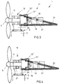
- a third embodiment is in the FIG. 3 represents.
- the wind turbine 1 according to the third embodiment largely corresponds to the wind turbine 1 according to the first embodiment.
- the modifications described below with respect to the first embodiment relate above all to the mechanical structure and the connection of the components of the drive train of the nacelle 7 "relative to the nacelle 7.
- the rotor shaft 11 is supported in the bearing 13 at two axially spaced bearings.
- the bearing 13 is attached to the support ring 25.
- a gearbox 15 " which is connected on the one hand to the support ring 25 and on the other hand to a housing structure of the bearing 13, is connected to the bearing 13, comparable to the first exemplary embodiment
- the generator 17" is attached to the gearbox 15 "or its housing Stator of the generator 17 “is mechanically connected to the transmission housing.
- the generator 17 " is designed as a ring generator
- the free interior of the generator 17” accommodates a section of the gear 17 ", which can shorten the overall length of the power take-off train or gondola 7". In order to avoid costly contacting of the rotor of the generator 17 ", this could be permanently excited, but hybrid-excited or externally excited generator designs in a ring structure are also possible.
- FIG. 4 serves to explain a fourth embodiment, which is a minor modification of the third embodiment.
- a directly driven by the rotor shaft 11 generator 27 is provided in the bearing 13 between the two bearings.
- the generator 27 converts a portion of the mechanical energy introduced at the rotor 9 directly into electrical energy. Only the energy not removed at the generator 27 is introduced into the transmission 15 ", the transmission 15" also has only a smaller one Support reaction torque, since a part of the voltage applied to the rotor 9 torque is already derived by the generator 27.
- first and the second embodiment in the sense of the fourth embodiment are modifiable, i. Even with the gondolas 7 and 7 ', a generator driven directly by the rotor shaft 11 can be integrated with the bearing 13 or 13'.
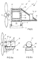
- FIG. 5 serves to explain a fifth embodiment.
- the fifth embodiment represents a further variant of the embodiments described above.
- the gear 15"' in the housing of a generator 17 "'fully integrated, ie the housing of the generator 17"' surrounds the Gear 15 '"radially and axially .
- the generator 17'" is fixed with its housing on the support ring 25 of the azimuth bearing 5.
- a stationary component of the gearbox 15 "is fixed to the generator housing by means of a shaft 31 or optionally via a hollow shaft 13.
- the reaction shaft of the gearbox 15 '" is supported on the generator housing and thus on the support ring 25 via the stationary shaft 31.
- the transmission 15 '' is, for example, a single-stage planetary gear which is designed to translate the rotational speed of the rotor shaft 11 by a factor of 6 to 60.
- the gear 15 '" has a casing-like or bell-shaped casing 33, which surrounds the rotor 35 of the generator 17 "'carries or has the function of the rotor 35.
- the stator 37 of the generator 17'" is arranged in the generator housing.
- the generator housing can serve as a nacelle housing or as part of the nacelle housing and thus a weather protection of the components arranged in the transmission housing guarantee.
- the transmission 15 "' be designed as a multi-stage planetary gear.
- the support ring 25 is provided with a kind of receiving tray, which can carry at least the static weight of the individual functional components.
- a moment bearing 13 'and a gear 15' are used in the receiving tray 40.
- the auxiliary components such as a frequency converter 19 for controlling the generator 17 and the feed, braking units, a hydraulic system, and a higher-level control electronics 21 may be arranged in the receiving shell.
- additional fastening means 42 such as bolts, supports, screws, etc., after insertion of the functional components in this receiving tray 40, a connection with the receiving tray 40 itself and with the support ring 25.
- the functional components are fastened to each other by fastening means 43.
- the receiving tray 40 facilitates doing in maintenance and installation the provisional arrangement and positioning of the functional components 13 ', 15' and 17. Since only small loads occur on the generator 17, it may be sufficient to attach it only to the receiving tray 40 and possibly the gear 15 '.
- the receiving tray 40 can be supplemented in all of the previously described exemplary embodiments 1 to 5 for receiving the functional components.
- any mode of operation, principle, technical design and feature shown in the figures or the text may include all claims, every feature in the text and in the other figures, other modes of operation, principles, technical embodiments and features contained in or resulting from this disclosure are combined freely and arbitrarily so that all conceivable combinations fall within the scope of the disclosure To be added invention.
Landscapes
- Engineering & Computer Science (AREA)
- Life Sciences & Earth Sciences (AREA)
- Sustainable Development (AREA)
- Sustainable Energy (AREA)
- Chemical & Material Sciences (AREA)
- Combustion & Propulsion (AREA)
- Mechanical Engineering (AREA)
- General Engineering & Computer Science (AREA)
- Power Engineering (AREA)
- Wind Motors (AREA)
- Other Liquid Machine Or Engine Such As Wave Power Use (AREA)
Description
Die vorliegende Erfindung bezieht sich auf eine Strömungskraftanlage zur Umwandlung von mechanischer Energie in eine andere Energieform vorzugsweise elektrische Energie. Die Erfindung wird unter Bezugnahme auf eine Windenergieanlage beschrieben, welche die Energie einer Luftströmung in elektrische Energie umwandelt. Es wird jedoch darauf hingewiesen, dass die Erfindung auch bei anderen Arten von Energiewandlern oder Kraftwerken beispielsweise Wellen- oder Gezeiten-, Wasserkraftwerken eingesetzt werden kann.The present invention relates to a flow power plant for converting mechanical energy into another form of energy, preferably electrical energy. The invention will be described with reference to a wind turbine which converts the energy of an air flow into electrical energy. It should be understood, however, that the invention may be practiced with other types of power converters or power plants such as wave or tidal, hydroelectric power plants.
Bekannt sind Windenergieanlagen, bei denen auf einem Turm eine Gondel drehbar gelagert ist. Eine stabiler Trägerplatte bzw. ein Trägerrahmen nimmt die einzelnen Komponenten des Antriebsstrangs - z.B. Rotorlager, Rotorwelle, Getriebe, Generator - auf und überträgt deren statische und dynamische Lasten auf den Turm. Die Trägerplatte bildet gleichzeitig den unteren Teil der Gondel, welche den Antriebsstrang in Form eines Schutzgehäuses umgibt. Wie gesagt ist die Trägerplatte sehr stabil ausgelegt, da sie bei Anlagenleistungen im Megawattbereich z.B. ein Rotormoment in der Größenordnung von 100.000 Nm bzw. darüber abstützen muss. Diese Bauweise unter Verwendung einer Trägerplatte ist z.B. in der
Nachteilig sind das hohe Gewicht der Trägerplatte und der hohe Platzbedarf in der Gondel, welcher sich bei der beschriebenen aufgelösten Bauweise des Antriebsstrangs einstellt.Disadvantages are the high weight of the carrier plate and the high space requirement in the nacelle, which adjusts itself in the above described dissolved design of the drive train.
Es bestehen Ansätze Getriebe und Generator in einem gemeinsamen Gehäuse zu integrieren, wie in der
Nachteilig an solchen Konzepten ist jedoch der erhöhte Wartungsaufwand, der z.B. im Falle des Austausches einer integrierten Teilkomponente entsteht.However, a disadvantage of such concepts is the increased maintenance required, e.g. in the case of the replacement of an integrated subcomponent.
Die
Die
Die
Es ist die Aufgabe der vorliegenden Erfindung eine unter Anderem hinsichtlich Materialaufwand und Wartungsfreundlichkeit verbesserte Strömungskraftanlage anzugeben.It is the object of the present invention to provide, inter alia, an improved material flow and ease of maintenance flow power plant.
Diese Aufgabe wird durch eine Strömungskraftanlage gemäß den Merkmalen des Patentanspruchs 1 gelöst.This object is achieved by a flow force plant according to the features of
Die erfindungsgemäße Strömungskraftanlage zur Erzeugung elektrischer Energie aus einer Fluidströmung, d.h. einer Gasströmung oder Flüssigkeitsströmung, besitzt eine auf einem Sockel, insbesondere einem Turm, drehbar befestigte Gondel, welche einen Antriebsstrang umfasst, der mittels eines Rotors, welcher von der Fluidströmung angetrieben wird, und der mittels Funktionskomponenten, die zur Lagerung des Rotors und/oder zur Lagerung des Getriebes und/oder zur Energieumwandlung ausgebildet sind, die am Rotor eingetragene Energie der Fluidströmung in elektrische Energie wandelt.The flow force plant according to the invention for generating electrical energy from a fluid flow, i. a gas flow or liquid flow, has a on a base, in particular a tower, rotatably mounted nacelle, which comprises a drive train which is driven by a rotor, which is driven by the fluid flow, and by means of functional components for supporting the rotor and / or Storage of the transmission and / or are designed for energy conversion, which converts the rotor registered energy of the fluid flow into electrical energy.
Die Besonderheit ist, dass wenigstens eine der besagten Funktionskomponenten eine betriebsfeste Anbindung für die Übertragung statischer und dynamischer Lasten aus dem Antriebsstrang zum Turm darstellt.The peculiarity is that at least one of said functional components represents a reliable connection for the transmission of static and dynamic loads from the drive train to the tower.
Damit erhält eine ohnehin benötigte Struktur eine Doppelfunktion: Es dient also z.B. eine Funktionskomponente wie z.B. ein Getriebe - bzw. dessen Gehäuse - sowohl als Funktionskomponente als auch als tragendes Element zur Krafteinleitung bzw. Kraftübertragung von statischen und dynamischen Lasten direkt in den Turm. Eine eventuell erforderliche Gondelstruktur kann aufgrund der Nutzung der Gehäusestruktur einer Funktionskomponente bzw. deren Masse leichter ausgeführt werden. Es sinkt das Gewicht von Turmkopf bzw. Gondel, oder man erhält bei vergleichbarer Masse eine stabilere Gondel. Die herkömmliche Trägerplatte bzw. der herkömmliche Trägerrahmen können entfallen oder wesentlichen leichter dimensioniert werden.This gives a structure which is required anyway a double function: it thus serves e.g. a functional component such as e.g. a gearbox - or its housing - both as a functional component and as a load-bearing element for the introduction of force or power transmission of static and dynamic loads directly into the tower. Any required nacelle structure can be made easier due to the use of the housing structure of a functional component or their mass. It decreases the weight of tower head or nacelle, or you get a more stable gondola with comparable mass. The conventional carrier plate or the conventional support frame can be omitted or substantially lighter dimensions.
Erfindungsgemäß ist ein Tragring eines Azimuthlagers mit einer Art Aufnahmeschale versehen, welche zumindest das statische Gewicht der einzelnen Funktionskomponenten tragen kann. Die Aufnahmeschale erleichtert dabei im Wartungs- und Montagefall die vorläufige Anordnung und Positionierung der Funktionskomponenten.According to the invention, a support ring of an azimuth bearing is provided with a type of receiving shell, which can carry at least the static weight of the individual functional components. The receiving tray facilitates the maintenance and installation case, the provisional arrangement and positioning of the functional components.
Bei großen Windkraftanlagen übersteigen die dynamischen Lasten aus dem Winddruck, dem abzustützenden Rotordrehmoment, der Schublast, etc. die statischen, massebedingten Lasten bei Weitem. Sämtliche Tragelemente, Trägerplatten etc. sind bei herkömmlicher Bauweise sehr stark dimensioniert. Die Funktionskomponenten, wie z.B. Lager oder Getriebe müssen jedoch ebenfalls Belastungen in der gleichen Größenordnung standhalten. Die Nutzung der Struktur von Funktionskomponenten zum Abtragen bzw. Ankoppeln von dynamischen Lasten an den Turm verhilft zu einer wesentlich leichteren Bauweise, da weniger Material im Kraftpfad zwischen der Funktionskomponente und dem Turm angeordnet ist.In large wind turbines, the dynamic loads from the wind pressure, the rotor torque to be supported, the thrust load, etc. far exceed the static, mass-related loads. All support elements, support plates, etc. are very strong dimensions in conventional construction. The functional components, such as However, bearings or gears must also withstand loads of the same order of magnitude. The use of the structure of functional components for the removal or coupling of dynamic loads to the tower helps to a much lighter construction, since less material in the force path between the functional component and the tower is arranged.
Weitere vorteilhafte Ausbildungen der vorliegenden Erfindung sind Gegenstand der Unteransprüche.Further advantageous embodiments of the present invention are the subject of the dependent claims.
Gemäß einer Weiterbildung der Erfindung wird die wenigstens eine Funktionskomponente an einer Tragringstruktur eines Azimutlagers befestigt. Insbesondere können die Funktionskomponenten, an denen die höchsten, insbesondere dynamischen Lasten abzustützen sind, z.B. das Rotorlager welches vorwiegend die Schublast des Rotors trägt, und das Getriebe an welchem der Hauptteil des Rotordrehmoments abgestützt ist, an der Tragringstruktur des Azimutlagers befestigt werden. Die Tragringstruktur ist als Teil des Azimutlagers zu sehen, und geht in ihrem radialen Umfang nicht wesentlich über das Lager hinaus. Sie besitzt auch nicht die sich über die gesamte Gondel erstreckende, insbesondere horizontal langgestreckte Ausdehnung, welche eine herkömmliche Trägerplatte zur Aufnahme aller Funktionskomponenten des Antriebsstrangs besitzt.According to one embodiment of the invention, the at least one functional component is attached to a support ring structure of an azimuth bearing. In particular, the functional components on which the highest, in particular dynamic, loads are to be supported, for example the rotor bearing which predominantly carries the thrust load of the rotor and the gear on which the main part of the rotor torque is supported, can be fastened to the support ring structure of the azimuth bearing. The support ring structure is seen as part of the azimuth bearing and does not extend significantly beyond the bearing in its radial circumference. She does not own either extending over the entire nacelle, in particular horizontally elongated extension, which has a conventional carrier plate for receiving all the functional components of the drive train.
Vorzugsweise dienen die Gehäuse der Funktionskomponenten zum Abstützen der Lasten am Turm. Weitere Material- und Gewichtseinsparungen lassen sich erzielen, wenn an das Gehäuse einer solchen Funktionskomponenten eine weitere Funktionskomponenten angebaut ist, so dass deren Last ebenfalls über das besagte Gehäuse am Turm abgestützt wird.The housings of the functional components preferably serve to support the loads on the tower. Further savings in material and weight can be achieved if a further functional component is attached to the housing of such a functional component, so that its load is likewise supported on the tower via said housing.
An einem sich am Turm abstützenden Gehäuse kann zudem ein vergleichsweise leichter Tragrahmen zur Aufnahme von Zusatzkomponenten, z.B. ein Frequenzumrichter, ein Transformators, ein Brandschutzanlage, eine Steuerungselektronik, eine Notenergiequelle, ein Kühlsystem oder ein Luftaufbereitungssystem, angebracht werden.In addition, a relatively light support frame for receiving additional components, e.g. a frequency converter, transformer, fire protection system, control electronics, emergency power source, cooling system or air conditioning system.
Bei wetterfester Ausbildung der Funktionskomponenten kann auf ein eigenes Schutzgehäuse der Gondel verzichtet werden.With weatherproof training of the functional components can be dispensed with a separate protective housing of the gondola.
In einem Vorsatzlager kann ein Ringgenerator angeordnet sein, der zum Einen sein Drehmoment selbst oder über das Vorsatzlager am Turm abstützt, und der zum Anderen einen Teil der Last bzw. Leistungsspitzen bereits an der Eingangsseite des Antriebsstrangs aufnimmt bzw. abdämpft. Damit werden stromabwärts angeordnete Funktionskomponenten des Antriebsstrangs, wie Getriebe oder Generator entlastet und können ggf. auf geringere Überlast dimensioniert werden. Dieser Gegenstand wird in Verbindung mit einer Windenergieanlage auch ohne die Einschränkung der Nutzung einer Funktionskomponente als Lastanbindung an den Turm als eigenständige Erfindung angesehen.In a header bearing, a ring generator can be arranged, which on the one hand supports its torque itself or on the attachment bearing on the tower, and on the other hand absorbs or damps some of the load or power peaks already on the input side of the drive train. This relieves downstream functional components of the powertrain, such as the gearbox or generator, and may possibly be dimensioned for lower overload. This object is considered in connection with a wind turbine without the restriction of the use of a functional component as a load connection to the tower as an independent invention.
Vorteilhaft erscheint die Kombination eines Getriebes mit hoher Getriebeübersetzung, z.B. 1:60 bis 1:140 mit einem Asynchrongenerator. Der Generator könnte erfindungsgemäß z.B. ohne Verwendung einer Trägerplatte am Getriebegehäuse befestigt werden. Das im Vergleich zum Getriebe recht geringe am Generator angreifende und am Getriebegehäuse in diesem Fall abgestützte Drehmoment erfordert keine nennenswerte Gewichtserhöhung des Generatorgehäuses. Anstelle eines Asynchrongenerators kann hierbei auch ein Synchrongenerator zum Einsatz kommen.Advantageously, the combination of a transmission with high gear ratio, e.g. 1:60 to 1: 140 with an asynchronous generator. The generator could according to the invention e.g. be attached to the gear housing without using a support plate. The relatively low compared to the transmission attacking the generator and supported on the gear housing in this case torque requires no appreciable increase in weight of the generator housing. Instead of an asynchronous generator, a synchronous generator can also be used here.
Weitere vorteilhafte Kombinationen von Funktionskomponenten sind Getriebe mit niedrigen bis mittleren Übersetzungsverhältnissen und Synchrongeneratoren. Bei den eher klein bauenden Getrieben fällt zwar eine Dimensionsvergrößerung z.B. aufgrund einer Anbindung des Generators stärker ins Gewicht. Der Wegfall einer zusätzlichen Trägerplatte ergibt aber in jedem Fall eine Gewichtsreduzierung.Further advantageous combinations of functional components are transmissions with low to medium gear ratios and synchronous generators. In the case of the rather small gearboxes, although an increase in dimension occurs, e.g. due to a connection of the generator more significant. The elimination of an additional support plate but in any case results in a weight reduction.
Nachfolgend werden die vorliegende Erfindung und deren Vorteile unter Bezugnahme auf die in den Figuren dargestellten Ausführungsbeispiele näher erläutert.
Figur 1- ist eine schematische Abbildung eines Turmkopfabschnitts einer Windenergieanlage, bei der ein 2-Punkt Rotorlager am Azimutlager der Gondel bzw. des Antriebsstrangs angebunden ist,
- Figur 2
- ist eine schematische Abbildung eines Turmkopfabschnitts einer Windenergieanlage, bei der vor dem Getriebe ein Momentenlager angeordnet ist, und sowohl das Lager als auch das Getriebe am Azimutlager der Gondel bzw. des Antriebsstrangs angebunden sind,
Figur 3- ist eine schematische Abbildung eines Turmkopfabschnitts einer Windenergieanlage, bei der der Generator an dem Getriebe befestigt ist und dieses radial zumindest auf einem axialen Teilabschnitt umgreift,
- Figur 4
- ist eine schematische Abbildung eines Turmkopfabschnitts einer Windenergieanlage, bei der in einem Lager des Rotors ein getriebelos mit der Rotorwelle gekoppelter Generator vorgesehen ist,
Figur 5- ist eine schematische Abbildung eines Turmkopfabschnitts einer Windenergieanlage, bei der ein Übersetzungsgetriebe in eine Hohlwelle des Rotors des Generators integriert ist, wobei sich der unbewegliche Teil des Getriebes am Gehäuse oder Stator des Generators abstützt,
- Figur 6a
- ist eine schematische Seitenansicht eines Turmkopfabschnitts einer Windenergieanlage, bei der eine Aufnahmeschale für Funktionskomponenten des Antriebsstrangs vorhanden ist, und
- Figur 6b
- entspricht einer Rückansicht des in
Figur 6a abgebildeten Turmköpfabschnitts.
- FIG. 1
- is a schematic illustration of a tower head section of a wind turbine, in which a 2-point rotor bearing is connected to the azimuth bearing of the nacelle or the drive train,
- FIG. 2
- is a schematic illustration of a tower head section of a wind turbine, in which a moment bearing is arranged in front of the transmission, and both the bearing and the gear are connected to the azimuth bearing of the nacelle or the drive train,
- FIG. 3
- is a schematic illustration of a tower head portion of a wind turbine, in which the generator is attached to the transmission and this surrounds radially at least on an axial section,
- FIG. 4
- is a schematic illustration of a tower head portion of a wind turbine, in which in a bearing of the rotor, a gearless coupled to the rotor shaft generator is provided,
- FIG. 5
- is a schematic illustration of a tower head section of a wind turbine, in which a transmission gear is integrated in a hollow shaft of the rotor of the generator, wherein the immovable part of the gearbox is supported on the housing or stator of the generator,
- FIG. 6a
- is a schematic side view of a tower head section of a wind turbine, in which a receiving tray for functional components of the drive train is present, and
- FIG. 6b
- corresponds to a rear view of the in
FIG. 6a pictured tower-head section.
Bei den nachfolgend beschriebenen Ausführungsbeispielen werden die Kräfte und Momente, die durch den Wind und auch die Rückwirkung des elektrischen Netzes kommen, über das Rotorlager und das Azimutlager bzw. über das Getriebe und das Azimutlager direkt in den Turm eingeleitet. Der Vorteil dabei ist unter Anderem, dass z.B. die Lageraufnahme bzw. die Lagerschale des Rotorlagers ein Teil der Gondel ist und daher die Gondelstruktur vereinfacht bzw. auf eine zusätzliche Gondelstruktur - z.B. eine schwere Bodenplatte - teilweise oder komplett verzichtet werden kann. Ist die Lageraufnahme Teil der Gehäusestruktur, so kann diese Lageraufnahme bzw. das Lager selbst zweckmäßigerweise so konstruiert werden, dass dieses mit möglichst wenig Materialeinsatz eine ausreichend hohe Steifigkeit besitzt. Dies könnte durch eine Zylinderstruktur oder ähnliches der Lagerschale bzw. des Lagers erreicht werden, wodurch dieses ein sehr hohes Flächenträgheitsmoment erhält.In the embodiments described below, the forces and moments that come through the wind and the reaction of the electrical network, via the rotor bearing and the azimuth bearing or via the transmission and the azimuth bearing are introduced directly into the tower. The advantage here is, inter alia, that e.g. the bearing seat or the bearing shell of the rotor bearing is part of the nacelle and therefore simplifies the nacelle structure or on an additional nacelle structure -. a heavy base plate - can be omitted partially or completely. If the bearing receptacle is part of the housing structure, then this bearing receptacle or the bearing itself can advantageously be designed so that this has a sufficiently high rigidity with as little use of material as possible. This could be achieved by a cylinder structure or the like of the bearing shell or the bearing, whereby this receives a very high moment of area moment of inertia.
Eine mögliche Ausführung des Lagers der Hauptwelle ist ein 2 Punktlager, um Biegemomente und Achsversatz im Getriebe auf ein Minimum zu reduzieren. Als weitere Ausführung des Lagers können Momentenlager oder auch andere Bauformen verwendet werden.One possible embodiment of the mainshaft bearing is a 2-point bearing to minimize bending moments and misalignment in the gearbox. As a further embodiment of the bearing moment bearing or other types can be used.
Direkt an die Lagerstruktur des Hauptwellenlagers kann das Getriebe angekoppelt werden. Dabei sollte ein Achsversatz vermieden werden. Für das Getriebe, sind unter anderem die folgenden Ausführungen denkbar:
- 1. Maschinenelemente zur Wandlung von Drehmomenten u. Drehzahlen im weiteren Sinne ausgeführt als Getriebe mit konstanter oder variabeler Übersetzung aller physikalischer Wirkprinzipien z. B.
- 2. ein- und mehrstufige Stirnradgetriebe
- 3. ein- und mehrstufige Planetengetriebe
- 4. Kombinationen aus 2 und 3
- 5. Überlagerungsgetriebe und deren Derivate
- 6.
Kombinationen aus - 7. Kegelradgetriebe und deren Derivate
- 8.
Kombinationen aus - 9. Umschlingungsgetriebe
- 10.
Kombinationen aus - 11. hydrostatische und hydrodynamische Getriebe
- 12.
Kombinationen aus - 13. Koppelgetriebe
- 14.
Kombinationen aus - 15. Umlaufgetriebe
- 16.
Kombinationen aus - 17. elektrische Getriebe als Motor-Generator
- 18.
Kombinationen aus
- 1. Machine elements for the conversion of torques u. Speeds in the broader sense designed as a transmission with constant or variable translation of all physical principles of action z. B.
- 2. single and multi-stage helical gearboxes
- 3. single and multi-stage planetary gear
- 4. Combinations of 2 and 3
- 5. Superposition gears and their derivatives
- 6. Combinations of 2, 3, 5
- 7. Bevel gear and their derivatives
- 8. Combinations of 2, 3, 5 and 7
- 9. Belting
- 10. Combinations of 2, 3, 5, 7 and 9
- 11. hydrostatic and hydrodynamic transmissions
- 12. Combinations of 2, 3, 5, 9, 11
- 13. Coupling gear
- 14. Combinations of 2, 3, 5, 11, 13,
- 15. epicyclic gear
- 16. Combinations of 2, 3, 5, 7, 9, 11, 13, 15
- 17. Electric gear as a motor-generator
- 18. Combinations of 2, 3, 5, 7, 9, 11, 11, 13, 15, 17
Die Ankopplung des Generators kann je nach Getriebe- und Generatorvariante unterschiedlich sein. Bei einer Ausführung des Getriebes mit nur wenigen Stufen bzw. einer kurzen Bauweise mit bzw. ohne Achsversatz kann der Generator als Synchrongenerator, Asynchrongenerator, oder Switch-Reluktanz-Generator ausgeführt sein. Dabei sind folgende Bauformen für Generatoren denkbar:
- a) für Synchrongenerator
- 1. Synchrongenerator mit Fremderregung
- 2. Synchrongenerator mit Permanentmagneten bzw. magnetischer Erregung
- 3.
Kombination aus 1 und 2 - 4. Synchrongenerator ausgeführt mit Supraleitern
- 5.
Synchrongenerator nach 1 bis 4, der das Getriebe ganz oder teilweise umschließt - 6.
Synchrongenerator nach 1 bis 4, der ganz oder teilweise in das Getriebe integriert ist - 7.
Synchrongenerator nach 1 bis 4, der direkt oder über eine Kupplung an das Getriebe angekoppelt ist - 8. Synchrongenerator nach 1-7, der auch als Transversalflussmaschine ausgeführt ist
- 9. Synchrongenerator nach 1-7, der sowohl als Außenläufer als auch Innenläufer ausgeführt sein kann
- b) für Asynchrongenerator
- 1. Asynchrongenerator als Käfigläufer ausgeführt
- 2. Asynchrongenerator mit einer Wicklung im Rotor als Schleifringläufer ausgeführt für eine möglich Speisung des Läuferkreises mit Strom und oder Spannung
- c) weitere Generatortypen
- 1. Switch-Reluktanz Generator in den verschiedensten Ausführungsformen
- a) for synchronous generator
- 1. Synchronous generator with external excitation
- 2. Synchronous generator with permanent magnets or magnetic excitation
- 3. Combination of 1 and 2
- 4. Synchronous generator designed with superconductors
- 5. Synchronous generator according to 1 to 4, which encloses the gearbox in whole or in part
- 6. synchronous generator according to 1 to 4, which is fully or partially integrated in the transmission
- 7. Synchronous generator according to 1 to 4, which is coupled directly or via a coupling to the transmission
- 8. Synchronous generator according to 1-7, which is also designed as a transversal flux machine
- 9. Synchronous generator according to 1-7, which can be designed both as external rotor and internal rotor
- b) for asynchronous generator
- 1. Asynchronous generator designed as squirrel cage
- 2. Asynchronous generator with a winding in the rotor designed as slip ring rotor for a possible supply of the rotor circuit with current and or voltage
- c) other generator types
- 1. Switch reluctance generator in various embodiments
Ein erstes Ausführungsbeispiel ist in der
Der von der Gondel 7 umfasste Abtriebsstrang umfasst als Funktionskomponenten, einen Rotor 9 mit ggf. im Pitchwinkel einstellbaren Rotorblättern, eine Rotorwelle 11, welche in einem Rotorlager 13 drehbar gelagert ist, ein Übersetzungsgetriebe 15, ein dem Übersetzungsgetriebe 15 nach geschalteter Generator 17, sowie weitere Hilfskomponenten wie ein Frequenzumrichter 19 zur Steuerung des Generators 17 und der Einspeisung, Bremsaggregate, eine Hydraulikanlage, und eine übergeordnete Steuerelektronik 21, welche die Windenergieanlage 1 steuert.The driven train comprised by the
Das Rotorlager 13 ist an einem Tragring 25 des Azimutlagers 5 befestigt. Es überträgt vor Allem Schub- und Torsionslasten sowie auch statische Gewichtskräfte auf den Tragring 25 und somit auf den Turm. An das Rotorlager 13 bzw. dessen Gehäuse ist das Getriebe 15 angeflanscht. Zudem stützt sich das Getriebe 15 am Tragring 25 ab, wodurch die hohen am Getriebe 15 angreifenden Drehmomente in den Turm eingeleitet werden. Der Generator 17 ist am Getriebegehäuse angeflanscht. Dieses hält im Allgemeinen dem geringen am Generator auftretenden Drehmoment ohne zusätzliche Aufdimensionierung stand. Am Gehäuse des Rotorlagers 13, am Getriebegehäuse oder an dem Tragring 25 kann eine gerüstartige Trägerstruktur 23 angebracht sein, welche eine leichte Montageplattform für die Hilfskomponenten 19 und 21 zur Verfügung stellt.The
Die Rotorwelle 11 ist im Rotorlager 13 an zwei Stellen gelagert. Durch die Zweipunkt-Lagerung können zumindest die statischen Lasten von Rotor 9 und Rotorwelle 11 im Rotorlager 13 abgestützt werden, so dass andere Komponenten, wie das Getriebe einfach austauschbar sind.The
Die Integration der Lager geschieht in oder an einer Struktur - siehe auch "Gehäuse des Rotorlagers 13" - mit möglichst hohem Flächenträgheitsmoment um mit wenig Materialeinsatz eine ausreichende Steifigkeit zu erreichen. Die verwendeten Lager können als Kugel-, Zylinder- oder Kegelrollenlager sowie als Gleitlager ausgeführt sein. Bei dieser Art der Lagerung, werden die Biegebelastungen der Rotorwelle, die durch die Windkräfte verursacht werden größtenteils nicht in das Getriebe geleitet, was für die Konstruktion von diesem deutliche Vorteile bringt.The integration of the bearings is done in or on a structure - see also "housing of the rotor bearing 13" - with the highest possible moment of inertia to achieve sufficient rigidity with little use of materials. The bearings used can be designed as ball, cylindrical or tapered roller bearings and as plain bearings. In this type of storage, the bending loads of the rotor shaft, which are caused by the wind forces are largely not passed into the transmission, which brings significant advantages in the construction of this.
Die Verbindung des Getriebegehäuses mit der Struktur der Lagerung von Rotorwelle 11 kann über Schrauben, Bolzen und sonstigen Elementen erfolgen, die in der Lage sind die entsprechenden Kräfte und Momente zu übertragen. Die Verbindung der Rotorwelle mit der Getriebeeingangswelle kann mit Hilfe verschiedener Kupplungen (starr oder elastisch z. B mit Bogenzahnkupplungen) erfolgen. An der Ausgangswelle kann die Generatorwelle entweder direkt oder über eine starre oder elastische, ggf. drehschwingungsdämpfende Kupplung angebracht sein. Auch kann das Gehäuse des Generators hier direkt mit dem Getriebegehäuse verbunden sein. Diese Verbindungen haben die Aufgabe die auftretenden Kräfte und Momente zwischen dem Getriebe und Generator zu übernehmen. Die Welle des Generators kann so ausgeführt sein, dass auf dieser die Betriebs- und oder Haltebremse 18 bzw. das Bremssystem angebracht ist. Für die Abstützung der Gewichtskraft ist es denkbar, dass das Getriebe und/oder der Generator sich noch auf einer zusätzlich anzubringenden Tragstruktur abstützen. Die betriebsfeste Verbindung des Lagergehäuses, des Getriebe und des Generators sowie deren Anbindung kann durch die beschriebenen Axialverbindungen realisiert werden.The connection of the gear housing with the structure of the bearing of the
Für die Zusatzkomponenten, die in einer WEA benötigt werden kann wie gesagt seitlich und/oder hinter dem Antriebsstrang bestehend aus Lagerung, Getriebe, Generator und Bremssystem 18 noch die Trägerstruktur 23 angebracht sein. Diese stützt sich so an einem oder mehreren Bauteilen des Antriebsstrangs ab. Eine mögliche Ausführungsform dieser Abstützung ist in
Eine mögliche Modifikation der dargelegten Ausführungsform ist, dass die Betriebsund oder Haltebremse bzw. das Bremssystem zwischen Getriebe und Generator angebracht ist. ,A possible modification of the embodiment presented is that the operating and / or holding brake or the brake system is mounted between the transmission and the generator. .
Ein zweites Ausführungsbeispiel ist in der
Anstelle eines Rotorlagers 13 mit zwei axial beabstandeten Lagerstellen ist ein Momentenlager 13' vorgesehen, in welchem die Rotorwelle 11 in einer Lagerstelle abgestützt ist. Das Momentenlager 13' stützt auch Kippmomente der Rotorwelle 11 ab. Das Momentenlager 13' ist am Tragring 25 befestigt. Das Getriebe 15' ist ebenfalls am Tragring 25 befestigt. Es ist vorzugsweise gegenüber Kippbewegungen der Rotorwelle 11 entkoppelt, z.b. durch eine kardanische Anbindung zwischen Rotorwelle 11 und Eingangswelle des Getriebes 15'. Zudem sind das Momentenlager 13' und das Getriebe 15' untereinander befestigt.Instead of a rotor bearing 13 with two axially spaced bearings a torque bearing 13 'is provided, in which the
An das Gehäuse des Getriebes ist wiederum der Generator 17 angeflanscht. Die Befestigung der weiteren Komponenten entspricht der im ersten Ausführungsbeispiel gezeigten.To the housing of the transmission, in turn, the
Durch die veränderte Lagerung der Rotorwelle 11 wird im Vergleich zum ersten Ausführungsbeispiel die Baulänge des Antriebsstrangs verkürzt. Dadurch wird insgesamt eine kompaktere und leichtere Gondel erhalten.Due to the changed storage of the
Ein drittes Ausführungsbeispiel ist in der
Die Rotorwelle 11 ist in dem Lager 13 an zwei axial beabstandeten Lagerstellen abgestützt. Das Lager 13 ist am Tragring 25 befestigt. An das Lager 13 schließt ein Getriebe 15" an welches einerseits mit dem Tragring 25 und andererseits mit einer Gehäusestruktur des Lagers 13 verbunden ist, vergleichbar dem ersten Ausführungsbeispiel. Der Generator 17" ist an das Getriebe 15" bzw. dessen Gehäuse angesetzt, wobei der Stator des Generators 17" mit dem Getriebegehäuse mechanisch verbunden ist. Der Generator 17" ist als Ringgenerator ausgebildet. Der freie Innenraum des Generators 17" nimmt einen Abschnitt des Getriebes 17" auf. Dadurch kann die Baulänge des Abtriebsstrangs bzw. der Gondel 7" verkürzt werden. Um eine aufwendige Kontaktierung des Rotors des Generators 17" zu vermeiden, könnte dieser permanent erregt ausgeführt sein. Es sind jedoch auch hybriderregte oder fremderregte Generatörbauformen in Ringstruktur möglich.The
Die
Zur Wirkungsgradsteigerung kann es Sinnvoll sein, das Getriebe 15" im Teillastbereich von dem Generator 27 abzukuppeln, um die Verluste im Getriebe 15" bei kleinen Leistungen zu vermeiden und die Lebensdauer des Getriebes 15" zu erhöhen. Ein weiterer Vorteil dieser Anordnung liegt in der Möglichkeit der Dämpfung der Triebstrangschwingungen direkt an der Rotorwelle 11 durch den vor gelagerten Generator 27 mit Hilfe einer geeigneten Regelung. Zusätzlich sind mit dem Generator 27 und dem Generator 17" zwei unabhängige Systeme der Energiewandlung vorhanden, was zum Vorteil hat, dass bei Ausfall eines Systems die Anlage mit verringerte Leistung weiterbetrieben werden kann.To increase efficiency, it may be useful to disengage the
Selbstverständlich sind auch das erste und das zweite Ausführungsbeispiel im Sinne des vierten Ausführungsbeispiels abwandelbar, d.h. auch bei den Gondeln 7 und 7' lässt sich ein direkt von der Rotorwelle 11 angetriebener Generator mit dem Lager 13 oder 13' integrieren.Of course, also the first and the second embodiment in the sense of the fourth embodiment are modifiable, i. Even with the
Die
Weiter ist es bei allen Ausführungsformen denkbar, dass der Tragring 25 mit einer Art Aufnahmeschale versehen ist, welche zumindest das statische Gewicht der einzelnen Funktionskomponenten tragen kann. Diese Weiterbildung der vorbeschriebenen Ausführungsformen ist in den
Die vorangegangene Beschreibung und die Figuren dienen lediglich dem besseren Verständnis der vorliegenden Erfindung, sie schränken die Erfindung nicht etwa auf die Ausführungsbeispiele oder die beschriebenen Varianten ein. Die Figuren sind teilweise grob schematisch gehalten, um die Funktionsweisen, Wirkprinzipien, technischen Ausgestaltungen und Merkmale zu verdeutlichen. Grundsätzlich kann jede Funktionsweise, jedes Prinzip, jede technische Ausgestaltung und jedes Merkmal, welches/welche in den Figuren oder im Text gezeigt ist/sind, mit allen Ansprüchen, jedem Merkmal im Text und in den anderen Figuren, anderen Funktonsweisen, Prinzipien, technischen Ausgestaltungen und Merkmalen, die in dieser Offenbarung enthalten sind oder sich daraus ergeben, frei und beliebig kombiniert werden, so dass alle denkbaren Kombinationen dem Offenbarungsumfang der Erfindung hinzuzurechnen sind. Dabei sind auch Kombinationen zwischen allen einzelnen Ausführungen im Text, d.h. in jedem Abschnitt des Beschreibungstexts, in den Ansprüchen und auch Kombinationen zwischen verschiedenen Ausführungsbeispielen im Text, in den Ansprüchen und in den Figuren umfasst.The preceding description and the figures are only for the better understanding of the present invention, they do not limit the invention as to the embodiments or the variants described. Some of the figures are roughly schematic in order to clarify the modes of operation, active principles, technical configurations and features. In principle, any mode of operation, principle, technical design and feature shown in the figures or the text may include all claims, every feature in the text and in the other figures, other modes of operation, principles, technical embodiments and features contained in or resulting from this disclosure are combined freely and arbitrarily so that all conceivable combinations fall within the scope of the disclosure To be added invention. In this case, combinations between all individual versions in the text, ie in each section of the description text, in the claims and also combinations between different embodiments in the text, in the claims and in the figures.
Auch die Ansprüche begrenzen bzw. limitieren nicht die Offenbarung und damit die Kombinationsmöglichkeiten aller aufgezeigten Merkmale untereinander. Alle aufgezeigten Merkmale sind explizit auch einzeln und in Kombination mit allen anderen Merkmalen der Erfindung von dieser Offenbarung umfasst.The claims also do not limit or limit the disclosure and thus the possible combinations of all identified features with each other. All features shown are also explicitly included individually and in combination with all other features of the invention of this disclosure.
- 11
- WindenergieanlageWind turbine
- 33
- TurmkopfabschnittTower head section
- 55
- Azimutlageryaw bearings
- 77
- Gondelgondola
- 7'7 '
- Gondelgondola
- 99
- Rotorrotor
- 1111
- Rotorwellerotor shaft
- 1313
- Rotorlagerrotor bearing
- 13'13 '
- MomentenlagerMomentenlager
- 1515
- Übersetzungsgetriebeup gear
- 15'15 '
- Übersetzungsgetriebeup gear
- 15"15 "
- Übersetzungsgetriebeup gear
- 15'"15 ''
- Übersetzungsgetriebeup gear
- 1717
- Generatorgenerator
- 17"17 "
- Ringgeneratorring generator
- 17'"17 ''
- Generatorgenerator
- 1818
- Bremssystembraking system
- 1919
- Frequenzumrichterfrequency converter
- 2121
- Steuerelektronikcontrol electronics
- 2323
- Trägerstruktursupport structure
- 2525
- Tragringsupport ring
- 2727
- Direkt angetriebener GeneratorDirect drive generator
- 3131
- feststehende Wellefixed shaft
- 3333
- Umhüllungwrapping
- 3535
- Rotor des GeneratorsRotor of the generator
- 3737
- Statorstator
- 4040
- Aufnahmeschalereceiving dish
- 4242
- Befestigungsmittelfastener
- 4343
- Befestigungsmittelfastener
Claims (16)
- Continuous-flow power installation in the Megawatt class, in particular a wind power installation or sea-current power station, for production of electrical power from a fluid flow, having a nacelle, which is mounted such that it can rotate on a base, in particular a tower (3), and has a drive train (7), which converts the energy introduced at the rotor (9) from the fluid flow to electrical energy by means of a rotor (9), which is driven by the fluid flow, and by means of functional components which are in the form of a bearing (13, 13') for the rotor (9) or a rotor shaft (11) and/or a transmission (15, 15') and/or for energy conversion (17), wherein at least one of said functional components (13, 13', 15, 15', 17) represents an operationally fixed link for the transmission of static and dynamic loads from the drive train (7) to the tower (3) and a functional component (13, 13', 15, 15', 17) is mounted on a supporting ring structure (25) of an azimuth bearing (5),
characterized in that
the supporting ring structure (25) is provided with an accommodation shell (40) in which at least one torque bearing (13') and the transmission (15') are used as functional components (13, 13', 15, 15', 17), and in that attachment means (43) are provided and are used to attach the functional components (13, 13', 15, 15', 17) to one another, and in that additional attachment means (42) are provided and are used to connect the functional components (13', 15') used in the accommodation shell (40) to the accommodation shell (40) itself and to the supporting ring (25),
wherein the attachment means (42, 43) result in a stable sustaining unit between the functional components (13, 13', 15, 15', 17), the accommodation shell (40) and the supporting ring structure (25). - Continuous-flow power installation according to Claim 1, characterized in that at least one auxiliary component (19, 21), in particular a frequency converter (19) for controlling a generator (17) and a supply, brake units, a hydraulic installation and/or superordinate control electronics (21), is arranged in the accommodation shell.
- Continuous-flow power installation according to one of the preceding patent claims, characterized in that the dynamic loads comprise at least one of the following loads: a thrust load in particular from a rotor bearing, bending moments, a torsion load, a torque about the rotor shaft (11), in particular on an input stage of a transmission (15), vibration loads, inertia moments, in particular during rotation of the nacelle in order to vary its azimuth alignment.
- Continuous-flow power installation according to one of the preceding patent claims, characterized in that the housing of a functional component (13, 15) transmits the load which occurs on this functional component to the supporting ring structure (25).
- Continuous-flow power installation according to one of the preceding patent claims, characterized in that a housing of a functional component (13, 15) transmits the load which occurs on an adjacent functional component (15, 17) to the supporting ring structure (25).
- Continuous-flow power installation according to Claim 4 or 5, characterized in that the housing is designed to be weather-resistant.
- Continuous-flow power installation according to one of the preceding patent claims, characterized in that a frame (23) is attached to the housing of a functional component and is used to accommodate additional components, in particular a frequency converter (19), and/or a transformer, and/or a fire protection installation, and/or control electronics (21), and/or an emergency power source and/or a cooling system and/or an air conditioning system.
- Continuous-flow power installation according to one of Claims 2 to 7, characterized in that a front bearing (13) for the rotor (9) or the rotor shaft (11) is attached to the supporting ring structure (25) of the azimuth bearing (5), and in that the front bearing (13) is provided with a generator, in particular a ring generator (27), which is driven without any step-up ratio by the rotor (9).
- Continuous-flow power installation according to Claim 8, characterized in that control means are provided for the ring generator (27) and damp torque fluctuations and/or rotation-speed fluctuations which are introduced from the rotor side.
- Continuous-flow power installation according to one of the preceding patent claims, characterized in that attachment means are provided for connection of the housings of at least two functional components (13, 15, 17).
- Continuous-flow power installation according to one of the preceding patent claims, characterized in that the functional components comprise a step-up transmission (15, 15', 15", 15''') with a step-up ratio of 1:3 to 1:10, in particular 1:5 or 1:8.
- Continuous-flow power installation according to one of the preceding patent claims, characterized in that the functional components comprise a step-up transmission (15, 15', 15", 15''') with a step-up ratio of 1:20 to 1:40, in particular 1:30.
- Continuous-flow power installation according to Claim 11 or 12, characterized in that the step-up transmission is coupled to a synchronous generator, in particular to a permanent-magnet synchronous generator.
- Continuous-flow power installation according to one of the preceding patent claims, characterized in that the functional components comprise a step-up transmission (15, 15', 15", 15''') with a step-up ratio of 1:60 to 1:140, in particular 1:70.
- Continuous-flow power installation according to Claim 14, characterized in that the step-up transmission (15, 15', 15", 15''') is coupled to a doubly-fed asynchronous generator or to a synchronous generator.
- Continuous-flow power installation according to one of the preceding patent claims, characterized in that a transmission (15"') is integrated within a housing of the generator (17"'), with a reaction torque of the transmission (15"') being supported on the housing of the generator (17"').
Applications Claiming Priority (3)
| Application Number | Priority Date | Filing Date | Title |
|---|---|---|---|
| DE102008063873 | 2008-12-19 | ||
| DE102009008340A DE102009008340A1 (en) | 2008-12-19 | 2009-01-26 | Flow turbine |
| PCT/EP2009/008414 WO2010078886A2 (en) | 2008-12-19 | 2009-11-26 | Turbine power plant |
Publications (2)
| Publication Number | Publication Date |
|---|---|
| EP2379882A2 EP2379882A2 (en) | 2011-10-26 |
| EP2379882B1 true EP2379882B1 (en) | 2016-09-14 |
Family
ID=42194240
Family Applications (1)
| Application Number | Title | Priority Date | Filing Date |
|---|---|---|---|
| EP09759685.2A Active EP2379882B1 (en) | 2008-12-19 | 2009-11-26 | Turbine power plant |
Country Status (5)
| Country | Link |
|---|---|
| US (1) | US9447777B2 (en) |
| EP (1) | EP2379882B1 (en) |
| CN (1) | CN102282365B (en) |
| DE (1) | DE102009008340A1 (en) |
| WO (1) | WO2010078886A2 (en) |
Families Citing this family (5)
| Publication number | Priority date | Publication date | Assignee | Title |
|---|---|---|---|---|
| DE102009048735A1 (en) | 2009-10-08 | 2011-04-14 | Robert Bosch Gmbh | Powertrain and wind turbine |
| DE102010042092A1 (en) * | 2010-10-07 | 2012-04-12 | Aktiebolaget Skf | Transverse flux generator for flexible use |
| GB2524331B (en) * | 2014-03-21 | 2016-06-01 | Flumill As | Hydrokinetic energy conversion system and use thereof |
| DE102018113760B4 (en) * | 2018-06-08 | 2023-02-23 | Aerovide Gmbh | Rotor bearing housing and wind turbine with rotor bearing housing |
| EP3940228A1 (en) * | 2020-07-17 | 2022-01-19 | Flender GmbH | Adjustable rotor shaft assembly, transmission unit, generator gear and wind turbine |
Citations (1)
| Publication number | Priority date | Publication date | Assignee | Title |
|---|---|---|---|---|
| EP1251306A2 (en) * | 2001-04-20 | 2002-10-23 | Enron Wind GmbH | Divided frame for mounting the rotor of a wind turbine on a tower |
Family Cites Families (24)
| Publication number | Priority date | Publication date | Assignee | Title |
|---|---|---|---|---|
| DE895129C (en) * | 1944-04-07 | 1953-10-29 | Ulrich Dr-Ing Huetter | Wind turbine for generating electricity |
| DE1184567B (en) | 1961-02-24 | 1964-12-31 | Jerome Bernard Clifford Dumont | Corrugated hose made of flexible material |
| AU3597095A (en) | 1994-10-07 | 1996-05-02 | Gerald Hehenberger | Planetary gear for wind turbines |
| DE29609794U1 (en) | 1996-06-03 | 1996-08-22 | aerodyn GmbH, 24768 Rendsburg | Gear-generator combination |
| DE19916454A1 (en) * | 1999-04-12 | 2000-10-19 | Flender A F & Co | Gearbox for a wind turbine |
| DE10043593B4 (en) | 2000-09-01 | 2014-01-09 | Renk Ag | Transmission for wind generators |
| NO320790B1 (en) * | 2000-10-19 | 2006-01-30 | Scan Wind Group As | Vindkraftverk |
| DE10114609A1 (en) | 2001-03-23 | 2002-09-26 | Enron Wind Gmbh | Torque transmission device for a wind turbine |
| DK174085B1 (en) * | 2001-04-02 | 2002-06-03 | Vestas Wind Sys As | Wind turbine with planetary gear |
| DE10126222C2 (en) | 2001-05-30 | 2003-10-16 | Aerodyn Eng Gmbh | Wind turbine with desalination plant |
| DE10242707B3 (en) | 2002-09-13 | 2004-04-15 | Aerodyn Engineering Gmbh | Wind turbine with concentric gear / generator arrangement |
| CN1268843C (en) * | 2002-11-13 | 2006-08-09 | 沈阳工业大学 | Megawatt grade speed veriable constant frequency wind electric generator set |
| JP4031747B2 (en) * | 2003-09-30 | 2008-01-09 | 三菱重工業株式会社 | Wind turbine for wind power generation |
| JP2006046107A (en) * | 2004-08-02 | 2006-02-16 | Yanmar Co Ltd | Wind power generator |
| DE102004046563B4 (en) | 2004-09-24 | 2008-01-03 | Aerodyn Energiesysteme Gmbh | Wind energy plant with fully integrated machine set |
| US7351033B2 (en) * | 2005-09-09 | 2008-04-01 | Mcnerney Gerald | Wind turbine load control method |
| BE1017135A3 (en) * | 2006-05-11 | 2008-03-04 | Hansen Transmissions Int | A GEARBOX FOR A WIND TURBINE. |
| AU2006348099A1 (en) * | 2006-09-04 | 2008-03-13 | Shouquan Sun | A driving belt speedup driving device of a wind generating set |
| DK2060806T3 (en) * | 2006-09-08 | 2014-04-28 | Ntn Toyo Bearing Co Ltd | Roll bearing and main shaft support structure for a wind turbine |
| US8257019B2 (en) * | 2006-12-21 | 2012-09-04 | Green Energy Technologies, Llc | Shrouded wind turbine system with yaw control |
| WO2008078342A1 (en) * | 2006-12-22 | 2008-07-03 | High Technology Investments B.V. | Multiple generator wind turbine |
| DE102007003618A1 (en) * | 2007-01-18 | 2008-07-24 | Voith Patent Gmbh | Power generation plant driven by a wind or water flow |
| CN101257214A (en) * | 2007-03-01 | 2008-09-03 | 哈电发电设备国家工程研究中心有限公司 | Large-sized variable speed permanent magnetism wind power generation system |
| CN201038960Y (en) * | 2007-05-15 | 2008-03-19 | 天津市新源电气科技有限公司 | Internal rotor brushless and double-fed generator and its control device |
-
2009
- 2009-01-26 DE DE102009008340A patent/DE102009008340A1/en not_active Withdrawn
- 2009-11-26 US US13/140,724 patent/US9447777B2/en active Active
- 2009-11-26 WO PCT/EP2009/008414 patent/WO2010078886A2/en active Application Filing
- 2009-11-26 CN CN200980154887.7A patent/CN102282365B/en active Active
- 2009-11-26 EP EP09759685.2A patent/EP2379882B1/en active Active
Patent Citations (1)
| Publication number | Priority date | Publication date | Assignee | Title |
|---|---|---|---|---|
| EP1251306A2 (en) * | 2001-04-20 | 2002-10-23 | Enron Wind GmbH | Divided frame for mounting the rotor of a wind turbine on a tower |
Also Published As
| Publication number | Publication date |
|---|---|
| DE102009008340A1 (en) | 2010-06-24 |
| WO2010078886A2 (en) | 2010-07-15 |
| CN102282365B (en) | 2015-11-25 |
| EP2379882A2 (en) | 2011-10-26 |
| US20120274074A1 (en) | 2012-11-01 |
| WO2010078886A3 (en) | 2010-12-09 |
| US9447777B2 (en) | 2016-09-20 |
| CN102282365A (en) | 2011-12-14 |
Similar Documents
| Publication | Publication Date | Title |
|---|---|---|
| EP1045139B1 (en) | Wind turbine | |
| EP2132441B1 (en) | Wind turbine comprising load transmitting components | |
| EP2467600B1 (en) | Wind power plant and method for controlling the operation of a wind power plant | |
| EP2541058B1 (en) | Drive system for a wind turbine | |
| DE102008024829B4 (en) | Wind turbine | |
| EP2419630B1 (en) | Wind energy plant and drive device for adjusting a rotor blade | |
| EP2661554B1 (en) | Wind energy plant | |
| WO2008068260A2 (en) | Power-split wind power gearbox | |
| EP3181899A1 (en) | Wind turbine with a modular drive train | |
| EP2435728B1 (en) | Energy generation plant, in particular wind power plant | |
| EP2207984A2 (en) | Decoupling the drive shaft from the output shaft by means of a two-stage transmission in a wind power plant | |
| EP2379882B1 (en) | Turbine power plant | |
| EP2541096A1 (en) | Drive system for a wind turbine | |
| EP2604857B1 (en) | A modular gear unit for a wind turbine | |
| DE102011106535B4 (en) | Drive train of a flow power plant | |
| WO2009100720A2 (en) | Device for limiting torque in a drivetrain | |
| EP3491238B1 (en) | Nacelle and rotor for a wind turbine, and method | |
| EP3507485A1 (en) | Rotor blade hub for a wind turbine, and wind turbine having same | |
| DE102008064244A1 (en) | Energy converter for use as drive strand in wind energy system to convert mechanical energy into electrical energy, has transmission unit with output shafts that mechanically stay in effective connection with rotors in generator | |
| US11466669B2 (en) | Drive train arrangement | |
| WO2010121586A2 (en) | Wind power plant drive train, wind power plant nacelle, wind power plant, and wind power plant fleet as well as standard container | |
| AT511862B1 (en) | ENERGY EQUIPMENT, IN PARTICULAR WIND POWER PLANT | |
| DE102017118010A1 (en) | Generator for a wind turbine and wind turbine with selbigem | |
| WO2021116425A1 (en) | Generator and method for disassembling a generator of a directly driven wind turbine |
Legal Events
| Date | Code | Title | Description |
|---|---|---|---|
| PUAI | Public reference made under article 153(3) epc to a published international application that has entered the european phase |
Free format text: ORIGINAL CODE: 0009012 |
|
| 17P | Request for examination filed |
Effective date: 20110719 |
|
| AK | Designated contracting states |
Kind code of ref document: A2 Designated state(s): AT BE BG CH CY CZ DE DK EE ES FI FR GB GR HR HU IE IS IT LI LT LU LV MC MK MT NL NO PL PT RO SE SI SK SM TR |
|
| DAX | Request for extension of the european patent (deleted) | ||
| 17Q | First examination report despatched |
Effective date: 20121210 |
|
| RAP1 | Party data changed (applicant data changed or rights of an application transferred) |
Owner name: ZF FRIEDRICHSHAFEN AG |
|
| REG | Reference to a national code |
Ref country code: DE Ref legal event code: R079 Ref document number: 502009013098 Country of ref document: DE Free format text: PREVIOUS MAIN CLASS: F03D0011000000 Ipc: F03D0009000000 |
|
| RIC1 | Information provided on ipc code assigned before grant |
Ipc: F03D 9/00 20160101AFI20160216BHEP |
|
| GRAP | Despatch of communication of intention to grant a patent |
Free format text: ORIGINAL CODE: EPIDOSNIGR1 |
|
| INTG | Intention to grant announced |
Effective date: 20160503 |
|
| GRAS | Grant fee paid |
Free format text: ORIGINAL CODE: EPIDOSNIGR3 |
|
| GRAA | (expected) grant |
Free format text: ORIGINAL CODE: 0009210 |
|
| AK | Designated contracting states |
Kind code of ref document: B1 Designated state(s): AT BE BG CH CY CZ DE DK EE ES FI FR GB GR HR HU IE IS IT LI LT LU LV MC MK MT NL NO PL PT RO SE SI SK SM TR |
|
| REG | Reference to a national code |
Ref country code: GB Ref legal event code: FG4D Free format text: NOT ENGLISH |
|
| REG | Reference to a national code |
Ref country code: CH Ref legal event code: EP |
|
| REG | Reference to a national code |
Ref country code: IE Ref legal event code: FG4D Free format text: LANGUAGE OF EP DOCUMENT: GERMAN |
|
| REG | Reference to a national code |
Ref country code: AT Ref legal event code: REF Ref document number: 829300 Country of ref document: AT Kind code of ref document: T Effective date: 20161015 |
|
| REG | Reference to a national code |
Ref country code: DE Ref legal event code: R096 Ref document number: 502009013098 Country of ref document: DE |
|
| REG | Reference to a national code |
Ref country code: LT Ref legal event code: MG4D |
|
| REG | Reference to a national code |
Ref country code: NL Ref legal event code: MP Effective date: 20160914 |
|
| PG25 | Lapsed in a contracting state [announced via postgrant information from national office to epo] |
Ref country code: FI Free format text: LAPSE BECAUSE OF FAILURE TO SUBMIT A TRANSLATION OF THE DESCRIPTION OR TO PAY THE FEE WITHIN THE PRESCRIBED TIME-LIMIT Effective date: 20160914 Ref country code: LT Free format text: LAPSE BECAUSE OF FAILURE TO SUBMIT A TRANSLATION OF THE DESCRIPTION OR TO PAY THE FEE WITHIN THE PRESCRIBED TIME-LIMIT Effective date: 20160914 Ref country code: HR Free format text: LAPSE BECAUSE OF FAILURE TO SUBMIT A TRANSLATION OF THE DESCRIPTION OR TO PAY THE FEE WITHIN THE PRESCRIBED TIME-LIMIT Effective date: 20160914 Ref country code: NO Free format text: LAPSE BECAUSE OF FAILURE TO SUBMIT A TRANSLATION OF THE DESCRIPTION OR TO PAY THE FEE WITHIN THE PRESCRIBED TIME-LIMIT Effective date: 20161214 |
|
| PG25 | Lapsed in a contracting state [announced via postgrant information from national office to epo] |
Ref country code: GR Free format text: LAPSE BECAUSE OF FAILURE TO SUBMIT A TRANSLATION OF THE DESCRIPTION OR TO PAY THE FEE WITHIN THE PRESCRIBED TIME-LIMIT Effective date: 20161215 Ref country code: BE Free format text: LAPSE BECAUSE OF NON-PAYMENT OF DUE FEES Effective date: 20161130 Ref country code: SE Free format text: LAPSE BECAUSE OF FAILURE TO SUBMIT A TRANSLATION OF THE DESCRIPTION OR TO PAY THE FEE WITHIN THE PRESCRIBED TIME-LIMIT Effective date: 20160914 Ref country code: LV Free format text: LAPSE BECAUSE OF FAILURE TO SUBMIT A TRANSLATION OF THE DESCRIPTION OR TO PAY THE FEE WITHIN THE PRESCRIBED TIME-LIMIT Effective date: 20160914 Ref country code: ES Free format text: LAPSE BECAUSE OF FAILURE TO SUBMIT A TRANSLATION OF THE DESCRIPTION OR TO PAY THE FEE WITHIN THE PRESCRIBED TIME-LIMIT Effective date: 20160914 Ref country code: NL Free format text: LAPSE BECAUSE OF FAILURE TO SUBMIT A TRANSLATION OF THE DESCRIPTION OR TO PAY THE FEE WITHIN THE PRESCRIBED TIME-LIMIT Effective date: 20160914 |
|
| PG25 | Lapsed in a contracting state [announced via postgrant information from national office to epo] |
Ref country code: RO Free format text: LAPSE BECAUSE OF FAILURE TO SUBMIT A TRANSLATION OF THE DESCRIPTION OR TO PAY THE FEE WITHIN THE PRESCRIBED TIME-LIMIT Effective date: 20160914 Ref country code: EE Free format text: LAPSE BECAUSE OF FAILURE TO SUBMIT A TRANSLATION OF THE DESCRIPTION OR TO PAY THE FEE WITHIN THE PRESCRIBED TIME-LIMIT Effective date: 20160914 |
|
| PG25 | Lapsed in a contracting state [announced via postgrant information from national office to epo] |
Ref country code: SK Free format text: LAPSE BECAUSE OF FAILURE TO SUBMIT A TRANSLATION OF THE DESCRIPTION OR TO PAY THE FEE WITHIN THE PRESCRIBED TIME-LIMIT Effective date: 20160914 Ref country code: BG Free format text: LAPSE BECAUSE OF FAILURE TO SUBMIT A TRANSLATION OF THE DESCRIPTION OR TO PAY THE FEE WITHIN THE PRESCRIBED TIME-LIMIT Effective date: 20161214 Ref country code: IS Free format text: LAPSE BECAUSE OF FAILURE TO SUBMIT A TRANSLATION OF THE DESCRIPTION OR TO PAY THE FEE WITHIN THE PRESCRIBED TIME-LIMIT Effective date: 20170114 Ref country code: PL Free format text: LAPSE BECAUSE OF FAILURE TO SUBMIT A TRANSLATION OF THE DESCRIPTION OR TO PAY THE FEE WITHIN THE PRESCRIBED TIME-LIMIT Effective date: 20160914 Ref country code: PT Free format text: LAPSE BECAUSE OF FAILURE TO SUBMIT A TRANSLATION OF THE DESCRIPTION OR TO PAY THE FEE WITHIN THE PRESCRIBED TIME-LIMIT Effective date: 20170116 Ref country code: CZ Free format text: LAPSE BECAUSE OF FAILURE TO SUBMIT A TRANSLATION OF THE DESCRIPTION OR TO PAY THE FEE WITHIN THE PRESCRIBED TIME-LIMIT Effective date: 20160914 Ref country code: SM Free format text: LAPSE BECAUSE OF FAILURE TO SUBMIT A TRANSLATION OF THE DESCRIPTION OR TO PAY THE FEE WITHIN THE PRESCRIBED TIME-LIMIT Effective date: 20160914 |
|
| REG | Reference to a national code |
Ref country code: DE Ref legal event code: R097 Ref document number: 502009013098 Country of ref document: DE |
|
| PG25 | Lapsed in a contracting state [announced via postgrant information from national office to epo] |
Ref country code: IT Free format text: LAPSE BECAUSE OF FAILURE TO SUBMIT A TRANSLATION OF THE DESCRIPTION OR TO PAY THE FEE WITHIN THE PRESCRIBED TIME-LIMIT Effective date: 20160914 |
|
| REG | Reference to a national code |
Ref country code: CH Ref legal event code: PL |
|
| PLBE | No opposition filed within time limit |
Free format text: ORIGINAL CODE: 0009261 |
|
| STAA | Information on the status of an ep patent application or granted ep patent |
Free format text: STATUS: NO OPPOSITION FILED WITHIN TIME LIMIT |
|
| PG25 | Lapsed in a contracting state [announced via postgrant information from national office to epo] |
Ref country code: CH Free format text: LAPSE BECAUSE OF NON-PAYMENT OF DUE FEES Effective date: 20161130 Ref country code: LI Free format text: LAPSE BECAUSE OF NON-PAYMENT OF DUE FEES Effective date: 20161130 Ref country code: DK Free format text: LAPSE BECAUSE OF FAILURE TO SUBMIT A TRANSLATION OF THE DESCRIPTION OR TO PAY THE FEE WITHIN THE PRESCRIBED TIME-LIMIT Effective date: 20160914 |
|
| 26N | No opposition filed |
Effective date: 20170615 |
|
| GBPC | Gb: european patent ceased through non-payment of renewal fee |
Effective date: 20161214 |
|
| REG | Reference to a national code |
Ref country code: IE Ref legal event code: MM4A |
|
| REG | Reference to a national code |
Ref country code: FR Ref legal event code: ST Effective date: 20170731 |
|
| PG25 | Lapsed in a contracting state [announced via postgrant information from national office to epo] |
Ref country code: LU Free format text: LAPSE BECAUSE OF NON-PAYMENT OF DUE FEES Effective date: 20161130 |
|
| PG25 | Lapsed in a contracting state [announced via postgrant information from national office to epo] |
Ref country code: FR Free format text: LAPSE BECAUSE OF NON-PAYMENT OF DUE FEES Effective date: 20161130 |
|
| PG25 | Lapsed in a contracting state [announced via postgrant information from national office to epo] |
Ref country code: GB Free format text: LAPSE BECAUSE OF NON-PAYMENT OF DUE FEES Effective date: 20161214 Ref country code: IE Free format text: LAPSE BECAUSE OF NON-PAYMENT OF DUE FEES Effective date: 20161126 Ref country code: SI Free format text: LAPSE BECAUSE OF FAILURE TO SUBMIT A TRANSLATION OF THE DESCRIPTION OR TO PAY THE FEE WITHIN THE PRESCRIBED TIME-LIMIT Effective date: 20160914 |
|
| REG | Reference to a national code |
Ref country code: AT Ref legal event code: MM01 Ref document number: 829300 Country of ref document: AT Kind code of ref document: T Effective date: 20161126 |
|
| PG25 | Lapsed in a contracting state [announced via postgrant information from national office to epo] |
Ref country code: AT Free format text: LAPSE BECAUSE OF NON-PAYMENT OF DUE FEES Effective date: 20161126 |
|
| REG | Reference to a national code |
Ref country code: BE Ref legal event code: MM Effective date: 20161130 |
|
| PG25 | Lapsed in a contracting state [announced via postgrant information from national office to epo] |
Ref country code: CY Free format text: LAPSE BECAUSE OF FAILURE TO SUBMIT A TRANSLATION OF THE DESCRIPTION OR TO PAY THE FEE WITHIN THE PRESCRIBED TIME-LIMIT Effective date: 20160914 Ref country code: HU Free format text: LAPSE BECAUSE OF FAILURE TO SUBMIT A TRANSLATION OF THE DESCRIPTION OR TO PAY THE FEE WITHIN THE PRESCRIBED TIME-LIMIT; INVALID AB INITIO Effective date: 20091126 |
|
| PG25 | Lapsed in a contracting state [announced via postgrant information from national office to epo] |
Ref country code: MC Free format text: LAPSE BECAUSE OF FAILURE TO SUBMIT A TRANSLATION OF THE DESCRIPTION OR TO PAY THE FEE WITHIN THE PRESCRIBED TIME-LIMIT Effective date: 20160914 Ref country code: TR Free format text: LAPSE BECAUSE OF FAILURE TO SUBMIT A TRANSLATION OF THE DESCRIPTION OR TO PAY THE FEE WITHIN THE PRESCRIBED TIME-LIMIT Effective date: 20160914 Ref country code: MK Free format text: LAPSE BECAUSE OF FAILURE TO SUBMIT A TRANSLATION OF THE DESCRIPTION OR TO PAY THE FEE WITHIN THE PRESCRIBED TIME-LIMIT Effective date: 20160914 |
|
| PG25 | Lapsed in a contracting state [announced via postgrant information from national office to epo] |
Ref country code: MT Free format text: LAPSE BECAUSE OF FAILURE TO SUBMIT A TRANSLATION OF THE DESCRIPTION OR TO PAY THE FEE WITHIN THE PRESCRIBED TIME-LIMIT Effective date: 20160914 |
|
| P01 | Opt-out of the competence of the unified patent court (upc) registered |
Effective date: 20230528 |
|
| PGFP | Annual fee paid to national office [announced via postgrant information from national office to epo] |
Ref country code: DE Payment date: 20230929 Year of fee payment: 15 |