EP2379404B1 - A method and apparatus for supporting a load - Google Patents
A method and apparatus for supporting a load Download PDFInfo
- Publication number
- EP2379404B1 EP2379404B1 EP10700548.0A EP10700548A EP2379404B1 EP 2379404 B1 EP2379404 B1 EP 2379404B1 EP 10700548 A EP10700548 A EP 10700548A EP 2379404 B1 EP2379404 B1 EP 2379404B1
- Authority
- EP
- European Patent Office
- Prior art keywords
- lifting
- connection element
- lifting device
- block
- load
- Prior art date
- Legal status (The legal status is an assumption and is not a legal conclusion. Google has not performed a legal analysis and makes no representation as to the accuracy of the status listed.)
- Active
Links
- 238000000034 method Methods 0.000 title claims description 25
- 238000007667 floating Methods 0.000 claims description 4
- 238000006073 displacement reaction Methods 0.000 claims description 3
- 238000010276 construction Methods 0.000 description 7
- 230000009467 reduction Effects 0.000 description 6
- 230000000694 effects Effects 0.000 description 5
- 238000000926 separation method Methods 0.000 description 5
- XLYOFNOQVPJJNP-UHFFFAOYSA-N water Substances O XLYOFNOQVPJJNP-UHFFFAOYSA-N 0.000 description 5
- PEDCQBHIVMGVHV-UHFFFAOYSA-N Glycerine Chemical compound OCC(O)CO PEDCQBHIVMGVHV-UHFFFAOYSA-N 0.000 description 4
- 238000011084 recovery Methods 0.000 description 4
- 230000008901 benefit Effects 0.000 description 3
- 239000000835 fiber Substances 0.000 description 3
- 229910000831 Steel Inorganic materials 0.000 description 2
- 230000008569 process Effects 0.000 description 2
- 230000002829 reductive effect Effects 0.000 description 2
- 230000004044 response Effects 0.000 description 2
- 239000010959 steel Substances 0.000 description 2
- 229920002994 synthetic fiber Polymers 0.000 description 2
- 230000008859 change Effects 0.000 description 1
- 239000002131 composite material Substances 0.000 description 1
- 230000009977 dual effect Effects 0.000 description 1
- 238000005516 engineering process Methods 0.000 description 1
- 230000000284 resting effect Effects 0.000 description 1
- 230000000717 retained effect Effects 0.000 description 1
- 230000002441 reversible effect Effects 0.000 description 1
- 230000003068 static effect Effects 0.000 description 1
- 239000000725 suspension Substances 0.000 description 1
Images


Classifications
-
- B—PERFORMING OPERATIONS; TRANSPORTING
- B66—HOISTING; LIFTING; HAULING
- B66C—CRANES; LOAD-ENGAGING ELEMENTS OR DEVICES FOR CRANES, CAPSTANS, WINCHES, OR TACKLES
- B66C1/00—Load-engaging elements or devices attached to lifting or lowering gear of cranes or adapted for connection therewith for transmitting lifting forces to articles or groups of articles
- B66C1/10—Load-engaging elements or devices attached to lifting or lowering gear of cranes or adapted for connection therewith for transmitting lifting forces to articles or groups of articles by mechanical means
- B66C1/62—Load-engaging elements or devices attached to lifting or lowering gear of cranes or adapted for connection therewith for transmitting lifting forces to articles or groups of articles by mechanical means comprising article-engaging members of a shape complementary to that of the articles to be handled
- B66C1/66—Load-engaging elements or devices attached to lifting or lowering gear of cranes or adapted for connection therewith for transmitting lifting forces to articles or groups of articles by mechanical means comprising article-engaging members of a shape complementary to that of the articles to be handled for engaging holes, recesses, or abutments on articles specially provided for facilitating handling thereof
-
- B—PERFORMING OPERATIONS; TRANSPORTING
- B63—SHIPS OR OTHER WATERBORNE VESSELS; RELATED EQUIPMENT
- B63B—SHIPS OR OTHER WATERBORNE VESSELS; EQUIPMENT FOR SHIPPING
- B63B27/00—Arrangement of ship-based loading or unloading equipment for cargo or passengers
-
- B—PERFORMING OPERATIONS; TRANSPORTING
- B63—SHIPS OR OTHER WATERBORNE VESSELS; RELATED EQUIPMENT
- B63B—SHIPS OR OTHER WATERBORNE VESSELS; EQUIPMENT FOR SHIPPING
- B63B27/00—Arrangement of ship-based loading or unloading equipment for cargo or passengers
- B63B27/10—Arrangement of ship-based loading or unloading equipment for cargo or passengers of cranes
-
- B—PERFORMING OPERATIONS; TRANSPORTING
- B63—SHIPS OR OTHER WATERBORNE VESSELS; RELATED EQUIPMENT
- B63B—SHIPS OR OTHER WATERBORNE VESSELS; EQUIPMENT FOR SHIPPING
- B63B27/00—Arrangement of ship-based loading or unloading equipment for cargo or passengers
- B63B27/19—Other loading or unloading equipment involving an intermittent action, not provided in groups B63B27/04 - B63B27/18
-
- B—PERFORMING OPERATIONS; TRANSPORTING
- B63—SHIPS OR OTHER WATERBORNE VESSELS; RELATED EQUIPMENT
- B63B—SHIPS OR OTHER WATERBORNE VESSELS; EQUIPMENT FOR SHIPPING
- B63B35/00—Vessels or similar floating structures specially adapted for specific purposes and not otherwise provided for
-
- B—PERFORMING OPERATIONS; TRANSPORTING
- B63—SHIPS OR OTHER WATERBORNE VESSELS; RELATED EQUIPMENT
- B63B—SHIPS OR OTHER WATERBORNE VESSELS; EQUIPMENT FOR SHIPPING
- B63B35/00—Vessels or similar floating structures specially adapted for specific purposes and not otherwise provided for
- B63B35/03—Pipe-laying vessels
-
- B—PERFORMING OPERATIONS; TRANSPORTING
- B66—HOISTING; LIFTING; HAULING
- B66C—CRANES; LOAD-ENGAGING ELEMENTS OR DEVICES FOR CRANES, CAPSTANS, WINCHES, OR TACKLES
- B66C1/00—Load-engaging elements or devices attached to lifting or lowering gear of cranes or adapted for connection therewith for transmitting lifting forces to articles or groups of articles
- B66C1/10—Load-engaging elements or devices attached to lifting or lowering gear of cranes or adapted for connection therewith for transmitting lifting forces to articles or groups of articles by mechanical means
- B66C1/22—Rigid members, e.g. L-shaped members, with parts engaging the under surface of the loads; Crane hooks
- B66C1/34—Crane hooks
-
- B—PERFORMING OPERATIONS; TRANSPORTING
- B66—HOISTING; LIFTING; HAULING
- B66C—CRANES; LOAD-ENGAGING ELEMENTS OR DEVICES FOR CRANES, CAPSTANS, WINCHES, OR TACKLES
- B66C23/00—Cranes comprising essentially a beam, boom, or triangular structure acting as a cantilever and mounted for translatory of swinging movements in vertical or horizontal planes or a combination of such movements, e.g. jib-cranes, derricks, tower cranes
- B66C23/18—Cranes comprising essentially a beam, boom, or triangular structure acting as a cantilever and mounted for translatory of swinging movements in vertical or horizontal planes or a combination of such movements, e.g. jib-cranes, derricks, tower cranes specially adapted for use in particular purposes
- B66C23/36—Cranes comprising essentially a beam, boom, or triangular structure acting as a cantilever and mounted for translatory of swinging movements in vertical or horizontal planes or a combination of such movements, e.g. jib-cranes, derricks, tower cranes specially adapted for use in particular purposes mounted on road or rail vehicles; Manually-movable jib-cranes for use in workshops; Floating cranes
- B66C23/52—Floating cranes
-
- B—PERFORMING OPERATIONS; TRANSPORTING
- B66—HOISTING; LIFTING; HAULING
- B66C—CRANES; LOAD-ENGAGING ELEMENTS OR DEVICES FOR CRANES, CAPSTANS, WINCHES, OR TACKLES
- B66C25/00—Cranes not provided for in groups B66C17/00 - B66C23/00
Landscapes
- Engineering & Computer Science (AREA)
- Mechanical Engineering (AREA)
- Chemical & Material Sciences (AREA)
- Combustion & Propulsion (AREA)
- Ocean & Marine Engineering (AREA)
- Load-Engaging Elements For Cranes (AREA)
Description
- This invention relates to a load supporting method and apparatus particularly but not exclusively for use in connection with lifting equipment employed in the oil industry.
- Subsea activities of the oil industry are taking it into even deeper water and consequently lifting of heavy equipment and pipes has to be accomplished at a much greater depth than hitherto. Such depths are generally around 3,000 m or more.
- Such oil industry activities may include positioning a load on the sea floor from a floating vessel, lift and shift operations off the sea floor, where a heavy load has previously been laid or wet stored on the sea floor to be subsequently lifted and moved to a new location without being taken out of the water, or positioning an unlaid end portion of a pipe that is being laid on the sea floor, or recovering to the floating vessel the end of the pipe lying on the sea floor, in other words, the lay down, abandonment and recovery of loads, such as oil conveying pipes, pipeline end terminations (PLETs), manifolds and the like, particularly during or at the end of the process of laying such pipes from a pipe laying vessel onto the sea floor.
- The term "abandonment and recovery" is often abbreviated to "A&R".
- Most of the lifting equipment currently in use on offshore construction vessels employs steel wires as a lifting medium. To handle the loads involved (250 tonnes or more) these wires are necessarily large and heavy. The limitation with such wire is its self weight, which can have significant effect on the available lift capacity of a crane or hoist. In an extreme case, the useful capacity of a lifting device can be reduced to zero.
- This problem can be overcome by using synthetic fibre ropes which weigh little or nothing when immersed in water, but they typically require specially designed winches and, being more elastic" than steel, can introduce problems of resonance. As indicated above, the problem can also be solved by employing a pennant wire in the rigging train to increase the depth range.
- The present invention is aimed at extending the working depth of existing lifting equipment on a vessel without necessarily requiring the use of fibre ropes or having to introduce pennant wires.
- According to one aspect of the present invention there is provided a method for use in supporting a load, comprising the steps of: providing a lifting block and associated first and second connection elements; supporting the first connection element on the lifting block by means of a lifting wire or rope of a first lifting device whereby a load attached to the lifting block can be raised or lowered by the first lifting device alone; attaching the load to the lifting block, whereby the first connection element bears against the lifting block; operating the first lifting device to cause the load to reach a predetermined level; attaching the second connection element to a lifting wire or rope of a second lifting device and operating the second lifting device to cause the second connection element to approach the first connection element; joining the first and second connection elements whereby the load is supported by and shared between the first and second lifting devices with the first connection element clear of the lifting block; and operating the first and second lifting devices in unison to dispose the load at a required position.
- The method may be used for supporting a said load from a floating vessel, the first and second lifting devices being spaced apart on the vessel, the predetermined level being at a first depth under the vessel, and the required position being at a greater depth than the first depth.
- The method may include, following the joining step, the step of adjusting the lengths of the lifting wires or ropes of the first and second lifting devices to cause a predetermined displacement between the lifting block and the first connection element.
- The first lifting device may be a single fall device and the lifting block may include a sheave, and the method may include the steps of feeding the lifting wire or rope of the first lifting device around the sheave and terminating the lifting wire or rope of the first lifting device to the first connection element which, when the load is lifted by the first lifting device alone, forms an end stop which bears against the lifting block.
- The end stop may bear against cheek plates of the sheave.
- The first lifting device may be a twin fall device and the lifting block may have first and second sheaves and the first connection element may have a respective sheave, the lifting wire or rope of the first lifting device being fed around the first sheave of the lifting block, around the respective sheave of the first connection element, around the second sheave of the lifting block and secured back at the first lifting device, and when the load is lifted by the first lifting device alone the first connection element bears against the lifting block.
- The first connection element may bear against cheek plates of both the first and second sheaves of the lifting block.
- The method may include the step of disposing a heave compensator in the lifting wire or rope of the second lifting device.
- The method may involve a twin fall device for the second lifting device and comprise a further lifting block around a sheave of which the lifting wire or rope of the second lifting device is passed and secured back at the second lifting device, the second connection element being carried by the further lifting block.
- The method may include joining the first and second connector elements by use of a remotely operated vehicle, ROV.
- The method may further include the step of disposing a neutrally buoyant strop, which is pre-installed on the lifting wire or rope of the second lifting device, between the lifting wire or rope of the second lifting device and the first connector element by the ROV prior to said joining step whereby to facilitate operation of the ROV for said joining step.
- According to another aspect of the present invention there is provided a lifting block system comprising a lifting block, a first connection element and a second connection element, wherein the lifting block is configured to support a load from a first lifting device alone or from the first lifting device and a second lifting device together, wherein the first connection element is attachable to a lifting wire or rope of the first lifting device, wherein the lifting block further comprises a sheave such that when the lifting wire or rope is fed around the sheave an end stop of the first connection element bears against the lifting block when the load is supported by the first lifting device alone, wherein the first connection element is connectable to the second connection element, and wherein the second connecting element is attachable to a lifting wire or rope of the second lifting device, such that when the first connection element is connected to the second connection element the load can be supported by the first and second lifting devices together such that the end stop of the first connection element is movable clear of the lifting block by movement of the lifting wire or rope of the first lifting device around the sheave.
- This has some similarities to an arrangement shown in
US 3258249 .US 3258249 relates to a multispeed pulling apparatus for use on cargo ships. This is to allow more efficient use of lifting gear adapted for a range of loads with relatively light loads, rather than by using the same approach (and slow lifting speeds) for light loads as is required for heavy loads. - The apparatus of
US 2358249 comprises a lift boom and first and second topping lifts which are used to control the position of the boom. These lifts only control the position of the boom. There is one lifting device for lifting loads - a cargo winch which acts on a cable reeved through an upper block held at the top of the lift boom and through a lower block which is connected to a hook supporting the load. The lower block is a composite structure which can be adapted to change the speed and load rating of the apparatus. The lower block can comprise a first block, a second block, or both, together with a connector. The connector supports the hook. Both the first block and the second block comprise one or more sheaves, and can be used as part of a pulley system in cooperation with the upper block. The apparatus is adaptable because one of the blocks may be unpinned from the connector and fixed to the lower part of the lift boom, in which case the sheaves of that block are not contributing to the pulley system - the load rating of the system will be lower, but the lifting speed will be faster. - The lifting block for a single fall first lifting device may include a single sheave and the first connection element may be adapted to terminate the lifting wire or rope of the first lifting device, fed around the sheave, and form an end stop adapted to bear against the lifting block when the load is supported by the first lifting device alone.
- The lifting block may include cheek plates associated with the sheave and the end stop may be adapted to bear against the cheek plates when the load is supported by the first lifting device alone.
- The lifting block for a twin fall first lifting device may include first and second sheaves and the first connection element may have a respective sheave, and in use the lifting wire or rope of the first lifting device may be fed around the first sheave of the lifting block, around the respective sheave of the first connection element, around the second sheave of the lifting block and be secured back at the first lifting device, and wherein the first connection element of the twin fall first lifting device may be adapted to bear against the lifting block when the load is supported by the first lifting device alone.
- The first connection element of the twin fall first lifting device may be adapted to bear against cheek plates of both the first and second sheaves of the lifting block. Additional guidance and support features can be incorporated to ensure a correct resting attitude of the respective sheave of the first connection element.
- The lifting block may be for the case where the second lifting device is a twin fall device and comprises a further lifting block around a sheave of which in use the lifting wire or rope of the second lifting device is passed and secured back at the second lifting device. The second connection element may be carried by the further lifting block.
- The first connection element may comprise a female connector for engagement with a male connector comprising the second connector element carried by the lifting wire or rope of the second lifting device, or other type of ROV operable connector well known in the art.
- To enable a better understanding of the invention, and to show how the same may be carried into effect, reference will now be made, by way of example only, to the accompanying drawings, in which:
-
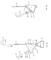
Figure 1A illustrates a load suspended from a vessel by a single lifting wire, andFigure 1B illustrates the load suspended by two lifting wires; -
Figure 2A shows in more detail a lifting block and connection elements, for a single fall crane lifting arrangement, according to the present invention which is illustrated inFigure 1A , andFigure 2B shows a three-dimensional detail; -
Figures 3A, 3B ,3C and 3D show successive stages in the process of a load being lifted off the deck of a vessel using a crane as a first lifting device and subsequent attachment of an A&R wire to the load; -
Figure 4A shows details of a wire load equalising arrangement for a single fall crane lifting arrangement andFigure 4B shows a three-dimensional detail; -
Figure 5A shows a lifting block and connection elements for a twin fall crane lifting arrangement; andFigure 5B shows a three-dimensional view thereof; -
Figure 6 shows operations in connection with hooking up a second lifting device, that is the A&R winch wire, to the lifting block of the twin fall arrangement type; -
Figures 7A and 7B show respectively details and a three-dimensional view of an arrangement with a twin fall first lifting device with wire load equalising, andFigure 7C shows a three dimensional view of an arrangement with a twin fall first lifting device and a twin fall second lifting device. -
Figure 8 shows schematically employment of a lifting block for a twin fall first lifting device and employing two cranes on a vessel, and -
Figure 9 shows various operations in the use of a lifting block, single fall first lifting arrangement, employing a strop and heave compensator optional arrangements. - Most construction and pipe lay vessels have two or more heavy lifting devices on board, for example one or more cranes and/or A&R facilities.
- By attaching two lifting devices to a load, the load in each lifting wire is halved. This means that half of the load weight becomes available as additional usable lifting wire weight, and the depth range of the combination can be extended beyond that of a single lifting device.
-
Figure 1A illustrates schematically avessel 1 having acrane 2 comprising a first lifting device, anA&R winch 3 comprising a second lifting device, alifting wire 4 from thecrane 2, and anA&R winch wire 5 from thewinch 3, which is illustrated as passing through amoon pool 6, but is not limited to such an arrangement. Also illustrated are alifting block 7 and aload 8 which may comprise a piece of equipment to be taken from the deck of the vessel and lowered to the sea bed, or in conjunction with A&R operations, a pipe to be lowered to or raised from the sea bed, or a vertical pipe riser system which may be installed/suspended vertically from a support structure. - By attaching two lifting devices to a load, the load in each lifting wire is halved.
Figure 1B illustrates the use of thelifting wire 4 and theA&R winch wire 5 to support theload 8. Using the two wires and two lifting devices means that half of the load weight becomes available as additional usable lifting wire weight, and the depth range of the combination can be extended beyond that of a single lifting device. - For example, when considering a
single fall crane 2, the total load in thecrane wire 4 for a given lift is the weight lifted plus the weight of the crane wire between the crane boom and the load. Such cranes are typical equipment aboard offshore construction vessels, and have a relatively high capacity as well as a substantial effective reach, for transferring objects around the deck of construction vessel, and placing and recovering objects from the sea floor and for loading items onto and unloading items from the vessel. - The rated capacity of a crane (whatever the.number of falls) is the allowable load applied to the crane boom by the sum of the loads in the lifting wires. In the case of the single fall arrangement, the load applied to the crane boom is therefore equal to the weight of the load lifted plus the weight of the single lifting wire between the boom and the load. These two weights added together should not therefore be allowed to exceed the rated capacity of the crane. From this it is possible to calculate the maximum depth that can be safely attained by a crane of known capacity and wire weight.
- For example: if the nominal rated capacity (WC) of the primary lift system such as a crane is 200 tonne, the lifting wire weight (Ww) is 40 kg/metre, and the load handled is 100 tonne (WL), then when the load reaches the maximum allowable at the crane boom, the depth D1max (metres) can be deduced from the fact that the wire weight (= 40 x D1max) and the load weight (= 100 x 1000) and that both added together must not exceed the crane rated capacity (= 200 x 1000). From this the maximum depth (D1max) = ((200-100) x 1000) ÷ 40 = 2500 m.
- If at this point the weight of the suspended load can be shared with another (secondary) lifting system (such as an A&R winch), then the effective weight of the suspended load acting on the crane boom is halved and D2max now = {[200-(100/2)] x 1000} ÷ 40 = 3750 m. This gives an increase of 1250 m operating depth. The weight of the additional wire being 40 x 1250 = 50000 kg = 50 tonne - i.e. the reduction in the load acting on the crane boom due to the additional lift provided by a second hoist.
- In very general terms therefore: the maximum working depth of a primary single fall lift system (Dmax) = (WC-WL) ÷ Ww. from which it can be seen that a reduction in WL - e.g. by sharing the load with an additional secondary lift system - gives an increase in the maximum allowable depth. This increase being equal to the resulting reduction in the load on the crane boom divided by the primary lift system wire weight per unit length.
- This arrangement can also be used with a multi-fall crane wire system, with an increase in depth commensurate with the number of falls.
- It should be noted that whilst this arrangement does increase the crane operating depth, it does not increase the weight that a given crane can handle. This is because the load will first have to be lifted overboard by this crane when operating on its own.
- The load sharing features can be utilized with fibre rope technology, which has the advantage of being significantly lighter in water than wire.
- An embodiment of lifting block according to the invention and comprising a single fall version will now be described with reference to
Figures 2 to 4 . - The
lifting block 7 enables the load sharing referred to above and has a built insheave 10. It is referred to in the following as a Dual Suspension Lifting Block (DSLB). - The block carries a
hook 25 of a hinged and swivelling type to ensure even load distribution. - The
sheave 10 is mounted between sheaveblock cheek plates 11, as can be seen fromFigures 2A and 2B between which are also provided suitably shaped wire guides 12 and asheave block shoulder 13 for a liftingwire end stop 14. - The lifting wire of the first lifting device, that is
crane wire 4, is fed into one side of theblock 7, passes around thesheave 10 and is terminated in the liftingwire end stop 14 which also provides one half (first connection element 19) of a connector, the other half (second connection element 15) of which is attached to the lifting wire of a second lifting device, namely theA&R winch wire 5. When the load is taken solely by thelifting wire 4 the liftingwire end stop 14 bears against theshoulder 13 of the sheave block and thecheek plates 11, as is particularly apparent inFigure 2B , and the arrangement is designed in order to take the full crane load. - When the block is suspended from the first lifting device (the crane) alone then, because the wire comes out from one side, the
block 7 hangs at an angle as illustrated inFigure 2A with theload 8 suspended beneath it. The wire guides 12 are controlled radius wire guides provided on thecheek plates 11 to maintain the lifting wire bend within correct limits, whilst also keeping it within the confines of the lifting block (DSLB). Asecond connection element 15 is fitted to the free end of the lifting wire of the secondary lifting device, for example the A&R wire, as indicated by dotted lines inFigures 2A and 2B . - The
first connection element 19 is particularly illustrated as a female connector and thesecond connection element 15 is particularly illustrated as a male connector element but reverse arrangements and other forms of connector can be used. - Since the connection has to be made in deep water the
connection elements Figure 3C . The ROV can be controlled for carrying out subsea operations in the vicinity of the vessel in response to control signals given from on board the lift vessel itself, or another support vessel. - Whilst the two lifting devices, or hoists, are described above as cranes and A&R facilities, the two lifting devices involved can be a combination of cranes and/or A&R facilities and/or other types of hoist, any of which can be operated over the ship's stern, side or through a moon pool.
- The lifting wires extending from the crane(s) and/or A&R winches can be widely separated on the vessel thereby minimising the possibility of the first and second lifting wires becoming entangled, for example by twisting around one another. This separation is possible because the crane boom can be used to move the load clear of the vessel's sides or stern, and the A&R wire can be fed down through a moon pool as illustrated in
Figure 1A orFigure 3B ,3C or 3D . - Once the second lifting wire, via the
second connection element 15, has been attached to thefirst connection element 19, by the ROV as indicated inFigure 3C , the deployed length of the first and second lifting wires is adjusted so that thewire end stop 14 is at an equilibrium position clear of the upper face of thelifting block 7, as shown inFigure 3D . This ensures that rotation of thesheave 10 is not constrained and thus that it can move as necessary to equalise the load in the two lifting wires, as illustrated inFigures 4A and 4B . In practice theseparation gap 24 between theend stop 14 and thelifting block 7 will be a safe distance which prevents contact and unwanted load transfer to a single lifting device, and be of the order of 25 to 50 metres, for example. - Both lifting devices can then be operated simultaneously, paying-out at the same rate to facilitate speedy deployment to the final depth, and conversely reeling-in during recovery.
- With the arrangement proposed, the heave compensation capability of the
crane 2 is retained, and can be used to attenuate the effect of ship movement on the load. It is important to note however that, because thecrane wire 4 passes around theDSLB sheave 10 and back to a fixed point on the vessel, via the second wire (A&R winch wire) 5, the crane lift mode has effectively changed from single to double fall (Figure 3D ). Hence any corrective movement supplied to thecrane wire 4 will need to be doubled to produce the required compensation. This may necessitate an increase in the spooling speed and/or the length of wire wound in or paid out by the heave compensation system, in order to achieve the necessary response. - In
Figure 9 there is shown a self-containedheave compensation system 17, that is a passive heave compensation device, which can be attached to a hook carried by thesecond lifting wire 5. This provides the second lifting wire with a heave compensation capability separate to that of the crane, which then only has to compensate for crane displacement. - The separation between the end of the
second lifting wire 5 and the load has to be such that the second lifting wire can be pulled across to approach the load and thefirst connection element 19 by theROV 16 to achieve a connection. This separation is therefore constrained by the thrust available from the ROV. To overcome/minimise this limitation: (a) The over-boarding position of thesecond lifting wire 5 can be moved closer to the crane. Once the connection is made it can be moved away as/before the load descends. (b) A neutrallybuoyant strop 18 can be attached to (pre-installed to) the end of the first or second lifting wire, which the ROV can then take from one to other with minimal thrust. (c) The end of thesecond lifting wire 5 can be fitted with buoyancy that counterbalances the weight of theend connection 15 and the wire, thus facilitating deployment across to the load by the ROV. - The construction of the lifting block, DSLB, 7 will be large and heavy, commensurate with the size of lifting wires involved, and this will facilitate lowering/raising of the block when unloaded, without hanging up on the wires or overturning etc.
- The sequence of events illustrated in
Figures 3A to 3D is as follows: - The
lifting block 7, with thefirst lift wire 4 in place fed around itssheave 10 and terminated in theend stop 14, is affixed to aload 8 on thevessel 1, and the load picked up by operation of thecrane 2,Figure 3A , and lowered overboard to a predetermined minimum depth at which it is possible to connect the second lifting wire 5 (Figure 3B ). The depth may be determined by the angle at which the second lifting wire must pass through themoon pool 6, where used, in order to avoid contact with its bottom edge. - The second lifting wire with the
second connection element 15 connected is lowered overboard until it is at the required attachment depth (Figure 3B ). TheROV 16 then takes the second connection element (male connector half) 15 across to theDSLB 7, and mates with the first connection element 19 (female connector half) (Figure 3C ). - The load is then taken up by the second lifting device 3 (
Figure 3D ) and shared between the two lifting devices, thewire stop 14 being set to be clear of thelifting block 7 in order to allow the load on the two lift wires to equalise. For this the lifting wire of the first lifting device is further paid out until there is a safe distance between the connection and the block, as described above, and subsequently the lifting devices are operated simultaneously, also as described above, that is in unison. - The advantages provided by the use of lifting
block 7, lifting wire end stop/first connection element second connection element 15 combination particularly arise from the fact that existing vessel equipment is used to extend the crane depth range. It particularly avoids the use of long pennant wires, winches, and hang off stops, and wire twist/entanglement is avoided by wide separation of the two lifting devices on the vessel. Operational times and costs are reduced as no extra wires, winches and wire handling is involved. - Whereas the above description is concerned with a single fall version, illustrated in
Figures 5A and 5B is a twinfall lifting block 20 comprising twolifting blocks 7 each having arespective sheave 10 and mounted in a spaced apart arrangement as is particularly apparent inFigure 5B . Afirst connection element 21 is mounted on anadditional block 22 having arespective sheave 23. In this case thefirst connection element 21 does not act as an end stop for the crane wire (first lifting wire 4), rather the first lifting wire passes around thesheave 10 of one of the pair of liftingblocks 7, around thesheave 23 of theadditional block 22 and round thesheave 10 of the other of the pair of liftingblocks 7 and back up to the crane where it is terminated and fixed to the crane boom. This is particularly apparent fromFigure 6 ,7A ,7B and8 . - The
additional block 22 bears against the sheave block shoulders 13 of both liftingblocks 7 when the load is suspended solely by thecrane lift wire 4. Hence theadditional block 22 acts as thestop 14 used in the single fall arrangement - As in the case of the single fall arrangement, an
ROV 16 is used to make the connection between the two connection elements, and subsequently the two lifting devices, which are both illustrated inFigure 8 ascranes 2, are operated to take up the load and equalise it with theadditional block 22 spaced apart from the lifting block 20 (Figures 7A, 7B ,8 ). The method of use of the twin fall arrangement is substantially the same as that described for the single fall arrangement, as are the advantages provided thereby. - As stated above: The rated capacity of a crane (whatever the number of falls) is the allowable load applied to the crane boom by the sum of the loads in the lifting wires. In the case of the twin fall arrangement, the load applied to the crane boom is therefore equal to the weight of the load lifted plus the weight of the twin lifting wires between the boom and the load. These two weights added together should not therefore be allowed to exceed the rated capacity of the crane. From this it is possible to calculate the maximum depth that can be safely attained by a twin fall crane of known capacity and wire weight.
- For example: If the nominal rated capacity of the twin fall crane (Wc) is 400 tonne, the lifting wire weight (Ww) is 40 kg/metre, and the load handled is 200 tonne (WL), then the load at the crane boom at depth D1max (metres) = the crane wire weight {= 2 x 40 x D1max) + the load weight (= 200 x 1000) = (400 x 1000) kg max. From this the maximum depth (D1max) = {(400-200) x 1000] ÷ 2 x 40 = 2500 m.
- If at this point the weight of the suspended load can be shared with another lifting system, then the effective weight of the suspended load acting on the crane boom is halved. And D2max now = [(400-(200/2)} x 1000] ÷ 2 x 40 = 3750 m.
- This gives an increase in operating depth of 1250m. The weight of the additional wire in the two legs being 2 x 40 x 1250 = 100000 kg = 100 tonne - i.e. (as for the single fall configuration described above), equal to the reduction in the load acting on the crane boom due to the additional lift provided by a second hoist.
- Again, in very general terms: the maximum working depth of a multi-fall lift system Dmax = {(WC - (WL)} ÷ N x Ww. where N = the number of cable falls. Again it can be seen that a reduction in WL - e.g. by sharing the load with an additional hoist - gives an increase in the maximum allowable depth. In this case the increase being equal to the resulting reduction in the load on the crane boom divided by the primary hoist wire weight per unit length times the number of falls.
- Whilst the above description covers the case of loads taken off the deck of the vessel, it is equally applicable to A&R types of operation. For an abandonment type of operation the first wire will be attached to a pipe at deck level and dropped to a predetermined level at which the second wire is added. For a recovery type of operation both the first and second wires will be attached to the pipe on the sea bed and used to lift the pipe until at the predetermined level when the second wire can be removed and the pipe lifted by the first lifting device alone.
- In the single fall arrangement the
first lifting wire 4 is terminated in the liftingwire end stop 14, which comprises one end of an element whose other end provides afirst connection element 19. Theend stop 14 rests/is supported on/bears against thesheave block shoulder 13 and effectively secures theend stop 14 to thelifting block 7 when the first lifting device is operated alone. - In the twin fall arrangement the
first lifting wire 4 is terminated back on (secured back at) the crane boom after having passed around the two sheaves of theblock 20 and the one sheave of theadditional block 22, thus effectively securing the additional block and the first connection element to theblock 20 when the first lifting device is operated alone. - In both cases, the first connection element is effectively supported on the lifting block by the lifting wire of the first lifting device, whereby a load attached to the lifting block can be raised or lowered by the first lifting device alone.
- Whereas
Figures 5A, 5B ,6 ,7A, 7B and8 are concerned with a combination of a twin fall first lifting device and a single fall second lifting device, another possibility is a combination of a twin fall first lifting device and a twin fall second lifting device with a lifting block arrangement as illustrated inFigure 7C . Theadditional block 22 is in this case connected to afurther block 30 around a sheave of which the lifting wire of the second lifting device is passed and is secured back at the second lifting device. There is aconnection 31 between theblocks further block 30 in this case. The twin fall second lifting device is particularly provided by an A&R winch in twin fall mode. - The primary aim of using the A&R winch in twin fall mode is to increase the overall lifting capacity available to the construction vessel by utilisation of the DSLB. This is because this configuration doubles the contribution to the lift which is available from an A&R winch of given load capacity. Because it makes no difference to the load experienced by the crane boom, the depth extension of the crane system remains the same as that obtained when a single fall A&R system contributes to the lift. Whereas, of course, a twin fall A&R winch halves the depth range available from a given maximum length of wire stored on the winch drum. This 2 x 2 fall DSLB is therefore more concerned with increasing the overall available lift capacity of a construction vessel, than with increasing the depth range of the vessel crane. Depending on the configuration used, the overall lift capacity when using DSLB becomes: Crane wire capacity x number of falls + A&R wire capacity x number of falls.
- The method of use is essentially the same as described for a single fall A&R winch.
- The load is lifted overboard by the crane, and lowered to a predetermined depth.
- The A&R winch is rigged as a twin fall unit, and its
block 30 also lowered to a predetermined depth. - By suitably manoeuvring the crane, and/or use of a fibre strop/pennant an ROV is able to connect the
A&R block 30 to the crane block 22 (not the DSLB 20). - By adjusting the crane and A&R wires, the
crane block 22 is moved a safe distance up from theDSLB 20, and the load is then lifted/lowered by operating the crane and A&R winch in unison. - As for other DSLB configurations, this 2 x 2 fall arrangement could also be attached to a load already on the sea bed for manoeuvring it to a new location as required.
- Whilst the invention has been particularly described with reference to cranes and A&R winches it is not to be considered as restricted thereto and may involve other lifting and load holding devices. The second lifting device could even be a static pennant that is connected to the lifting block at a predetermined depth, and instead of wires it is also applicable to use with synthetic fibre ropes.
Claims (18)
- A method for use in supporting a load, comprising the steps of:providing a lifting block (7) and associated first and second connection elements (19, 15);supporting the first connection element on the lifting block by means of a lifting wire or rope (4) of a first lifting device (2) whereby a load (8) attached to the lifting block (7) can be raised or lowered by the first lifting device alone;attaching the load (8) to the lifting block (7), whereby the first connection element (19) bears against the lifting block (7);operating the first lifting device (2) to cause the load (8) to reach a predetermined level;attaching the second connection element (15) to a lifting wire or rope (5) of a second lifting device (3) and operating the second lifting device (3) to cause the second connection element (15) to approach the first connection element (19);joining the first and second connection elements (19, 15) whereby the load (8) is supported by and shared between the first and second lifting devices (2, 3) with the first connection element (19) clear of the lifting block (7); andoperating the first and second lifting devices (2, 3) in unison to dispose the load (8) at a required position.
- The method according to claim 1 for supporting a said load from a floating vessel (1), wherein the first and second lifting devices (2, 3) are spaced apart on the vessel, the predetermined level is at a first depth under the vessel, and the required position is at a greater depth than the first depth.
- The method according to claim 2, including, following the joining step, the step of adjusting the lengths of the lifting wires or ropes (4, 5) of the first and second lifting devices (2, 3) to cause a predetermined displacement between the lifting block (7) and the first connection element (14).
- The method according to any one of the preceding claims wherein the first lifting device is a single fall device and the lifting block includes a sheave (10), and including the steps of feeding the lifting wire or rope (4) of the first lifting device (2) around the sheave and terminating the lifting wire or rope (4) of the first lifting device (2) to the first connection element (14) which, when the load is lifted by the first lifting device alone, forms an end stop which bears against the lifting block.
- The method according to claim 4, wherein the end stop (14) bears against cheek plates (11) of the sheave (10).
- The method according to any one of claims 1 to 3, wherein the first lifting device (2) is a twin fall device and the lifting block (20) has first and second sheaves (10) and the first connection element (21) has a respective sheave (23), wherein the lifting wire or rope (4) of the first lifting device (2) is fed around the first sheave (10) of the lifting block (20), around the respective sheave (23) of the first connection element (21), around the second sheave (10) of the lifting block (20) and secured back at the first lifting device (2), and wherein the load (8) is lifted by the first lifting device (9) alone the first connection element (21) bears against the lifting block.
- The method according to claim 6, wherein the first connection element (21) bears against cheek plates (11) of both the first and second sheaves (10) of the lifting block (7).
- The method according to claim 6 or claim 7, wherein the second lifting device is a twin fall device and comprises a further lifting block (30) around a sheave of which the lifting wire or rope (4) of the second lifting device is passed and is secured back at the second lifting device, and wherein the second connection element (22) is carried by the further lifting block (30).
- The method according to claim 2, including the step of disposing a heave compensator (17) in the lifting wire or rope (5) of the second lifting device.
- The method according to claim 2, wherein the first and second connector elements (19, 15) are joined by use of a remotely operated vehicle (16).
- The method according to claim 10, further including the step of disposing a neutrally buoyant strop (18), which is pre-installed on the lifting wire or rope (5) of the second lifting device (3), between the lifting wire or rope (5) of the second lifting device (3) and the first connector element (19) by the remotely operated vehicle (16) prior to said joining step whereby to facilitate operation of the remotely operated vehicle for said joining step.
- A lifting block system comprising a lifting block (7), a first connection element (19) and a second connection element (15),
wherein the lifting block (7) is configured to support a load (8) either from a first lifting device (2) alone or from the first lifting device (2) and a second lifting device (3) together,
wherein the first connection element is attachable to a lifting wire or rope (4) of the first lifting device (2), wherein the lifting block further comprises a sheave (10) such that when the lifting wire or rope (4) is fed around the sheave (10) an end stop of the first connection element (19) bears against the lifting block (7) when the load is supported by the first lifting device alone,
wherein the first connection element is connectable to the second connection element (15), and
wherein the second connecting element is attachable to a lifting wire or rope (5) of the second lifting device, such that when the first connection element (19) is connected to the second connection element (15) the load can be supported by the first and second lifting devices (2, 3) together such that the first connection element is movable clear of the lifting block (7) by movement of the lifting wire or rope (4) of the first lifting device (2) around the sheave (10). - The lifting block system according to claim 12, wherein for a single fall first lifting device the lifting block (7) includes a single sheave (10) and the first connection element is adapted to terminate the lifting wire or rope (4) of the first lifting device (2), which is fed around the sheave, and form an end stop (14) adapted to bear against the lifting block (7) when the load is supported by the first lifting device (2) alone.
- The lifting block system according to claim 13, wherein the lifting block (7) includes cheek plates (11) associated with the sheave and the end stop (14) is adapted to bear against the cheek plates when the load is supported by the first lifting device (2) alone.
- The lifting block system according to claim 12, wherein for a twin fall first lifting device the lifting block includes first and second sheaves (10) and the first connection element (21) has a respective sheave (23), wherein in use the lifting wire or rope (4) of the first lifting device (2) is fed around the first sheave (10) of the lifting block (7), around the respective sheave (23) of the first connection element (21), around the second sheave (10) of the lifting block (20) and secured back at the first lifting device (2), and wherein the first connection element (21) of the twin fall first lifting device is adapted to bear against the lifting block (7) when the load (8) is supported by the first lifting device (2) alone.
- The lifting block system according to claim 14 wherein the first connection element (21) of the twin fall first lifting device is adapted to bear against cheek plates (11) of both the first and second sheaves (10) of the lifting block (7).
- The lifting block system according to claim 15 or claim 16, wherein the second lifting device (3) is a twin fall device and comprises a further lifting block (30) around a sheave of which in use the lifting wire or rope (4) of the second lifting device is passed and secured back at the second lifting device, and wherein the second connection element (22) is carried by the further lifting block (30).
- The lifting block system according to any one of claims 12 to 17, and wherein the first connection element (19) comprises a female connector for engagement with a male connector comprising the second connector element (15) carried by the lifting wire or rope (5) of the second lifting device (3) or the further lifting block (30) respectively.
Applications Claiming Priority (2)
| Application Number | Priority Date | Filing Date | Title |
|---|---|---|---|
| GB0900763.4A GB2466983B (en) | 2009-01-16 | 2009-01-16 | A method and apparatus for supporting a load |
| PCT/EP2010/050388 WO2010081847A1 (en) | 2009-01-16 | 2010-01-14 | A method and apparatus for supporting a load |
Publications (2)
| Publication Number | Publication Date |
|---|---|
| EP2379404A1 EP2379404A1 (en) | 2011-10-26 |
| EP2379404B1 true EP2379404B1 (en) | 2014-05-21 |
Family
ID=40445948
Family Applications (1)
| Application Number | Title | Priority Date | Filing Date |
|---|---|---|---|
| EP10700548.0A Active EP2379404B1 (en) | 2009-01-16 | 2010-01-14 | A method and apparatus for supporting a load |
Country Status (6)
| Country | Link |
|---|---|
| US (1) | US8950997B2 (en) |
| EP (1) | EP2379404B1 (en) |
| AU (1) | AU2010205618B2 (en) |
| BR (1) | BRPI1006895A2 (en) |
| GB (1) | GB2466983B (en) |
| WO (1) | WO2010081847A1 (en) |
Cited By (1)
| Publication number | Priority date | Publication date | Assignee | Title |
|---|---|---|---|---|
| CN107487727A (en) * | 2017-07-14 | 2017-12-19 | 芜湖鼎瀚再制造技术有限公司 | A kind of metalwork melting Miniature hanging device |
Families Citing this family (20)
| Publication number | Priority date | Publication date | Assignee | Title |
|---|---|---|---|---|
| EP2189575B1 (en) * | 2008-11-19 | 2021-06-30 | DEME Offshore BE N.V. | Jack-up offshore platform and a method thereof |
| WO2011034422A2 (en) * | 2009-09-18 | 2011-03-24 | Itrec B.V. | Hoisting device |
| NO332453B1 (en) * | 2010-11-03 | 2012-09-17 | Nat Oilwell Varco Norway As | Ceiling tools to counteract the twisting of mainly dived ropes |
| GB2488767B (en) * | 2011-03-07 | 2013-06-05 | Technip France | Abandonment and recovery system |
| GB201104715D0 (en) | 2011-03-21 | 2011-05-04 | Saipem Spa | A/R Method and apparatus therefor |
| NO20120936A1 (en) * | 2012-08-22 | 2014-02-24 | Rolls Royce Marine As | Procedure for lowering and raising cargo to or from the seabed |
| GB201218569D0 (en) * | 2012-10-16 | 2012-11-28 | Mojo Maritime Ltd | Improvements in or relating to marine operations |
| US9688516B2 (en) | 2013-03-15 | 2017-06-27 | Oil States Industries, Inc. | Elastomeric load compensators for load compensation of cranes |
| US9732820B2 (en) | 2014-03-13 | 2017-08-15 | Oil States Industries, Inc. | Load compensator having tension spring assemblies contained in a tubular housing |
| NL2017736B1 (en) * | 2016-11-07 | 2018-05-23 | Heerema Marine Contractors Nl | A method of handing over a load, and an arrangement to hand over a load. |
| NL2017978B1 (en) * | 2016-12-12 | 2018-06-26 | Heerema Marine Contractors Nl | Deep water hoisting device, and a method to lower a load to a deep sea level. |
| US10267124B2 (en) | 2016-12-13 | 2019-04-23 | Chevron U.S.A. Inc. | Subsea live hydrocarbon fluid retrieval system and method |
| CN110382346B (en) * | 2017-01-16 | 2021-10-01 | 伊特里克公司 | Deep water hoisting system and method |
| NL2020389B1 (en) * | 2018-02-06 | 2019-08-14 | Itrec Bv | A crane |
| CN108821147A (en) * | 2018-05-17 | 2018-11-16 | 广州益为科技有限公司 | One kind is to organic waste pre-processing device |
| CN108584738A (en) * | 2018-05-17 | 2018-09-28 | 永春辛德环保科技有限公司 | A kind of organic waste pre-processing device |
| CN108862067A (en) * | 2018-05-17 | 2018-11-23 | 广州益为科技有限公司 | One kind being used for organic waste pre-processing device |
| GB2576333B (en) | 2018-08-14 | 2021-06-02 | Subsea 7 Do Brasil Servicos Ltda | Handling loads in subsea operations |
| NL2022877B1 (en) * | 2019-04-05 | 2020-10-12 | Itrec Bv | heave compensated dual hoist crane |
| CN111661772B (en) * | 2020-04-28 | 2022-10-04 | 武汉船用机械有限责任公司 | Diving equipment drags hoisting accessory |
Family Cites Families (20)
| Publication number | Priority date | Publication date | Assignee | Title |
|---|---|---|---|---|
| US2358249A (en) | 1943-03-25 | 1944-09-12 | Bethlehem Steel Corp | Wrench |
| US3258249A (en) * | 1965-08-10 | 1966-06-28 | Newport News S & D Co | Multi-speed pulling apparatus |
| DE1817766A1 (en) | 1967-11-22 | 1971-02-11 | Uniroyal Inc | Method of making an electrical underwater towing and connecting cable |
| US3687418A (en) * | 1970-08-13 | 1972-08-29 | Rapp Fabrikher As | Method and apparatus for hauling underwater ropes and the like |
| FR2242290B1 (en) * | 1973-09-03 | 1977-02-25 | Subsea Equipment Ass Ltd | |
| DD202676A1 (en) * | 1981-07-09 | 1983-09-28 | Toppe Hans Ernst | SEAGING SUBSYSTEM FOR SHIP CRANES |
| JP2792662B2 (en) | 1989-02-20 | 1998-09-03 | 三菱重工業株式会社 | Cable ship |
| NO921796D0 (en) | 1992-05-06 | 1992-05-06 | Karmoey Winch As | USE OF A PASSIVE COMPENSATION DEVICE |
| JP2001200955A (en) * | 2000-01-19 | 2001-07-27 | Sumitomo Metal Ind Ltd | Laying method and morring method of undersea floating pipeline |
| GB0014188D0 (en) * | 2000-06-12 | 2000-08-02 | Engineering Business Ltd | Improvements to cable ships |
| WO2003062042A1 (en) * | 2002-01-24 | 2003-07-31 | Stolt Offshore Limited | Method and apparatus for deploying articles in deep waters |
| FR2852917B1 (en) * | 2003-03-26 | 2005-06-24 | Saipem Sa | SEALED COMPARTMENT RECEPTACLE AND METHOD OF PLACING IT TO RECOVER POLLUTANT EFFLUENTS FROM A EPAVE |
| GB2434627B (en) * | 2006-01-31 | 2010-10-20 | Subsea 7 Ltd | Apparatus and method for laying down, abandoning and recovering a pipe on the sea floor |
| CN101466591B (en) * | 2006-06-16 | 2013-03-20 | Itrec有限责任公司 | Heaving movement compensation |
| US8381578B2 (en) | 2007-02-12 | 2013-02-26 | Valkyrie Commissioning Services Inc. | Subsea pipeline service skid |
| DE602007014414D1 (en) * | 2007-06-22 | 2011-06-16 | Itrec Bv | SHIP LOADING AND LIFTING SYSTEM |
| NO330923B1 (en) * | 2007-07-05 | 2011-08-15 | Nat Oilwell Norway As | Procedure for hoisting a package at sea |
| BRPI0800140A2 (en) * | 2008-02-01 | 2009-10-20 | Zytech Industrial Ltda | process for lowering equipment to the bottom of the sea |
| BRPI0901003A2 (en) * | 2008-04-22 | 2010-04-06 | Aker Marine Contractors As | method of extending a seabed object in very deep water from a boat with a compensated rocking crane, and apparatus for supporting the loading of a submerged object suspended from a boat |
| DE102008059805A1 (en) * | 2008-12-01 | 2010-06-02 | Liebherr-Werk Nenzing Gmbh | Device for lifting and lowering of load in water, has lifting unit with hoist rope and storage drum with another hoist rope, which are particularly arranged on floating unit |
-
2009
- 2009-01-16 GB GB0900763.4A patent/GB2466983B/en active Active
-
2010
- 2010-01-14 AU AU2010205618A patent/AU2010205618B2/en not_active Ceased
- 2010-01-14 EP EP10700548.0A patent/EP2379404B1/en active Active
- 2010-01-14 US US13/138,169 patent/US8950997B2/en not_active Expired - Fee Related
- 2010-01-14 BR BRPI1006895A patent/BRPI1006895A2/en active Search and Examination
- 2010-01-14 WO PCT/EP2010/050388 patent/WO2010081847A1/en active Application Filing
Cited By (1)
| Publication number | Priority date | Publication date | Assignee | Title |
|---|---|---|---|---|
| CN107487727A (en) * | 2017-07-14 | 2017-12-19 | 芜湖鼎瀚再制造技术有限公司 | A kind of metalwork melting Miniature hanging device |
Also Published As
| Publication number | Publication date |
|---|---|
| AU2010205618B2 (en) | 2014-10-09 |
| AU2010205618A1 (en) | 2011-08-04 |
| US20120156003A1 (en) | 2012-06-21 |
| GB2466983A (en) | 2010-07-21 |
| GB0900763D0 (en) | 2009-03-04 |
| BRPI1006895A2 (en) | 2016-02-10 |
| EP2379404A1 (en) | 2011-10-26 |
| GB2466983B (en) | 2013-10-30 |
| US8950997B2 (en) | 2015-02-10 |
| WO2010081847A1 (en) | 2010-07-22 |
Similar Documents
| Publication | Publication Date | Title |
|---|---|---|
| EP2379404B1 (en) | A method and apparatus for supporting a load | |
| US8882427B2 (en) | Method and device for hoisting an item by means of a crane | |
| JP7025433B2 (en) | Deep sea hoisting system and method | |
| EP3018087B1 (en) | Hoisting device | |
| US7543799B2 (en) | Method and apparatus for deploying articles in deep waters | |
| EP2847417B1 (en) | Offshore vessel and method of operation of such an offshore vessel | |
| EP2424775B1 (en) | Spar mooring line sharing method and system | |
| RU2182883C2 (en) | Deep-water load-lowering device | |
| NO330923B1 (en) | Procedure for hoisting a package at sea | |
| US20150217838A1 (en) | Method for lowering and hoisting of a load to or from an ocean floor | |
| WO2014083056A1 (en) | An underwater connecting system | |
| US20220227467A1 (en) | Deployment of Unmanned Underwater Vehicles | |
| EP2467632B1 (en) | An offshore s-lay pipelaying vessel | |
| US8016521B1 (en) | Method for deploying a deepwater mooring spread | |
| CN114198569B (en) | Underwater connection method of dynamic flexible pipe cable and anchoring base | |
| KR100978065B1 (en) | Method for mounting thruster in drillship | |
| WO2013073950A1 (en) | Vessel and method for towing a heavy load under water | |
| WO2017095229A9 (en) | Method for replacing flexible products whilst installation vessel is positioned away from platform | |
| US20230192457A1 (en) | Multi-winch hoisting system and method for combining multiple-winches in a hoisting system | |
| CN115339572A (en) | Protective laying method for deepwater mooring cable |
Legal Events
| Date | Code | Title | Description |
|---|---|---|---|
| PUAI | Public reference made under article 153(3) epc to a published international application that has entered the european phase |
Free format text: ORIGINAL CODE: 0009012 |
|
| 17P | Request for examination filed |
Effective date: 20110720 |
|
| AK | Designated contracting states |
Kind code of ref document: A1 Designated state(s): AT BE BG CH CY CZ DE DK EE ES FI FR GB GR HR HU IE IS IT LI LT LU LV MC MK MT NL NO PL PT RO SE SI SK SM TR |
|
| DAX | Request for extension of the european patent (deleted) | ||
| 17Q | First examination report despatched |
Effective date: 20130109 |
|
| RAP1 | Party data changed (applicant data changed or rights of an application transferred) |
Owner name: SUBSEA 7 LIMITED |
|
| GRAP | Despatch of communication of intention to grant a patent |
Free format text: ORIGINAL CODE: EPIDOSNIGR1 |
|
| INTG | Intention to grant announced |
Effective date: 20140224 |
|
| GRAS | Grant fee paid |
Free format text: ORIGINAL CODE: EPIDOSNIGR3 |
|
| GRAA | (expected) grant |
Free format text: ORIGINAL CODE: 0009210 |
|
| AK | Designated contracting states |
Kind code of ref document: B1 Designated state(s): AT BE BG CH CY CZ DE DK EE ES FI FR GB GR HR HU IE IS IT LI LT LU LV MC MK MT NL NO PL PT RO SE SI SK SM TR |
|
| REG | Reference to a national code |
Ref country code: GB Ref legal event code: FG4D |
|
| REG | Reference to a national code |
Ref country code: CH Ref legal event code: EP |
|
| REG | Reference to a national code |
Ref country code: AT Ref legal event code: REF Ref document number: 669450 Country of ref document: AT Kind code of ref document: T Effective date: 20140615 |
|
| REG | Reference to a national code |
Ref country code: IE Ref legal event code: FG4D |
|
| REG | Reference to a national code |
Ref country code: DE Ref legal event code: R096 Ref document number: 602010016227 Country of ref document: DE Effective date: 20140710 |
|
| REG | Reference to a national code |
Ref country code: NL Ref legal event code: T3 |
|
| REG | Reference to a national code |
Ref country code: NO Ref legal event code: T2 Effective date: 20140521 |
|
| REG | Reference to a national code |
Ref country code: AT Ref legal event code: MK05 Ref document number: 669450 Country of ref document: AT Kind code of ref document: T Effective date: 20140521 |
|
| REG | Reference to a national code |
Ref country code: LT Ref legal event code: MG4D |
|
| PG25 | Lapsed in a contracting state [announced via postgrant information from national office to epo] |
Ref country code: LT Free format text: LAPSE BECAUSE OF FAILURE TO SUBMIT A TRANSLATION OF THE DESCRIPTION OR TO PAY THE FEE WITHIN THE PRESCRIBED TIME-LIMIT Effective date: 20140521 Ref country code: IS Free format text: LAPSE BECAUSE OF FAILURE TO SUBMIT A TRANSLATION OF THE DESCRIPTION OR TO PAY THE FEE WITHIN THE PRESCRIBED TIME-LIMIT Effective date: 20140921 Ref country code: FI Free format text: LAPSE BECAUSE OF FAILURE TO SUBMIT A TRANSLATION OF THE DESCRIPTION OR TO PAY THE FEE WITHIN THE PRESCRIBED TIME-LIMIT Effective date: 20140521 Ref country code: GR Free format text: LAPSE BECAUSE OF FAILURE TO SUBMIT A TRANSLATION OF THE DESCRIPTION OR TO PAY THE FEE WITHIN THE PRESCRIBED TIME-LIMIT Effective date: 20140822 |
|
| PG25 | Lapsed in a contracting state [announced via postgrant information from national office to epo] |
Ref country code: PL Free format text: LAPSE BECAUSE OF FAILURE TO SUBMIT A TRANSLATION OF THE DESCRIPTION OR TO PAY THE FEE WITHIN THE PRESCRIBED TIME-LIMIT Effective date: 20140521 Ref country code: ES Free format text: LAPSE BECAUSE OF FAILURE TO SUBMIT A TRANSLATION OF THE DESCRIPTION OR TO PAY THE FEE WITHIN THE PRESCRIBED TIME-LIMIT Effective date: 20140521 Ref country code: LV Free format text: LAPSE BECAUSE OF FAILURE TO SUBMIT A TRANSLATION OF THE DESCRIPTION OR TO PAY THE FEE WITHIN THE PRESCRIBED TIME-LIMIT Effective date: 20140521 Ref country code: HR Free format text: LAPSE BECAUSE OF FAILURE TO SUBMIT A TRANSLATION OF THE DESCRIPTION OR TO PAY THE FEE WITHIN THE PRESCRIBED TIME-LIMIT Effective date: 20140521 Ref country code: AT Free format text: LAPSE BECAUSE OF FAILURE TO SUBMIT A TRANSLATION OF THE DESCRIPTION OR TO PAY THE FEE WITHIN THE PRESCRIBED TIME-LIMIT Effective date: 20140521 Ref country code: SE Free format text: LAPSE BECAUSE OF FAILURE TO SUBMIT A TRANSLATION OF THE DESCRIPTION OR TO PAY THE FEE WITHIN THE PRESCRIBED TIME-LIMIT Effective date: 20140521 |
|
| PG25 | Lapsed in a contracting state [announced via postgrant information from national office to epo] |
Ref country code: PT Free format text: LAPSE BECAUSE OF FAILURE TO SUBMIT A TRANSLATION OF THE DESCRIPTION OR TO PAY THE FEE WITHIN THE PRESCRIBED TIME-LIMIT Effective date: 20140922 |
|
| PG25 | Lapsed in a contracting state [announced via postgrant information from national office to epo] |
Ref country code: EE Free format text: LAPSE BECAUSE OF FAILURE TO SUBMIT A TRANSLATION OF THE DESCRIPTION OR TO PAY THE FEE WITHIN THE PRESCRIBED TIME-LIMIT Effective date: 20140521 Ref country code: DK Free format text: LAPSE BECAUSE OF FAILURE TO SUBMIT A TRANSLATION OF THE DESCRIPTION OR TO PAY THE FEE WITHIN THE PRESCRIBED TIME-LIMIT Effective date: 20140521 Ref country code: BE Free format text: LAPSE BECAUSE OF FAILURE TO SUBMIT A TRANSLATION OF THE DESCRIPTION OR TO PAY THE FEE WITHIN THE PRESCRIBED TIME-LIMIT Effective date: 20140521 Ref country code: SK Free format text: LAPSE BECAUSE OF FAILURE TO SUBMIT A TRANSLATION OF THE DESCRIPTION OR TO PAY THE FEE WITHIN THE PRESCRIBED TIME-LIMIT Effective date: 20140521 Ref country code: CZ Free format text: LAPSE BECAUSE OF FAILURE TO SUBMIT A TRANSLATION OF THE DESCRIPTION OR TO PAY THE FEE WITHIN THE PRESCRIBED TIME-LIMIT Effective date: 20140521 Ref country code: RO Free format text: LAPSE BECAUSE OF FAILURE TO SUBMIT A TRANSLATION OF THE DESCRIPTION OR TO PAY THE FEE WITHIN THE PRESCRIBED TIME-LIMIT Effective date: 20140521 |
|
| REG | Reference to a national code |
Ref country code: DE Ref legal event code: R097 Ref document number: 602010016227 Country of ref document: DE |
|
| PLBE | No opposition filed within time limit |
Free format text: ORIGINAL CODE: 0009261 |
|
| STAA | Information on the status of an ep patent application or granted ep patent |
Free format text: STATUS: NO OPPOSITION FILED WITHIN TIME LIMIT |
|
| 26N | No opposition filed |
Effective date: 20150224 |
|
| REG | Reference to a national code |
Ref country code: DE Ref legal event code: R097 Ref document number: 602010016227 Country of ref document: DE Effective date: 20150224 |
|
| PG25 | Lapsed in a contracting state [announced via postgrant information from national office to epo] |
Ref country code: SI Free format text: LAPSE BECAUSE OF FAILURE TO SUBMIT A TRANSLATION OF THE DESCRIPTION OR TO PAY THE FEE WITHIN THE PRESCRIBED TIME-LIMIT Effective date: 20140521 |
|
| REG | Reference to a national code |
Ref country code: DE Ref legal event code: R119 Ref document number: 602010016227 Country of ref document: DE |
|
| REG | Reference to a national code |
Ref country code: CH Ref legal event code: PL |
|
| PG25 | Lapsed in a contracting state [announced via postgrant information from national office to epo] |
Ref country code: LU Free format text: LAPSE BECAUSE OF FAILURE TO SUBMIT A TRANSLATION OF THE DESCRIPTION OR TO PAY THE FEE WITHIN THE PRESCRIBED TIME-LIMIT Effective date: 20150114 |
|
| PG25 | Lapsed in a contracting state [announced via postgrant information from national office to epo] |
Ref country code: MC Free format text: LAPSE BECAUSE OF FAILURE TO SUBMIT A TRANSLATION OF THE DESCRIPTION OR TO PAY THE FEE WITHIN THE PRESCRIBED TIME-LIMIT Effective date: 20140521 |
|
| PG25 | Lapsed in a contracting state [announced via postgrant information from national office to epo] |
Ref country code: DE Free format text: LAPSE BECAUSE OF NON-PAYMENT OF DUE FEES Effective date: 20150801 Ref country code: LI Free format text: LAPSE BECAUSE OF NON-PAYMENT OF DUE FEES Effective date: 20150131 Ref country code: CH Free format text: LAPSE BECAUSE OF NON-PAYMENT OF DUE FEES Effective date: 20150131 |
|
| REG | Reference to a national code |
Ref country code: IE Ref legal event code: MM4A |
|
| REG | Reference to a national code |
Ref country code: FR Ref legal event code: PLFP Year of fee payment: 7 |
|
| PG25 | Lapsed in a contracting state [announced via postgrant information from national office to epo] |
Ref country code: IE Free format text: LAPSE BECAUSE OF NON-PAYMENT OF DUE FEES Effective date: 20150114 |
|
| PG25 | Lapsed in a contracting state [announced via postgrant information from national office to epo] |
Ref country code: MT Free format text: LAPSE BECAUSE OF FAILURE TO SUBMIT A TRANSLATION OF THE DESCRIPTION OR TO PAY THE FEE WITHIN THE PRESCRIBED TIME-LIMIT Effective date: 20140521 |
|
| REG | Reference to a national code |
Ref country code: FR Ref legal event code: PLFP Year of fee payment: 8 |
|
| REG | Reference to a national code |
Ref country code: NO Ref legal event code: CHAD Owner name: SUBSEA 7 LIMITED, GB |
|
| PG25 | Lapsed in a contracting state [announced via postgrant information from national office to epo] |
Ref country code: SM Free format text: LAPSE BECAUSE OF FAILURE TO SUBMIT A TRANSLATION OF THE DESCRIPTION OR TO PAY THE FEE WITHIN THE PRESCRIBED TIME-LIMIT Effective date: 20140521 Ref country code: HU Free format text: LAPSE BECAUSE OF FAILURE TO SUBMIT A TRANSLATION OF THE DESCRIPTION OR TO PAY THE FEE WITHIN THE PRESCRIBED TIME-LIMIT; INVALID AB INITIO Effective date: 20100114 Ref country code: BG Free format text: LAPSE BECAUSE OF FAILURE TO SUBMIT A TRANSLATION OF THE DESCRIPTION OR TO PAY THE FEE WITHIN THE PRESCRIBED TIME-LIMIT Effective date: 20140521 |
|
| PG25 | Lapsed in a contracting state [announced via postgrant information from national office to epo] |
Ref country code: CY Free format text: LAPSE BECAUSE OF FAILURE TO SUBMIT A TRANSLATION OF THE DESCRIPTION OR TO PAY THE FEE WITHIN THE PRESCRIBED TIME-LIMIT Effective date: 20140521 |
|
| PG25 | Lapsed in a contracting state [announced via postgrant information from national office to epo] |
Ref country code: TR Free format text: LAPSE BECAUSE OF FAILURE TO SUBMIT A TRANSLATION OF THE DESCRIPTION OR TO PAY THE FEE WITHIN THE PRESCRIBED TIME-LIMIT Effective date: 20140521 |
|
| REG | Reference to a national code |
Ref country code: FR Ref legal event code: PLFP Year of fee payment: 9 |
|
| REG | Reference to a national code |
Ref country code: FR Ref legal event code: CA Effective date: 20180221 |
|
| PG25 | Lapsed in a contracting state [announced via postgrant information from national office to epo] |
Ref country code: MK Free format text: LAPSE BECAUSE OF FAILURE TO SUBMIT A TRANSLATION OF THE DESCRIPTION OR TO PAY THE FEE WITHIN THE PRESCRIBED TIME-LIMIT Effective date: 20140521 |
|
| PGFP | Annual fee paid to national office [announced via postgrant information from national office to epo] |
Ref country code: PL Payment date: 20190124 Year of fee payment: 11 Ref country code: FR Payment date: 20190122 Year of fee payment: 10 |
|
| PG25 | Lapsed in a contracting state [announced via postgrant information from national office to epo] |
Ref country code: FR Free format text: LAPSE BECAUSE OF NON-PAYMENT OF DUE FEES Effective date: 20200131 |
|
| PG25 | Lapsed in a contracting state [announced via postgrant information from national office to epo] |
Ref country code: IT Free format text: LAPSE BECAUSE OF NON-PAYMENT OF DUE FEES Effective date: 20200114 |
|
| PGFP | Annual fee paid to national office [announced via postgrant information from national office to epo] |
Ref country code: NO Payment date: 20230120 Year of fee payment: 14 |
|
| PGFP | Annual fee paid to national office [announced via postgrant information from national office to epo] |
Ref country code: GB Payment date: 20230130 Year of fee payment: 14 |
|
| PGFP | Annual fee paid to national office [announced via postgrant information from national office to epo] |
Ref country code: NL Payment date: 20230124 Year of fee payment: 14 |
|
| PGFP | Annual fee paid to national office [announced via postgrant information from national office to epo] |
Ref country code: NL Payment date: 20240123 Year of fee payment: 15 |