EP2378985B1 - Orientierungsführung - Google Patents
Orientierungsführung Download PDFInfo
- Publication number
- EP2378985B1 EP2378985B1 EP09801536.5A EP09801536A EP2378985B1 EP 2378985 B1 EP2378985 B1 EP 2378985B1 EP 09801536 A EP09801536 A EP 09801536A EP 2378985 B1 EP2378985 B1 EP 2378985B1
- Authority
- EP
- European Patent Office
- Prior art keywords
- housing
- indicator
- relative
- axis
- instrument
- Prior art date
- Legal status (The legal status is an assumption and is not a legal conclusion. Google has not performed a legal analysis and makes no representation as to the accuracy of the status listed.)
- Not-in-force
Links
- 230000008878 coupling Effects 0.000 description 10
- 238000010168 coupling process Methods 0.000 description 10
- 238000005859 coupling reaction Methods 0.000 description 10
- 238000002513 implantation Methods 0.000 description 10
- 239000012530 fluid Substances 0.000 description 9
- 238000000034 method Methods 0.000 description 8
- 238000005096 rolling process Methods 0.000 description 6
- 238000001356 surgical procedure Methods 0.000 description 4
- 230000007935 neutral effect Effects 0.000 description 3
- 210000000588 acetabulum Anatomy 0.000 description 2
- 244000309464 bull Species 0.000 description 2
- FAPWRFPIFSIZLT-UHFFFAOYSA-M Sodium chloride Chemical compound [Na+].[Cl-] FAPWRFPIFSIZLT-UHFFFAOYSA-M 0.000 description 1
- 210000000629 knee joint Anatomy 0.000 description 1
- 239000007788 liquid Substances 0.000 description 1
- 238000005259 measurement Methods 0.000 description 1
- 238000012986 modification Methods 0.000 description 1
- 230000004048 modification Effects 0.000 description 1
- 210000004197 pelvis Anatomy 0.000 description 1
- 230000035945 sensitivity Effects 0.000 description 1
- 239000007787 solid Substances 0.000 description 1
- 210000003813 thumb Anatomy 0.000 description 1
- 230000000007 visual effect Effects 0.000 description 1
Images

Classifications
-
- A—HUMAN NECESSITIES
- A61—MEDICAL OR VETERINARY SCIENCE; HYGIENE
- A61F—FILTERS IMPLANTABLE INTO BLOOD VESSELS; PROSTHESES; DEVICES PROVIDING PATENCY TO, OR PREVENTING COLLAPSING OF, TUBULAR STRUCTURES OF THE BODY, e.g. STENTS; ORTHOPAEDIC, NURSING OR CONTRACEPTIVE DEVICES; FOMENTATION; TREATMENT OR PROTECTION OF EYES OR EARS; BANDAGES, DRESSINGS OR ABSORBENT PADS; FIRST-AID KITS
- A61F2/00—Filters implantable into blood vessels; Prostheses, i.e. artificial substitutes or replacements for parts of the body; Appliances for connecting them with the body; Devices providing patency to, or preventing collapsing of, tubular structures of the body, e.g. stents
- A61F2/02—Prostheses implantable into the body
- A61F2/30—Joints
- A61F2/46—Special tools for implanting artificial joints
- A61F2/4657—Measuring instruments used for implanting artificial joints
-
- A—HUMAN NECESSITIES
- A61—MEDICAL OR VETERINARY SCIENCE; HYGIENE
- A61B—DIAGNOSIS; SURGERY; IDENTIFICATION
- A61B17/00—Surgical instruments, devices or methods
- A61B17/16—Instruments for performing osteoclasis; Drills or chisels for bones; Trepans
- A61B17/17—Guides or aligning means for drills, mills, pins or wires
- A61B17/1739—Guides or aligning means for drills, mills, pins or wires specially adapted for particular parts of the body
- A61B17/1742—Guides or aligning means for drills, mills, pins or wires specially adapted for particular parts of the body for the hip
- A61B17/1746—Guides or aligning means for drills, mills, pins or wires specially adapted for particular parts of the body for the hip for the acetabulum
-
- A—HUMAN NECESSITIES
- A61—MEDICAL OR VETERINARY SCIENCE; HYGIENE
- A61F—FILTERS IMPLANTABLE INTO BLOOD VESSELS; PROSTHESES; DEVICES PROVIDING PATENCY TO, OR PREVENTING COLLAPSING OF, TUBULAR STRUCTURES OF THE BODY, e.g. STENTS; ORTHOPAEDIC, NURSING OR CONTRACEPTIVE DEVICES; FOMENTATION; TREATMENT OR PROTECTION OF EYES OR EARS; BANDAGES, DRESSINGS OR ABSORBENT PADS; FIRST-AID KITS
- A61F2/00—Filters implantable into blood vessels; Prostheses, i.e. artificial substitutes or replacements for parts of the body; Appliances for connecting them with the body; Devices providing patency to, or preventing collapsing of, tubular structures of the body, e.g. stents
- A61F2/02—Prostheses implantable into the body
- A61F2/30—Joints
- A61F2/46—Special tools for implanting artificial joints
- A61F2/4603—Special tools for implanting artificial joints for insertion or extraction of endoprosthetic joints or of accessories thereof
-
- A—HUMAN NECESSITIES
- A61—MEDICAL OR VETERINARY SCIENCE; HYGIENE
- A61B—DIAGNOSIS; SURGERY; IDENTIFICATION
- A61B90/00—Instruments, implements or accessories specially adapted for surgery or diagnosis and not covered by any of the groups A61B1/00 - A61B50/00, e.g. for luxation treatment or for protecting wound edges
- A61B90/06—Measuring instruments not otherwise provided for
-
- A—HUMAN NECESSITIES
- A61—MEDICAL OR VETERINARY SCIENCE; HYGIENE
- A61F—FILTERS IMPLANTABLE INTO BLOOD VESSELS; PROSTHESES; DEVICES PROVIDING PATENCY TO, OR PREVENTING COLLAPSING OF, TUBULAR STRUCTURES OF THE BODY, e.g. STENTS; ORTHOPAEDIC, NURSING OR CONTRACEPTIVE DEVICES; FOMENTATION; TREATMENT OR PROTECTION OF EYES OR EARS; BANDAGES, DRESSINGS OR ABSORBENT PADS; FIRST-AID KITS
- A61F2/00—Filters implantable into blood vessels; Prostheses, i.e. artificial substitutes or replacements for parts of the body; Appliances for connecting them with the body; Devices providing patency to, or preventing collapsing of, tubular structures of the body, e.g. stents
- A61F2/02—Prostheses implantable into the body
- A61F2/30—Joints
- A61F2/32—Joints for the hip
- A61F2/34—Acetabular cups
-
- A—HUMAN NECESSITIES
- A61—MEDICAL OR VETERINARY SCIENCE; HYGIENE
- A61F—FILTERS IMPLANTABLE INTO BLOOD VESSELS; PROSTHESES; DEVICES PROVIDING PATENCY TO, OR PREVENTING COLLAPSING OF, TUBULAR STRUCTURES OF THE BODY, e.g. STENTS; ORTHOPAEDIC, NURSING OR CONTRACEPTIVE DEVICES; FOMENTATION; TREATMENT OR PROTECTION OF EYES OR EARS; BANDAGES, DRESSINGS OR ABSORBENT PADS; FIRST-AID KITS
- A61F2/00—Filters implantable into blood vessels; Prostheses, i.e. artificial substitutes or replacements for parts of the body; Appliances for connecting them with the body; Devices providing patency to, or preventing collapsing of, tubular structures of the body, e.g. stents
- A61F2/02—Prostheses implantable into the body
- A61F2/30—Joints
- A61F2002/30001—Additional features of subject-matter classified in A61F2/28, A61F2/30 and subgroups thereof
- A61F2002/30316—The prosthesis having different structural features at different locations within the same prosthesis; Connections between prosthetic parts; Special structural features of bone or joint prostheses not otherwise provided for
- A61F2002/30329—Connections or couplings between prosthetic parts, e.g. between modular parts; Connecting elements
- A61F2002/30471—Connections or couplings between prosthetic parts, e.g. between modular parts; Connecting elements connected by a hinged linkage mechanism, e.g. of the single-bar or multi-bar linkage type
-
- A—HUMAN NECESSITIES
- A61—MEDICAL OR VETERINARY SCIENCE; HYGIENE
- A61F—FILTERS IMPLANTABLE INTO BLOOD VESSELS; PROSTHESES; DEVICES PROVIDING PATENCY TO, OR PREVENTING COLLAPSING OF, TUBULAR STRUCTURES OF THE BODY, e.g. STENTS; ORTHOPAEDIC, NURSING OR CONTRACEPTIVE DEVICES; FOMENTATION; TREATMENT OR PROTECTION OF EYES OR EARS; BANDAGES, DRESSINGS OR ABSORBENT PADS; FIRST-AID KITS
- A61F2/00—Filters implantable into blood vessels; Prostheses, i.e. artificial substitutes or replacements for parts of the body; Appliances for connecting them with the body; Devices providing patency to, or preventing collapsing of, tubular structures of the body, e.g. stents
- A61F2/02—Prostheses implantable into the body
- A61F2/30—Joints
- A61F2002/30001—Additional features of subject-matter classified in A61F2/28, A61F2/30 and subgroups thereof
- A61F2002/30316—The prosthesis having different structural features at different locations within the same prosthesis; Connections between prosthetic parts; Special structural features of bone or joint prostheses not otherwise provided for
- A61F2002/30535—Special structural features of bone or joint prostheses not otherwise provided for
- A61F2002/30617—Visible markings for adjusting, locating or measuring
-
- A—HUMAN NECESSITIES
- A61—MEDICAL OR VETERINARY SCIENCE; HYGIENE
- A61F—FILTERS IMPLANTABLE INTO BLOOD VESSELS; PROSTHESES; DEVICES PROVIDING PATENCY TO, OR PREVENTING COLLAPSING OF, TUBULAR STRUCTURES OF THE BODY, e.g. STENTS; ORTHOPAEDIC, NURSING OR CONTRACEPTIVE DEVICES; FOMENTATION; TREATMENT OR PROTECTION OF EYES OR EARS; BANDAGES, DRESSINGS OR ABSORBENT PADS; FIRST-AID KITS
- A61F2/00—Filters implantable into blood vessels; Prostheses, i.e. artificial substitutes or replacements for parts of the body; Appliances for connecting them with the body; Devices providing patency to, or preventing collapsing of, tubular structures of the body, e.g. stents
- A61F2/02—Prostheses implantable into the body
- A61F2/30—Joints
- A61F2/46—Special tools for implanting artificial joints
- A61F2/4657—Measuring instruments used for implanting artificial joints
- A61F2002/4668—Measuring instruments used for implanting artificial joints for measuring angles
-
- A—HUMAN NECESSITIES
- A61—MEDICAL OR VETERINARY SCIENCE; HYGIENE
- A61F—FILTERS IMPLANTABLE INTO BLOOD VESSELS; PROSTHESES; DEVICES PROVIDING PATENCY TO, OR PREVENTING COLLAPSING OF, TUBULAR STRUCTURES OF THE BODY, e.g. STENTS; ORTHOPAEDIC, NURSING OR CONTRACEPTIVE DEVICES; FOMENTATION; TREATMENT OR PROTECTION OF EYES OR EARS; BANDAGES, DRESSINGS OR ABSORBENT PADS; FIRST-AID KITS
- A61F2/00—Filters implantable into blood vessels; Prostheses, i.e. artificial substitutes or replacements for parts of the body; Appliances for connecting them with the body; Devices providing patency to, or preventing collapsing of, tubular structures of the body, e.g. stents
- A61F2/02—Prostheses implantable into the body
- A61F2/30—Joints
- A61F2/46—Special tools for implanting artificial joints
- A61F2002/4687—Mechanical guides for implantation instruments
-
- A—HUMAN NECESSITIES
- A61—MEDICAL OR VETERINARY SCIENCE; HYGIENE
- A61F—FILTERS IMPLANTABLE INTO BLOOD VESSELS; PROSTHESES; DEVICES PROVIDING PATENCY TO, OR PREVENTING COLLAPSING OF, TUBULAR STRUCTURES OF THE BODY, e.g. STENTS; ORTHOPAEDIC, NURSING OR CONTRACEPTIVE DEVICES; FOMENTATION; TREATMENT OR PROTECTION OF EYES OR EARS; BANDAGES, DRESSINGS OR ABSORBENT PADS; FIRST-AID KITS
- A61F2220/00—Fixations or connections for prostheses classified in groups A61F2/00 - A61F2/26 or A61F2/82 or A61F9/00 or A61F11/00 or subgroups thereof
- A61F2220/0025—Connections or couplings between prosthetic parts, e.g. between modular parts; Connecting elements
- A61F2220/0091—Connections or couplings between prosthetic parts, e.g. between modular parts; Connecting elements connected by a hinged linkage mechanism, e.g. of the single-bar or multi-bar linkage type
-
- A—HUMAN NECESSITIES
- A61—MEDICAL OR VETERINARY SCIENCE; HYGIENE
- A61F—FILTERS IMPLANTABLE INTO BLOOD VESSELS; PROSTHESES; DEVICES PROVIDING PATENCY TO, OR PREVENTING COLLAPSING OF, TUBULAR STRUCTURES OF THE BODY, e.g. STENTS; ORTHOPAEDIC, NURSING OR CONTRACEPTIVE DEVICES; FOMENTATION; TREATMENT OR PROTECTION OF EYES OR EARS; BANDAGES, DRESSINGS OR ABSORBENT PADS; FIRST-AID KITS
- A61F2250/00—Special features of prostheses classified in groups A61F2/00 - A61F2/26 or A61F2/82 or A61F9/00 or A61F11/00 or subgroups thereof
- A61F2250/0058—Additional features; Implant or prostheses properties not otherwise provided for
- A61F2250/0096—Markers and sensors for detecting a position or changes of a position of an implant, e.g. RF sensors, ultrasound markers
- A61F2250/0097—Visible markings, e.g. indicia
Definitions
- the present invention relates to an orientation guide.
- embodiments of the present invention relate to an orientation guide that can be coupled to a surgical instrument in order to assist in correctly orientating the instrument relative to a patient.
- varus-valgus angle of the cup is maintained during the reaming by ensuring that the reamer is orientated correctly relative to the instrument used to determine the initial position of the cup.
- any rolling movement of the instrument about its longitudinal axis should also be detected and corrected.
- the varus-valgus angle must then be maintained during the implantation of the cup.
- the cup is coupled to an elongate instrument having an impaction surface at the opposite end.
- the impaction surface is subjected to an impaction force to drive the cup into the cavity. It is possible that the varus-valgus angle could drift during the impaction.
- WO-2005/009303 discloses an orientation device for a surgical instrument.
- the orientation device may be used for orientating a surgical instrument during the implantation of a surgical cup.
- a frame is provided which couples to a surgical instrument.
- the frame includes a spirit level, in particular a bull's-eye spirit level, which is arranged to indicate when the spirit level is lying in a horizontal plane by a bubble being positioned within an inner circle.
- the frame is flexible such then when the instrument is in a required orientation the frame can be deformed until the spirit level lies in a horizontal plane. Further movement of the instrument causing the orientation of the instrument to change (either through rolling motion about the longitudinal axis of the instrument or through a change in the inclination of the instrument) is detectable by observing the position of the bubble within the spirit level.
- spirit levels lack sensitivity to angular movement beyond a limited preset angular range.
- spirit levels including bull's-eye spirit levels are only able to indicate whether they are positioned horizontally and not indicate the magnitude of any difference from the horizontal.
- WO-2005/099636-A1 forms the basis for the preamble of claim 1. It relates to an intramedullary rod for assisting artificial knee joint replacement operations and a method for managing an operation using the rod.
- Figures 4A to 4F and 5 disclose an orientation guide which may be coupled to the intramedullary rod.
- US-3956831 discloses an attitude meter with a rotatable arcuate scale.
- the attitude meter measures the orientation of a plane surface with respect to magnetic north direction and a horizontal plane.
- the meter includes a hollow transparent sphere containing liquid for supporting a compass and a vertical indicator, combined with a rotatable arcuate scale for facilitating visual reading of compass and relative position of the vertical indicator.
- US-1294710 discloses a combined inclinometer and compass for indicating a horizontal direction and a degree of inclination from the horizontal of an aircraft.
- an object of embodiments of the present invention to obviate or mitigate one or more of the problems associated with the prior art, whether identified herein or elsewhere.
- an orientation guide which can be coupled to a surgical instrument used during the implantation of an acetabular cup to indicate angular movement (that is, a change in the orientation) of the instrument and to provide for measurement of the angular movement.
- an orientation guide comprising: a housing arranged to couple to a surgical instrument; a first indicator pivotally coupled to the housing such that the first indicator can rotate relative to the housing about a first axis to maintain its angular position about the first axis relative to a vertical axis irrespective of movement of the housing; and a second indicator surrounding the first indicator and pivotally coupled to the housing such that the second indicator can rotate relative to the housing about a second axis orthogonal to the first axis to maintain its angular position about the second axis relative to the vertical axis irrespective of movement of the housing; wherein the first and second indicators are weighted such that they maintain their angular position about their respective axes relative to the vertical axis irrespective of movement of the housing; and wherein the angular position of the housing about the first and second axes is indicated by the position of the first indicator relative to the second indicator.
- An advantage of the present invention is that angular movement of a surgical instrument may be detected and measured. Specifically, when the instrument is used during the implantation of an acetabular cup, the varus-valgus angle of the instrument may be measured.
- the orientation guide may be used to measure the orientation of a first instrument. The guide may then be transferred to a second instrument and used to orientate a second instrument to the same orientation as the first instrument. This may be particularly advantageous during surgical procedures in order to preserve orientation information set for a first instrument during a multiple stage surgical procedure.
- At least one of the first and second indicators may comprise a gauge such that the position of the first indicator relative to the second indicator about at least one of the first and second axes can be measured.
- the first indicator may comprise a first ring.
- the second indicator may comprise a second ring surrounding the first ring.
- the housing may comprise a third ring surrounding the second ring, the first, second and third rings being arranged concentrically.
- the angular position of the housing about the first and second axes may be indicated by the position around the first and second rings where the rings cross.
- the second ring may comprises a gauge extending around the circumference of the ring and the first ring comprises a first alignment mark, the angular position of the housing about the first axis being indicated by the position of the first alignment mark relative to the gauge.
- the first ring may further comprise second and third alignment marks, the angular position of the housing about the second axis being indicated by the position of the second ring relative to the second and third alignment marks.
- a first predetermined angular position of the housing about the second axis may be indicated by the second ring being located between the second and third alignment marks.
- the present invention may be used in a method of orientating a surgical instrument, the method comprising: coupling a housing of an orientation guide to a surgical instrument, the orientation guide further comprising a first indicator pivotally coupled to the housing such that the first indicator can rotate relative to the housing about a first axis to maintain its angular position about the first axis relative to a vertical axis irrespective of movement of the housing, and a second indicator surrounding the first indicator and pivotally coupled to the housing such that the second indicator can rotate relative to the housing about a second axis orthogonal to the first axis to maintain its angular position about the second axis relative to the vertical axis irrespective of movement of the housing, the first and second indicators being weighted such that they maintain their angular position about their respective axes relative to the vertical axis irrespective of movement of the housing; and rotating the surgical instrument about the first and second axes until the first indicator is in a predetermined position relative to the second indicator.
- the present invention may be used in another method of orientating a surgical instrument, the method comprising: coupling a housing of an orientation guide to a surgical instrument, the orientation guide further comprising a first indicator pivotally coupled to the housing such that the first indicator can rotate relative to the housing about a first axis to maintain its angular position about the first axis relative to a vertical axis irrespective of movement of the housing, and a second indicator surrounding the first indicator and pivotally coupled to the housing such that the second indicator can rotate relative to the housing about a second axis orthogonal to the first axis to maintain its angular position about the second axis relative to the vertical axis irrespective of movement of the housing, the first and second indicators being weighted such that they maintain their angular position about their respective axes relative to the vertical axis irrespective of movement of the housing; rotating the surgical instrument about the first and second axes until the surgical instrument is in a predetermined orientation; and recording the position of the first indicator relative to the second indicator; wherein the instrument
- An alternative orientation guide comprises: a housing arranged to couple to a surgical instrument, the housing comprising a cavity filled with a fluid; an indicator supported within the fluid such that the indicator can rotate relative to the housing about a first axis to maintain its angular position about the first axis relative to a vertical axis irrespective of movement of the housing, the indicator comprising a marking arranged to indicate the angular position of the indicator relative to the housing about the first axis, the housing having at least one transparent portion for viewing the marking; and a measuring element coupled to the housing and arranged to slide relative to the housing to be aligned with the indicator marking such that the angular position of the housing about the first axis can be recorded.
- the indicator may comprise a body supported by the fluid and arranged to rotate within the housing.
- the housing may comprise a hollow, substantially spherical ball, the indicator being weighted such that it floats within the fluid in a predetermined orientation relative to a horizontal plane.
- the indicator may be magnetic such that it is arranged to align itself with the Earth's magnetic field or there may be a magnet coupled to the indicator such that the magnet can rotate relative to the indicator to align itself with the Earth's magnetic field.
- the indicator marking may comprise a ring extending around the indicator arranged such that when the indicator is floating in its predetermined orientation the ring lies in a horizontal plane, and wherein the measuring element comprises an elongate element extending around at least part of the spherical housing and coupled to the housing so that it can slide around the housing to be aligned with the ring to record the position of the indicator with respect to the housing.
- the measuring element may be C shaped, the measuring element being coupled to a rail extending around at least part of the housing such that the recording element can slide along the rail and rotate relative to the rail to be aligned with the indicator ring, the recording means further comprising locking means for securing the position of the recording element relative to the rail.
- the measuring element may be coupled to the housing along rails extending at least partially around the housing and arranged to slide along the rails, the rails incorporating alignment marks such that the angular position of the indicator relative to the housing about the first axis is indicated by the position of an indicator alignment mark relative to the rails.
- the alternative orientation guide may be used in a method of orientating a surgical instrument comprising: coupling a housing of an orientation guide to a surgical instrument, the housing comprising a cavity filled with a fluid and the orientation guide further comprising an indicator supported within the fluid such that the indicator can rotate relative to the housing about a first axis to maintain its angular position about the first axis relative to a vertical axis irrespective of movement of the housing, the indicator comprising a marking arranged to indicate the angular position of the indicator relative to the housing about the first axis, the housing having at least one transparent portion for viewing the marking, and a measuring element coupled to the housing and arranged to slide relative to the housing to be aligned with the indicator marking such that the angular position of the housing about the first axis can be recorded; and rotating the surgical instrument about the first axis until the indicator marking is in a predetermined position relative to the measuring element.
- the alternative orientation guide may be used in another method of orientating a surgical instrument comprising: coupling a housing of an orientation guide to a surgical instrument, the housing comprising a cavity filled with a fluid and the orientation guide further comprising an indicator supported within the fluid such that the indicator can rotate relative to the housing about a first axis to maintain its angular position about the first axis relative to a vertical axis irrespective of movement of the housing, the indicator comprising a marking arranged to indicate the angular position of the indicator relative to the housing about the first axis, the housing having at least one transparent portion for viewing the marking, and a measuring element coupled to the housing and arranged to slide relative to the housing to be aligned with the indicator marking such that the angular position of the housing about the first axis can be recorded; rotating the surgical instrument about the first axis until the surgical instrument is in a predetermined orientation; and recording the position of the indicator marking relative to the measuring element; wherein the instrument can later be repositioned in the predetermined orientation by rotating the instrument about
- an orientation guide comprising: a housing arranged to couple to a surgical instrument; an indicator coupled to the housing such that the indicator can rotate relative to the housing about a first axis to maintain its angular position about the first axis relative to a vertical axis irrespective of movement of the housing; and measuring means coupled to the housing such that angular movement of the indicator relative to the housing about the first axis can be measured.
- FIG 1 this schematically illustrates an orientation guide in accordance with a first embodiment of the present invention.
- the orientation guide is suitable for use during a surgical procedure for recording orientation information for a first instrument and transferring this information to a second instrument.
- the orientation guide may be used to measure the orientation of an instrument.
- the orientation guide may be coupled to instruments used during the implantation of a prosthetic acetabular cup. It is important to ensure that each surgical instrument is orientated the same way relative to one another during implantation of an acetabular cup in order to prevent misalignment and minimise wear of the cup.
- the orientation information can be used to ensure that each successive instrument is correctly aligned. In particular, it is important to ensure that the varus-valgus angle is the same for each instrument.
- the orientation guide comprises a transparent, hollow sphere, schematically represented by the hashed circle 2.
- the hollow sphere forms a housing.
- the hollow sphere 2 is filled with a fluid, for instance a saline solution.
- Floating within the sphere 2 is an indicator 4, such as a solid sphere.
- the indicator is weighted such that it floats in a predetermined orientation. That is, the indicator remains in a constant orientation relative to a horizontal plane (schematically illustrated by disc 4).
- the indicator 4 comprises alignment markings. For instance if the indicator is a sphere, a ring extends around the sphere aligned with the horizontal plane, such that if the orientation of the transparent sphere 2 changes this is visible as relative movement between the ring around the floating sphere indicator 4 and the transparent sphere 2.
- the orientation guide further comprises a coupling (not shown in figure 1 ) for coupling the housing 2 to an instrument.
- the coupling may be entirely conventional, for instance a threaded joint, press fit connection or similar, and so will not be further described here.
- the orientation guide further comprises measuring means in the form of a rail or a pair of rails 6 extending around at least part of the housing 2.
- Slidably and rotatably coupled to the rails 6 is a C shaped recording element 8 extending around at least part of the housing 2.
- the position of the indicator 4 relative to the housing 2 (that is, the position of the horizontal plane indicated by the alignment marking relative to the housing 2) may be recorded by sliding the recording element 8 along the rails 6 in either direction indicated by arrow 10 and/or rotating the recording element 8 relative to the rails in either direction indicated by arrow 12.
- the recording element 8 is aligned with the horizontal plane marking on the indicator 4.
- the recording element 8 may then be locked in position relative to the rails 6 by tightening thumb screw 14.
- the recording element may thus be set for two orthogonal planes of movement of the instrument: roll of the instrument about its longitudinal axis and pitching of the instrument.
- the rails 6 may comprise a gauge coupled to the housing 2 for measuring the absolute inclination of the instrument. Alternatively, the rails 6 may be used only for measuring the relative inclination of the instrument for transferring this information to another instrument. Pitching of the instrument represents a change in the varus-valgus angle when the orientation guide is coupled to an instrument used in the implantation of an acetabular cup such that the longitudinal axis of the instrument and the rails 6 lie in the same plane.
- pitching of the instrument represents a change in the varus-valgus angle of the cup.
- Rolling of the instrument about its longitudinal axis corresponds to rotation of the cup within the reamed acetabulum.
- the version angle corresponds to rotation of the instrument about an axis, which is normal to the horizontal plane. That is, as the instrument rotates within the horizontal plane, housing 2 also rotates. However, indicator sphere 4 floats within housing 2 and so can assume any orientation about an axis normal to the horizontal plane.
- the indicator 4 may be magnetic or may have a magnet coupled to it.
- the indicator 4 may comprise a magnetic sphere floating within housing 2. The magnet will align with the Earth's magnetic field and will stay aligned while the instrument and the housing 2 move.
- the orientation guide When the orientation guide is first coupled to an instrument for aligning the acetabular cup, the alignment of the magnet relative to the housing 2 can be recorded. Subsequently, when the orientation guide is coupled to a new instrument, the instrument can be rotated within the horizontal plane until the magnet is aligned with the same part of housing 2.
- the housing 2 may then be coupled to successive instruments and the orientation of the instrument adjusted until the recording element 8 is aligned with the markings upon the indicator 4.
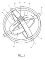
- FIG 2 this schematically illustrates an orientation guide in accordance with a second embodiment of the present invention.
- the orientation guide of figure 2 comprises a mechanical orientation guide.
- the housing comprises an outer ring 20.
- the orientation guide further comprises a coupling means (not shown) for coupling the housing ring 20 to an instrument.
- the orientation guide of figure 2 further comprises a first indicator formed as an inner indicator ring 22 which is pivotally coupled to the housing ring 20 such that it can rotate relative to the housing ring about a first axis 24.
- a second indicator in the form of a gauge 26 is coupled to the housing 22 such that angular movement of the indicator ring 22 relative to the housing 20 may be measured.
- the gauge 26 incorporates calibrated markings 28 to allow the actual angular position of the indicator to be measured by reference to an alignment mark 30 on the indicator 22.
- the gauge 26 may be fixed to the housing 20.
- the gauge 26 may be pivotally coupled to the housing 20 such that it can rotate relative to the housing 20 about a second axis 32, which is orthogonal to the first axis 24. Angular movement of the gauge ring 26 relative to the housing 20 about the second axis 32 is indicated by movement of the gauge ring 26 relative to alignment marks 34 on the indicator ring 22.
- the orientation guide should be coupled to the instrument such that the gauge ring 26 is positioned between alignment marks 34 on the indicator ring 22 when the cup which is coupled to the instrument is in the correct rotational position.
- the coupling of the orientation guide to the instrument should be such that the varus-valgus angle indicated by the calibration marks 28 correspond to the actual varus-valgus angle of the instrument (and hence the implanted cup).
- the indicator ring 22 is weighted such that the alignment marks 30 and 34 are uppermost (that is, the indicator ring 22 lies in a vertical plane).
- the gauge ring 26 is weighted so that is lies in a vertical plane so as to allow the gauge ring 26 to lie within alignment marks 34 when the instrument is in a neutral angular position about the longitudinal axis of the instrument (neutral roll).
- pitching of the instrument represents a change in the varus-valgus angle of the cup.
- Rolling of the instrument about its longitudinal axis corresponds to rotation of the cup within the reamed acetabulum. Both pitching and rolling of the instrument result in a measurable shift in the point at which indicator ring 22 and gauge ring 26 cross.
Landscapes
- Health & Medical Sciences (AREA)
- Orthopedic Medicine & Surgery (AREA)
- Life Sciences & Earth Sciences (AREA)
- Transplantation (AREA)
- Oral & Maxillofacial Surgery (AREA)
- Surgery (AREA)
- Engineering & Computer Science (AREA)
- Biomedical Technology (AREA)
- Heart & Thoracic Surgery (AREA)
- Veterinary Medicine (AREA)
- Public Health (AREA)
- Animal Behavior & Ethology (AREA)
- General Health & Medical Sciences (AREA)
- Physical Education & Sports Medicine (AREA)
- Vascular Medicine (AREA)
- Nuclear Medicine, Radiotherapy & Molecular Imaging (AREA)
- Cardiology (AREA)
- Dentistry (AREA)
- Medical Informatics (AREA)
- Molecular Biology (AREA)
- Biophysics (AREA)
- Prostheses (AREA)
- Surgical Instruments (AREA)
Claims (9)
- Orientierungsführung, umfassend:ein Gehäuse (20), das gestaltet ist, um mit einem chirurgischen Instrument zu koppeln;eine erste Anzeigeeinrichtung (22), die mit dem Gehäuse (20) schwenkbar gekoppelt ist, sodass die erste Anzeigeeinrichtung (22) relativ zum Gehäuse (20) um eine erste Achse (24) drehen kann, um ihre Winkelposition um die erste Achse (24) relativ zu einer vertikalen Achse unabhängig von Bewegung des Gehäuses (20) beizubehalten; undeine zweite Anzeigeeinrichtung (26), die die erste Anzeigeeinrichtung (22) umgibt und mit dem Gehäuse (20) schwenkbar gekoppelt ist, sodass die zweite Anzeigeeinrichtung (26) relativ zum Gehäuse (20) um eine zweite Achse (32) orthogonal zur ersten Achse (24) drehen kann, um ihre Winkelposition um die zweite Achse (32) relativ zur vertikalen Achse unabhängig von Bewegung des Gehäuses (20) beizubehalten;wobei die Winkelposition des Gehäuses (20) um die ersten und zweiten Achsen (24, 32) durch die Position der ersten Anzeigeeinrichtung (22) relativ zur zweiten Anzeigeeinrichtung (26) angezeigt wird; dadurch gekennzeichnet, dass die ersten und zweiten Anzeigeeinrichtungen (22, 26) so beschwert sind, dass sie deren Winkelposition um deren jeweiligen Achsen (24, 32) relativ zur vertikalen Achse unabhängig von Bewegung des Gehäuses (20) beibehalten.
- Orientierungsführung nach Anspruch 1, wobei mindestens eine der ersten und zweiten Anzeigeeinrichtungen (22, 26) einen Maßstab (28, 30, 34) umfasst, sodass die Position der ersten Anzeigeeinrichtung (22) relativ zur zweiten Anzeigeeinrichtung (26) um mindestens eine der ersten und zweiten Achsen (24, 32) gemessen werden kann.
- Orientierungsführung nach Anspruch 1 oder Anspruch 2, wobei die erste Anzeigeeinrichtung (22) einen ersten Ring (22) umfasst.
- Orientierungsführung nach Anspruch 3, wobei die zweite Anzeigeeinrichtung (26) einen zweiten Ring (26) umfasst, der den ersten Ring (22) umgibt.
- Orientierungsführung nach Anspruch 4, wobei das Gehäuse (20) einen dritten Ring (20) umfasst, der den zweiten Ring (26) umgibt, wobei die ersten (22), zweiten (26) und dritten (20) Ringe konzentrisch angeordnet sind.
- Orientierungsführung nach Anspruch 4 oder Anspruch 5, wobei die Winkelposition des Gehäuses (20) um die ersten und zweiten Achsen (24, 32) durch die Position um die ersten und zweiten Ringe (22, 26), wo sich die Ringe (22, 26) kreuzen, angezeigt wird.
- Orientierungsführung nach Anspruch 6, wobei der zweite Ring (26) einen Maßstab (28) umfasst, der sich um den Umfang des Ringes (26) erstreckt, und der erste Ring (22) eine erste Ausrichtmarkierung (30) umfasst, wobei die Winkelposition des Gehäuses (20) um die erste Achse (24) durch die Position der ersten Ausrichtmarkierung (30) relativ zum Maßstab (28) angezeigt wird.
- Orientierungsführung nach Anspruch 6 oder Anspruch 7, wobei der erste Ring (22) ferner zweite und dritte Ausrichtmarkierungen (34) umfasst, wobei die Winkelposition des Gehäuses (20) um die zweite Achse (32) durch die Position des zweiten Ringes (56) relativ zu den zweiten und dritten Ausrichtmarkierungen (34) angezeigt wird.
- Orientierungsführung nach Anspruch 8, wobei eine erste festgelegte Winkelposition des Gehäuses (20) um die zweite Achse (32) durch den zweiten Ring (26), der sich zwischen den zweiten und dritten Ausrichtmarkierungen (34) befindet, angezeigt wird.
Applications Claiming Priority (2)
| Application Number | Priority Date | Filing Date | Title |
|---|---|---|---|
| GBGB0900830.1A GB0900830D0 (en) | 2009-01-20 | 2009-01-20 | Orientation guide |
| PCT/GB2009/051740 WO2010084299A2 (en) | 2009-01-20 | 2009-12-18 | Orientation guide |
Publications (2)
| Publication Number | Publication Date |
|---|---|
| EP2378985A2 EP2378985A2 (de) | 2011-10-26 |
| EP2378985B1 true EP2378985B1 (de) | 2014-11-05 |
Family
ID=40446000
Family Applications (1)
| Application Number | Title | Priority Date | Filing Date |
|---|---|---|---|
| EP09801536.5A Not-in-force EP2378985B1 (de) | 2009-01-20 | 2009-12-18 | Orientierungsführung |
Country Status (7)
| Country | Link |
|---|---|
| US (1) | US9084687B2 (de) |
| EP (1) | EP2378985B1 (de) |
| JP (1) | JP5558491B2 (de) |
| CN (1) | CN102292038B (de) |
| AU (1) | AU2009338517B2 (de) |
| GB (1) | GB0900830D0 (de) |
| WO (1) | WO2010084299A2 (de) |
Families Citing this family (11)
| Publication number | Priority date | Publication date | Assignee | Title |
|---|---|---|---|---|
| CN104771230B (zh) * | 2015-04-27 | 2017-03-15 | 中南大学湘雅医院 | 一种髋臼外杯植入标记仪及标记方法 |
| US10874407B2 (en) * | 2015-05-27 | 2020-12-29 | Zimmer, Inc. | Bone depth stop apparatus and method |
| GB201522723D0 (en) * | 2015-12-23 | 2016-02-03 | Depuy Ireland Ltd | Device for detecting deformation of a hollow component |
| WO2017120434A2 (en) * | 2016-01-08 | 2017-07-13 | Boston Scientific Scimed, Inc., | Devices and methods for guiding a surgical instrument |
| US10610325B2 (en) * | 2017-02-16 | 2020-04-07 | Canon U.S.A., Inc. | Medical guidance apparatus |
| CN108553146A (zh) * | 2018-05-15 | 2018-09-21 | 王小华 | 一种膝盖软骨微骨折手术的定位装置 |
| CN108542467B (zh) * | 2018-05-15 | 2020-04-14 | 绍兴盖科生物科技有限公司 | 一种骨科用于膝关节软骨的修复装置 |
| DE102019200591B4 (de) | 2019-01-17 | 2022-02-24 | Siemens Healthcare Gmbh | Schädelklemmvorrichtung zur Fixierung und Ausrichtung eines Kopfes eines Patienten für einen medizinischen Eingriff und medizinisches Bildgebungssystem |
| CN110432961B (zh) * | 2019-07-19 | 2021-07-09 | 温州医科大学附属第一医院 | 一种胫骨平台塌陷骨折块微创复位器 |
| CN110432960B (zh) * | 2019-07-19 | 2021-07-13 | 温州医科大学附属第一医院 | 一种用于复位塌陷骨折块的顶起器 |
| CN115137498B (zh) * | 2022-06-30 | 2026-04-07 | 武汉联影智融医疗科技有限公司 | 定位指示器位置调节装置及系统 |
Family Cites Families (14)
| Publication number | Priority date | Publication date | Assignee | Title |
|---|---|---|---|---|
| US1294710A (en) * | 1918-03-14 | 1919-02-18 | Theodore Roland | Inclinometer and compass combined. |
| US3769710A (en) * | 1969-04-01 | 1973-11-06 | R Reister | Electronic celestial navigation means |
| US3673688A (en) * | 1970-02-11 | 1972-07-04 | Holosonics Inc | Geological mechanical computer |
| US3956831A (en) * | 1975-02-26 | 1976-05-18 | Sibley Scott F | Attitude meter with rotatable arcuate scale |
| DE19651476C2 (de) * | 1996-12-11 | 2001-02-15 | Nils Sappok | Geologenkompaß |
| JP3075998B2 (ja) * | 1997-03-21 | 2000-08-14 | 有限会社日本整形機器 | 人工関節取付器 |
| DE19716781A1 (de) | 1997-04-22 | 1998-10-29 | Klaus Rebbe | Dreidimensional anzeigende Wasserwaagenlibelle |
| US6302890B1 (en) * | 2000-03-16 | 2001-10-16 | Leone Innovations Corporation | Pelvic alignment assembly |
| JP4125059B2 (ja) | 2002-07-11 | 2008-07-23 | 株式会社アミテック | 多軸傾斜検出装置 |
| US8764758B2 (en) * | 2003-07-24 | 2014-07-01 | San-tech Surgical Sàrl | Orientation device for surgical implement |
| BRPI0416559A (pt) * | 2003-11-12 | 2007-01-23 | Int Patent Owners Cayman Ltd | calibre para utilização em um procedimento cirúrgico |
| US20110071537A1 (en) * | 2004-03-31 | 2011-03-24 | Yoshio Koga | Intramedullary Rod for Assisting Total Knee Joint Replacing Operation and Method for Controle Operation Using the Rod |
| CN2726562Y (zh) * | 2004-04-20 | 2005-09-21 | 刘尚礼 | 髋臼杯植入定位装置 |
| UA26162U (en) | 2007-04-03 | 2007-09-10 | Movable device for determining an inclination of an object |
-
2009
- 2009-01-20 GB GBGB0900830.1A patent/GB0900830D0/en not_active Ceased
- 2009-12-18 AU AU2009338517A patent/AU2009338517B2/en not_active Ceased
- 2009-12-18 CN CN200980155393.0A patent/CN102292038B/zh not_active Expired - Fee Related
- 2009-12-18 EP EP09801536.5A patent/EP2378985B1/de not_active Not-in-force
- 2009-12-18 WO PCT/GB2009/051740 patent/WO2010084299A2/en not_active Ceased
- 2009-12-18 JP JP2011545787A patent/JP5558491B2/ja not_active Expired - Fee Related
- 2009-12-18 US US13/145,357 patent/US9084687B2/en not_active Expired - Fee Related
Also Published As
| Publication number | Publication date |
|---|---|
| WO2010084299A2 (en) | 2010-07-29 |
| GB0900830D0 (en) | 2009-03-04 |
| AU2009338517A1 (en) | 2011-07-07 |
| JP5558491B2 (ja) | 2014-07-23 |
| US9084687B2 (en) | 2015-07-21 |
| US20120035612A1 (en) | 2012-02-09 |
| AU2009338517B2 (en) | 2015-02-12 |
| CN102292038B (zh) | 2014-06-25 |
| EP2378985A2 (de) | 2011-10-26 |
| JP2012515568A (ja) | 2012-07-12 |
| WO2010084299A3 (en) | 2010-09-10 |
| CN102292038A (zh) | 2011-12-21 |
Similar Documents
| Publication | Publication Date | Title |
|---|---|---|
| US9084687B2 (en) | Orientation guide | |
| JP2012515568A5 (de) | ||
| AU2010244214B2 (en) | Alignment guide | |
| US8764758B2 (en) | Orientation device for surgical implement | |
| US20080132903A1 (en) | Goniometer for measuring artificial acetabular cup angles and method for measuring thereof using the goniometer | |
| US10420568B2 (en) | Inside-out guide for hip replacement method | |
| US10238509B2 (en) | Telescopic guide for hip replacement method | |
| US20180250144A1 (en) | Acetabular cup prosthesis positioning instrument and method | |
| US20140303631A1 (en) | Method and apparatus for determining the orientation and/or position of an object during a medical procedure | |
| CN108366861B (zh) | 用于对准髋臼杯的设备 | |
| CN112351745B (zh) | 股骨颈切除夹具 | |
| CN105307599A (zh) | 髋臼植入物对准装置及方法 | |
| CN100407990C (zh) | 用于外科手术操作的计量仪器 | |
| WO2019202320A1 (en) | Surgical-tool angular measurement device | |
| NL2020309B1 (en) | Positioning aid in particular for positioning an acetabular prosthetic component | |
| CN213607210U (zh) | 髋关节置换手术的髋臼假体个性化组配的角度测量装置 |
Legal Events
| Date | Code | Title | Description |
|---|---|---|---|
| PUAI | Public reference made under article 153(3) epc to a published international application that has entered the european phase |
Free format text: ORIGINAL CODE: 0009012 |
|
| 17P | Request for examination filed |
Effective date: 20110607 |
|
| AK | Designated contracting states |
Kind code of ref document: A2 Designated state(s): AT BE BG CH CY CZ DE DK EE ES FI FR GB GR HR HU IE IS IT LI LT LU LV MC MK MT NL NO PL PT RO SE SI SK SM TR |
|
| DAX | Request for extension of the european patent (deleted) | ||
| GRAP | Despatch of communication of intention to grant a patent |
Free format text: ORIGINAL CODE: EPIDOSNIGR1 |
|
| INTG | Intention to grant announced |
Effective date: 20140606 |
|
| GRAS | Grant fee paid |
Free format text: ORIGINAL CODE: EPIDOSNIGR3 |
|
| GRAA | (expected) grant |
Free format text: ORIGINAL CODE: 0009210 |
|
| AK | Designated contracting states |
Kind code of ref document: B1 Designated state(s): AT BE BG CH CY CZ DE DK EE ES FI FR GB GR HR HU IE IS IT LI LT LU LV MC MK MT NL NO PL PT RO SE SI SK SM TR |
|
| REG | Reference to a national code |
Ref country code: GB Ref legal event code: FG4D |
|
| REG | Reference to a national code |
Ref country code: CH Ref legal event code: EP Ref country code: CH Ref legal event code: NV Representative=s name: E. BLUM AND CO. AG PATENT- UND MARKENANWAELTE , CH |
|
| REG | Reference to a national code |
Ref country code: AT Ref legal event code: REF Ref document number: 694161 Country of ref document: AT Kind code of ref document: T Effective date: 20141115 |
|
| REG | Reference to a national code |
Ref country code: IE Ref legal event code: FG4D |
|
| REG | Reference to a national code |
Ref country code: DE Ref legal event code: R096 Ref document number: 602009027616 Country of ref document: DE Effective date: 20141218 |
|
| REG | Reference to a national code |
Ref country code: AT Ref legal event code: MK05 Ref document number: 694161 Country of ref document: AT Kind code of ref document: T Effective date: 20141105 |
|
| REG | Reference to a national code |
Ref country code: NL Ref legal event code: VDEP Effective date: 20141105 |
|
| REG | Reference to a national code |
Ref country code: LT Ref legal event code: MG4D |
|
| PG25 | Lapsed in a contracting state [announced via postgrant information from national office to epo] |
Ref country code: NL Free format text: LAPSE BECAUSE OF FAILURE TO SUBMIT A TRANSLATION OF THE DESCRIPTION OR TO PAY THE FEE WITHIN THE PRESCRIBED TIME-LIMIT Effective date: 20141105 Ref country code: NO Free format text: LAPSE BECAUSE OF FAILURE TO SUBMIT A TRANSLATION OF THE DESCRIPTION OR TO PAY THE FEE WITHIN THE PRESCRIBED TIME-LIMIT Effective date: 20150205 Ref country code: FI Free format text: LAPSE BECAUSE OF FAILURE TO SUBMIT A TRANSLATION OF THE DESCRIPTION OR TO PAY THE FEE WITHIN THE PRESCRIBED TIME-LIMIT Effective date: 20141105 Ref country code: ES Free format text: LAPSE BECAUSE OF FAILURE TO SUBMIT A TRANSLATION OF THE DESCRIPTION OR TO PAY THE FEE WITHIN THE PRESCRIBED TIME-LIMIT Effective date: 20141105 Ref country code: IS Free format text: LAPSE BECAUSE OF FAILURE TO SUBMIT A TRANSLATION OF THE DESCRIPTION OR TO PAY THE FEE WITHIN THE PRESCRIBED TIME-LIMIT Effective date: 20150305 Ref country code: LT Free format text: LAPSE BECAUSE OF FAILURE TO SUBMIT A TRANSLATION OF THE DESCRIPTION OR TO PAY THE FEE WITHIN THE PRESCRIBED TIME-LIMIT Effective date: 20141105 Ref country code: PT Free format text: LAPSE BECAUSE OF FAILURE TO SUBMIT A TRANSLATION OF THE DESCRIPTION OR TO PAY THE FEE WITHIN THE PRESCRIBED TIME-LIMIT Effective date: 20150305 |
|
| PG25 | Lapsed in a contracting state [announced via postgrant information from national office to epo] |
Ref country code: LV Free format text: LAPSE BECAUSE OF FAILURE TO SUBMIT A TRANSLATION OF THE DESCRIPTION OR TO PAY THE FEE WITHIN THE PRESCRIBED TIME-LIMIT Effective date: 20141105 Ref country code: GR Free format text: LAPSE BECAUSE OF FAILURE TO SUBMIT A TRANSLATION OF THE DESCRIPTION OR TO PAY THE FEE WITHIN THE PRESCRIBED TIME-LIMIT Effective date: 20150206 Ref country code: CY Free format text: LAPSE BECAUSE OF FAILURE TO SUBMIT A TRANSLATION OF THE DESCRIPTION OR TO PAY THE FEE WITHIN THE PRESCRIBED TIME-LIMIT Effective date: 20141105 Ref country code: AT Free format text: LAPSE BECAUSE OF FAILURE TO SUBMIT A TRANSLATION OF THE DESCRIPTION OR TO PAY THE FEE WITHIN THE PRESCRIBED TIME-LIMIT Effective date: 20141105 Ref country code: SE Free format text: LAPSE BECAUSE OF FAILURE TO SUBMIT A TRANSLATION OF THE DESCRIPTION OR TO PAY THE FEE WITHIN THE PRESCRIBED TIME-LIMIT Effective date: 20141105 Ref country code: PL Free format text: LAPSE BECAUSE OF FAILURE TO SUBMIT A TRANSLATION OF THE DESCRIPTION OR TO PAY THE FEE WITHIN THE PRESCRIBED TIME-LIMIT Effective date: 20141105 Ref country code: HR Free format text: LAPSE BECAUSE OF FAILURE TO SUBMIT A TRANSLATION OF THE DESCRIPTION OR TO PAY THE FEE WITHIN THE PRESCRIBED TIME-LIMIT Effective date: 20141105 |
|
| PG25 | Lapsed in a contracting state [announced via postgrant information from national office to epo] |
Ref country code: BE Free format text: LAPSE BECAUSE OF NON-PAYMENT OF DUE FEES Effective date: 20141231 |
|
| PG25 | Lapsed in a contracting state [announced via postgrant information from national office to epo] |
Ref country code: SK Free format text: LAPSE BECAUSE OF FAILURE TO SUBMIT A TRANSLATION OF THE DESCRIPTION OR TO PAY THE FEE WITHIN THE PRESCRIBED TIME-LIMIT Effective date: 20141105 Ref country code: RO Free format text: LAPSE BECAUSE OF FAILURE TO SUBMIT A TRANSLATION OF THE DESCRIPTION OR TO PAY THE FEE WITHIN THE PRESCRIBED TIME-LIMIT Effective date: 20141105 Ref country code: CZ Free format text: LAPSE BECAUSE OF FAILURE TO SUBMIT A TRANSLATION OF THE DESCRIPTION OR TO PAY THE FEE WITHIN THE PRESCRIBED TIME-LIMIT Effective date: 20141105 Ref country code: EE Free format text: LAPSE BECAUSE OF FAILURE TO SUBMIT A TRANSLATION OF THE DESCRIPTION OR TO PAY THE FEE WITHIN THE PRESCRIBED TIME-LIMIT Effective date: 20141105 Ref country code: DK Free format text: LAPSE BECAUSE OF FAILURE TO SUBMIT A TRANSLATION OF THE DESCRIPTION OR TO PAY THE FEE WITHIN THE PRESCRIBED TIME-LIMIT Effective date: 20141105 |
|
| REG | Reference to a national code |
Ref country code: DE Ref legal event code: R097 Ref document number: 602009027616 Country of ref document: DE |
|
| PG25 | Lapsed in a contracting state [announced via postgrant information from national office to epo] |
Ref country code: MC Free format text: LAPSE BECAUSE OF FAILURE TO SUBMIT A TRANSLATION OF THE DESCRIPTION OR TO PAY THE FEE WITHIN THE PRESCRIBED TIME-LIMIT Effective date: 20141105 |
|
| PLBE | No opposition filed within time limit |
Free format text: ORIGINAL CODE: 0009261 |
|
| STAA | Information on the status of an ep patent application or granted ep patent |
Free format text: STATUS: NO OPPOSITION FILED WITHIN TIME LIMIT |
|
| 26N | No opposition filed |
Effective date: 20150806 |
|
| PG25 | Lapsed in a contracting state [announced via postgrant information from national office to epo] |
Ref country code: IT Free format text: LAPSE BECAUSE OF FAILURE TO SUBMIT A TRANSLATION OF THE DESCRIPTION OR TO PAY THE FEE WITHIN THE PRESCRIBED TIME-LIMIT Effective date: 20141105 |
|
| PG25 | Lapsed in a contracting state [announced via postgrant information from national office to epo] |
Ref country code: SI Free format text: LAPSE BECAUSE OF FAILURE TO SUBMIT A TRANSLATION OF THE DESCRIPTION OR TO PAY THE FEE WITHIN THE PRESCRIBED TIME-LIMIT Effective date: 20141105 |
|
| PG25 | Lapsed in a contracting state [announced via postgrant information from national office to epo] |
Ref country code: SM Free format text: LAPSE BECAUSE OF FAILURE TO SUBMIT A TRANSLATION OF THE DESCRIPTION OR TO PAY THE FEE WITHIN THE PRESCRIBED TIME-LIMIT Effective date: 20141105 |
|
| PG25 | Lapsed in a contracting state [announced via postgrant information from national office to epo] |
Ref country code: BG Free format text: LAPSE BECAUSE OF FAILURE TO SUBMIT A TRANSLATION OF THE DESCRIPTION OR TO PAY THE FEE WITHIN THE PRESCRIBED TIME-LIMIT Effective date: 20141105 |
|
| PG25 | Lapsed in a contracting state [announced via postgrant information from national office to epo] |
Ref country code: HU Free format text: LAPSE BECAUSE OF FAILURE TO SUBMIT A TRANSLATION OF THE DESCRIPTION OR TO PAY THE FEE WITHIN THE PRESCRIBED TIME-LIMIT; INVALID AB INITIO Effective date: 20091218 Ref country code: LU Free format text: LAPSE BECAUSE OF NON-PAYMENT OF DUE FEES Effective date: 20141218 Ref country code: TR Free format text: LAPSE BECAUSE OF FAILURE TO SUBMIT A TRANSLATION OF THE DESCRIPTION OR TO PAY THE FEE WITHIN THE PRESCRIBED TIME-LIMIT Effective date: 20141105 Ref country code: MT Free format text: LAPSE BECAUSE OF FAILURE TO SUBMIT A TRANSLATION OF THE DESCRIPTION OR TO PAY THE FEE WITHIN THE PRESCRIBED TIME-LIMIT Effective date: 20141105 |
|
| REG | Reference to a national code |
Ref country code: FR Ref legal event code: PLFP Year of fee payment: 8 |
|
| REG | Reference to a national code |
Ref country code: FR Ref legal event code: PLFP Year of fee payment: 9 |
|
| PG25 | Lapsed in a contracting state [announced via postgrant information from national office to epo] |
Ref country code: MK Free format text: LAPSE BECAUSE OF FAILURE TO SUBMIT A TRANSLATION OF THE DESCRIPTION OR TO PAY THE FEE WITHIN THE PRESCRIBED TIME-LIMIT Effective date: 20141105 |
|
| PGFP | Annual fee paid to national office [announced via postgrant information from national office to epo] |
Ref country code: IE Payment date: 20191209 Year of fee payment: 11 Ref country code: DE Payment date: 20191203 Year of fee payment: 11 |
|
| PGFP | Annual fee paid to national office [announced via postgrant information from national office to epo] |
Ref country code: FR Payment date: 20191113 Year of fee payment: 11 |
|
| PGFP | Annual fee paid to national office [announced via postgrant information from national office to epo] |
Ref country code: CH Payment date: 20191213 Year of fee payment: 11 |
|
| PGFP | Annual fee paid to national office [announced via postgrant information from national office to epo] |
Ref country code: GB Payment date: 20191219 Year of fee payment: 11 |
|
| REG | Reference to a national code |
Ref country code: DE Ref legal event code: R119 Ref document number: 602009027616 Country of ref document: DE |
|
| REG | Reference to a national code |
Ref country code: CH Ref legal event code: PL |
|
| GBPC | Gb: european patent ceased through non-payment of renewal fee |
Effective date: 20201218 |
|
| PG25 | Lapsed in a contracting state [announced via postgrant information from national office to epo] |
Ref country code: FR Free format text: LAPSE BECAUSE OF NON-PAYMENT OF DUE FEES Effective date: 20201231 Ref country code: IE Free format text: LAPSE BECAUSE OF NON-PAYMENT OF DUE FEES Effective date: 20201218 |
|
| PG25 | Lapsed in a contracting state [announced via postgrant information from national office to epo] |
Ref country code: DE Free format text: LAPSE BECAUSE OF NON-PAYMENT OF DUE FEES Effective date: 20210701 Ref country code: GB Free format text: LAPSE BECAUSE OF NON-PAYMENT OF DUE FEES Effective date: 20201218 Ref country code: CH Free format text: LAPSE BECAUSE OF NON-PAYMENT OF DUE FEES Effective date: 20201231 Ref country code: LI Free format text: LAPSE BECAUSE OF NON-PAYMENT OF DUE FEES Effective date: 20201231 |