EP2378720B1 - Extranet networking method, system and device for multicast virtual private network - Google Patents
Extranet networking method, system and device for multicast virtual private network Download PDFInfo
- Publication number
- EP2378720B1 EP2378720B1 EP09836058.9A EP09836058A EP2378720B1 EP 2378720 B1 EP2378720 B1 EP 2378720B1 EP 09836058 A EP09836058 A EP 09836058A EP 2378720 B1 EP2378720 B1 EP 2378720B1
- Authority
- EP
- European Patent Office
- Prior art keywords
- multicast
- vpn
- instance
- source
- group address
- Prior art date
- Legal status (The legal status is an assumption and is not a legal conclusion. Google has not performed a legal analysis and makes no representation as to the accuracy of the status listed.)
- Active
Links
Images


Classifications
-
- H—ELECTRICITY
- H04—ELECTRIC COMMUNICATION TECHNIQUE
- H04L—TRANSMISSION OF DIGITAL INFORMATION, e.g. TELEGRAPHIC COMMUNICATION
- H04L45/00—Routing or path finding of packets in data switching networks
- H04L45/16—Multipoint routing
-
- H—ELECTRICITY
- H04—ELECTRIC COMMUNICATION TECHNIQUE
- H04L—TRANSMISSION OF DIGITAL INFORMATION, e.g. TELEGRAPHIC COMMUNICATION
- H04L12/00—Data switching networks
- H04L12/28—Data switching networks characterised by path configuration, e.g. LAN [Local Area Networks] or WAN [Wide Area Networks]
- H04L12/46—Interconnection of networks
- H04L12/4641—Virtual LANs, VLANs, e.g. virtual private networks [VPN]
-
- H—ELECTRICITY
- H04—ELECTRIC COMMUNICATION TECHNIQUE
- H04L—TRANSMISSION OF DIGITAL INFORMATION, e.g. TELEGRAPHIC COMMUNICATION
- H04L45/00—Routing or path finding of packets in data switching networks
- H04L45/50—Routing or path finding of packets in data switching networks using label swapping, e.g. multi-protocol label switch [MPLS]
Definitions
- the present invention relates to the field of communications technologies, and in particular, to a method, a system, and an apparatus for extranet networking of a multicast Virtual Private Network (VPN).
- VPN Virtual Private Network
- IP multicast refers to that in an IP network, a data packet is sent to a certain determined node subset in the network by using a best-effort scheme, and the node subset is referred to as a multicast group.
- a source host sends only one piece of data, a destination address in the piece of data is a multicast group address, all receivers in the multicast group may receive the same data copy, and only hosts in the multicast group may receive the data, while other hosts outside the multicast group cannot receive the data.
- a VPN may divide an existing IP network into logically isolated networks.
- the VPN is formed of a customer edge (CE), a provider edge (PE), and a provider (P, namely, a service provider network backbone router).
- the CE is directly connected to a service provider (SP) network, exclusively belongs to a certain VPN, only serves the exclusive VPN, and only maintains a set of forwarding mechanism, and the CE may be a router or a switch, and may also be a host;
- the PE is directly connected to the CE, is also connected to a public network and a VPN network, and serves a plurality of VPNs simultaneously; and the P is not directly connected to the CE.
- the PE and the P are managed only by the SP, and the CE is managed only by a user, unless the customer entrusts the SP with the management right.
- a PE may be connected to a plurality of CEs, and a CE may also be connected to a plurality of PEs belonging to the same SP or different SPs.
- On the PE information of each network must be strictly distinguished, and a set of forwarding mechanism is independently maintained for each network.
- a set of software/hardware apparatus serving the same network on the PE is collectively referred to as an instance, a plurality of instances may exist simultaneously on the PE, and the same instance may be distributed on a plurality of PEs.
- a multicast VPN solution needs to support a multicast function in an SP backbone network (a core network or a public network), and multicast data and a control message in a private network instance are transferred to a remote site of the VPN through a public network.
- a multicast instance operated in a VPN instance on a PE router is referred to as a private network multicast instance, and a multicast instance operated by a public network part of the PE router is referred to as a public network multicast instance.
- the public network multicast instance does not need to learn multicast data transferred in the private network
- the private network multicast instance does not either need to learn multicast routing information in the public network instance
- private network multicast instances are isolated from each other.
- a multicast VPN extranet networking solution may be used.
- the networking solution may be that, a source PE configures a receiver VPN multicast instance, and a Share-Group address of a receiver VPN is added to a newly configured receiver VPN multicast instance, a multicast tunnel from the newly configured receiver VPN multicast instance to the original receiver VPN multicast instance is established, and the original receiver VPN multicast instance and the newly configured receiver VPN multicast instance may communicate in an intranet manner; while on the source PE equipment, the newly configured receiver VPN multicast instance and the source VPN multicast instance realize an extranet in a local intersection manner, that is, communicate through an internal message between different VPN multicast instances on the same equipment, so as to complete the transfer of a Protocol Independent Multicast (PIM) protocol message and a multicast data message.
- PIM Protocol Independent Multicast
- a networking solution in the prior art may also be that, a receiver PE configures a source VPN multicast instance, a Share-Group address of an original source VPN is added to a newly configured source VPN multicast instance, a multicast tunnel from the newly configured source VPN multicast instance to the original source VPN multicast instance is established, and the newly configured source VPN multicast instance and the original source VPN multicast instance may communicate in an intranet manner; while on the receiver PE equipment, the newly configured source VPN multicast instance and the receiver VPN multicast instance realize an extranet in a local intersection manner, that is, communicate through an internal message between different VPN multicast instances on the same equipment, so as to complete the transfer of a PIM protocol message and a multicast data message.
- the multicast VPN extranet is realized through local private network intersection, and a multicast stream of a remote VPN site still uses a multicast tunnel of the same VPN.
- the receiver VPN multicast instance needs to receive multicast data from a plurality of different source VPNs, the receiver PE needs to additionally configure a plurality of source VPN multicast instances, while the receiver PE may not have a service of the foregoing VPN instances, and the occupation of system resources on a receiver PE router is excessively large. The same problem occurs on the source PE configuring the receiver VPN multicast instance.
- VPN multicast instances of a plurality of remote PEs for a multicast stream of the source VPN multicast instance need to be received, since each receiver VPN needs to transfer the multicast stream through its own multicast tunnel, a public network performs encapsulation and replication in a Share-Group multicast distribution tree of a plurality of receiver VPNs, and meanwhile a plurality of traffic is forwarded for a piece of multicast data, thereby increasing the network load.
- US 2008/101350 A1 discloses a method, network and service to provide multicast forwarding in a public network offering virtual private network services using multi-protocol label switching.
- Embodiments of the present invention provide a method, a system, and an apparatus for extranet networking of a multicast VPN, which alleviate the network load.
- the present invention provides a method for extranet networking of a multicast VPN, which includes:
- the present invention further provides a receiver VPN multicast instance of a multicast VPN, which includes:
- the technical solutions of the present invention have the following advantages: Because the Share-Group address of the source VPN is added to the receiver VPN multicast instance, and the multicast tunnel from the receiver VPN multicast instance to the source VPN multicast instance is established, the resource occupation of a router system is reduced, and the network load is alleviated.
- no VPN instance is additionally configured, and a Share-Group address of a source VPN is added to a receiver VPN multicast instance, so that a PIM protocol message of a receiver VPN may reach the remote source VPN, and a multicast data message of the source VPN may also reach the remote receiver VPN.
- FIG. 1 is a flow chart of a method for extranet networking of a multicast VPN according to an embodiment of the present invention, which includes the following steps:
- a VPN instance providing a multicast data source is referred to as a source VPN multicast instance, and a PE router where the source VPN multicast instance is located is referred to as a source PE; and a VPN instance in need of receiving the multicast data is referred to as a receiver VPN multicast instance, and is not located at the same VPN as the source VPN multicast instance, and a PE router where the receiver VPN multicast instance is located is referred to as a receiver PE.
- the Share-Group address of the source VPN is added to the source VPN multicast instance at the source PE side
- the Share-Group address of the source VPN is also added to the receiver VPN multicast instance, and the multicast tunnel from the receiver VPN multicast instance to the source VPN multicast instance and the MTI connected to the multicast tunnel are established.
- a forwarding range of the multicast data of the source VPN multicast instance is specified.
- the specified forwarding range of the multicast data of the source VPN multicast instance is a private network group address range; and when both the receiver VPN multicast instance and the source VPN multicast instance operate in a PIM Source Specific Multicast (SSM), the specified forwarding range of the multicast data of the source VPN multicast instance is a private network source group address range.
- SSM PIM Source Specific Multicast
- forwarding ranges of extranet multicast data of different source VPNs may be specified in such forms as (Share-Group, private network group address/mask), [Share-Group, (private network source address/mask, private network group address/mask)], and [Share-Group, (discrete group address set)].
- Step 102 Send an encapsulated PIM protocol message to the MTI, forward the encapsulated PIM protocol message in a public network, and make the source VPN multicast instance generate a public network multicast data message of a Share-Group of the source VPN according to the encapsulated PIM protocol message.
- the MTI to which the encapsulated PIM protocol message is sent needs to be determined according to a private network group address or a source group address, a PIM protocol message of the receiver VPN multicast instance is encapsulated into the encapsulated PIM protocol message of a Share-Group according to the Share-Group corresponding to the MTI, and the encapsulated PIM protocol message is forwarded in the public network through a public network multicast instance.
- the source VPN multicast instance decapsulates the encapsulated PIM protocol message forwarded in the public network, and obtains the PIM protocol message of the receiver VPN multicast instance; and after obtaining the PIM protocol message of the receiver VPN multicast instance, the source VPN multicast instance encapsulates the multicast data of the source VPN according to the PIM protocol message, and sends the public network multicast data message encapsulated with the multicast data of the source VPN to the receiver VPN multicast instance through the public network.
- Step 103 Decapsulate the received public network multicast data message of the Share-Group of the source VPN, and obtain the multicast data from the source VPN multicast instance.
- the source VPN multicast instance obtains the PIM protocol message, encapsulates the multicast data into the public network multicast data message of the Share-Group of the source VPN according to the PIM protocol message, and forwards the encapsulated multicast data in the public network through the public network multicast instance.
- the receiver VPN multicast instance receives the encapsulated multicast data, decapsulates the encapsulated multicast data, and obtains the multicast data, thereby realizing the extranet networking of the multicast VPN.
- the multicast data is forwarded according to receiver VPN multicast routing if the group address or the source group address of the multicast data is in the specified forwarding range of the multicast data of the source VPN multicast instance; and the multicast data is discarded if the group address or the source group address of the multicast data is not in the specified forwarding range of the multicast data of the source VPN multicast instance.
- the embodiment of the present invention ensures isolation between VPN multicast instances.
- multicast forwarding of a remote site of a current VPN and remote sites of other source VPNs is performed through their respective different multicast tunnels of the receiver VPN multicast instances, no communication exists between the multicast tunnels, and an MTI created by each of multicast tunnels is used for sending a multicast protocol message and receiving a multicast data message; and as for the source VPN multicast instance, each receiver VPN multicast instance establishes a multicast tunnel to the source VPN, only an address space of the source VPN used for extranet forwarding is visible, and other address spaces of each VPN multicast instance are still isolated, that is, an intranet address space of the source VPN multicast instance is invisible to each receiver VPN, and the intranet address space and other extranet address spaces of all receiver VPN instances are also invisible to each other.
- the technical solution according to the embodiment of the present invention has the following advantages: Because the Share-Group address of the source VPN is added to the receiver VPN multicast instance, and the multicast tunnel from the receiver VPN multicast instance to the source VPN multicast instance is established, the resource occupation of a router system is reduced, and the network load is alleviated.
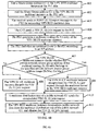
- FIG. 2A and FIG. 2B are a flow chart of another method for extranet networking of a multicast VPN according to an embodiment of the present invention.
- the method for extranet networking of a multicast VPN is applied to networking as shown in FIG. 3 , in which PE1 is a PE router where a VPN RED multicast instance is located, PE2 is a PE router where a VPN BLUE multicast instance is located, CE1 is connected to a multicast source, and CE2 is connected to a receiver.
- the method for extranet networking of a multicast VPN includes the following steps:
- the VPN RED multicast instance is a VPN instance providing a multicast data source, and the PE1 is a PE router where the VPN RED multicast instance is located. After added with the Share-Group address G1, the VPN RED multicast instance can perform data transmission with a public network.
- Step 202 Add the Share-Group address G1 to the VPN BLUE multicast instance of the PE2 side.
- the VPN BLUE multicast instance is a VPN instance in need of receiving the multicast data, and is not located at the same VPN as the VPN RED multicast instance, and the PE2 is a PE router where the VPN BLUE multicast instance is located.
- the VPN BLUE multicast instance specifies a private network group address range Gr/Mr, establishes a multicast tunnel from the VPN BLUE multicast instance to the VPN RED multicast instance, and can perform data transmission with the public network.
- the CE1 is connected to the multicast source, the CE2 is connected to the receiver; both the VPN RED multicast instance and the VPN BLUE multicast instance operate in a PIM SM; a Rendezvous Point (RP) of the VPN RED is configured at the CE1, and the CE2 is directly connected to an interface of the receiver to enable the Internet Group Management Protocol (IGMP).
- the VPN BLUE multicast instance is added with the Share-Group address G1, and specifies the private network group address range Gr/Mr at the same time.
- the VPN BLUE multicast instance may be further added with a Share-Group address G2 of the current VPN, for receiving multicast data of a remote site of the current VPN.
- Step 203 The receiver sends an IGMP (*, G) report message to the CE2 for requesting VPN RED multicast data.
- a private network group address of the IGMP (*, G) report message is G, and a private network source address of the message is vacant.
- Step 204 The CE2 sends a PIM (*, G) join request to the PE2.
- the PIM (*, G) join request is a PIM protocol message, a private network group address of the message is G, and a private network source address of the message is vacant.
- Step 205 The PE2 generates a multicast routing (*, G) entry of the VPN BLUE multicast instance.
- a private network group address of the multicast routing (*, G) entry is G, and a private network source address of the multicast routing (*, G) entry is vacant.
- Step 206 The PE2 finds that an upstream router is the PE1 according to an RP address.
- Step 207 The VPN BLUE multicast instance checks whether the private network group address of the multicast routing (*, G) entry belongs to the specified private network group address range Gr/Mr.
- step 209 is performed; and if the private network group address of the multicast routing (*, G) entry does not belong to the Gr/Mr, step 208 is performed.
- Step 208 The VPN BLUE multicast instance discards the PIM (*, G) join request.
- Step 209 The VPN BLUE multicast instance encapsulates the PIM (*, G) join request through the multicast tunnel to the VPN RED multicast instance.
- Step 210 A multicast distribution tree of a public network G1 sends the encapsulated PIM (*, G) join request.
- Step 211 The VPN RED multicast instance decapsulates public network data from the multicast distribution tree of the public network G1, and obtains the PIM (*, G) join request.
- Step 212 The VPN RED multicast instance processes the PIM (*, G) join request, and generates a multicast routing (*, G) entry.
- Step 213 The CE1 sends VPN RED multicast data (S, G) to the PE 1.
- a private network group address of the VPN RED multicast data is G, and a private network source address of the VPN RED multicast data is S.
- Step 214 The PE1 creates a multicast routing (S, G) entry.
- a private network group address of the multicast routing (S, G) entry is G
- a private network source address of the multicast routing (S, G) entry is S.
- Step 215 The VPN RED multicast instance encapsulates the VPN RED multicast data (S, G) through the multicast tunnel of the VPN RED.
- Step 216 The multicast distribution tree of the public network G1 sends the encapsulated private network multicast data (S, G) of the VPN RED.
- Step 217 The VPN BLUE multicast instance decapsulates the public network data from the multicast distribution tree of the public network G1, and obtains the VPN RED multicast data (S, G).
- Step 218 The VPN BLUE multicast instance checks whether the private network group address of the VPN RED multicast data (S, G) belongs to the specified private network group address range Gr/Mr.
- step 220 If the private network group address of the VPN RED multicast data (S, G) belongs to the specified private network group address range Gr/Mr, step 220 is performed; and if the private network group address of the VPN RED multicast data (S, G) does not belong to the specified private network group address range Gr/Mr, step 219 is performed.
- Step 219 The VPN BLUE multicast instance discards the VPN RED multicast data (S, G).
- Step 220 The VPN BLUE multicast instance creates a multicast routing (S, G) entry.
- Step 221 The VPN BLUE multicast instance forwards the VPN RED multicast data (S, G) to the CE2.
- Step 222 The receiver obtains the VPN RED multicast data (S, G) from the CE2.
- the technical solution according to the embodiment of the present invention has the following advantages: Because the Share-Group address of the source VPN is added to the receiver VPN multicast instance, the multicast tunnel from the receiver VPN multicast instance to the source VPN multicast instance is established, and it is checked whether the private network group address of the received multicast data belongs to the specified private network group address range, the isolation between the VPN multicast instances is ensured, the resource occupation of a router system is reduced, and the network load is alleviated.
- FIG. 4A and FIG.4B are a flow chart of another method for extranet networking of a multicast VPN according to an embodiment of the present invention.
- the method for extranet networking of a multicast VPN is applied to networking as shown in FIG. 3 , in which PE1 is a PE router where a VPN RED multicast instance is located, PE2 is a PE router where a VPN BLUE multicast instance is located, CE1 is connected to a multicast source, and CE2 is connected to a receiver.
- the method for extranet networking of a multicast VPN includes the following steps:
- the VPN RED multicast instance is a VPN instance providing a multicast data source, and the PE1 is a PE router where the VPN RED multicast instance is located. After added with the Share-Group address G1, the VPN RED multicast instance can perform data transmission with a public network.
- Step 402 Add the Share-Group address G1 to the VPN BLUE multicast instance at the PE2 side.
- the VPN BLUE multicast instance is a VPN instance in need of receiving the multicast data, and is not located at the same VPN as the VPN RED multicast instance, and the PE2 is a PE router where the VPN BLUE multicast instance is located.
- the VPN BLUE multicast instance is added with the Share-Group address G1, specifies a private network source group address range (Sr/Msr, Gr/Mgr), establishes a multicast tunnel from the VPN BLUE multicast instance to the VPN RED multicast instance, and can perform data transmission with the public network.
- the CE1 is connected to the multicast source
- the CE2 is connected to the receiver
- both the VPN RED multicast instance and the VPN BLUE multicast instance operate in a PIM SSM
- the CE2 is directly connected to an interface of the receiver to enable the IGMP.
- the VPN BLUE multicast instance is added with the Share-Group address G1, and specifies the private network source group address range (Sr/Msr, Gr/Mgr) at the same time.
- the VPN BLUE multicast instance may be further added with a Share-Group address G2 of the current VPN, for receiving multicast data of a remote site of the current VPN.
- Step 403 The receiver sends an IGMP (S, G) report message to the CE2 for requesting VPN RED multicast data.
- a private network group address of the IGMP (S, G) report message is G
- a private network source address of the IGMP (S, G) report message is S.
- Step 404 The CE2 sends a PIM (S, G) join request to the PE2.
- the PIM (S, G) join request is a PIM protocol message, a private network group address of the message is G, and a private network source address of the message is S.
- Step 405 The PE2 generates a multicast routing (S, G) entry of the VPN BLUE multicast instance.
- a private network group address of the multicast routing (S, G) entry is G
- a private network source address of the multicast routing (S, G) entry is S.
- Step 406 The PE2 finds that an upstream router is the PE1 according to the private network source address.
- Step 407 The VPN BLUE multicast instance checks whether the private network source group address of the multicast routing (S, G) entry belongs to the specified private network source group address range (Sr/Msr, Gr/Mgr).
- step 409 is performed; and if the private network source group address of the multicast routing (S, G) entry does not belong to the (Sr/Msr, Gr/Mgr), step 408 is performed.
- Step 408 The VPN BLUE multicast instance discards the PIM (S, G) join request.
- Step 409 The VPN BLUE multicast instance encapsulates the PIM (S, G) join request through the multicast tunnel to the VPN RED multicast instance.
- Step 410 A multicast distribution tree of a public network G1 sends the encapsulated PIM (S, G) join request.
- Step 411 The VPN RED multicast instance decapsulates public network data from the multicast distribution tree of the public network G1, and obtains the PIM (S, G) join request.
- Step 412 The VPN RED multicast instance processes the PIM (S, G) join request, and generates a multicast routing (S, G) entry.
- Step 413 The CE1 sends VPN RED multicast data (S, G) to the PE1.
- a private network group address of the VPN RED multicast data is G, and a private network source address of the VPN RED multicast data is S.
- Step 414 The VPN RED multicast instance encapsulates the VPN RED multicast data (S, G) through the multicast tunnel of the VPN RED.
- Step 415 The multicast distribution tree of the public network G1 sends the encapsulated private network multicast data (S, G) of the VPN RED.
- Step 416 The VPN BLUE multicast instance decapsulates the public network data from the multicast distribution tree of the public network G1, and obtains the VPN RED multicast data (S, G).
- Step 417 The VPN BLUE multicast instance checks whether the private network source group address of the VPN RED multicast data (S, G) belongs to the specified private network source group address range (Sr/Msr, Gr/Mgr).
- step 419 is performed; and if the private network source group address of the VPN RED multicast data (S, G) does not belong to the specified private network source group address range (Sr/Msr, Gr/Mgr), step 418 is performed.
- Step 418 The VPN BLUE multicast instance discards the VPN RED multicast data (S, G).
- Step 419 The VPN BLUE multicast instance forwards the VPN RED multicast data (S, G) to the CE2.
- Step 420 The receiver obtains the VPN RED multicast data (S, G) from the CE2.
- the technical solution according to the embodiment of the present invention has the following advantages: Because the Share-Group address of the source VPN is added to the receiver VPN multicast instance, the multicast tunnel from the receiver VPN multicast instance to the source VPN multicast instance is established, and it is checked whether the private network source group address of the received multicast data belongs to the specified private network source group address range, the isolation between the VPN multicast instances is ensured, the resource occupation of a router system is reduced, and the network load is alleviated.
- the present invention further provides a system for extranet networking of a multicast VPN, which includes a source VPN and a receiver VPN, where: the receiver VPN is configured to establish a multicast tunnel to a source VPN multicast instance and an MTI connected to the multicast tunnel according to an added Share-Group address of a source VPN; send an encapsulated PIM protocol message to the MTI, forward the encapsulated PIM protocol message in a public network, and make the source VPN multicast instance generate a public network multicast data message of a Share-Group of the source VPN according to the encapsulated PIM protocol message; and decapsulate the received public network multicast data message of the Share-Group of the source VPN, and obtain multicast data from the source VPN multicast instance.
- the receiver VPN is configured to establish a multicast tunnel to a source VPN multicast instance and an MTI connected to the multicast tunnel according to an added Share-Group address of a source VPN
- send an encapsulated PIM protocol message to the MTI, forward the encapsulated PIM protocol message
- FIG. 5 is a schematic structural diagram of a receiver VPN multicast instance according to an embodiment of the present invention.
- the receiver VPN multicast instance 500 includes an establishing module 510, a sending module 520, and an obtaining module 530.
- the establishing module 510 is configured to establish a multicast tunnel to a source VPN multicast instance and an MTI connected to the multicast tunnel according to an added Share-Group address of a source VPN.
- a VPN instance providing a multicast data source is referred to as a source VPN multicast instance, and a PE router where the source VPN multicast instance is located is referred to as a source PE; and a VPN instance in need of receiving the multicast data is referred to as a receiver VPN multicast instance, and is not located at the same VPN as the source VPN multicast instance, and a PE router where the receiver VPN multicast instance is located is referred to as a receiver PE.
- the Share-Group address of the source VPN is added to the source VPN multicast instance at the source PE side
- the Share-Group address of the source VPN is also added to the establishing module 510 of the receiver VPN multicast instance, and the multicast tunnel from the receiver VPN multicast instance to the source VPN multicast instance and the MTI connected to the multicast tunnel are established.
- the sending module 520 is configured to send an encapsulated PIM protocol message to the MTI established by the establishing module 510, forward the encapsulated PIM protocol message in a public network, and make the source VPN multicast instance generate a public network multicast data message of a Share-Group of the source VPN according to the encapsulated PIM protocol message.
- the sending module 520 sends the encapsulated PIM protocol message to a remote PE
- the MTI to which the encapsulated PIM protocol message is sent needs to be determined according to a private network group address or a source group address
- a PIM protocol message of the receiver VPN multicast instance is encapsulated into the encapsulated PIM protocol message of the Share-Group according to the Share-Group corresponding to the MTI, and the encapsulated PIM protocol message is forwarded in a public network through a public network multicast instance.
- the source VPN multicast instance decapsulates the encapsulated PIM protocol message forwarded in the public network, and obtains the PIM protocol message of the receiver VPN multicast instance; and after obtaining the PIM protocol message of the receiver VPN multicast instance, the source VPN multicast instance encapsulates the multicast data of the source VPN according to the PIM protocol message, and sends the public network multicast data message encapsulated with the multicast data of the source VPN to the receiver VPN multicast instance through the public network.
- the obtaining module 530 is configured to decapsulate the received public network multicast data message of the Share-Group of the source VPN, and obtain the multicast data from the source VPN multicast instance.
- the source VPN multicast instance obtains the PIM protocol message, encapsulates the multicast data into the public network multicast data message of the Share-Group of the source VPN according to the PIM protocol message, and forwards the encapsulated multicast data in the public network through the public network multicast instance.
- the obtaining module 530 receives the encapsulated multicast data, decapsulates the encapsulated multicast data, and obtains the multicast data, thereby realizing the extranet networking of the multicast VPN.
- the embodiment of the present invention ensures isolation between VPN multicast instances.
- multicast forwarding of a remote site of a current VPN and remote sites of other source VPNs is performed through their respective different multicast tunnels of the receiver VPN multicast instance, no communication exists between the multicast tunnels, and an MTI created by each of multicast tunnels is used for sending a multicast protocol message and receiving a multicast data message; and as for the source VPN multicast instance, each receiver VPN multicast instance establishes a multicast tunnel to the source VPN, only an address space of the source VPN used for extranet forwarding is visible, and other address spaces of each VPN multicast instance are still isolated, that is, an intranet address space of the source VPN multicast instance is invisible to each receiver VPN, and the intranet address space and other extranet address spaces of all receiver VPN instances are also invisible to each other.
- the technical solution according to the embodiment of the present invention has the following advantages. Since the Share-Group address of the source VPN is added to the receiver VPN multicast instance, and the multicast tunnel from the receiver VPN multicast instance to the source VPN multicast instance is established, the resource occupation of a router system is reduced, and the network load is alleviated.
- FIG. 6 is a schematic structural diagram of another receiver VPN multicast instance according to an embodiment of the present invention.
- the receiver VPN multicast instance 600 includes an establishing module 610, a specifying module 620, a determining module 630, a sending module 640, an obtaining module 650, a checking module 660, a forwarding module 670, and a discarding module 680.
- the establishing module 610 is configured to establish a multicast tunnel to a source VPN multicast instance and an MTI connected to the multicast tunnel according to an added Share-Group address of a source VPN.
- a VPN instance providing a multicast data source is referred to as a source VPN multicast instance, and a PE router where the source VPN multicast instance is located is referred to as a source PE; and a VPN instance in need of receiving the multicast data is referred to as a receiver VPN multicast instance, and is not located at the same VPN as the source VPN multicast instance, and a PE router where the receiver VPN multicast instance is located is referred to as a receiver PE.
- the Share-Group address of the source VPN is added to the source VPN multicast instance of the source PE side
- the Share-Group address of the source VPN is also added to the establishing module 610 of the receiver VPN multicast instance, and the multicast tunnel from the receiver VPN multicast instance to the source VPN multicast instance, and the MTI connected to the multicast tunnel are established.
- the specifying module 620 is configured to specify a forwarding range of the multicast data of the source VPN multicast instance.
- the specifying module 620 specifies the forwarding range of the multicast data of the source VPN multicast instance, and when both the receiver VPN multicast instance and the source VPN multicast instance operate in a PIM SM, the specified forwarding range of the multicast data of the source VPN multicast instance is a private network group address range; when both the receiver VPN multicast instance and the source VPN multicast instance operate in a PIM SSM, the specified forwarding range of the multicast data of the source VPN multicast instance is a private network source group address range.
- forwarding ranges of extranet multicast data of different source VPNs may be specified in such forms as (Share-Group, private network group address/mask), [Share-Group, (private network source address/mask, private network group address/mask)], and [Share-Group, (discrete group address set)].
- the determining module 630 is configured to determine the MTI to which the sending module 640 sends the PIM protocol message according to a private network group address or a source group address.
- the sending module 640 is configured to send an encapsulated PIM protocol message to the MTI established by the establishing module 610, forward the encapsulated PIM protocol message in a public network, and make the source VPN multicast instance generate a public network multicast data message of a Share-Group of the source VPN according to the encapsulated PIM protocol message.
- the sending module 640 encapsulates the PIM protocol message into the encapsulated PIM protocol message of the Share-Group according to the Share-Group corresponding to the MTI, and forward the encapsulated PIM protocol message in a public network through a public network multicast instance.
- the source VPN multicast instance decapsulates the encapsulated PIM protocol message forwarded in the public network, and obtains the PIM protocol message.
- the obtaining module 650 is configured to decapsulate the received public network multicast data message of the Share-Group of the source VPN, and obtain the multicast data from the source VPN multicast instance.
- the source VPN multicast instance obtains the PIM protocol message, encapsulates the multicast data into the public network multicast data message of the Share-Group of the source VPN according to the PIM protocol message, and forwards the encapsulated multicast data in the public network through the public network multicast instance.
- the obtaining module 650 receives the encapsulated multicast data, decapsulates the encapsulated multicast data, and obtains the multicast data.
- the checking module 660 is configured to check whether a group address or a source group address of the multicast data obtained by the obtaining module 650 is in the specified forwarding range of the multicast data of the source VPN multicast instance.
- the checking module 660 checks whether the group address or the source group address of the multicast data obtained by the obtaining module 650 is in the specified forwarding range of the multicast data of the source VPN multicast instance.
- the multicast data is forwarded according to receiver VPN multicast routing if the group address or the source group address of the multicast data is in the specified forwarding range of the multicast data of the source VPN multicast instance; and the multicast data is discarded if the group address or the source group address of the multicast data is not in the specified forwarding range of the multicast data of the source VPN multicast instance.
- the forwarding module 670 is configured to forward the multicast data according to the receiver VPN multicast routing if the checking module 660 checks that the group address or the source group address of the multicast data is in the specified forwarding range of the multicast data of the source VPN multicast instance.
- the discarding module 680 is configured to discard the multicast data if the checking module 660 checks that the group address or the source group address of the multicast data is not in the specified forwarding range of the multicast data of the source VPN multicast instance.
- the technical solution according to the embodiment of the present invention has the following advantages: Because the Share-Group address of the source VPN is added to the receiver VPN multicast instance, the multicast tunnel from the receiver VPN multicast instance to the source VPN multicast instance is established, and it is checked whether the group address or the source group address of the received multicast data is in the specified forwarding range of the multicast data of the source VPN multicast instance, the isolation between the VPN multicast instances is ensured, the resource occupation of a router system is reduced, and the network load is alleviated.
- the present invention may be implemented by hardware only or by software plus a necessary universal hardware platform. However, in most cases, using software and a necessary universal hardware platform are preferred. Based on such understandings, all or part of the technical solutions under the present invention that makes contributions to the prior art may be essentially embodied in the form of a software product.
- the software product may be stored in a storage medium.
- the software product includes a number of instructions that enable a terminal device (mobile phone, personal computer, server, or network device) to execute the method provided in each embodiment of the present invention.
Description
- The present invention relates to the field of communications technologies, and in particular, to a method, a system, and an apparatus for extranet networking of a multicast Virtual Private Network (VPN).
- Internet Protocol (IP) multicast refers to that in an IP network, a data packet is sent to a certain determined node subset in the network by using a best-effort scheme, and the node subset is referred to as a multicast group. A source host sends only one piece of data, a destination address in the piece of data is a multicast group address, all receivers in the multicast group may receive the same data copy, and only hosts in the multicast group may receive the data, while other hosts outside the multicast group cannot receive the data.
- In dependence on a virtual dedicated communication network established in a public network by an Internet service provider (ISP) and a network service provider (NSP), a VPN may divide an existing IP network into logically isolated networks.
- The VPN is formed of a customer edge (CE), a provider edge (PE), and a provider (P, namely, a service provider network backbone router). The CE is directly connected to a service provider (SP) network, exclusively belongs to a certain VPN, only serves the exclusive VPN, and only maintains a set of forwarding mechanism, and the CE may be a router or a switch, and may also be a host; the PE is directly connected to the CE, is also connected to a public network and a VPN network, and serves a plurality of VPNs simultaneously; and the P is not directly connected to the CE. The PE and the P are managed only by the SP, and the CE is managed only by a user, unless the customer entrusts the SP with the management right. A PE may be connected to a plurality of CEs, and a CE may also be connected to a plurality of PEs belonging to the same SP or different SPs. On the PE, information of each network must be strictly distinguished, and a set of forwarding mechanism is independently maintained for each network. A set of software/hardware apparatus serving the same network on the PE is collectively referred to as an instance, a plurality of instances may exist simultaneously on the PE, and the same instance may be distributed on a plurality of PEs.
- A multicast VPN solution needs to support a multicast function in an SP backbone network (a core network or a public network), and multicast data and a control message in a private network instance are transferred to a remote site of the VPN through a public network. A multicast instance operated in a VPN instance on a PE router is referred to as a private network multicast instance, and a multicast instance operated by a public network part of the PE router is referred to as a public network multicast instance. The public network multicast instance does not need to learn multicast data transferred in the private network, the private network multicast instance does not either need to learn multicast routing information in the public network instance, and private network multicast instances are isolated from each other.
- If a VPN user needs to receive multicast data of other VPN users, a multicast VPN extranet networking solution may be used. The networking solution may be that, a source PE configures a receiver VPN multicast instance, and a Share-Group address of a receiver VPN is added to a newly configured receiver VPN multicast instance, a multicast tunnel from the newly configured receiver VPN multicast instance to the original receiver VPN multicast instance is established, and the original receiver VPN multicast instance and the newly configured receiver VPN multicast instance may communicate in an intranet manner; while on the source PE equipment, the newly configured receiver VPN multicast instance and the source VPN multicast instance realize an extranet in a local intersection manner, that is, communicate through an internal message between different VPN multicast instances on the same equipment, so as to complete the transfer of a Protocol Independent Multicast (PIM) protocol message and a multicast data message. A networking solution in the prior art may also be that, a receiver PE configures a source VPN multicast instance, a Share-Group address of an original source VPN is added to a newly configured source VPN multicast instance, a multicast tunnel from the newly configured source VPN multicast instance to the original source VPN multicast instance is established, and the newly configured source VPN multicast instance and the original source VPN multicast instance may communicate in an intranet manner; while on the receiver PE equipment, the newly configured source VPN multicast instance and the receiver VPN multicast instance realize an extranet in a local intersection manner, that is, communicate through an internal message between different VPN multicast instances on the same equipment, so as to complete the transfer of a PIM protocol message and a multicast data message.
- In the implementation of the present invention, the inventor finds that at least the following problems exist in the prior art:
- In the prior art, no matter whether the source PE configures the receiver VPN multicast instance, or the receiver PE configures the source VPN multicast instance, the multicast VPN extranet is realized through local private network intersection, and a multicast stream of a remote VPN site still uses a multicast tunnel of the same VPN. If the receiver VPN multicast instance needs to receive multicast data from a plurality of different source VPNs, the receiver PE needs to additionally configure a plurality of source VPN multicast instances, while the receiver PE may not have a service of the foregoing VPN instances, and the occupation of system resources on a receiver PE router is excessively large. The same problem occurs on the source PE configuring the receiver VPN multicast instance.
- Additionally, if VPN multicast instances of a plurality of remote PEs for a multicast stream of the source VPN multicast instance need to be received, since each receiver VPN needs to transfer the multicast stream through its own multicast tunnel, a public network performs encapsulation and replication in a Share-Group multicast distribution tree of a plurality of receiver VPNs, and meanwhile a plurality of traffic is forwarded for a piece of multicast data, thereby increasing the network load.
- The internet-article "Multicast VPN Technology White Paper" (H3C Technologies Co., Ltd., http://ww.h3c.com/portal/download.do?id=648599, XP002688313) discloses that in multicast VPN, private network multicast traffic is encapsulated and transmitted through the multicast tunnels established between different sites of private networks.
-
US 2008/101350 A1 discloses a method, network and service to provide multicast forwarding in a public network offering virtual private network services using multi-protocol label switching. - Embodiments of the present invention provide a method, a system, and an apparatus for extranet networking of a multicast VPN, which alleviate the network load.
- In an embodiment, the present invention provides a method for extranet networking of a multicast VPN, which includes:
- establishing by a receiver VPN multicast instance of the multicast VPN, a multicast tunnel from the receiver VPN multicast instance to a source VPN multicast instance and a multicast tunnel interface (MTI) connected to the multicast tunnel according to an added Share-Group address of a source VPN;
- sending, by the receiver VPN multicast instance, an encapsulated PIM protocol message to the MTI, forwarding, by the receiver VPN multicast instance, the encapsulated PIM protocol message in a public network, and making, by the receiver VPN multicast instance, the source VPN multicast instance generate a public network multicast data message of a Share-Group of the source VPN according to the encapsulated PIM protocol message; and
- decapsulating, by the receiver VPN multicast instance, the received public network multicast data message of the Share-Group of the source VPN, and obtaining, by the receiver VPN multicast instance, multicast data from the source VPN multicast instance.
- In an embodiment, the present invention further provides a receiver VPN multicast instance of a multicast VPN, which includes:
- an establishing module, configured to establish a multicast tunnel from the receiver VPN multicast instance to a source VPN multicast instance and an MTI connected with the multicast tunnel according to an added Share-Group address of a source VPN;
- a sending module, configured to send an encapsulated PIM protocol message to the MTI established by the establishing module, forward the encapsulated PIM protocol message in a public network, and make the source VPN multicast instance generate a public network multicast data message of a Share-Group of the source VPN according to the encapsulated PIM protocol message; and
- an obtaining module, configured to decapsulate the received public network multicast data message of the Share-Group of the source VPN, and obtain multicast data from the source VPN multicast instance.
- The technical solutions of the present invention have the following advantages: Because the Share-Group address of the source VPN is added to the receiver VPN multicast instance, and the multicast tunnel from the receiver VPN multicast instance to the source VPN multicast instance is established, the resource occupation of a router system is reduced, and the network load is alleviated.
- To illustrate the technical solutions according to the embodiments of the present invention or in the prior art more clearly, the accompanying drawings for describing the present invention or the prior art are introduced briefly in the following. Apparently, the accompanying drawings in the following description are only some embodiments of the present invention, and person of ordinary skill in the art can derive other drawings from the accompanying drawings without creative efforts.
-
FIG. 1 is a flow chart of a method for extranet networking of a multicast VPN according to an embodiment of the present invention; -
FIG. 2A andFIG. 2B are a flow chart of another method for extranet networking of a multicast VPN according to an embodiment of the present invention; -
FIG. 3 is a schematic diagram showing networking of a method for extranet networking according to an embodiment of the present invention; -
FIG. 4A andFIG. 4B are a flow chart of another method for extranet networking of a multicast VPN according to an embodiment of the present invention; -
FIG. 5 is a schematic structural diagram of a receiver VPN multicast instance according to an embodiment of the present invention; and -
FIG. 6 is a schematic structural diagram of another receiver VPN multicast instance according to an embodiment of the present invention. - According to the embodiments of the present invention, no VPN instance is additionally configured, and a Share-Group address of a source VPN is added to a receiver VPN multicast instance, so that a PIM protocol message of a receiver VPN may reach the remote source VPN, and a multicast data message of the source VPN may also reach the remote receiver VPN.
- The technical solutions according to the embodiments of the present invention are clearly described in detail in the following with reference to the accompanying drawings. It is evident that the embodiments to be described are only a part of rather than all of the embodiments of the present invention. All other embodiments obtained by persons of ordinary skill in the art based on the embodiments of the present invention without creative efforts shall fall within the protection scope of the present invention.
-
FIG. 1 is a flow chart of a method for extranet networking of a multicast VPN according to an embodiment of the present invention, which includes the following steps: - Step 101: Establish a multicast tunnel to a source VPN multicast instance and an MTI connected to the multicast tunnel according to an added Share-Group address of a source VPN.
- In the embodiment of the present invention, a VPN instance providing a multicast data source is referred to as a source VPN multicast instance, and a PE router where the source VPN multicast instance is located is referred to as a source PE; and a VPN instance in need of receiving the multicast data is referred to as a receiver VPN multicast instance, and is not located at the same VPN as the source VPN multicast instance, and a PE router where the receiver VPN multicast instance is located is referred to as a receiver PE. After the Share-Group address of the source VPN is added to the source VPN multicast instance at the source PE side, the Share-Group address of the source VPN is also added to the receiver VPN multicast instance, and the multicast tunnel from the receiver VPN multicast instance to the source VPN multicast instance and the MTI connected to the multicast tunnel are established.
- After the Share-Group address of the source VPN is added to the receiver VPN multicast instance, a forwarding range of the multicast data of the source VPN multicast instance is specified. When both the receiver VPN multicast instance and the source VPN multicast instance operate in a PIM Sparse Mode (SM), the specified forwarding range of the multicast data of the source VPN multicast instance is a private network group address range; and when both the receiver VPN multicast instance and the source VPN multicast instance operate in a PIM Source Specific Multicast (SSM), the specified forwarding range of the multicast data of the source VPN multicast instance is a private network source group address range. According to the embodiment of the present invention, forwarding ranges of extranet multicast data of different source VPNs may be specified in such forms as (Share-Group, private network group address/mask), [Share-Group, (private network source address/mask, private network group address/mask)], and [Share-Group, (discrete group address set)].
- Step 102: Send an encapsulated PIM protocol message to the MTI, forward the encapsulated PIM protocol message in a public network, and make the source VPN multicast instance generate a public network multicast data message of a Share-Group of the source VPN according to the encapsulated PIM protocol message.
- Before the receiver VPN multicast instance sends the encapsulated PIM protocol message to a remote PE, the MTI to which the encapsulated PIM protocol message is sent needs to be determined according to a private network group address or a source group address, a PIM protocol message of the receiver VPN multicast instance is encapsulated into the encapsulated PIM protocol message of a Share-Group according to the Share-Group corresponding to the MTI, and the encapsulated PIM protocol message is forwarded in the public network through a public network multicast instance. The source VPN multicast instance decapsulates the encapsulated PIM protocol message forwarded in the public network, and obtains the PIM protocol message of the receiver VPN multicast instance; and after obtaining the PIM protocol message of the receiver VPN multicast instance, the source VPN multicast instance encapsulates the multicast data of the source VPN according to the PIM protocol message, and sends the public network multicast data message encapsulated with the multicast data of the source VPN to the receiver VPN multicast instance through the public network.
- Step 103: Decapsulate the received public network multicast data message of the Share-Group of the source VPN, and obtain the multicast data from the source VPN multicast instance.
- The source VPN multicast instance obtains the PIM protocol message, encapsulates the multicast data into the public network multicast data message of the Share-Group of the source VPN according to the PIM protocol message, and forwards the encapsulated multicast data in the public network through the public network multicast instance. The receiver VPN multicast instance receives the encapsulated multicast data, decapsulates the encapsulated multicast data, and obtains the multicast data, thereby realizing the extranet networking of the multicast VPN.
- It is checked whether a group address or a source group address of the multicast data is in the specified forwarding range of the multicast data of the source VPN multicast instance after the receiver VPN multicast instance obtains the multicast data from the source VPN multicast instance. The multicast data is forwarded according to receiver VPN multicast routing if the group address or the source group address of the multicast data is in the specified forwarding range of the multicast data of the source VPN multicast instance; and the multicast data is discarded if the group address or the source group address of the multicast data is not in the specified forwarding range of the multicast data of the source VPN multicast instance.
- The embodiment of the present invention ensures isolation between VPN multicast instances. As for receiver VPN multicast instances, multicast forwarding of a remote site of a current VPN and remote sites of other source VPNs is performed through their respective different multicast tunnels of the receiver VPN multicast instances, no communication exists between the multicast tunnels, and an MTI created by each of multicast tunnels is used for sending a multicast protocol message and receiving a multicast data message; and as for the source VPN multicast instance, each receiver VPN multicast instance establishes a multicast tunnel to the source VPN, only an address space of the source VPN used for extranet forwarding is visible, and other address spaces of each VPN multicast instance are still isolated, that is, an intranet address space of the source VPN multicast instance is invisible to each receiver VPN, and the intranet address space and other extranet address spaces of all receiver VPN instances are also invisible to each other.
- The technical solution according to the embodiment of the present invention has the following advantages: Because the Share-Group address of the source VPN is added to the receiver VPN multicast instance, and the multicast tunnel from the receiver VPN multicast instance to the source VPN multicast instance is established, the resource occupation of a router system is reduced, and the network load is alleviated.
-
FIG. 2A andFIG. 2B are a flow chart of another method for extranet networking of a multicast VPN according to an embodiment of the present invention. In this embodiment, the method for extranet networking of a multicast VPN is applied to networking as shown inFIG. 3 , in which PE1 is a PE router where a VPN RED multicast instance is located, PE2 is a PE router where a VPN BLUE multicast instance is located, CE1 is connected to a multicast source, and CE2 is connected to a receiver. The method for extranet networking of a multicast VPN includes the following steps: - Step 201: Add a Share-Group address G1 to the VPN RED multicast instance of the PE1 side.
- The VPN RED multicast instance is a VPN instance providing a multicast data source, and the PE1 is a PE router where the VPN RED multicast instance is located. After added with the Share-Group address G1, the VPN RED multicast instance can perform data transmission with a public network.
- Step 202: Add the Share-Group address G1 to the VPN BLUE multicast instance of the PE2 side.
- The VPN BLUE multicast instance is a VPN instance in need of receiving the multicast data, and is not located at the same VPN as the VPN RED multicast instance, and the PE2 is a PE router where the VPN BLUE multicast instance is located. After added with the Share-Group address G1, the VPN BLUE multicast instance specifies a private network group address range Gr/Mr, establishes a multicast tunnel from the VPN BLUE multicast instance to the VPN RED multicast instance, and can perform data transmission with the public network.
- In the embodiment of the present invention, the CE1 is connected to the multicast source, the CE2 is connected to the receiver; both the VPN RED multicast instance and the VPN BLUE multicast instance operate in a PIM SM; a Rendezvous Point (RP) of the VPN RED is configured at the CE1, and the CE2 is directly connected to an interface of the receiver to enable the Internet Group Management Protocol (IGMP). The VPN BLUE multicast instance is added with the Share-Group address G1, and specifies the private network group address range Gr/Mr at the same time. The VPN BLUE multicast instance may be further added with a Share-Group address G2 of the current VPN, for receiving multicast data of a remote site of the current VPN.
- Step 203: The receiver sends an IGMP (*, G) report message to the CE2 for requesting VPN RED multicast data.
- A private network group address of the IGMP (*, G) report message is G, and a private network source address of the message is vacant.
- Step 204: The CE2 sends a PIM (*, G) join request to the PE2.
- The PIM (*, G) join request is a PIM protocol message, a private network group address of the message is G, and a private network source address of the message is vacant.
- Step 205: The PE2 generates a multicast routing (*, G) entry of the VPN BLUE multicast instance.
- A private network group address of the multicast routing (*, G) entry is G, and a private network source address of the multicast routing (*, G) entry is vacant.
- Step 206: The PE2 finds that an upstream router is the PE1 according to an RP address.
- Step 207: The VPN BLUE multicast instance checks whether the private network group address of the multicast routing (*, G) entry belongs to the specified private network group address range Gr/Mr.
- If the private network group address of the multicast routing (*, G) entry belongs to the Gr/Mr, step 209 is performed; and if the private network group address of the multicast routing (*, G) entry does not belong to the Gr/Mr, step 208 is performed.
- Step 208: The VPN BLUE multicast instance discards the PIM (*, G) join request.
- Step 209: The VPN BLUE multicast instance encapsulates the PIM (*, G) join request through the multicast tunnel to the VPN RED multicast instance.
- Step 210: A multicast distribution tree of a public network G1 sends the encapsulated PIM (*, G) join request.
- Step 211: The VPN RED multicast instance decapsulates public network data from the multicast distribution tree of the public network G1, and obtains the PIM (*, G) join request.
- Step 212: The VPN RED multicast instance processes the PIM (*, G) join request, and generates a multicast routing (*, G) entry.
- Step 213: The CE1 sends VPN RED multicast data (S, G) to the PE 1.
- A private network group address of the VPN RED multicast data is G, and a private network source address of the VPN RED multicast data is S.
- Step 214: The PE1 creates a multicast routing (S, G) entry.
- A private network group address of the multicast routing (S, G) entry is G, and a private network source address of the multicast routing (S, G) entry is S.
- Step 215: The VPN RED multicast instance encapsulates the VPN RED multicast data (S, G) through the multicast tunnel of the VPN RED.
- Step 216: The multicast distribution tree of the public network G1 sends the encapsulated private network multicast data (S, G) of the VPN RED.
- Step 217: The VPN BLUE multicast instance decapsulates the public network data from the multicast distribution tree of the public network G1, and obtains the VPN RED multicast data (S, G).
- Step 218: The VPN BLUE multicast instance checks whether the private network group address of the VPN RED multicast data (S, G) belongs to the specified private network group address range Gr/Mr.
- If the private network group address of the VPN RED multicast data (S, G) belongs to the specified private network group address range Gr/Mr, step 220 is performed; and if the private network group address of the VPN RED multicast data (S, G) does not belong to the specified private network group address range Gr/Mr, step 219 is performed.
- Step 219: The VPN BLUE multicast instance discards the VPN RED multicast data (S, G).
- Step 220: The VPN BLUE multicast instance creates a multicast routing (S, G) entry.
- Step 221: The VPN BLUE multicast instance forwards the VPN RED multicast data (S, G) to the CE2.
- Step 222: The receiver obtains the VPN RED multicast data (S, G) from the CE2.
- The technical solution according to the embodiment of the present invention has the following advantages: Because the Share-Group address of the source VPN is added to the receiver VPN multicast instance, the multicast tunnel from the receiver VPN multicast instance to the source VPN multicast instance is established, and it is checked whether the private network group address of the received multicast data belongs to the specified private network group address range, the isolation between the VPN multicast instances is ensured, the resource occupation of a router system is reduced, and the network load is alleviated.
-
FIG. 4A andFIG.4B are a flow chart of another method for extranet networking of a multicast VPN according to an embodiment of the present invention. In this embodiment, the method for extranet networking of a multicast VPN is applied to networking as shown inFIG. 3 , in which PE1 is a PE router where a VPN RED multicast instance is located, PE2 is a PE router where a VPN BLUE multicast instance is located, CE1 is connected to a multicast source, and CE2 is connected to a receiver. The method for extranet networking of a multicast VPN includes the following steps: - Step 401: Add a Share-Group address G1 to the VPN RED multicast instance at the PE1 side.
- The VPN RED multicast instance is a VPN instance providing a multicast data source, and the PE1 is a PE router where the VPN RED multicast instance is located. After added with the Share-Group address G1, the VPN RED multicast instance can perform data transmission with a public network.
- Step 402: Add the Share-Group address G1 to the VPN BLUE multicast instance at the PE2 side.
- The VPN BLUE multicast instance is a VPN instance in need of receiving the multicast data, and is not located at the same VPN as the VPN RED multicast instance, and the PE2 is a PE router where the VPN BLUE multicast instance is located. The VPN BLUE multicast instance is added with the Share-Group address G1, specifies a private network source group address range (Sr/Msr, Gr/Mgr), establishes a multicast tunnel from the VPN BLUE multicast instance to the VPN RED multicast instance, and can perform data transmission with the public network.
- In the embodiment of the present invention, the CE1 is connected to the multicast source, the CE2 is connected to the receiver, both the VPN RED multicast instance and the VPN BLUE multicast instance operate in a PIM SSM, and the CE2 is directly connected to an interface of the receiver to enable the IGMP. The VPN BLUE multicast instance is added with the Share-Group address G1, and specifies the private network source group address range (Sr/Msr, Gr/Mgr) at the same time. The VPN BLUE multicast instance may be further added with a Share-Group address G2 of the current VPN, for receiving multicast data of a remote site of the current VPN.
- Step 403: The receiver sends an IGMP (S, G) report message to the CE2 for requesting VPN RED multicast data.
- A private network group address of the IGMP (S, G) report message is G, and a private network source address of the IGMP (S, G) report message is S.
- Step 404: The CE2 sends a PIM (S, G) join request to the PE2.
- The PIM (S, G) join request is a PIM protocol message, a private network group address of the message is G, and a private network source address of the message is S.
- Step 405: The PE2 generates a multicast routing (S, G) entry of the VPN BLUE multicast instance.
- A private network group address of the multicast routing (S, G) entry is G, and a private network source address of the multicast routing (S, G) entry is S.
- Step 406: The PE2 finds that an upstream router is the PE1 according to the private network source address.
- Step 407: The VPN BLUE multicast instance checks whether the private network source group address of the multicast routing (S, G) entry belongs to the specified private network source group address range (Sr/Msr, Gr/Mgr).
- If the private network source group address of the multicast routing (S, G) entry belongs to the (Sr/Msr, Gr/Mgr),
step 409 is performed; and if the private network source group address of the multicast routing (S, G) entry does not belong to the (Sr/Msr, Gr/Mgr),step 408 is performed. - Step 408: The VPN BLUE multicast instance discards the PIM (S, G) join request.
- Step 409: The VPN BLUE multicast instance encapsulates the PIM (S, G) join request through the multicast tunnel to the VPN RED multicast instance.
- Step 410: A multicast distribution tree of a public network G1 sends the encapsulated PIM (S, G) join request.
- Step 411: The VPN RED multicast instance decapsulates public network data from the multicast distribution tree of the public network G1, and obtains the PIM (S, G) join request.
- Step 412: The VPN RED multicast instance processes the PIM (S, G) join request, and generates a multicast routing (S, G) entry.
- Step 413: The CE1 sends VPN RED multicast data (S, G) to the PE1.
- A private network group address of the VPN RED multicast data is G, and a private network source address of the VPN RED multicast data is S.
- Step 414: The VPN RED multicast instance encapsulates the VPN RED multicast data (S, G) through the multicast tunnel of the VPN RED.
- Step 415: The multicast distribution tree of the public network G1 sends the encapsulated private network multicast data (S, G) of the VPN RED.
- Step 416: The VPN BLUE multicast instance decapsulates the public network data from the multicast distribution tree of the public network G1, and obtains the VPN RED multicast data (S, G).
- Step 417: The VPN BLUE multicast instance checks whether the private network source group address of the VPN RED multicast data (S, G) belongs to the specified private network source group address range (Sr/Msr, Gr/Mgr).
- If the private network group address of the VPN RED multicast data (S, G) belongs to the specified private network source group address range (Sr/Msr, Gr/Mgr),
step 419 is performed; and if the private network source group address of the VPN RED multicast data (S, G) does not belong to the specified private network source group address range (Sr/Msr, Gr/Mgr),step 418 is performed. - Step 418: The VPN BLUE multicast instance discards the VPN RED multicast data (S, G).
- Step 419: The VPN BLUE multicast instance forwards the VPN RED multicast data (S, G) to the CE2.
- Step 420: The receiver obtains the VPN RED multicast data (S, G) from the CE2.
- The technical solution according to the embodiment of the present invention has the following advantages: Because the Share-Group address of the source VPN is added to the receiver VPN multicast instance, the multicast tunnel from the receiver VPN multicast instance to the source VPN multicast instance is established, and it is checked whether the private network source group address of the received multicast data belongs to the specified private network source group address range, the isolation between the VPN multicast instances is ensured, the resource occupation of a router system is reduced, and the network load is alleviated.
- In an embodiment, the present invention further provides a system for extranet networking of a multicast VPN, which includes a source VPN and a receiver VPN, where: the receiver VPN is configured to establish a multicast tunnel to a source VPN multicast instance and an MTI connected to the multicast tunnel according to an added Share-Group address of a source VPN; send an encapsulated PIM protocol message to the MTI, forward the encapsulated PIM protocol message in a public network, and make the source VPN multicast instance generate a public network multicast data message of a Share-Group of the source VPN according to the encapsulated PIM protocol message; and decapsulate the received public network multicast data message of the Share-Group of the source VPN, and obtain multicast data from the source VPN multicast instance.
-
FIG. 5 is a schematic structural diagram of a receiver VPN multicast instance according to an embodiment of the present invention. The receiverVPN multicast instance 500 includes an establishingmodule 510, a sendingmodule 520, and an obtainingmodule 530. - The establishing
module 510 is configured to establish a multicast tunnel to a source VPN multicast instance and an MTI connected to the multicast tunnel according to an added Share-Group address of a source VPN. - In the embodiment of the present invention, a VPN instance providing a multicast data source is referred to as a source VPN multicast instance, and a PE router where the source VPN multicast instance is located is referred to as a source PE; and a VPN instance in need of receiving the multicast data is referred to as a receiver VPN multicast instance, and is not located at the same VPN as the source VPN multicast instance, and a PE router where the receiver VPN multicast instance is located is referred to as a receiver PE.
- After the Share-Group address of the source VPN is added to the source VPN multicast instance at the source PE side, the Share-Group address of the source VPN is also added to the establishing
module 510 of the receiver VPN multicast instance, and the multicast tunnel from the receiver VPN multicast instance to the source VPN multicast instance and the MTI connected to the multicast tunnel are established. - The sending
module 520 is configured to send an encapsulated PIM protocol message to the MTI established by the establishingmodule 510, forward the encapsulated PIM protocol message in a public network, and make the source VPN multicast instance generate a public network multicast data message of a Share-Group of the source VPN according to the encapsulated PIM protocol message. - When the sending
module 520 sends the encapsulated PIM protocol message to a remote PE, the MTI to which the encapsulated PIM protocol message is sent needs to be determined according to a private network group address or a source group address, a PIM protocol message of the receiver VPN multicast instance is encapsulated into the encapsulated PIM protocol message of the Share-Group according to the Share-Group corresponding to the MTI, and the encapsulated PIM protocol message is forwarded in a public network through a public network multicast instance. The source VPN multicast instance decapsulates the encapsulated PIM protocol message forwarded in the public network, and obtains the PIM protocol message of the receiver VPN multicast instance; and after obtaining the PIM protocol message of the receiver VPN multicast instance, the source VPN multicast instance encapsulates the multicast data of the source VPN according to the PIM protocol message, and sends the public network multicast data message encapsulated with the multicast data of the source VPN to the receiver VPN multicast instance through the public network. - The obtaining
module 530 is configured to decapsulate the received public network multicast data message of the Share-Group of the source VPN, and obtain the multicast data from the source VPN multicast instance. - The source VPN multicast instance obtains the PIM protocol message, encapsulates the multicast data into the public network multicast data message of the Share-Group of the source VPN according to the PIM protocol message, and forwards the encapsulated multicast data in the public network through the public network multicast instance. The obtaining
module 530 receives the encapsulated multicast data, decapsulates the encapsulated multicast data, and obtains the multicast data, thereby realizing the extranet networking of the multicast VPN. - The embodiment of the present invention ensures isolation between VPN multicast instances. As for receiver VPN multicast instances, multicast forwarding of a remote site of a current VPN and remote sites of other source VPNs is performed through their respective different multicast tunnels of the receiver VPN multicast instance, no communication exists between the multicast tunnels, and an MTI created by each of multicast tunnels is used for sending a multicast protocol message and receiving a multicast data message; and as for the source VPN multicast instance, each receiver VPN multicast instance establishes a multicast tunnel to the source VPN, only an address space of the source VPN used for extranet forwarding is visible, and other address spaces of each VPN multicast instance are still isolated, that is, an intranet address space of the source VPN multicast instance is invisible to each receiver VPN, and the intranet address space and other extranet address spaces of all receiver VPN instances are also invisible to each other.
- The technical solution according to the embodiment of the present invention has the following advantages. Since the Share-Group address of the source VPN is added to the receiver VPN multicast instance, and the multicast tunnel from the receiver VPN multicast instance to the source VPN multicast instance is established, the resource occupation of a router system is reduced, and the network load is alleviated.
-
FIG. 6 is a schematic structural diagram of another receiver VPN multicast instance according to an embodiment of the present invention. The receiverVPN multicast instance 600 includes an establishingmodule 610, a specifyingmodule 620, a determiningmodule 630, a sendingmodule 640, an obtainingmodule 650, achecking module 660, aforwarding module 670, and a discardingmodule 680. - The establishing
module 610 is configured to establish a multicast tunnel to a source VPN multicast instance and an MTI connected to the multicast tunnel according to an added Share-Group address of a source VPN. - In the embodiment of the present invention, a VPN instance providing a multicast data source is referred to as a source VPN multicast instance, and a PE router where the source VPN multicast instance is located is referred to as a source PE; and a VPN instance in need of receiving the multicast data is referred to as a receiver VPN multicast instance, and is not located at the same VPN as the source VPN multicast instance, and a PE router where the receiver VPN multicast instance is located is referred to as a receiver PE.
- After the Share-Group address of the source VPN is added to the source VPN multicast instance of the source PE side, the Share-Group address of the source VPN is also added to the establishing
module 610 of the receiver VPN multicast instance, and the multicast tunnel from the receiver VPN multicast instance to the source VPN multicast instance, and the MTI connected to the multicast tunnel are established. - The specifying
module 620 is configured to specify a forwarding range of the multicast data of the source VPN multicast instance. - The specifying
module 620 specifies the forwarding range of the multicast data of the source VPN multicast instance, and when both the receiver VPN multicast instance and the source VPN multicast instance operate in a PIM SM, the specified forwarding range of the multicast data of the source VPN multicast instance is a private network group address range; when both the receiver VPN multicast instance and the source VPN multicast instance operate in a PIM SSM, the specified forwarding range of the multicast data of the source VPN multicast instance is a private network source group address range. According to the embodiment of the present invention, forwarding ranges of extranet multicast data of different source VPNs may be specified in such forms as (Share-Group, private network group address/mask), [Share-Group, (private network source address/mask, private network group address/mask)], and [Share-Group, (discrete group address set)]. - The determining
module 630 is configured to determine the MTI to which the sendingmodule 640 sends the PIM protocol message according to a private network group address or a source group address. - The sending
module 640 is configured to send an encapsulated PIM protocol message to the MTI established by the establishingmodule 610, forward the encapsulated PIM protocol message in a public network, and make the source VPN multicast instance generate a public network multicast data message of a Share-Group of the source VPN according to the encapsulated PIM protocol message. - The sending
module 640 encapsulates the PIM protocol message into the encapsulated PIM protocol message of the Share-Group according to the Share-Group corresponding to the MTI, and forward the encapsulated PIM protocol message in a public network through a public network multicast instance. The source VPN multicast instance decapsulates the encapsulated PIM protocol message forwarded in the public network, and obtains the PIM protocol message. - The obtaining
module 650 is configured to decapsulate the received public network multicast data message of the Share-Group of the source VPN, and obtain the multicast data from the source VPN multicast instance. - The source VPN multicast instance obtains the PIM protocol message, encapsulates the multicast data into the public network multicast data message of the Share-Group of the source VPN according to the PIM protocol message, and forwards the encapsulated multicast data in the public network through the public network multicast instance. The obtaining
module 650 receives the encapsulated multicast data, decapsulates the encapsulated multicast data, and obtains the multicast data. - The
checking module 660 is configured to check whether a group address or a source group address of the multicast data obtained by the obtainingmodule 650 is in the specified forwarding range of the multicast data of the source VPN multicast instance. - The
checking module 660 checks whether the group address or the source group address of the multicast data obtained by the obtainingmodule 650 is in the specified forwarding range of the multicast data of the source VPN multicast instance. The multicast data is forwarded according to receiver VPN multicast routing if the group address or the source group address of the multicast data is in the specified forwarding range of the multicast data of the source VPN multicast instance; and the multicast data is discarded if the group address or the source group address of the multicast data is not in the specified forwarding range of the multicast data of the source VPN multicast instance. - The
forwarding module 670 is configured to forward the multicast data according to the receiver VPN multicast routing if thechecking module 660 checks that the group address or the source group address of the multicast data is in the specified forwarding range of the multicast data of the source VPN multicast instance. - The discarding
module 680 is configured to discard the multicast data if thechecking module 660 checks that the group address or the source group address of the multicast data is not in the specified forwarding range of the multicast data of the source VPN multicast instance. - The technical solution according to the embodiment of the present invention has the following advantages: Because the Share-Group address of the source VPN is added to the receiver VPN multicast instance, the multicast tunnel from the receiver VPN multicast instance to the source VPN multicast instance is established, and it is checked whether the group address or the source group address of the received multicast data is in the specified forwarding range of the multicast data of the source VPN multicast instance, the isolation between the VPN multicast instances is ensured, the resource occupation of a router system is reduced, and the network load is alleviated.
- Through the descriptions of the preceding embodiments, persons skilled in the art may understand that the present invention may be implemented by hardware only or by software plus a necessary universal hardware platform. However, in most cases, using software and a necessary universal hardware platform are preferred. Based on such understandings, all or part of the technical solutions under the present invention that makes contributions to the prior art may be essentially embodied in the form of a software product. The software product may be stored in a storage medium. The software product includes a number of instructions that enable a terminal device (mobile phone, personal computer, server, or network device) to execute the method provided in each embodiment of the present invention.
- It should be noted that the above descriptions are merely preferred embodiments of the present invention, and person having ordinary skill in the art may make various improvements and refinements without departing from the spirit of the invention. All such modifications and refinements should also be intended to be covered by the present invention.
Claims (11)
- A method for extranet networking of a multicast Virtual Private Network, VPN: characterised by
establishing (101), by a receiver VPN multicast instance of the multicast VPN, a
multicast tunnel from the receiver VPN multicast instance to a source VPN multicast instance and a multicast tunnel interface, MTI, connected to the multicast tunnel according to an added Share-Group address of a source VPN;
sending (102), by the receiver VPN multicast instance, an encapsulated Protocol Independent Multicast, PIM, protocol message to the MTI, forwarding, by the receiver VPN multicast instance, the encapsulated PIM protocol message in a public network, and making, by the receiver VPN multicast instance, the source VPN multicast instance generate a public network multicast data message of a Share-Group of the source VPN according to the encapsulated PIM protocol message; and
decapsulating (103), by the receiver VPN multicast instance, the received public network multicast data message of the Share-Group of the source VPN, and obtaining, by the receiver VPN multicast instance, multicast data from the source VPN multicast instance. - The method according to claim 1, wherein before the establishing (101) the multicast tunnel to the source VPN multicast instance according to the added Share-Group address of the source VPN, the method further comprises:adding the Share-Group address to the source VPN multicast instance; and adding the Share-Group address to a receiver VPN multicast instance.
- The method according to claim 2, wherein after the adding the Share-Group address to the receiver VPN multicast instance, the method further comprises:specifying a forwarding range of the multicast data of the source VPN multicast instance; andafter the obtaining the multicast data from the source VPN multicast instance, the method further comprises:checking whether a group address or a source group address of the multicast data is in the specified forwarding range of the multicast data of the source VPN multicast instance; andwhen the group address or the source group address of the multicast data is in the specified forwarding range of the multicast data of the source VPN multicast instance, forwarding the multicast data according to receiver VPN multicast routing.
- The method according to claim 3, further comprising: when the group address or the source group address of the multicast data is not in the specified forwarding range of the multicast data of the source VPN multicast instance, discarding the multicast data.
- The method according to claim 1, wherein before the sending the encapsulated PIM protocol message to the MTI, the method further comprises:determining the MTI to which the PIM protocol message is sent according to a private network group address or a source group address.
- The method according to claim 1, wherein the sending the encapsulated PIM protocol message to the MTI, forwarding the encapsulated PIM protocol message in the public network, and making the source VPN multicast instance generate the public network multicast data message of the Share-Group of the source VPN according to the encapsulated PIM protocol message comprises:encapsulating the PIM protocol message according to the MTI to generate the encapsulated PIM protocol message;forwarding the encapsulated PIM protocol message to the source VPN multicast instance through the public network, so as to make the source VPN multicast instance decapsulate the received encapsulated PIM protocol message to obtain the PIM protocol message, and encapsulate the multicast data of the source VPN multicast instance according to the PIM protocol message; andreceiving the public network multicast data message of the Share-Group of the source VPN multicast instance, wherein the public network multicast data message is generated by encapsulating the multicast data according to the PIM protocol message.
- A receiver Virtual Private Network, VPN, multicast instance (500) of a multicast VPN: characterised by
an establishing module (510; 610), configured to establish a multicast tunnel from the receiver VPN multicast instance to a source VPN multicast instance and a multicast tunnel interface, MTI, connected to the multicast tunnel according to an added Share-Group address of a source VPN;
a sending module (520; 640), configured to send an encapsulated Protocol Independent Multicast, PIM, protocol message to the MTI established by the establishing module (510; 610), forward the encapsulated PIM protocol message in a public network, and make the source VPN multicast instance generate a public network multicast data message of a Share-Group of the source VPN according to the encapsulated PIM protocol message; and
an obtaining module (530; 650), configured to decapsulate the received public network multicast data message of the Share-Group of the source VPN, and obtain multicast data from the source VPN multicast instance. - The receiver VPN multicast instance according to claim 7, further comprising:a specifying module (620), configured to specify a forwarding range of the multicast data of the source VPN multicast instance; anda checking module (660), configured to check whether a group address or a source group address of the multicast data obtained by the obtaining module (530; 650) is in the specified forwarding range of the multicast data of the source VPN multicast instance; anda forwarding module (670), configured to forward the multicast data according to receiver VPN multicast routing when the checking module (660) checks that the group address or the source group address of the multicast data is in the specified forwarding range of the multicast data of the source VPN multicast instance.
- The receiver VPN multicast instance according to claim 8, further comprising:a discarding module (680), configured to discard the multicast data when the checking module checks that the group address or the source group address of the multicast data is not in the specified forwarding range of the multicast data of the source VPN multicast instance.
- The receiver VPN multicast instance according to claim 7, further comprising:a determining module (630), configured to determine the MTI to which the sending module (640) sends the PIM protocol message according to a private network group address or a source group address.
- A system for extranet networking of a multicast Virtual Private Network, VPN, comprising a source VPN and a receiver VPN according to any one of claims 7-10.
Applications Claiming Priority (2)
| Application Number | Priority Date | Filing Date | Title |
|---|---|---|---|
| CN200810191759.7A CN101459606B (en) | 2008-12-31 | 2008-12-31 | Extranet networking method, system and device for multicast VPN |
| PCT/CN2009/076182 WO2010075771A1 (en) | 2008-12-31 | 2009-12-29 | Extranet networking method, system and device for multicast virtual private network |
Publications (3)
| Publication Number | Publication Date |
|---|---|
| EP2378720A1 EP2378720A1 (en) | 2011-10-19 |
| EP2378720A4 EP2378720A4 (en) | 2013-01-23 |
| EP2378720B1 true EP2378720B1 (en) | 2014-07-30 |
Family
ID=40770243
Family Applications (1)
| Application Number | Title | Priority Date | Filing Date |
|---|---|---|---|
| EP09836058.9A Active EP2378720B1 (en) | 2008-12-31 | 2009-12-29 | Extranet networking method, system and device for multicast virtual private network |
Country Status (4)
| Country | Link |
|---|---|
| US (1) | US9031069B2 (en) |
| EP (1) | EP2378720B1 (en) |
| CN (1) | CN101459606B (en) |
| WO (1) | WO2010075771A1 (en) |
Families Citing this family (21)
| Publication number | Priority date | Publication date | Assignee | Title |
|---|---|---|---|---|
| JP4421517B2 (en) * | 2005-06-07 | 2010-02-24 | 株式会社東芝 | Information processing server, remote operation system, and remote operation method |
| CN101459606B (en) * | 2008-12-31 | 2011-04-20 | 华为技术有限公司 | Extranet networking method, system and device for multicast VPN |
| CN102045180B (en) * | 2009-10-16 | 2014-02-05 | 中兴通讯股份有限公司 | Method and system for realizing multicasting between virtual private networks |
| CN102075439B (en) * | 2011-02-22 | 2013-09-11 | 杭州华三通信技术有限公司 | Multicast message transmitting method and routing equipment |
| CN102137024B (en) * | 2011-04-19 | 2013-11-20 | 福建星网锐捷网络有限公司 | Message processing method, exit routing device and border routing device |
| CN102299848B (en) * | 2011-08-23 | 2014-07-02 | 福建星网锐捷网络有限公司 | Multicast message transmission method and provider edge device (PE) |
| US8885643B2 (en) * | 2011-11-04 | 2014-11-11 | Futurewei Technologies, Inc. | Method for multicast flow routing selection |
| CN103326940B (en) * | 2012-03-22 | 2017-04-26 | 华为技术有限公司 | Method for forwarding message in network and edge device of operator |
| CN103152280B (en) * | 2013-03-12 | 2016-05-25 | 福建星网锐捷网络有限公司 | Transmission method, device and the ingress edge equipment of multicast data flow |
| US9432280B2 (en) * | 2013-10-30 | 2016-08-30 | Alcatel Lucent | Network device configured to generate empty route for limiting number of withdrawal messages |
| US9503279B2 (en) | 2014-04-08 | 2016-11-22 | Alcatel Lucent | Network device with service and client routing elements configured to support any-source multicast extranets |
| US10833880B2 (en) | 2014-08-07 | 2020-11-10 | Nokia Technologies Oy | Controlled switching of multicast traffic between selective and inclusive routes based on number of multicast receivers |
| US9473315B2 (en) | 2014-08-07 | 2016-10-18 | Alcatel Lucent | Network device configured to track multicast receivers |
| WO2016071738A1 (en) * | 2014-11-06 | 2016-05-12 | Pismo Labs Technology Ltd. | Methods and systems for establishing vpn connections at a vpn management server |
| CN105743797B (en) * | 2016-04-05 | 2019-03-29 | 深圳市风云实业有限公司 | Multicasting VPN tunnel establishing method based on interface binding |
| WO2018193285A1 (en) * | 2017-04-17 | 2018-10-25 | Telefonaktiebolaget Lm Ericsson (Publ) | Method and apparatus for enabling a scalable multicast virtual private network service across a multicast label distribution protocol network using in-band signaling |
| CN109495406A (en) * | 2017-09-13 | 2019-03-19 | 中兴通讯股份有限公司 | The retransmission method and forwarding device of multicasting virtual private network network VPN flow |
| CN110636033B (en) * | 2018-06-25 | 2021-11-26 | 中国电信股份有限公司 | Multicast data transmission method, system, multicast tunnel terminal and storage medium |
| CN114221913A (en) * | 2019-02-21 | 2022-03-22 | 华为技术有限公司 | Method and network node for sending and obtaining assertion message |
| CN112532563B (en) * | 2019-09-17 | 2022-04-05 | 华为技术有限公司 | Message sending method and device |
| CN111740893B (en) * | 2020-06-30 | 2022-02-11 | 成都卫士通信息产业股份有限公司 | Method, device, system, medium and equipment for realizing software-defined VPN |
Family Cites Families (15)
| Publication number | Priority date | Publication date | Assignee | Title |
|---|---|---|---|---|
| US6339595B1 (en) * | 1997-12-23 | 2002-01-15 | Cisco Technology, Inc. | Peer-model support for virtual private networks with potentially overlapping addresses |
| US7830787B1 (en) * | 2001-09-25 | 2010-11-09 | Cisco Technology, Inc. | Flooding control for multicast distribution tunnel |
| US7574526B2 (en) * | 2003-07-31 | 2009-08-11 | International Business Machines Corporation | Multicast group management in infiniband |
| CN100379226C (en) * | 2004-12-14 | 2008-04-02 | 华为技术有限公司 | Virtual special network multicast method by virtual router mode |
| US7720994B2 (en) * | 2005-01-13 | 2010-05-18 | Cisco Technology, Inc. | Method for suppression of multicast join/prune messages from extranet receivers |
| US7483439B2 (en) * | 2005-03-21 | 2009-01-27 | Cisco Technology, Inc. | VPN services using address translation over an IPv6 network |
| US7839850B2 (en) * | 2006-01-30 | 2010-11-23 | Juniper Networks, Inc. | Forming equal cost multipath multicast distribution structures |
| US7626984B2 (en) * | 2006-10-25 | 2009-12-01 | At&T Corp. | Method and apparatus for providing congruent multicast and unicast routing |
| US7856014B2 (en) * | 2006-10-27 | 2010-12-21 | International Business Machines Corporation | High capacity multicast forwarding |
| CN100531040C (en) * | 2007-02-07 | 2009-08-19 | 杭州华三通信技术有限公司 | Method and apparatus for realizing multicasting virtual private network binding |
| US8166205B2 (en) * | 2007-07-31 | 2012-04-24 | Cisco Technology, Inc. | Overlay transport virtualization |
| US7873020B2 (en) * | 2007-10-01 | 2011-01-18 | Cisco Technology, Inc. | CAPWAP/LWAPP multicast flood control for roaming clients |
| CN100583800C (en) * | 2007-11-23 | 2010-01-20 | 清华大学 | Method for multicast employing single static bidirectional sharing tree in flexible wire type tunnel |
| CN101217458B (en) * | 2007-12-28 | 2012-09-05 | 华为技术有限公司 | A virtual private online resource allocation method |
| CN101459606B (en) * | 2008-12-31 | 2011-04-20 | 华为技术有限公司 | Extranet networking method, system and device for multicast VPN |
-
2008
- 2008-12-31 CN CN200810191759.7A patent/CN101459606B/en active Active
-
2009
- 2009-12-29 EP EP09836058.9A patent/EP2378720B1/en active Active
- 2009-12-29 WO PCT/CN2009/076182 patent/WO2010075771A1/en active Application Filing
-
2011
- 2011-06-30 US US13/174,063 patent/US9031069B2/en active Active
Also Published As
| Publication number | Publication date |
|---|---|
| US9031069B2 (en) | 2015-05-12 |
| CN101459606B (en) | 2011-04-20 |
| CN101459606A (en) | 2009-06-17 |
| US20110255536A1 (en) | 2011-10-20 |
| EP2378720A1 (en) | 2011-10-19 |
| WO2010075771A1 (en) | 2010-07-08 |
| EP2378720A4 (en) | 2013-01-23 |
Similar Documents
| Publication | Publication Date | Title |
|---|---|---|
| EP2378720B1 (en) | Extranet networking method, system and device for multicast virtual private network | |
| US5946308A (en) | Method for establishing restricted broadcast groups in a switched network | |
| US10111053B2 (en) | Overlaying virtual broadcast domains on an underlying physical network | |
| US8537816B2 (en) | Multicast VPN support for IP-VPN lite | |
| US20100329252A1 (en) | Method and Apparatus for Enabling Multicast Route Leaking Between VRFs in Different VPNs | |
| US20090225660A1 (en) | Communication device and operation management method | |
| WO2018068588A1 (en) | Method and software-defined networking (sdn) controller for providing multicast service | |
| WO2020259420A1 (en) | Method for generating multicast forwarding table entry, and access gateway | |
| CN102571375B (en) | Multicast forwarding method and device as well as network device | |
| WO2018014767A1 (en) | Information determination method and device, and storage medium | |
| WO2021093463A1 (en) | Packet forwarding method, first network device, and first device group | |
| US10567180B2 (en) | Method for multicast packet transmission in software defined networks | |
| CN102045250B (en) | Forwarding method for multicast message in VPLS, and service provider edge equipment | |
| CN112804112B (en) | Multi-cloud access method in SD-WAN (secure digital-Wide area network) network environment | |
| WO2011113357A1 (en) | Route-map processing method and provider edge device | |
| KR100728292B1 (en) | Apparatus for Control of Virtual LAN and Method thereof | |
| WO2008141516A1 (en) | Message transmitting method, transmitting device and transmitting system | |
| Cisco | Configuring the Catalyst 8500 Software | |
| WO2006036463A2 (en) | A communication network, communication elements and methods of communicating data packets therefor | |
| Cisco | Configuring the Catalyst 8500 Software | |
| CN114598644A (en) | BIER message forwarding method, equipment and system | |
| Nykänen | EVPN in Private Cellular Networks | |
| EP1993228B1 (en) | Message sending method, message sending device and message transmission system | |
| CN108512736A (en) | multicast method and device | |
| CN116418631A (en) | Multicast transmission method and device |
Legal Events
| Date | Code | Title | Description |
|---|---|---|---|
| PUAI | Public reference made under article 153(3) epc to a published international application that has entered the european phase |
Free format text: ORIGINAL CODE: 0009012 |
|
| 17P | Request for examination filed |
Effective date: 20110711 |
|
| AK | Designated contracting states |
Kind code of ref document: A1 Designated state(s): AT BE BG CH CY CZ DE DK EE ES FI FR GB GR HR HU IE IS IT LI LT LU LV MC MK MT NL NO PL PT RO SE SI SK SM TR |
|
| DAX | Request for extension of the european patent (deleted) | ||
| A4 | Supplementary search report drawn up and despatched |
Effective date: 20130104 |
|
| RIC1 | Information provided on ipc code assigned before grant |
Ipc: H04L 12/46 20060101AFI20121221BHEP |
|
| REG | Reference to a national code |
Ref country code: DE Ref legal event code: R079 Ref document number: 602009025737 Country of ref document: DE Free format text: PREVIOUS MAIN CLASS: H04L0012560000 Ipc: H04L0012761000 |
|
| GRAP | Despatch of communication of intention to grant a patent |
Free format text: ORIGINAL CODE: EPIDOSNIGR1 |
|
| INTG | Intention to grant announced |
Effective date: 20140207 |
|
| RIC1 | Information provided on ipc code assigned before grant |
Ipc: H04L 12/761 20130101AFI20140124BHEP Ipc: H04L 12/723 20130101ALI20140124BHEP Ipc: H04L 12/46 20060101ALI20140124BHEP |
|
| GRAS | Grant fee paid |
Free format text: ORIGINAL CODE: EPIDOSNIGR3 |
|
| GRAA | (expected) grant |
Free format text: ORIGINAL CODE: 0009210 |
|
| AK | Designated contracting states |
Kind code of ref document: B1 Designated state(s): AT BE BG CH CY CZ DE DK EE ES FI FR GB GR HR HU IE IS IT LI LT LU LV MC MK MT NL NO PL PT RO SE SI SK SM TR |
|
| REG | Reference to a national code |
Ref country code: GB Ref legal event code: FG4D |
|
| REG | Reference to a national code |
Ref country code: CH Ref legal event code: EP |
|
| REG | Reference to a national code |
Ref country code: AT Ref legal event code: REF Ref document number: 680412 Country of ref document: AT Kind code of ref document: T Effective date: 20140815 |
|
| REG | Reference to a national code |
Ref country code: IE Ref legal event code: FG4D |
|
| REG | Reference to a national code |
Ref country code: DE Ref legal event code: R096 Ref document number: 602009025737 Country of ref document: DE Effective date: 20140911 |
|
| REG | Reference to a national code |
Ref country code: AT Ref legal event code: MK05 Ref document number: 680412 Country of ref document: AT Kind code of ref document: T Effective date: 20140730 |
|
| REG | Reference to a national code |
Ref country code: NL Ref legal event code: VDEP Effective date: 20140730 |
|
| REG | Reference to a national code |
Ref country code: LT Ref legal event code: MG4D |
|
| PG25 | Lapsed in a contracting state [announced via postgrant information from national office to epo] |
Ref country code: BG Free format text: LAPSE BECAUSE OF FAILURE TO SUBMIT A TRANSLATION OF THE DESCRIPTION OR TO PAY THE FEE WITHIN THE PRESCRIBED TIME-LIMIT Effective date: 20141030 Ref country code: LT Free format text: LAPSE BECAUSE OF FAILURE TO SUBMIT A TRANSLATION OF THE DESCRIPTION OR TO PAY THE FEE WITHIN THE PRESCRIBED TIME-LIMIT Effective date: 20140730 Ref country code: FI Free format text: LAPSE BECAUSE OF FAILURE TO SUBMIT A TRANSLATION OF THE DESCRIPTION OR TO PAY THE FEE WITHIN THE PRESCRIBED TIME-LIMIT Effective date: 20140730 Ref country code: NO Free format text: LAPSE BECAUSE OF FAILURE TO SUBMIT A TRANSLATION OF THE DESCRIPTION OR TO PAY THE FEE WITHIN THE PRESCRIBED TIME-LIMIT Effective date: 20141030 Ref country code: PT Free format text: LAPSE BECAUSE OF FAILURE TO SUBMIT A TRANSLATION OF THE DESCRIPTION OR TO PAY THE FEE WITHIN THE PRESCRIBED TIME-LIMIT Effective date: 20141202 Ref country code: ES Free format text: LAPSE BECAUSE OF FAILURE TO SUBMIT A TRANSLATION OF THE DESCRIPTION OR TO PAY THE FEE WITHIN THE PRESCRIBED TIME-LIMIT Effective date: 20140730 Ref country code: SE Free format text: LAPSE BECAUSE OF FAILURE TO SUBMIT A TRANSLATION OF THE DESCRIPTION OR TO PAY THE FEE WITHIN THE PRESCRIBED TIME-LIMIT Effective date: 20140730 Ref country code: GR Free format text: LAPSE BECAUSE OF FAILURE TO SUBMIT A TRANSLATION OF THE DESCRIPTION OR TO PAY THE FEE WITHIN THE PRESCRIBED TIME-LIMIT Effective date: 20141031 |
|
| PG25 | Lapsed in a contracting state [announced via postgrant information from national office to epo] |
Ref country code: HR Free format text: LAPSE BECAUSE OF FAILURE TO SUBMIT A TRANSLATION OF THE DESCRIPTION OR TO PAY THE FEE WITHIN THE PRESCRIBED TIME-LIMIT Effective date: 20140730 Ref country code: AT Free format text: LAPSE BECAUSE OF FAILURE TO SUBMIT A TRANSLATION OF THE DESCRIPTION OR TO PAY THE FEE WITHIN THE PRESCRIBED TIME-LIMIT Effective date: 20140730 Ref country code: IS Free format text: LAPSE BECAUSE OF FAILURE TO SUBMIT A TRANSLATION OF THE DESCRIPTION OR TO PAY THE FEE WITHIN THE PRESCRIBED TIME-LIMIT Effective date: 20141130 Ref country code: PL Free format text: LAPSE BECAUSE OF FAILURE TO SUBMIT A TRANSLATION OF THE DESCRIPTION OR TO PAY THE FEE WITHIN THE PRESCRIBED TIME-LIMIT Effective date: 20140730 Ref country code: LV Free format text: LAPSE BECAUSE OF FAILURE TO SUBMIT A TRANSLATION OF THE DESCRIPTION OR TO PAY THE FEE WITHIN THE PRESCRIBED TIME-LIMIT Effective date: 20140730 Ref country code: CY Free format text: LAPSE BECAUSE OF FAILURE TO SUBMIT A TRANSLATION OF THE DESCRIPTION OR TO PAY THE FEE WITHIN THE PRESCRIBED TIME-LIMIT Effective date: 20140730 Ref country code: NL Free format text: LAPSE BECAUSE OF FAILURE TO SUBMIT A TRANSLATION OF THE DESCRIPTION OR TO PAY THE FEE WITHIN THE PRESCRIBED TIME-LIMIT Effective date: 20140730 |
|
| PG25 | Lapsed in a contracting state [announced via postgrant information from national office to epo] |
Ref country code: DK Free format text: LAPSE BECAUSE OF FAILURE TO SUBMIT A TRANSLATION OF THE DESCRIPTION OR TO PAY THE FEE WITHIN THE PRESCRIBED TIME-LIMIT Effective date: 20140730 Ref country code: SK Free format text: LAPSE BECAUSE OF FAILURE TO SUBMIT A TRANSLATION OF THE DESCRIPTION OR TO PAY THE FEE WITHIN THE PRESCRIBED TIME-LIMIT Effective date: 20140730 Ref country code: EE Free format text: LAPSE BECAUSE OF FAILURE TO SUBMIT A TRANSLATION OF THE DESCRIPTION OR TO PAY THE FEE WITHIN THE PRESCRIBED TIME-LIMIT Effective date: 20140730 Ref country code: IT Free format text: LAPSE BECAUSE OF FAILURE TO SUBMIT A TRANSLATION OF THE DESCRIPTION OR TO PAY THE FEE WITHIN THE PRESCRIBED TIME-LIMIT Effective date: 20140730 Ref country code: CZ Free format text: LAPSE BECAUSE OF FAILURE TO SUBMIT A TRANSLATION OF THE DESCRIPTION OR TO PAY THE FEE WITHIN THE PRESCRIBED TIME-LIMIT Effective date: 20140730 Ref country code: RO Free format text: LAPSE BECAUSE OF FAILURE TO SUBMIT A TRANSLATION OF THE DESCRIPTION OR TO PAY THE FEE WITHIN THE PRESCRIBED TIME-LIMIT Effective date: 20140730 |
|
| REG | Reference to a national code |
Ref country code: DE Ref legal event code: R097 Ref document number: 602009025737 Country of ref document: DE |
|
| PLBE | No opposition filed within time limit |
Free format text: ORIGINAL CODE: 0009261 |
|
| STAA | Information on the status of an ep patent application or granted ep patent |
Free format text: STATUS: NO OPPOSITION FILED WITHIN TIME LIMIT |
|
| PG25 | Lapsed in a contracting state [announced via postgrant information from national office to epo] |
Ref country code: BE Free format text: LAPSE BECAUSE OF NON-PAYMENT OF DUE FEES Effective date: 20141231 |
|
| 26N | No opposition filed |
Effective date: 20150504 |
|
| PG25 | Lapsed in a contracting state [announced via postgrant information from national office to epo] |
Ref country code: LU Free format text: LAPSE BECAUSE OF FAILURE TO SUBMIT A TRANSLATION OF THE DESCRIPTION OR TO PAY THE FEE WITHIN THE PRESCRIBED TIME-LIMIT Effective date: 20141229 |
|
| REG | Reference to a national code |
Ref country code: CH Ref legal event code: PL |
|
| REG | Reference to a national code |
Ref country code: IE Ref legal event code: MM4A |
|
| PG25 | Lapsed in a contracting state [announced via postgrant information from national office to epo] |
Ref country code: CH Free format text: LAPSE BECAUSE OF NON-PAYMENT OF DUE FEES Effective date: 20141231 Ref country code: IE Free format text: LAPSE BECAUSE OF NON-PAYMENT OF DUE FEES Effective date: 20141229 Ref country code: LI Free format text: LAPSE BECAUSE OF NON-PAYMENT OF DUE FEES Effective date: 20141231 |
|
| REG | Reference to a national code |
Ref country code: FR Ref legal event code: PLFP Year of fee payment: 7 |
|
| PG25 | Lapsed in a contracting state [announced via postgrant information from national office to epo] |
Ref country code: SI Free format text: LAPSE BECAUSE OF FAILURE TO SUBMIT A TRANSLATION OF THE DESCRIPTION OR TO PAY THE FEE WITHIN THE PRESCRIBED TIME-LIMIT Effective date: 20140730 |
|
| PG25 | Lapsed in a contracting state [announced via postgrant information from national office to epo] |
Ref country code: SM Free format text: LAPSE BECAUSE OF FAILURE TO SUBMIT A TRANSLATION OF THE DESCRIPTION OR TO PAY THE FEE WITHIN THE PRESCRIBED TIME-LIMIT Effective date: 20140730 |
|
| PG25 | Lapsed in a contracting state [announced via postgrant information from national office to epo] |
Ref country code: MC Free format text: LAPSE BECAUSE OF FAILURE TO SUBMIT A TRANSLATION OF THE DESCRIPTION OR TO PAY THE FEE WITHIN THE PRESCRIBED TIME-LIMIT Effective date: 20140730 |
|
| PG25 | Lapsed in a contracting state [announced via postgrant information from national office to epo] |
Ref country code: BE Free format text: LAPSE BECAUSE OF FAILURE TO SUBMIT A TRANSLATION OF THE DESCRIPTION OR TO PAY THE FEE WITHIN THE PRESCRIBED TIME-LIMIT Effective date: 20140730 Ref country code: TR Free format text: LAPSE BECAUSE OF FAILURE TO SUBMIT A TRANSLATION OF THE DESCRIPTION OR TO PAY THE FEE WITHIN THE PRESCRIBED TIME-LIMIT Effective date: 20140730 Ref country code: HU Free format text: LAPSE BECAUSE OF FAILURE TO SUBMIT A TRANSLATION OF THE DESCRIPTION OR TO PAY THE FEE WITHIN THE PRESCRIBED TIME-LIMIT; INVALID AB INITIO Effective date: 20091229 Ref country code: MT Free format text: LAPSE BECAUSE OF FAILURE TO SUBMIT A TRANSLATION OF THE DESCRIPTION OR TO PAY THE FEE WITHIN THE PRESCRIBED TIME-LIMIT Effective date: 20140730 |
|
| REG | Reference to a national code |
Ref country code: FR Ref legal event code: PLFP Year of fee payment: 8 |
|
| REG | Reference to a national code |
Ref country code: FR Ref legal event code: PLFP Year of fee payment: 9 |
|
| PG25 | Lapsed in a contracting state [announced via postgrant information from national office to epo] |
Ref country code: MK Free format text: LAPSE BECAUSE OF FAILURE TO SUBMIT A TRANSLATION OF THE DESCRIPTION OR TO PAY THE FEE WITHIN THE PRESCRIBED TIME-LIMIT Effective date: 20140730 |
|
| REG | Reference to a national code |
Ref country code: DE Ref legal event code: R079 Ref document number: 602009025737 Country of ref document: DE Free format text: PREVIOUS MAIN CLASS: H04L0012761000 Ipc: H04L0045160000 |
|
| PGFP | Annual fee paid to national office [announced via postgrant information from national office to epo] |
Ref country code: GB Payment date: 20221110 Year of fee payment: 14 Ref country code: FR Payment date: 20221110 Year of fee payment: 14 Ref country code: DE Payment date: 20220622 Year of fee payment: 14 |