EP2378608A1 - Antenna and manufacturing method therefor - Google Patents
Antenna and manufacturing method therefor Download PDFInfo
- Publication number
- EP2378608A1 EP2378608A1 EP09833466A EP09833466A EP2378608A1 EP 2378608 A1 EP2378608 A1 EP 2378608A1 EP 09833466 A EP09833466 A EP 09833466A EP 09833466 A EP09833466 A EP 09833466A EP 2378608 A1 EP2378608 A1 EP 2378608A1
- Authority
- EP
- European Patent Office
- Prior art keywords
- plate
- thin metal
- metal plate
- flange
- short
- Prior art date
- Legal status (The legal status is an assumption and is not a legal conclusion. Google has not performed a legal analysis and makes no representation as to the accuracy of the status listed.)
- Withdrawn
Links
Images

Classifications
-
- H—ELECTRICITY
- H01—ELECTRIC ELEMENTS
- H01Q—ANTENNAS, i.e. RADIO AERIALS
- H01Q21/00—Antenna arrays or systems
- H01Q21/06—Arrays of individually energised antenna units similarly polarised and spaced apart
- H01Q21/061—Two dimensional planar arrays
- H01Q21/064—Two dimensional planar arrays using horn or slot aerials
-
- H—ELECTRICITY
- H01—ELECTRIC ELEMENTS
- H01Q—ANTENNAS, i.e. RADIO AERIALS
- H01Q1/00—Details of, or arrangements associated with, antennas
- H01Q1/27—Adaptation for use in or on movable bodies
- H01Q1/28—Adaptation for use in or on aircraft, missiles, satellites, or balloons
- H01Q1/288—Satellite antennas
-
- H—ELECTRICITY
- H01—ELECTRIC ELEMENTS
- H01Q—ANTENNAS, i.e. RADIO AERIALS
- H01Q1/00—Details of, or arrangements associated with, antennas
- H01Q1/36—Structural form of radiating elements, e.g. cone, spiral, umbrella; Particular materials used therewith
- H01Q1/38—Structural form of radiating elements, e.g. cone, spiral, umbrella; Particular materials used therewith formed by a conductive layer on an insulating support
-
- Y—GENERAL TAGGING OF NEW TECHNOLOGICAL DEVELOPMENTS; GENERAL TAGGING OF CROSS-SECTIONAL TECHNOLOGIES SPANNING OVER SEVERAL SECTIONS OF THE IPC; TECHNICAL SUBJECTS COVERED BY FORMER USPC CROSS-REFERENCE ART COLLECTIONS [XRACs] AND DIGESTS
- Y10—TECHNICAL SUBJECTS COVERED BY FORMER USPC
- Y10T—TECHNICAL SUBJECTS COVERED BY FORMER US CLASSIFICATION
- Y10T29/00—Metal working
- Y10T29/49—Method of mechanical manufacture
- Y10T29/49002—Electrical device making
- Y10T29/49016—Antenna or wave energy "plumbing" making
Definitions
- This invention relates to an antenna, and more particularly, to an antenna to be mounted on a satellite. This invention also relates to a manufacturing method for the antenna.
- this type of antenna is structured so that two flat metal plates are used and supported in parallel to each other by a metal ring provided on the respective outer peripheral portions.
- the antenna is so designed to withstand a mechanical environment at a time of launching a satellite provided with the antenna mounted thereon, if the antenna has a diameter of about 1 m, even a metal material is required to have a thickness of about 2 to 3 mm, and hence the mass of the antenna becomes larger.
- Such antenna is not suited to use as an antenna to be mounted on the satellite, which has a severe restriction on the mass thereof.
- Patent Document 1 discloses, in paragraph [0015], that the copper foil is attached to the flat dielectric plate and the coaxial connector is fixed to the flat dielectric plate by soldering or the like.
- Patent Document 2 discloses, in paragraph [0003] and Fig. 3 , the fixing structure in which the fixing screws are inserted through the through-holes of the coaxial connector with flange and the through-holes of the thin plate, and threadingly engaged with the tapped holes of the support so that the coaxial connector with flange and the thin plate are sandwiched between the fixing screws and the support.
- the antenna main body is formed by using a dielectric honeycomb for reducing its weight and by attaching the copper foil (thin metal plate) to the outermost layer thereof, it is impossible to couple a power supply section (for example, coaxial connector) including an apical portion and a flange-like short-circuit section to the antenna main body with screws or the like. Even if soldering or the like is performed to provide electrical connection between the flange-like short-circuit section of the power supply section and the copper foil, the following drawback resides in this method.
- a power supply section for example, coaxial connector
- a crack may occur in the solders and the like because of, for example, a difference in coefficient of linear expansion of the metal material, which leads to failure in electrical conductivity.
- a thin metal plate for example, copper foil
- an antenna including:
- a manufacturing method for an antenna including:
- the antenna and the manufacturing method therefor which are capable of establishing the electrical conductivity between the flange-like short-circuit section of the power supply section and the thin metal plate (for example, copper foil) even in the harsh temperature environment in the space environment.
- Japanese Unexamined Patent Application Publication (JP-A) No. 2001-345634 (Patent Document 1) cited above discloses that the copper foil is attached to the flat dielectric plate and the coaxial connector is fixed to the flat dielectric plate by soldering or the like.
- Japanese Unexamined Patent Application Publication (JP-A) No. 2001-345634 (Patent Document 1) cited above does not disclose such a constituent feature of the invention of this application that "electrical conductivity between the flange-like short-circuit section and the thin metal plate is established through direct contact”.
- Japanese Unexamined Patent Application Publication (JP-A) No. 2001-345634 (Patent Document 1) cited above does not disclose the "first face plate” corresponding to the constituent feature of the invention of this application, and does not disclose the "antenna including the first face plate and the second face plate parallel to the first face plate”.
Landscapes
- Physics & Mathematics (AREA)
- Engineering & Computer Science (AREA)
- Astronomy & Astrophysics (AREA)
- General Physics & Mathematics (AREA)
- Remote Sensing (AREA)
- Aviation & Aerospace Engineering (AREA)
- Waveguide Aerials (AREA)
- Variable-Direction Aerials And Aerial Arrays (AREA)
- Details Of Aerials (AREA)
Abstract
Description
- This invention relates to an antenna, and more particularly, to an antenna to be mounted on a satellite. This invention also relates to a manufacturing method for the antenna.
- In general, this type of antenna is structured so that two flat metal plates are used and supported in parallel to each other by a metal ring provided on the respective outer peripheral portions. In a case where the antenna is so designed to withstand a mechanical environment at a time of launching a satellite provided with the antenna mounted thereon, if the antenna has a diameter of about 1 m, even a metal material is required to have a thickness of about 2 to 3 mm, and hence the mass of the antenna becomes larger. Such antenna is not suited to use as an antenna to be mounted on the satellite, which has a severe restriction on the mass thereof.
- Japanese Unexamined Patent Application Publication (JP-A) No.
2001-345634 - Japanese Unexamined Patent Application Publication (JP-A) No.
Hei 8-236220 Fig. 3 , the fixing structure in which the fixing screws are inserted through the through-holes of the coaxial connector with flange and the through-holes of the thin plate, and threadingly engaged with the tapped holes of the support so that the coaxial connector with flange and the thin plate are sandwiched between the fixing screws and the support. - As a related art, in a case where the antenna main body is formed by using a dielectric honeycomb for reducing its weight and by attaching the copper foil (thin metal plate) to the outermost layer thereof, it is impossible to couple a power supply section (for example, coaxial connector) including an apical portion and a flange-like short-circuit section to the antenna main body with screws or the like. Even if soldering or the like is performed to provide electrical connection between the flange-like short-circuit section of the power supply section and the copper foil, the following drawback resides in this method. That is, in a case where the antenna is repeatedly exposed to a harsh temperature environment of plus and minus one hundred and several tens of degrees Celsius in the space environment, a crack may occur in the solders and the like because of, for example, a difference in coefficient of linear expansion of the metal material, which leads to failure in electrical conductivity.
- It is an exemplary object of this invention to provide an antenna and a manufacturing method therefor, which are capable of establishing electrical conductivity between a flange-like short-circuit section of a power supply section and a thin metal plate (for example, copper foil) even in a harsh temperature environment in a space environment.
- According to a first aspect of this invention,
provided is an antenna, including: - a first face plate;
- a second face plate parallel to the first face plate; and
- a power supply section including:
- an apical portion; and
- a flange-like short-circuit section,
- in which the first face plate includes:
- a first thin metal plate on an outer side; and
- a first dielectric plate on an inner side,
- in which the second face plate includes:
- a second thin metal plate on the outer side; and
- a second dielectric plate on the inner side,
- in which the antenna further includes a fastening plate on the inner side of the second dielectric plate,
- in which the second thin metal plate, the second dielectric plate, and the fastening plate each include, at a center portion thereof, a hole for the power supply section allowing insertion of the apical portion and forbidding insertion of the flange-like short-circuit section,
- in which the flange-like short-circuit section, the second thin metal plate, and the second dielectric plate each include a plurality of insertion holes, through which a plurality of screws are inserted,
- in which the fastening plate includes a plurality of tapped holes, into which the plurality of screws are threadingly inserted, and
- in which, under a state in which the apical portion is inserted from the outer side of the second face plate into the hole for the power supply section of the second thin metal plate, the second dielectric plate, and the fastening plate, the plurality of screws are inserted from the outer side of the flange-like short-circuit section through the plurality of insertion holes of the flange-like short-circuit section, the second thin metal plate, and the second dielectric plate, and the plurality of screws are threadingly inserted into the plurality of tapped holes of the fastening plate so that electrical conductivity between the flange-like short-circuit section and the second thin metal plate is established through direct contact.
- According to a second aspect of this invention,
provided is a manufacturing method for an antenna,
the antenna including: - a first face plate;
- a second face plate parallel to the first face plate; and
- a power supply section including:
- an apical portion; and
- a flange-like short-circuit section,
- the manufacturing method including, when fixing the power supply section to the second face plate:
- preparing, as the second face plate, a face plate including a thin metal plate on an outer side and a dielectric plate on an inner side;
- further preparing a fastening plate on the inner side of the dielectric plate,
the thin metal plate, the dielectric plate, and the fastening plate each including, at a center portion thereof, a hole for the power supply section allowing insertion of the apical portion and forbidding insertion of the flange-like short-circuit section,
the flange-like short-circuit section, the thin metal plate, and the dielectric plate each including a plurality of insertion holes, through which a plurality of screws are inserted,
the fastening plate including a plurality of tapped holes, into which the plurality of screws are threadingly inserted; and - under a state in which the apical portion is inserted from the outer side of the second face plate into the hole for the power supply section of the thin metal plate, the dielectric plate, and the fastening plate, inserting the plurality of screws from the outer side of the flange-like short-circuit section through the plurality of insertion holes of the flange-like short-circuit section, the thin metal plate, and the dielectric plate, and threadingly inserting the plurality of screws into the plurality of tapped holes of the fastening plate so that electrical conductivity between the flange-like short-circuit section and the thin metal plate is established through direct contact.
- According to this invention, it is possible to obtain the antenna and the manufacturing method therefor, which are capable of establishing the electrical conductivity between the flange-like short-circuit section of the power supply section and the thin metal plate (for example, copper foil) even in the harsh temperature environment in the space environment.
- As described above, Japanese Unexamined Patent Application Publication (JP-A) No.
2001-345634 2001-345634 2001-345634 - Similarly, Japanese Unexamined Patent Application Publication (JP-A) No.
Hei 8-236220 Hei 8-236220 -
-
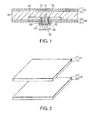
Fig. 1 is a sectional view of an antenna according to a first exemplary embodiment of this invention. -
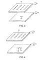
Fig. 2 is an explanatory view illustrating a manufacturing method for the antenna ofFig. 1 . -
Fig. 3 is an explanatory view illustrating the manufacturing method for the antenna ofFig. 1 . -
Fig. 4 is an explanatory view illustrating the manufacturing method for the antenna ofFig. 1 . -
Fig. 5 is an explanatory view illustrating the manufacturing method for the antenna ofFig. 1 . - Now, referring to the drawings, description is given of an exemplary embodiment of this invention.
- Referring to
Fig. 1 , an antenna according to a first exemplary embodiment of this invention includes afirst face plate 10, asecond face plate 20 parallel to thefirst face place 10, and apower supply section 30. Thepower supply section 30 is, for example, a coaxial connector, and includes anapical portion 31 and a flange-like short-circuit section 32. A center conductor protrudes from theapical portion 31. - The
first face plate 10 includes a first thin metal plate 11 on an outer side and afirst dielectric plate 12 on an inner side, while thesecond face plate 20 includes a secondthin metal plate 21 on the outer side and asecond dielectric plate 22 on the inner side. The first thin metal plate 11 and the secondthin metal plate 21 are each made of copper foil. Thefirst dielectric plate 12 and thesecond dielectric plate 22 are each, for example, a composite dielectric plate. - The antenna of the exemplary embodiment further includes a
metal plate 40 serving as a fastening plate on an inner side of thesecond dielectric plate 22. Themetal plate 40 of the figure is a ring-like metal plate (ring-like fastening plate). - The second
thin metal plate 21, thesecond dielectric plate 22, and themetal plate 40 each have, at a center portion thereof, ahole 50 for power supply section with a size allowing insertion of theapical portion 31 of thepower supply section 30 and forbidding insertion of the flange-like short-circuit section 32 of thepower supply section 30. - The flange-like short-
circuit section 32, the second thin metal plate (copper foil) 21, and thesecond dielectric plate 22 each have a plurality of insertion holes 65, through which a plurality ofscrews 60 are inserted. - The metal plate (ring-like metal plate) 40 has a plurality of tapped
holes 70, into which the plurality ofscrews 60 are threadingly inserted. - Under a state in which the
apical portion 31 of thepower supply section 30 is inserted from the outer side of thesecond face plate 20 into thehole 50 for power supply section of the second thin metal plate (copper foil) 21, thesecond dielectric plate 22, and the metal plate (ring-like metal plate) 40, the plurality ofscrews 60 are inserted from the outer side of the flange-like short-circuit section 31 of thepower supply section 30 through the plurality of insertion holes 65 of the flange-like short-circuit section 31, the second thin metal plate (copper foil) 21, and thesecond dielectric plate 22. Then, the plurality ofscrews 60 are threadingly inserted into the plurality of tappedholes 70 of themetal plate 40. Accordingly, thepower supply section 30 is fixed to thesecond face plate 20, and electrical conductivity between the flange-like short-circuit section 31 of thepower supply section 30 and the second thin metal plate (copper foil) 21 is established through direct contact without soldering. - There is provided a
dielectric honeycomb 80 between thefirst dielectric plate 12 and the metal plate (ring-like metal plate) 40, and between thefirst dielectric plate 22 and thesecond dielectric plate 12. - The
first face plate 10 has slots 13 (Fig. 3 ). - The antenna of the exemplary embodiment is an antenna to be mounted on a satellite, and is a radial line slot array antenna with honeycomb structure.
- As described above, the lightweight composite
dielectric plate 22 with thecopper foil 21 is used for the antenna of the exemplary embodiment to obtain a high strength. Further, the ring-like metal plate 40 for fastening thepower supply section 30 is provided on the inner side of the lightweight compositedielectric plate 22 with thecopper foil 21. Thecopper foil 21 has a thickness of a skin depth or more, which is necessary to perform radio frequency (RF) transmission. Because the ring-like metal plate 40 is provided on the inner side of thecomposite dielectric plate 22, the electrical conductivity of the flange-like short-circuit section 31 of thepower supply section 30 with respect to themetal foil plate 21 can be established stably by using thescrews 60 or the like. The electrical conductivity of the flange-like short-circuit section 31 of thepower supply section 30 with respect to themetal foil plate 21 can be established without soldering. - The above-mentioned antenna is manufactured as follows.
- As illustrated in
Fig. 2 , thefirst face plate 10 including the first thin metal plate (copper foil) 11 on the outer side and thefirst dielectric plate 12 on the inner side, and thesecond face plate 20 including the thin metal plate (copper foil) 21 on the outer side and thedielectric plate 22 on the inner side (thesecond face plate 20 of the figure is reversed when used) are prepared. At this time, the thin metal plate (copper foil) 11 and thefirst dielectric plate 12 are integrally formed to obtain thefirst face plate 10, and the thin metal plate (copper foil) 21 and thedielectric plate 22 are integrally formed to obtain thesecond face plate 20. - Subsequently, referring to
Fig. 1 , the metal plate (ring-like metal plate) 40, which is to serve as the fastening plate (ring-like fastening plate) on the inner side of thedielectric plate 22, is prepared. The metal plate (ring-like metal plate) 40 has, at the center portion thereof, thehole 50 for power supply section allowing insertion of theapical portion 31 of thepower supply section 30 and forbidding insertion of the flange-like short-circuit section 32 of thepower supply section 30. Further, the metal plate (ring-like metal plate) 40 has the plurality of tappedholes 70, into which the plurality ofscrews 60 are threadingly inserted. - Subsequently, as illustrated in
Fig. 3 , thefirst face plate 10 is subjected to slot etching to form theslots 13, and thesecond face plate 20 is subjected to etching for power supply section to form thehole 50 for power supply section. Accordingly, the thin metal plate (copper foil) 21 and thedielectric plate 22 each have, at the center portion thereof, thehole 50 for power supply section allowing insertion of theapical portion 31 of thepower supply section 30 and forbidding insertion of the flange-like short-circuit section 32 of thepower supply section 30. - Subsequently, as illustrated in
Fig. 4 , the plurality of insertion holes 65 are formed in thesecond face plate 20 at positions corresponding to the tappedholes 70 of the metal plate (ring-like metal plate) 40 (Fig. 1 ) for fastening thepower supply section 30. Accordingly, the thin metal plate (copper foil) 21 and thedielectric plate 22 each have the plurality of insertion holes 65, through which the plurality ofscrews 60 are inserted. - Subsequently, referring to
Fig. 1 , the plurality of insertion holes 65, through which the plurality ofscrews 60 are inserted, are formed also in the flange-like short-circuit section 32 of thepower supply section 30. - Subsequently, as illustrated in
Fig. 5 , the metal plate (ring-like metal plate) 40 is bonded to the inner side of thedielectric plate 22 of thesecond face plate 20, and a fittedportion 85 of thedielectric honeycomb 80, into which the metal plate (ring-like metal plate) 40 is fitted, is cut out in advance. Note that, illustration of the insertion holes 65 and the tappedholes 70 is omitted inFig. 5 . - Finally, adhesive films (not shown) are sandwiched between the
first face plate 10 and thedielectric honeycomb 80, and between thesecond face plate 20 and thedielectric honeycomb 80, respectively, and after heat and pressure forming, the tappedholes 70 of the metal plate (ring-like metal plate) 40 and the insertion holes 65 of thesecond face plate 20 are used to integrate thepower supply section 30. In this manner, the antenna ofFig. 1 is completed. - In other words, referring to
Figs. 5 and1 , under the state in which theapical portion 31 of thepower supply section 30 is inserted from the outer side of thesecond face plate 20 into thehole 50 for power supply section of the thin metal plate (copper foil) 21, thedielectric plate 22, and the metal plate (ring-like metal plate) 40, the plurality ofscrews 60 are inserted from the outer side of the flange-like short-circuit section 32 of thepower supply section 30 through the plurality of insertion holes 65 of the flange-like short-circuit section 32, the thin metal plate (copper foil) 21, and thedielectric plate 22. Then, the plurality ofscrews 60 are threadingly inserted into the plurality of tappedholes 70 of the thin metal plate (copper foil) 21. Accordingly, the electrical conductivity between the flange-like short-circuit section 32 and the thin metal plate (copper foil) 21 is established through direct contact. - By using the thin metal plates (copper foil), the
first face plate 10 and thesecond face plate 20 which are parallel to each other may be thin, which contributes to reduction in mass. In addition, by fastening thepower supply section 30 directly to thesecond face plate 20 with the screws, electrical connection between the flange-like short-circuit section 32 of thepower supply section 30 and the thin metal plate (copper foil) 21 of thesecond face plate 20 can be established. Thus, there can be obtained structure which has no excessive thermal stress applied to a test sample at the time of manufacturing and has high resistance to the heat cycle. - Aspects of the exemplary embodiment of this invention are described below.
- (1) An antenna includes:
- a first face plate;
- a second face plate parallel to the first face plate; and
- a power supply section including:
- an apical portion; and
- a flange-like short-circuit section,
- in which the first face plate includes:
- a first thin metal plate on an outer side; and
- a first dielectric plate on an inner side,
- in which the second face plate includes:
- a second thin metal plate on the outer side; and
- a second dielectric plate on the inner side,
- in which the antenna further includes a fastening plate on the inner side of the second dielectric plate,
- in which the second thin metal plate, the second dielectric plate, and the fastening plate each include, at a center portion thereof, a hole for the power supply section allowing insertion of the apical portion and forbidding insertion of the flange-like short-circuit section,
- in which the flange-like short-circuit section, the second thin metal plate, and the second dielectric plate each include a plurality of insertion holes, through which a plurality of screws are inserted,
- in which the fastening plate includes a plurality of tapped holes, into which the plurality of screws are threadingly inserted, and
- in which, under a state in which the apical portion is inserted from the outer side of the second face plate into the hole for the power supply section of the second thin metal plate, the second dielectric plate, and the fastening plate, the plurality of screws are inserted from the outer side of the flange-like short-circuit section through the plurality of insertion holes of the flange-like short-circuit section, the second thin metal plate, and the second dielectric plate, and the plurality of screws are threadingly inserted into the plurality of tapped holes of the fastening plate so that electrical conductivity between the flange-like short-circuit section and the second thin metal plate is established through direct contact.
- (2) In the antenna described in the above item (1), under the state in which the apical portion is inserted from the outer side of the second face plate into the hole for the power supply section of the second thin metal plate, the second dielectric plate, and the fastening plate, the plurality of screws are inserted from the outer side of the flange-like short-circuit section through the plurality of insertion holes of the flange-like short-circuit section, the second thin metal plate, and the second dielectric plate, and the plurality of screws are threadingly inserted into the plurality of tapped holes of the fastening plate so that the electrical conductivity between the flange-like short-circuit section and the second thin metal plate is established through the direct contact without soldering.
- (3) In the antenna described in the above item (1), under the state in which the apical portion is inserted from the outer side of the second face plate into the hole for the power supply section of the second thin metal plate, the second dielectric plate, and the fastening plate, the plurality of screws are inserted from the outer side of the flange-like short-circuit section through the plurality of insertion holes of the flange-like short-circuit section, the second thin metal plate, and the second dielectric plate, and the plurality of screws are threadingly inserted into the plurality of tapped holes of the fastening plate so that the power supply section is fixed to the second face plate, and the electrical conductivity between the flange-like short-circuit section and the second thin metal plate is established through the direct contact without soldering.
- (4) In the antenna described in any one of the above items (1) to (3), the fastening plate includes a ring-like fastening plate having the hole for the power supply section formed at the center portion thereof.
- (5) In the antenna according to claim 4, the antenna further includes a dielectric honeycomb between the first dielectric plate and the ring-like fastening plate, and between the first dielectric plate and the second dielectric plate.
- (6) In the antenna described in any one of the above items (1) to (5), the first thin metal plate and the second thin metal plate are each made of copper foil.
- (7) In the antenna described in any one of the above items (1) to (6), the first face plate includes a slot.
- (8) In the antenna according to any one of claims (1) to (7), in which the antenna includes an antenna to be mounted on a satellite.
- (9) Provided is a manufacturing method for an antenna,
the antenna including:- a first face plate;
- a second face plate parallel to the first face plate; and
- a power supply section including:
- an apical portion; and
- a flange-like short-circuit section,
- the manufacturing method including, when fixing the power supply section to the second face plate:
- preparing, as the second face plate, a face plate including a thin metal plate on an outer side and a dielectric plate on an inner side;
- further preparing a fastening plate on the inner side of the dielectric plate,
the thin metal plate, the dielectric plate, and the fastening plate each including, at a center portion thereof, a hole for the power supply section allowing insertion of the apical portion and forbidding insertion of the flange-like short-circuit section,
the flange-like short-circuit section, the thin metal plate, and the dielectric plate each including a plurality of insertion holes, through which a plurality of screws are inserted,
the fastening plate including a plurality of tapped holes, into which the plurality of screws are threadingly inserted; and - under a state in which the apical portion is inserted from the outer side of the second face plate into the hole for the power supply section of the thin metal plate, the dielectric plate, and the fastening plate, inserting the plurality of screws from the outer side of the flange-like short-circuit section through the plurality of insertion holes of the flange-like short-circuit section, the thin metal plate, and the dielectric plate, and threadingly inserting the plurality of screws into the plurality of tapped holes of the fastening plate so that electrical conductivity between the flange-like short-circuit section and the thin metal plate is established through direct contact.
- (10) In the manufacturing method for an antenna described in the above item (9), under the state in which the apical portion is inserted from the outer side of the second face plate into the hole for the power supply section of the thin metal plate, the dielectric plate, and the fastening plate, the plurality of screws are inserted from the outer side of the flange-line short-circuit section through the plurality of insertion holes of the flange-like short-circuit section, the thin metal plate, and the dielectric plate, and the plurality of screws are threadingly inserted into the plurality of tapped holes of the fastening plate so that the electrical conductivity between the flange-like short-circuit section and the thin metal plate is established through the direct contact without soldering.
- (11) In the manufacturing method for an antenna described in the above item (9) or (10), the fastening plate includes a ring-like fastening plate having the hole for the power supply section formed at the center portion thereof.
- (12) In the manufacturing method for an antenna described in any one of the above items (9) to (11), the thin metal plate is made of copper foil.
- (13) In the manufacturing method for an antenna described in any one of the above items (9) to (12), in which the antenna includes an antenna to be mounted on a satellite.
- While the invention has been particularly shown and described with reference to the exemplary embodiment thereof, the invention is not limited to the exemplary embodiment. It will be understood by those of ordinary skill in the art that various changes in form and details may be made therein without departing from the spirit and scope of the present invention as defined by the claims. For example, in the description of the above-mentioned exemplary embodiment, the metal plate (or ring-like metal plate) 40 is taken as an example of the fastening plate (or ring-like fastening plate), but alternatively, the fastening plate (or ring-like fastening plate) may be made of another material than metal as long as the use of the material allows fastening with the plurality of screws.
- This application is based upon and claims the benefit of priority from Japanese Patent Application No.
2008-319714, filed on December 16, 2008
Claims (13)
- An antenna, comprising:a first face plate;a second face plate parallel to the first face plate; anda power supply section comprising:an apical portion; anda flange-like short-circuit section,wherein the first face plate comprises:a first thin metal plate on an outer side; anda first dielectric plate on an inner side,wherein the second face plate comprises:a second thin metal plate on the outer side; anda second dielectric plate on the inner side,wherein the antenna further comprises a fastening plate on the inner side of the second dielectric plate,wherein the second thin metal plate, the second dielectric plate, and the fastening plate each comprise, at a center portion thereof, a hole for the power supply section allowing insertion of the apical portion and forbidding insertion of the flange-like short-circuit section,wherein the flange-like short-circuit section, the second thin metal plate, and the second dielectric plate each comprise a plurality of insertion holes, through which a plurality of screws are inserted,wherein the fastening plate comprises a plurality of tapped holes, into which the plurality of screws are threadingly inserted, andwherein, under a state in which the apical portion is inserted from the outer side of the second face plate into the hole for the power supply section of the second thin metal plate, the second dielectric plate, and the fastening plate, the plurality of screws are inserted from the outer side of the flange-like short-circuit section through the plurality of insertion holes of the flange-like short-circuit section, the second thin metal plate, and the second dielectric plate, and the plurality of screws are threadingly inserted into the plurality of tapped holes of the fastening plate so that electrical conductivity between the flange-like short-circuit section and the second thin metal plate is established through direct contact.
- An antenna according to claim 1, wherein, under the state in which the apical portion is inserted from the outer side of the second face plate into the hole for the power supply section of the second thin metal plate, the second dielectric plate, and the fastening plate, the plurality of screws are inserted from the outer side of the flange-like short-circuit section through the plurality or insertion holes of the flange-like short-circuit section, the second thin metal plate, and the second dielectric plate, and the plurality of screws are threadingly inserted into the plurality of tapped holes of the fastening plate so that the "electrical conductivity between the flange-like short-circuit section and the second thin metal plate is established through the direct contact without soldering.
- An antenna according to claim 1, wherein, under the state in which the apical portion is inserted from the outer side of the second face plate into the hole for the power supply section of the second thin metal plate, the second dielectric plate, and the fastening plate, the plurality of screws are inserted from the outer side of the flange-like short-circuit section through the plurality of insertion holes of the flange-like short-circuit section, the second thin metal plate, and the second dielectric plate, and the plurality of screws are threadingly inserted into the plurality of tapped holes of the fastening plate so that the power supply section is fixed to the second face plate, and the electrical conductivity between the flange-like short-circuit section and the second thin metal plate is established through the direct contact without soldering.
- An antenna according to any one of claims 1 to 3, wherein the fastening plate comprises a ring-like fastening plate having the hole for the power supply section formed at the center portion thereof.
- An antenna according to claim 4, further comprising a dielectric honeycomb between the first dielectric plate and the ring-like fastening plate, and between the first dielectric plate and the second dielectric plate.
- An antenna according to any one of claims 1 to 5, wherein the first thin metal plate and the second thin metal plate are each made of copper foil.
- An antenna according to any one of claims 1 to 6, wherein the first face plate comprises a slot.
- An antenna according to any one of claims 1 to 7, wherein the antenna comprises an antenna to be mounted on a satellite.
- A manufacturing method for an antenna,
the antenna, comprising:a first face plate;a second face plate parallel to the first face plate; anda power supply section comprising:an apical portion; anda flange-like short-circuit section,the manufacturing method comprising, when fixing the power supply section to the second face plate:preparing, as the second face plate, a face plate comprising a thin metal plate on an outer side and a dielectric plate on an inner side;further preparing a fastening plate on the inner side of the dielectric plate,
the thin metal plate, the dielectric plate, and the fastening plate each comprising, at a center portion thereof, a hole for the power supply section allowing insertion of the apical portion and forbidding insertion of the flange-like short-circuit section,
the flange-like short-circuit section, the thin metal plate, and the dielectric plate each comprising a plurality of insertion holes, through which a plurality of screws are inserted,
the fastening plate comprising a plurality of tapped holes, into which the plurality of screws are threadingly inserted; andunder a state in which the apical portion is inserted from the outer side of the second face plate into the hole for the power supply section of the thin metal plate, the dielectric plate, and the fastening plate, inserting the plurality of screws from the outer side of the flange-like short-circuit section through the plurality of insertion holes of the flange-like short-circuit section, the thin metal plate, and the dielectric plate, and threadingly inserting the plurality of screws into the plurality of tapped holes of the fastening plate so that electrical conductivity between the flange-like short-circuit section and the thin metal plate is established through direct contact. - A manufacturing method for an antenna according to claim 9, wherein, under the state in which the apical portion is inserted from the outer side of the second face plate into the hole for the power supply section of the thin metal plate, the dielectric plate, and the fastening plate, the plurality of screws are inserted from the outer side of the flange-like short-circuit section through the plurality of insertion holes of the flange-like short-circuit section, the thin metal plate, and the dielectric plate, and the plurality of screws are threadingly inserted into the plurality of tapped holes of the fastening plate so that the electrical conductivity between the flange-like short-circuit section and the thin metal plate is established through the direct contact without soldering.
- A manufacturing method for an antenna according to claim 9 or 10, wherein the fastening plate comprises a ring-like fastening plate having the hole for the power supply section formed at the center portion thereof.
- A manufacturing method for an antenna according to any one of claims 9 to 11, wherein the thin metal plate is made of copper foil.
- A manufacturing method for an antenna according to any one of claims 9 to 12, wherein the antenna comprises an antenna to be mounted on a satellite.
Applications Claiming Priority (2)
| Application Number | Priority Date | Filing Date | Title |
|---|---|---|---|
| JP2008319714A JP2010147561A (en) | 2008-12-16 | 2008-12-16 | Antenna and manufacturing method thereof |
| PCT/JP2009/071010 WO2010071163A1 (en) | 2008-12-16 | 2009-12-10 | Antenna and manufacturing method therefor |
Publications (2)
| Publication Number | Publication Date |
|---|---|
| EP2378608A1 true EP2378608A1 (en) | 2011-10-19 |
| EP2378608A4 EP2378608A4 (en) | 2015-07-08 |
Family
ID=42268833
Family Applications (1)
| Application Number | Title | Priority Date | Filing Date |
|---|---|---|---|
| EP09833466.7A Withdrawn EP2378608A4 (en) | 2008-12-16 | 2009-12-10 | ANTENNA AND METHOD FOR MANUFACTURING THE SAME |
Country Status (5)
| Country | Link |
|---|---|
| US (1) | US20110241955A1 (en) |
| EP (1) | EP2378608A4 (en) |
| JP (1) | JP2010147561A (en) |
| CN (1) | CN102257670B (en) |
| WO (1) | WO2010071163A1 (en) |
Family Cites Families (11)
| Publication number | Priority date | Publication date | Assignee | Title |
|---|---|---|---|---|
| JPH0828606B2 (en) | 1986-07-29 | 1996-03-21 | ソニー株式会社 | Antenna feeding mechanism |
| US5276455A (en) * | 1991-05-24 | 1994-01-04 | The Boeing Company | Packaging architecture for phased arrays |
| NL9301677A (en) * | 1993-09-29 | 1995-04-18 | Hollandse Signaalapparaten Bv | Multipatch antenna. |
| JPH08236220A (en) * | 1995-02-27 | 1996-09-13 | Nec Eng Ltd | Fitting clip |
| US5706019A (en) * | 1996-06-19 | 1998-01-06 | Motorola, Inc. | Integral antenna assembly for a radio and method of manufacturing |
| CN100419925C (en) * | 1997-11-18 | 2008-09-17 | 松下电器产业株式会社 | Laminates and Capacitors |
| JP2000091045A (en) * | 1998-09-11 | 2000-03-31 | Kyocera Corp | Coaxial connector mounting structure |
| JP2001345634A (en) | 2000-05-31 | 2001-12-14 | Hitachi Cable Ltd | Array antenna |
| JP3858581B2 (en) * | 2000-09-26 | 2006-12-13 | セイコーエプソン株式会社 | Liquid crystal device and electronic device |
| CN2786908Y (en) * | 2004-09-30 | 2006-06-07 | 南京理工大学 | Coaxial incited invisible plasma antenna |
| JP4479606B2 (en) * | 2005-06-28 | 2010-06-09 | Tdk株式会社 | Antenna device |
-
2008
- 2008-12-16 JP JP2008319714A patent/JP2010147561A/en active Pending
-
2009
- 2009-12-10 WO PCT/JP2009/071010 patent/WO2010071163A1/en not_active Ceased
- 2009-12-10 US US13/139,469 patent/US20110241955A1/en not_active Abandoned
- 2009-12-10 CN CN200980150843.7A patent/CN102257670B/en not_active Expired - Fee Related
- 2009-12-10 EP EP09833466.7A patent/EP2378608A4/en not_active Withdrawn
Non-Patent Citations (1)
| Title |
|---|
| See references of WO2010071163A1 * |
Also Published As
| Publication number | Publication date |
|---|---|
| EP2378608A4 (en) | 2015-07-08 |
| WO2010071163A1 (en) | 2010-06-24 |
| CN102257670B (en) | 2014-09-10 |
| JP2010147561A (en) | 2010-07-01 |
| CN102257670A (en) | 2011-11-23 |
| US20110241955A1 (en) | 2011-10-06 |
Similar Documents
| Publication | Publication Date | Title |
|---|---|---|
| US8378705B2 (en) | Wiring substrate and probe card | |
| KR101409343B1 (en) | Circuit board manufacturing method and circuit board | |
| EP2428971B1 (en) | Three-dimensional liquid crystal polymer multilayer circuit board including membrane switch and related methods | |
| EP3239115A1 (en) | Heat transport structure and manufacturing method therefor | |
| EP2081245A1 (en) | Three-dimensional liquid crystal polymer multilayer circuit board including battery and related methods | |
| WO2013003453A2 (en) | Insert for radomes and methods of manufacturing insert for radomes | |
| EP2081418A2 (en) | Method for making three-dimensional liquid crystal polymer multilayer circuit boards | |
| US20200335860A1 (en) | Antenna | |
| US9691964B2 (en) | Piezoelectric element unit and driving device | |
| US7607223B2 (en) | Electro-fluidic interconnect attachment | |
| US20110241955A1 (en) | Antenna and manufacturing method therefor | |
| CN111649767B (en) | A split piezoelectric sensor | |
| US4983237A (en) | Antenna lamination technique | |
| CN108260279B (en) | Manufacturing method of battery FPC and battery FPC | |
| US9992892B2 (en) | Connecting device for connecting electrical lines to electrical contacts | |
| CN213845750U (en) | Millimeter wave radio frequency coaxial connector | |
| EP3798137A1 (en) | Pipe structure and truss structure, and artificial satellite using such structures | |
| EP4495452A1 (en) | Disc spring member | |
| JPH11354219A (en) | Coaxial connector | |
| JP2011103578A (en) | Planar antenna | |
| CN222966176U (en) | Cells, Batteries, Electronic Devices and Vehicles | |
| CN222558839U (en) | Fan device and electronic equipment | |
| EP4356476B1 (en) | Metal-diamond composite-based radio frequency waveguide housing | |
| JP5906738B2 (en) | Fastening structure and manufacturing method of fastening parts | |
| CN112672501B (en) | Processing method of columnar printed circuit board, printed circuit board and electronic equipment |
Legal Events
| Date | Code | Title | Description |
|---|---|---|---|
| PUAI | Public reference made under article 153(3) epc to a published international application that has entered the european phase |
Free format text: ORIGINAL CODE: 0009012 |
|
| 17P | Request for examination filed |
Effective date: 20110715 |
|
| AK | Designated contracting states |
Kind code of ref document: A1 Designated state(s): AT BE BG CH CY CZ DE DK EE ES FI FR GB GR HR HU IE IS IT LI LT LU LV MC MK MT NL NO PL PT RO SE SI SK SM TR |
|
| DAX | Request for extension of the european patent (deleted) | ||
| RA4 | Supplementary search report drawn up and despatched (corrected) |
Effective date: 20150610 |
|
| RIC1 | Information provided on ipc code assigned before grant |
Ipc: H01Q 1/28 20060101ALI20150604BHEP Ipc: H01Q 1/38 20060101AFI20150604BHEP Ipc: H01Q 21/06 20060101ALI20150604BHEP |
|
| RAP1 | Party data changed (applicant data changed or rights of an application transferred) |
Owner name: THE JAPAN AEROSPACE EXPLORATION AGENCY Owner name: NEC SPACE TECHNOLOGIES, LTD. |
|
| STAA | Information on the status of an ep patent application or granted ep patent |
Free format text: STATUS: THE APPLICATION HAS BEEN WITHDRAWN |
|
| 18W | Application withdrawn |
Effective date: 20160330 |