EP2378531A1 - Switch unit and circuit breaker for a medium voltage circuit - Google Patents
Switch unit and circuit breaker for a medium voltage circuit Download PDFInfo
- Publication number
- EP2378531A1 EP2378531A1 EP10160116A EP10160116A EP2378531A1 EP 2378531 A1 EP2378531 A1 EP 2378531A1 EP 10160116 A EP10160116 A EP 10160116A EP 10160116 A EP10160116 A EP 10160116A EP 2378531 A1 EP2378531 A1 EP 2378531A1
- Authority
- EP
- European Patent Office
- Prior art keywords
- stack
- switch contact
- switch
- switch unit
- horn
- Prior art date
- Legal status (The legal status is an assumption and is not a legal conclusion. Google has not performed a legal analysis and makes no representation as to the accuracy of the status listed.)
- Granted
Links
Images

Classifications
-
- H—ELECTRICITY
- H01—ELECTRIC ELEMENTS
- H01H—ELECTRIC SWITCHES; RELAYS; SELECTORS; EMERGENCY PROTECTIVE DEVICES
- H01H9/00—Details of switching devices, not covered by groups H01H1/00 - H01H7/00
- H01H9/30—Means for extinguishing or preventing arc between current-carrying parts
- H01H9/34—Stationary parts for restricting or subdividing the arc, e.g. barrier plate
- H01H9/36—Metal parts
-
- H—ELECTRICITY
- H01—ELECTRIC ELEMENTS
- H01H—ELECTRIC SWITCHES; RELAYS; SELECTORS; EMERGENCY PROTECTIVE DEVICES
- H01H33/00—High-tension or heavy-current switches with arc-extinguishing or arc-preventing means
- H01H33/02—Details
- H01H33/04—Means for extinguishing or preventing arc between current-carrying parts
- H01H33/08—Stationary parts for restricting or subdividing the arc, e.g. barrier plate
- H01H33/10—Metal parts
Definitions
- the present invention relates to a switch unit for a medium voltage circuit breaker including a first switch contact; a second switch contact, wherein the first switch contact moves between a first position in which the first switch contact contacts the second switch contact and a second position in which the first and second switch contacts are separated from each other; a positioning element to position an arc chute on the switch unit, wherein the arc chute includes at least two stacks of a plurality of substantially parallel metal plates, wherein each stack has a proximal end adapted to be disposed in the direction of the switch unit.
- the present disclosure relates to a circuit breaker.
- circuit breakers or air circuit breakers are used in a direct current (DC) circuit on railway vehicles.
- DC direct current
- high speed DC circuit breakers may switch direct currents with more than 500 Volt and 5000 Ampere.
- an adaptable arc-chute for circuit breaker including a plurality of arc chute units connected in series and is characterized by further including a switch which is connected in parallel with a part of the arc-chute units to bypass said part of the arc chute units when in a closed position.
- the horns which are connected to the switch contacts, are heavily used.
- the horns are used to guide an arc into an arc chute, however the feet of the arcs remain on the horns during the arcing time.
- the arc heats up the horns, which immediately start to evaporate and generate gas.
- the horns wear-out and must be changed after a certain number of operations.
- the horns have to be exchanged regularly before the end of the lifetime of the circuit breaker.
- the horns are difficult to exchange.
- a lot of gases are generated because of the heat concentration, typically most of the gases are concentrated in a limited volume, close to the switch contacts. These gases may generate plasma and a re-ignition may occur.
- Object of the invention is to provide a switch unit and a circuit breaker for a medium voltage circuit that does not present the drawbacks of the prior art, in particular to provide low usage of the horns and a longer lifetime of the switch unit.
- a switch unit for a DC medium voltage circuit breaker including a first switch contact; a second switch contact, wherein the first switch contact is movable between a first position in which the first switch contact contacts the second switch contact and a second position in which the first and second switch contacts are separated from each other; a positioning element to position an arc chute on the switch unit, wherein the arc chute includes at least two stacks of a plurality of substantially parallel metal plates; a first connection device adapted and/or capable to electrically connect the first switch contact to a predetermined metal plate selected of the most proximal 25% metal plates of the first stack and; a second connection device adapted and/or capable to electrically connect the second switch contact to a predetermined metal plate selected of the most proximal 25% metal plates of the second stack.
- each stack has a proximal end which is adapted and/or capable to be disposed towards of the switch unit.
- the circuit breaker is an air DC circuit breaker.
- each current interruption generates an arc.
- an arc starts from a contact separation and remains until the current is zero.
- high speed DC circuit breakers build up DC voltages that are higher than the net voltage.
- air circuit breakers may use an arc chute or extinguish chamber in which metallic plates are used to split arcs into several partial arcs, the arc is lengthened and gases are used to increase the arc voltage by a chemical effect, for example by evaporation of plastic or another material.
- a circuit breaker which has horns having a longer lifetime.
- the predetermined metal plates of the first stack and the second stack have the same potential as the respective first and second switch contacts.
- the level 0 metal plates or the predetermined metal plates of the arc chute are connected with equipotential connections, for example electrical connections, to the switch contacts.
- the arc feet Once the arc feet have jumped on the level 0 or the predetermined metal plates of the respective stacks, the current flows through the equipotential connection.
- the switch contacts and the horns are cooler than in prior circuit breakers because the arcs, in particular the arc feet, are faster transferred from the horns to the predetermined metal plates or to the level 0 of the arc chute. Further, the arc feet have a bigger distance from each other.
- the arc chute is more easy and faster to exchange than the horns, so that a longer lifetime of the horns would lead to a shorter maintenance of the arc chute. This may be important in case the arc chute is used on a vehicle, for example a train.
- the lifetime of the horns is about the same as the lifetime of the switch contacts and the driving unit for moving the switch contact of the circuit breaker. Thus, during maintenance, only the arc chute may be exchanged if they are used.
- the predetermined metal plate of the first stack is selected of the most proximal 20%, in particular the most proximal 10%, metal plates of the first stack.
- the predetermined metal plate of the second stack is selected of the most proximal 20%, in particular the most proximal 10%, metal plates of the second stack.
- the first connection device and/or the second connection device are disposed such that the arc feet of an arc created between the first switch contact and the second switch contact in an interruption operation are transferred to the predetermined metal plates of the first stack and the second stack.
- the positioning element is a screw, a hinge, a bolt, a stop, a bar, and the like.
- the positioning element is used for connecting the arc chute to the switching unit.
- the second switch contact moves substantially along a moving direction.
- the switch unit further includes a first horn, in particular manufactured of steel or iron, electrically connected to the first switch contact, wherein the first switch contact is adapted to guide a first foot of an electric arc to the arc chute, in particular to the first stack of the arc chute, and a second horn, in particular manufactured of steel or iron, electrically connected to the second switch contact adapted to guide a second foot of the electric arc to the arc chute, in particular to the second stack of the arc chute.
- a first horn in particular manufactured of steel or iron
- the first horn and/or the second horn have a fixed first end in the direction of the first/or second switch contact, and a resilient second end opposite to their respective first end, wherein in particular the second end is movable in direction of the arc chute to be mounted on the switch unit.
- the first connection device is disposed on the first horn, and/or the second connection device is disposed on the second horn, wherein in particular the first connection device is disposed at the second end of the first horn and/or the second connection device is disposed at the second end of the second horn.
- first connection device and/or the second connection device is/are respectively a graphite conductor, in particular fixed to the respective first or second horn,.
- the second end of the first horn and/or the second end of the second horn is biased in direction of the stacks of the arc chute adapted to be mounted on the switch unit.
- the first connection device is a first metallic connector, in particular a bar
- the second connection device is a second metallic connector, in particular a metallic wire.
- the predetermined metal plate of the first stack and/or the predetermined metal plate of the second stack is/are the most proximal metal plate of the respective stack in the direction of the switch unit.
- the first stack and the second stack have respectively a distal end, in particular opposite to the proximal end, wherein a metal plate at the distal end, in particular the most distal metal plate, of the first stack is electrically connected to a metal plate at the distal end, in particular the most distal metal plate, of the second stack.
- a metal plate selected of the most distal 25%, in particular 10%, metal plates of the first stack is electrically connected to a metal plate selected of the most distal 25%, in particular 10%, metal plates of the second stack, in particular by a metal bar.
- the switch unit according to an embodiment disclosed herein is provided for a DC current having more than 600A.
- the present disclosure concerns a circuit breaker for a medium voltage circuit including a switch unit according to an embodiment disclosed herein; and an arc chute.
- the metal plates of each stack of the arc chute are substantially equal.
- the stacks are substantially orthogonal to the moving direction of the first and/or second switch contact.
- the predetermined metal plate of the first stack and/or the predetermined metal plate of the second stack has/have a copper coating.
- the metal plates of the first stack and/or the second stack are manufactured from steel.
- the circuit breaker is a circuit breaker for a traction vehicle, in particular a railway vehicle, a tramway, a trolleybus and the like.
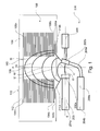
- Fig. 1 shows a side view of a medium voltage direct current (DC) circuit breaker.
- the circuit breaker is typically an air circuit breaker working at medium voltages, typically between 500V and 3600V.
- the circuit breaker includes an arc chute 100 and a switch unit 200.
- the arc chute includes a first stack 102 of metal plates 104a, 104b, ..., 104n and a second stack 106 of metal plates 108a, 108b, ..., 108n.
- the metal plates 104a, 104b, ..., 104n, 108a, 108b, ..., 108n of the first and the second stack 102, 106 are substantially equal.
- An arc space 109 is disposed between the first stack 102 and the second stack 106 of metal plates. Typically, when the circuit breaker is opened, an arc mounts in the arc space 109.
- the arc chute is symmetric to an axis traversing the arc space 109 which is parallel to the stacking direction of first stack 102 of metal plates and the second stack 106 of metal plates.
- the top level metal plate or most distal metal plate 104n of the first stack 102 is electrically connected to the top level metal plate or most distal metal plate 108n of the second stack 106 with a connection bar 110.
- the top level metal plate 104n of the first stack is on the same electrical potential as the top level metal plate 108n of the second stack 106.
- the lowest metal plate or level zero metal plate 104a of the first stack 102 and the lowest metal plate or level zero metal plate 108a of the second stack 106 are typically the closest metal plates of the respective stacks 102, 106 with respect to the switch unit 200.
- the lowest metal plates or most proximal metal plates 104a, 108a and the top level plates 104n, 108n are disposed on opposite ends in stacking direction of the respective stack 102, 106 of metal plates.
- each stack 102, 106 includes about 36 metal plates 104a, 104b, ...104n, 108a, 108b, ...108n.
- Other embodiments may eventually include more than 36 metal plates.
- the number of metal plates typically depends on the arcing voltage respectively the nominal current that is switched by the circuit breaker.
- the arc chute 100 is disposed in a casing having at least one side wall 112.
- the arc chute 100 with its casing may be easily separated from the switch unit 200. Thus, the maintenance time may be reduced.
- the switch unit 200 includes a first switch contact 202a, which may be electrically connected to an electric network or a load by a first switch contact terminal 204a.
- the first switch contact 202a is connected with a first switch contact bar or bus bar 203 to the first switch contact terminal 204a, wherein in particular the first switch contact bar 203 includes the first switch contact terminal 204a.
- the first switch contact 202a is fixed to a first end of the first switch contact bar 203, and the first switch contact terminal 204 is disposed at a second end of the first switch contact bar 203 opposite to the first end.
- the switch unit 200 includes a second switch contact 202b.
- the second switch unit is moved by a driving unit 206 in a moving direction S, to move the second switch contact 202b from a first position in which the first switch contact 202a is in physical contact with the second switch contact 202b and a second position in which the first switch contact 202a is separated from the second switch contact 202b.
- the second position is shown in Fig. 1 .
- the second switch contact 202b may be connected via a second switch contact terminal 204b to an electrical network or the load.
- the second switch contact 202b is electrically connected to the second switch contact terminal 204b by a flexible conductor 208a and a second switch contact bar 208b, wherein the flexible conductor 208a is connected to a first end of the second switch contact bar 208b.
- the second switch contact terminal 204b is disposed at a second end of the second switch contact bar 208b, wherein the second end is opposite to the first end of the second switch contact bar 208b.
- the arc space 109 is disposed above the first and second switch contact in operation of the circuit breaker, when the circuit breaker is in closed position, i.e. the first switch contact 202a contacts the second switch contact 202b.
- the stacking direction of the stack of metal plates 102, 106 is substantially parallel to an arc displacement direction A, which is substantially orthogonal to the moving direction S.
- the stacking direction or arc displacement direction A corresponds to a direction in which the arc extends into the arc chute.
- the metal plates 104a, 104b, ..., 104n, 108a, 108b, ..., 108n and the connection bar 110 is substantially parallel to the moving direction S.
- a first horn 210a is fixed to the first contact 202a to guide a foot of an arc to the metal plates 104a, 104b, ... 104n, in particular to the lowest metal plate 104a, of the first stack 102 of the arc chute 100.
- the switch unit 200 is provided with the second horn 210b which is disposed, such that the arc having foot at the second switch contact 202b jumps to the horn 210b and moves to the metal plates 108a, 108b, ..., 108n, in particular to the lowest metal plate 108a, of the second stack 106.
- the lowest metal plate 104a of the first stack 102 and the lowest metal plate 108a of the second stack 106 are respectively electrically connected to the first switch contact 202a and the second switch contact 202b.
- an arc foot of an arc created by interrupting a current typically do not remain on the first and second horns 210a, 210b and jump on the lowest metal plates 104a, 108a.
- the respective arc foot has jumped to the lowest metal plates, current flows through a respective equipotential connection, which will be explained here-below.
- the horns are not heated up by the arcs and thus do not evaporate.
- the horn wear out is reduced such that the horns, for example the first horn 210a, and a second horn 210b may withstand the life time of the circuit breaker.
- the heat dissipation is increased once the arc has jumped onto the lowest metal plates. Further, less gas is generated close to the switch contacts. Typically, a heat concentration close to the switch contacts is reduced, such that the risk of a plasma generation and recognition phenomenal is reduced.
- Fig. 1 shows a side view of the circuit breaker in the open state, wherein the first switch contact 202a is separated from the second switch contact 202b. Further Fig. 1 shows schematically an arc expansion within the arc chute 200, in particular, the arcs at different moments after the opening of the switch by moving the second switch contact 202b away from the first switch contacts 202a.
- the arc, or one foot of the arc leaves one of the first or second switch contacts 202a, 202b, and jumps to the horn 210a, 210b of the respective switch contact 202a, 202b. This may either happen first on the fixed, i.e. the first switch contact 202a, or on the moving contact, i.e. the second switch contact 202b.
- the arc leaves the second switch contact. Then, the arc feet are located on first horn 210a and the second horn 210b respectively.
- the arc is well established on the lowest metal plates 104a, 108a of the first and second stack 102, 106 respectively and continues to climb within the arc chute, in particular the arc space 109.
- the arc is fully elongated having reached the top of the arc chute, so that the maximum voltage is built.
- the voltage built up by the arc starts at t0, increases from t1 to t4, and reaches its maximum value approximately at t5.
- the sequence is for example influenced by the magnetic field generated by the current, for example for currents greater than 100A, a chimney effect due to hot gases, for example for currents lower than 100A, and/or the mechanical behaviour of the circuit breaker, for example the velocity of the second switch contact 202b.
- the arc remains present until the current is zero, then the arc is naturally extinguished.
- the arcing time is proportional to the prospective short circuit current in time constant of the circuit, the current level when opening, the required voltage to be built up for cutting the contact velocity, for example of the second switch contact, the geometrical circuit breaker design, for example the chimney effect, and/or the material used which has influence on the gas created in the arc chute or the circuit breaker.
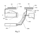
- Fig. 2 shows a portion of a circuit breaker for medium voltage in a perspective view. The same features are designated with the same reference numbers as in Fig. 1 .
- the circuit breaker is shown in Fig. 2 in an open state.
- the lowest metal plate 104a of the first stack 102 is connected via plate connection bar 120 to the first switch contact bar 203, in particular at the second end of the first switch contact.
- the lowest metal plate 104a of the first stack 102 has the same electrical potential as the first switch contact 202a.
- the first metal plate is releasably connected to the plate connection bar 120, and the plate connection bar 120 is releasably connected, for example by a screw, to the first switch contact bar 203.
- the first switch contact 202a may be also electrically connected in another way to the first metal plate 104a of the first stack 102. However, the lowest metal plate, or a metal plate of the first stack 102 close to the first horn 210a is provided to have the same electrical potential as the first horn 210a and/or the first contact switch 202a.
- the second switch contact bar 208b and thus the second switch contact 202b is electrically connected by a first plate connection wire 122a and a second plate connection wire 122b to the lowest metal plate 108a of the second stack 106.
- the lowest metal plate 108a of the second stack 106 has the same electrical potential as the second switch contact 202b.
- the first and the second plate connection wire 122a, 122b are disposed on both sides of the second switch contact 202b, such that the drive unit 206 or a rod of the drive unit 206 is disposed between them.
- the first plate connection wire 122a and the second plate connection wire 122b may be releasably connected to the lowest metal plate 108a of the second stack 106 and/or to the second switch contact bar 208b.
- the second switch contact 202b may be also electrically connected in another way to the first metal plate 108a of the first stack 106.
- the lowest metal plate, or a metal plate of the first stack 106 close to the second horn 210b is provided to have the same electrical potential as the second horn 210b and/or the second contact switch 202b.
- the lowest metal plate 104a of the first stack 102 and/or the lowest metal plate 108a of the second stack 106 may be coated with copper.
- the heat can more easy dissipate on the respective lowest metal plates 104a, 106a and rusting of the first metal plates 104a, 108a is avoided.
- the metal plates of the first stack and the second stack are fabricated of steel.
- the first and second horn 210a, 210b are typically fabricated from steel or iron.
- the equipotential connection between the switch contacts and the respective lowest metal plates has the advantage, that the heat dissipation is improved, when the arc has jumped on the lowest metal plates 104a, 106a. Hence, less gas is generated close to the contact and breaking capability is increased.
- the horns, in particular the first horn 120a, and the second horn 120b should withstand the lifetime of the switch unit 200.
- Fig. 3 shows schematically in a side view a further embodiment of a connection between the respective switch contacts 202a, 202b and the respective lowest metal plates 104a, 108a, which may be combined with other embodiments disclosed herein.
- the same features are designated with the same reference numbers as in the previous drawings.
- the first horn 210a is electrically connected with the first switch contact 202a and the second horn 210b with the second switch contact 202b.
- the first horn 210a has a first end connected to the first switch contact 202a and a second, free end opposite to the first end, in particular in the direction of the moving direction S.
- a first graphite connector 230a is fixed or connected to the second end of the first horn 210a.
- the second horn 210b has a first end in direction of the second switch contact 202b in a second, free end opposite to the first end, in particular in direction of the moving direction S.
- a second graphite connector 230b is fixed or connected to the second end of the second horn 210b.
- the first horn 210a is biased in the direction of the metal plates of the first stack 102 and the second horn 210b is biased in the direction of the metal plates of the second stack 106.
- the lowest metal plates 104a, 104b pushes the respective horns 210a, 210b in the direction of the switch contacts 202a, 202b.
- a reliably electric contact is established between the switch contacts and the respective lowest metal plates 104a, 104b of the arc chute.
Landscapes
- Arc-Extinguishing Devices That Are Switches (AREA)
Abstract
Description
- The present invention relates to a switch unit for a medium voltage circuit breaker including a first switch contact; a second switch contact, wherein the first switch contact moves between a first position in which the first switch contact contacts the second switch contact and a second position in which the first and second switch contacts are separated from each other; a positioning element to position an arc chute on the switch unit, wherein the arc chute includes at least two stacks of a plurality of substantially parallel metal plates, wherein each stack has a proximal end adapted to be disposed in the direction of the switch unit.
- Further the present disclosure relates to a circuit breaker.
- Typically, circuit breakers or air circuit breakers are used in a direct current (DC) circuit on railway vehicles. For example, such high speed DC circuit breakers may switch direct currents with more than 500 Volt and 5000 Ampere.
- From
EP 1 876 618 A1 an adaptable arc-chute for circuit breaker is known including a plurality of arc chute units connected in series and is characterized by further including a switch which is connected in parallel with a part of the arc-chute units to bypass said part of the arc chute units when in a closed position. - In the known circuit breakers the horns, which are connected to the switch contacts, are heavily used. Typically, the horns are used to guide an arc into an arc chute, however the feet of the arcs remain on the horns during the arcing time. For example, the arc heats up the horns, which immediately start to evaporate and generate gas. The horns wear-out and must be changed after a certain number of operations. Thus, the horns have to be exchanged regularly before the end of the lifetime of the circuit breaker. However, the horns are difficult to exchange. Further, a lot of gases are generated because of the heat concentration, typically most of the gases are concentrated in a limited volume, close to the switch contacts. These gases may generate plasma and a re-ignition may occur. Typically, it is complicated to exchange the horns of the circuit breaker.
- Object of the invention is to provide a switch unit and a circuit breaker for a medium voltage circuit that does not present the drawbacks of the prior art, in particular to provide low usage of the horns and a longer lifetime of the switch unit.
- According to an aspect of the disclosure, a switch unit for a DC medium voltage circuit breaker is provided including a first switch contact; a second switch contact, wherein the first switch contact is movable between a first position in which the first switch contact contacts the second switch contact and a second position in which the first and second switch contacts are separated from each other; a positioning element to position an arc chute on the switch unit, wherein the arc chute includes at least two stacks of a plurality of substantially parallel metal plates; a first connection device adapted and/or capable to electrically connect the first switch contact to a predetermined metal plate selected of the most proximal 25% metal plates of the first stack and; a second connection device adapted and/or capable to electrically connect the second switch contact to a predetermined metal plate selected of the most proximal 25% metal plates of the second stack. Typically, each stack has a proximal end which is adapted and/or capable to be disposed towards of the switch unit.
- In a typical embodiment, the circuit breaker is an air DC circuit breaker. Thus, each current interruption generates an arc. Typically, an arc starts from a contact separation and remains until the current is zero. In typical embodiments, to be able to cut out DC currents, high speed DC circuit breakers build up DC voltages that are higher than the net voltage. To build up a DC voltage, air circuit breakers may use an arc chute or extinguish chamber in which metallic plates are used to split arcs into several partial arcs, the arc is lengthened and gases are used to increase the arc voltage by a chemical effect, for example by evaporation of plastic or another material.
- Thus, a circuit breaker is provided which has horns having a longer lifetime. The predetermined metal plates of the first stack and the second stack have the same potential as the respective first and second switch contacts. For example, the level 0 metal plates or the predetermined metal plates of the arc chute are connected with equipotential connections, for example electrical connections, to the switch contacts. Once the arc feet have jumped on the level 0 or the predetermined metal plates of the respective stacks, the current flows through the equipotential connection. Typically, the switch contacts and the horns are cooler than in prior circuit breakers because the arcs, in particular the arc feet, are faster transferred from the horns to the predetermined metal plates or to the level 0 of the arc chute. Further, the arc feet have a bigger distance from each other.
- Further, typically the arc chute is more easy and faster to exchange than the horns, so that a longer lifetime of the horns would lead to a shorter maintenance of the arc chute. This may be important in case the arc chute is used on a vehicle, for example a train. According to an embodiment, the lifetime of the horns is about the same as the lifetime of the switch contacts and the driving unit for moving the switch contact of the circuit breaker. Thus, during maintenance, only the arc chute may be exchanged if they are used.
- In a typical embodiment, the predetermined metal plate of the first stack is selected of the most proximal 20%, in particular the most proximal 10%, metal plates of the first stack.
- In a typical embodiment, the predetermined metal plate of the second stack is selected of the most proximal 20%, in particular the most proximal 10%, metal plates of the second stack.
- In a typical embodiment, which may be combined with other embodiments disclosed herein, the first connection device and/or the second connection device are disposed such that the arc feet of an arc created between the first switch contact and the second switch contact in an interruption operation are transferred to the predetermined metal plates of the first stack and the second stack.
- In a typical embodiment, the positioning element is a screw, a hinge, a bolt, a stop, a bar, and the like. For example, the positioning element is used for connecting the arc chute to the switching unit.
- In a typical embodiment, the second switch contact moves substantially along a moving direction.
- Typically, in an embodiment, the switch unit further includes a first horn, in particular manufactured of steel or iron, electrically connected to the first switch contact, wherein the first switch contact is adapted to guide a first foot of an electric arc to the arc chute, in particular to the first stack of the arc chute, and a second horn, in particular manufactured of steel or iron, electrically connected to the second switch contact adapted to guide a second foot of the electric arc to the arc chute, in particular to the second stack of the arc chute.
- In a typical embodiment, which may be combined with other embodiments disclosed herein, the first horn and/or the second horn have a fixed first end in the direction of the first/or second switch contact, and a resilient second end opposite to their respective first end, wherein in particular the second end is movable in direction of the arc chute to be mounted on the switch unit.
- For example, in an embodiment, the first connection device is disposed on the first horn, and/or the second connection device is disposed on the second horn, wherein in particular the first connection device is disposed at the second end of the first horn and/or the second connection device is disposed at the second end of the second horn.
- In a typical embodiment, which may be combined with other embodiments disclosed herein, the first connection device and/or the second connection device is/are respectively a graphite conductor, in particular fixed to the respective first or second horn,.
- For example, in an embodiment, the second end of the first horn and/or the second end of the second horn is biased in direction of the stacks of the arc chute adapted to be mounted on the switch unit.
- In a typical embodiment, which may be combined with other embodiments disclosed herein, the first connection device is a first metallic connector, in particular a bar, and/or the second connection device is a second metallic connector, in particular a metallic wire.
- For example, in an embodiment, the predetermined metal plate of the first stack and/or the predetermined metal plate of the second stack is/are the most proximal metal plate of the respective stack in the direction of the switch unit.
- In a typical embodiment, the first stack and the second stack have respectively a distal end, in particular opposite to the proximal end, wherein a metal plate at the distal end, in particular the most distal metal plate, of the first stack is electrically connected to a metal plate at the distal end, in particular the most distal metal plate, of the second stack.
- In a typical embodiment, a metal plate selected of the most distal 25%, in particular 10%, metal plates of the first stack is electrically connected to a metal plate selected of the most distal 25%, in particular 10%, metal plates of the second stack, in particular by a metal bar.
- For example, in an embodiment, the switch unit according to an embodiment disclosed herein is provided for a DC current having more than 600A.
- Further, the present disclosure concerns a circuit breaker for a medium voltage circuit including a switch unit according to an embodiment disclosed herein; and an arc chute.
- In a typical embodiment, the metal plates of each stack of the arc chute are substantially equal.
- In a typical embodiment, which may be combined with other embodiments disclosed herein, the stacks are substantially orthogonal to the moving direction of the first and/or second switch contact.
- For example, in an embodiment, the predetermined metal plate of the first stack and/or the predetermined metal plate of the second stack has/have a copper coating.
- In a typical embodiment, the metal plates of the first stack and/or the second stack are manufactured from steel.
- In a typical embodiment, which may be combined with other embodiments disclosed herein, the circuit breaker is a circuit breaker for a traction vehicle, in particular a railway vehicle, a tramway, a trolleybus and the like.
- So that the manner in which the above recited features of the present invention can be understood in detail, a particular description of the invention, brief summarized above, may be discussed with reference to embodiments. The accompanying drawings relate to embodiments of the invention and are described in the following:
-
Fig. 1 shows schematically a side view of an embodiment of a circuit breaker with open switch contacts; -
Fig. 2 shows schematically a side view of a portion of switch unit of a circuit breaker; and -
Fig. 3 shows schematically a side view of a further embodiment of a switch unit. - Reference will now be made in detail to the various embodiments, one or more examples of which are illustrated in the figures. Each example is provided by way of explanation, and is not meant as a limitation of the invention. Within the following description of the drawings, the same reference numbers refer to the same components. Generally, only the differences with respect to individual embodiments are described.
-
Fig. 1 shows a side view of a medium voltage direct current (DC) circuit breaker. The circuit breaker is typically an air circuit breaker working at medium voltages, typically between 500V and 3600V. The circuit breaker includes anarc chute 100 and aswitch unit 200. The arc chute includes afirst stack 102 ofmetal plates second stack 106 ofmetal plates - In a typical embodiment, the
metal plates second stack arc space 109 is disposed between thefirst stack 102 and thesecond stack 106 of metal plates. Typically, when the circuit breaker is opened, an arc mounts in thearc space 109. - Typically, the arc chute is symmetric to an axis traversing the
arc space 109 which is parallel to the stacking direction offirst stack 102 of metal plates and thesecond stack 106 of metal plates. Further, in a typical embodiment, the top level metal plate or mostdistal metal plate 104n of thefirst stack 102 is electrically connected to the top level metal plate or mostdistal metal plate 108n of thesecond stack 106 with aconnection bar 110. Thus, the toplevel metal plate 104n of the first stack is on the same electrical potential as the toplevel metal plate 108n of thesecond stack 106. - The lowest metal plate or level zero
metal plate 104a of thefirst stack 102 and the lowest metal plate or level zerometal plate 108a of thesecond stack 106 are typically the closest metal plates of therespective stacks switch unit 200. Hence, the lowest metal plates or mostproximal metal plates top level plates respective stack - In a typical embodiment, each
stack metal plates - In a typical embodiment, the
arc chute 100 is disposed in a casing having at least oneside wall 112. In a typical embodiment, thearc chute 100 with its casing may be easily separated from theswitch unit 200. Thus, the maintenance time may be reduced. - The
switch unit 200 includes afirst switch contact 202a, which may be electrically connected to an electric network or a load by a firstswitch contact terminal 204a. Typically, thefirst switch contact 202a is connected with a first switch contact bar orbus bar 203 to the firstswitch contact terminal 204a, wherein in particular the firstswitch contact bar 203 includes the firstswitch contact terminal 204a. Typically, thefirst switch contact 202a is fixed to a first end of the firstswitch contact bar 203, and the first switch contact terminal 204 is disposed at a second end of the firstswitch contact bar 203 opposite to the first end. - Further, the
switch unit 200 includes asecond switch contact 202b. The second switch unit is moved by adriving unit 206 in a moving direction S, to move thesecond switch contact 202b from a first position in which thefirst switch contact 202a is in physical contact with thesecond switch contact 202b and a second position in which thefirst switch contact 202a is separated from thesecond switch contact 202b. The second position is shown inFig. 1 . Thesecond switch contact 202b may be connected via a secondswitch contact terminal 204b to an electrical network or the load. Thesecond switch contact 202b is electrically connected to the secondswitch contact terminal 204b by aflexible conductor 208a and a secondswitch contact bar 208b, wherein theflexible conductor 208a is connected to a first end of the secondswitch contact bar 208b. Typically, the secondswitch contact terminal 204b is disposed at a second end of the secondswitch contact bar 208b, wherein the second end is opposite to the first end of the secondswitch contact bar 208b. - Typically, the
arc space 109 is disposed above the first and second switch contact in operation of the circuit breaker, when the circuit breaker is in closed position, i.e. thefirst switch contact 202a contacts thesecond switch contact 202b. Further, the stacking direction of the stack ofmetal plates metal plates connection bar 110 is substantially parallel to the moving direction S. - A
first horn 210a is fixed to thefirst contact 202a to guide a foot of an arc to themetal plates lowest metal plate 104a, of thefirst stack 102 of thearc chute 100. Further, theswitch unit 200 is provided with thesecond horn 210b which is disposed, such that the arc having foot at thesecond switch contact 202b jumps to thehorn 210b and moves to themetal plates lowest metal plate 108a, of thesecond stack 106. - In a typical embodiment, the
lowest metal plate 104a of thefirst stack 102 and thelowest metal plate 108a of thesecond stack 106 are respectively electrically connected to thefirst switch contact 202a and thesecond switch contact 202b. Thus, an arc foot of an arc created by interrupting a current typically do not remain on the first andsecond horns lowest metal plates first horn 210a, and asecond horn 210b may withstand the life time of the circuit breaker. Typically, the heat dissipation is increased once the arc has jumped onto the lowest metal plates. Further, less gas is generated close to the switch contacts. Typically, a heat concentration close to the switch contacts is reduced, such that the risk of a plasma generation and recognition phenomenal is reduced. -
Fig. 1 shows a side view of the circuit breaker in the open state, wherein thefirst switch contact 202a is separated from thesecond switch contact 202b. FurtherFig. 1 shows schematically an arc expansion within thearc chute 200, in particular, the arcs at different moments after the opening of the switch by moving thesecond switch contact 202b away from thefirst switch contacts 202a. - At a first time, t0, after the contact separation of the
first switch contact 202a and thesecond switch contact 202b the arcing starts. - Then, at t1, the arc, or one foot of the arc, leaves one of the first or
second switch contacts horn respective switch contact first switch contact 202a, or on the moving contact, i.e. thesecond switch contact 202b. At t2, the arc leaves the second switch contact. Then, the arc feet are located onfirst horn 210a and thesecond horn 210b respectively. - Then, at t3 the arc feet jump on the respective level zero or
lowest metal plates second stack 102, 104. - At t4 the arc is well established on the
lowest metal plates second stack arc space 109. Finally, at t5 the arc is fully elongated having reached the top of the arc chute, so that the maximum voltage is built. The voltage built up by the arc starts at t0, increases from t1 to t4, and reaches its maximum value approximately at t5. Typically, the sequence is for example influenced by the magnetic field generated by the current, for example for currents greater than 100A, a chimney effect due to hot gases, for example for currents lower than 100A, and/or the mechanical behaviour of the circuit breaker, for example the velocity of thesecond switch contact 202b. - In a typical embodiment, the arc remains present until the current is zero, then the arc is naturally extinguished. Typically, the arcing time is proportional to the prospective short circuit current in time constant of the circuit, the current level when opening, the required voltage to be built up for cutting the contact velocity, for example of the second switch contact, the geometrical circuit breaker design, for example the chimney effect, and/or the material used which has influence on the gas created in the arc chute or the circuit breaker.
-
Fig. 2 shows a portion of a circuit breaker for medium voltage in a perspective view. The same features are designated with the same reference numbers as inFig. 1 . The circuit breaker is shown inFig. 2 in an open state. Further, thelowest metal plate 104a of thefirst stack 102 is connected viaplate connection bar 120 to the firstswitch contact bar 203, in particular at the second end of the first switch contact. Thus, thelowest metal plate 104a of thefirst stack 102 has the same electrical potential as thefirst switch contact 202a. Typically, the first metal plate is releasably connected to theplate connection bar 120, and theplate connection bar 120 is releasably connected, for example by a screw, to the firstswitch contact bar 203. Thefirst switch contact 202a may be also electrically connected in another way to thefirst metal plate 104a of thefirst stack 102. However, the lowest metal plate, or a metal plate of thefirst stack 102 close to thefirst horn 210a is provided to have the same electrical potential as thefirst horn 210a and/or thefirst contact switch 202a. - Further, the second
switch contact bar 208b and thus thesecond switch contact 202b is electrically connected by a firstplate connection wire 122a and a secondplate connection wire 122b to thelowest metal plate 108a of thesecond stack 106. Thus, thelowest metal plate 108a of thesecond stack 106 has the same electrical potential as thesecond switch contact 202b. In a typical embodiment, the first and the secondplate connection wire second switch contact 202b, such that thedrive unit 206 or a rod of thedrive unit 206 is disposed between them. In a typical embodiment, the firstplate connection wire 122a and the secondplate connection wire 122b may be releasably connected to thelowest metal plate 108a of thesecond stack 106 and/or to the secondswitch contact bar 208b. Thesecond switch contact 202b may be also electrically connected in another way to thefirst metal plate 108a of thefirst stack 106. However, the lowest metal plate, or a metal plate of thefirst stack 106 close to thesecond horn 210b is provided to have the same electrical potential as thesecond horn 210b and/or thesecond contact switch 202b. - In a typical embodiment, the
lowest metal plate 104a of thefirst stack 102 and/or thelowest metal plate 108a of thesecond stack 106 may be coated with copper. Thus, the heat can more easy dissipate on the respectivelowest metal plates 104a, 106a and rusting of thefirst metal plates second horn - Typically, the equipotential connection between the switch contacts and the respective lowest metal plates has the advantage, that the heat dissipation is improved, when the arc has jumped on the
lowest metal plates 104a, 106a. Hence, less gas is generated close to the contact and breaking capability is increased. In a typical embodiment, the horns, in particular the first horn 120a, and the second horn 120b should withstand the lifetime of theswitch unit 200. -
Fig. 3 shows schematically in a side view a further embodiment of a connection between therespective switch contacts lowest metal plates - Typically, the
first horn 210a is electrically connected with thefirst switch contact 202a and thesecond horn 210b with thesecond switch contact 202b. Thefirst horn 210a has a first end connected to thefirst switch contact 202a and a second, free end opposite to the first end, in particular in the direction of the moving direction S. Afirst graphite connector 230a is fixed or connected to the second end of thefirst horn 210a. Thesecond horn 210b has a first end in direction of thesecond switch contact 202b in a second, free end opposite to the first end, in particular in direction of the moving direction S. Asecond graphite connector 230b is fixed or connected to the second end of thesecond horn 210b. - In a typical embodiment, which may be combined with other embodiments disclosed herein, the
first horn 210a is biased in the direction of the metal plates of thefirst stack 102 and thesecond horn 210b is biased in the direction of the metal plates of thesecond stack 106. Thus, when the arc chute is fixed on theswitch unit 200, thelowest metal plates respective horns switch contacts lowest metal plates - The written description uses examples to disclose the invention, including the best mode, and also to enable any person skilled in the art to make and use the invention. While the invention has been described in terms of various specific embodiments, those skilled in the art will recognize that the invention can be practiced with modifications within the spirit and scope of the claims. Especially, mutually nonexclusive features of the embodiments described above may be combined with each other. The patentable scope of the invention is defined by the claims, and may include other examples that occur to those skilled in the art. Such other examples are to be within the scope of the claims.
Claims (15)
- Switch unit (200) for a circuit breaker comprising
a first switch contact (202a);
a second switch contact (202b), wherein the first switch contact (202a) is movable between a first position in which the first switch contact (202a) contacts the second switch contact and a second position in which the first and second switch contacts (202a, 202b) are separated from each other;
a positioning element to position an arc chute (100) on the switch unit, wherein the arc chute (100) comprises at least two stacks (102, 106) of a plurality of substantially parallel metal plates (104, 104a, 104b, ..., 104n, 108, 108a, 108b, ..., 108n);
a first connection device (120, 230a) capable to electrically connect the first switch contact (202a) to a predetermined metal plate (104a) selected of the most proximal 25% metal plates of the first stack (102) and;
a second connection device (122a 122b, 230b) capable to electrically connect the second switch contact to a predetermined metal plate (108a) selected of the most proximal 25% metal plates of the second stack (106). - Switch unit according to one of the preceding claims, wherein
the second switch contact (202b) moves substantially along a moving direction (S). - Switch unit according to one of the preceding claims, further comprising a first horn (210a) electrically connected to the first switch contact (202a), wherein the first switch contact is adapted to guide a first foot of an electric arc to the arc chute (100), in particular to the first stack (102) of the arc chute (100), and
a second horn (210b) electrically connected to the second switch contact (202b) adapted to guide a second foot of the electric arc to the arc chute (100), in particular to the second stack (106) of the arc chute (100). - Switch unit according to claim 3, wherein
the first horn (210a) and/or the second horn (210b) have a fixed first end in the direction of the first/or second switch contact (202a, 202b), and a resilient second end opposite to their respective first end, wherein in particular the second end is movable in the direction of the arc chute (100) to be mounted on the switch unit (200). - Switch unit according to one of the preceding claims 3 or 4, wherein
the first connection device (230a) is disposed on the first horn (210a), and/or the second connection device (230b) is disposed on the second horn (210b), wherein in particular the first connection device is disposed at the second end of the first horn and/or the second connection device is disposed at the second end of the second horn. - Switch unit according to claim 5, wherein the first connection device (230a) and/or the second connection device (230b) is/are respectively a graphite conductor, in particular fixed to the respective first or second horn.
- Switch unit according to one of the preceding claims 3 to 6, wherein
the second end of the first horn (210a) and/or the second end of the second horn (210b) is biased in the direction of the stacks of the arc chute adapted to be mounted on the switch unit (200). - Switch unit according to one of the preceding claims, wherein
the first connection device (120) is a first metallic connector, in particular a bar, and/or the second connection device (122a, 122b) is a second metallic connector, in particular a metallic wire. - Switch unit according to one of the preceding claims, wherein
the predetermined metal plate of the first stack and/or the predetermined metal plate of the second stack is the most proximal metal plate (104a, 108a) of the respective stack (102, 106) in the direction of the switch unit (200). - Switch unit according to one of the preceding claims, wherein
the first stack (102) and the second stack (106) have respectively a distal end, wherein a metal plate at the distal end, in particular the most distal metal plate (104n), of the first stack is electrically connected to a metal plate at the distal end, in particular the most distal metal plate (108n), of the second stack. - Switch unit according to one of the preceding claims for a DC current having more than 600A and operating at a net voltage level having more than 500V.
- Circuit breaker for a medium voltage circuit comprising a switch unit according to one of the preceding claims; and an arc chute.
- DC circuit breaker according to claim 12, wherein the metal plates of each stack of the arc chute are substantial equal.
- DC circuit breaker according to one of the preceding claims 12 or 13, wherein
the stacks are substantially orthogonal to the moving direction (S) of the first and/or second switch contact. - DC circuit breaker according to one of the preceding claims, wherein
the predetermined metal plate of the first stack and/or the predetermined metal plate of the second stack has/have a copper coating.
Priority Applications (7)
| Application Number | Priority Date | Filing Date | Title |
|---|---|---|---|
| EP10160116A EP2378531B1 (en) | 2010-04-16 | 2010-04-16 | Switch unit and circuit breaker for a medium voltage circuit |
| PL10160116T PL2378531T3 (en) | 2010-04-16 | 2010-04-16 | Switch unit and circuit breaker for a medium voltage circuit |
| ES10160116T ES2387259T3 (en) | 2010-04-16 | 2010-04-16 | Switching unit and circuit breaker for a medium voltage circuit |
| CN201110101875.7A CN102222578B (en) | 2010-04-16 | 2011-04-14 | For switch element and the circuit breaker of middle volt circuit |
| US13/086,847 US8735757B2 (en) | 2010-04-16 | 2011-04-14 | Switch unit and circuit breaker for a medium voltage circuit |
| BRPI1101747A BRPI1101747A8 (en) | 2010-04-16 | 2011-04-18 | SWITCH AND CIRCUIT BREAKER UNIT FOR A MEDIUM VOLTAGE CIRCUIT |
| JP2011092233A JP5296137B2 (en) | 2010-04-16 | 2011-04-18 | Switch unit and circuit breaker for medium voltage circuits |
Applications Claiming Priority (1)
| Application Number | Priority Date | Filing Date | Title |
|---|---|---|---|
| EP10160116A EP2378531B1 (en) | 2010-04-16 | 2010-04-16 | Switch unit and circuit breaker for a medium voltage circuit |
Publications (2)
| Publication Number | Publication Date |
|---|---|
| EP2378531A1 true EP2378531A1 (en) | 2011-10-19 |
| EP2378531B1 EP2378531B1 (en) | 2012-05-23 |
Family
ID=42671784
Family Applications (1)
| Application Number | Title | Priority Date | Filing Date |
|---|---|---|---|
| EP10160116A Active EP2378531B1 (en) | 2010-04-16 | 2010-04-16 | Switch unit and circuit breaker for a medium voltage circuit |
Country Status (7)
| Country | Link |
|---|---|
| US (1) | US8735757B2 (en) |
| EP (1) | EP2378531B1 (en) |
| JP (1) | JP5296137B2 (en) |
| CN (1) | CN102222578B (en) |
| BR (1) | BRPI1101747A8 (en) |
| ES (1) | ES2387259T3 (en) |
| PL (1) | PL2378531T3 (en) |
Families Citing this family (2)
| Publication number | Priority date | Publication date | Assignee | Title |
|---|---|---|---|---|
| US9054447B1 (en) | 2013-11-14 | 2015-06-09 | Reliance Controls Corporation | Electrical connector using air heated by an electrical arc during disengagement of contacts to extinguish the electrical arc |
| CN115410862A (en) * | 2021-05-26 | 2022-11-29 | 上海电器科学研究所(集团)有限公司 | Arc extinguishing system of contactor and contactor |
Citations (4)
| Publication number | Priority date | Publication date | Assignee | Title |
|---|---|---|---|---|
| GB972665A (en) * | 1962-05-16 | 1964-10-14 | Bbc Brown Boveri & Cie | Electric circuit breakers with magnetic blow-out |
| GB991926A (en) * | 1960-09-21 | 1965-05-12 | Inst Electrical Eng Cas | Improvements in or relating to arc-chutes for circuit-breakers |
| GB1179736A (en) * | 1967-05-31 | 1970-01-28 | Watford Electric Company Ltd | Improvements in Current Interruptors |
| EP1876618A1 (en) | 2006-07-07 | 2008-01-09 | Sécheron SA | Adaptable arc chute for circuitbreaker |
Family Cites Families (9)
| Publication number | Priority date | Publication date | Assignee | Title |
|---|---|---|---|---|
| JPS4974459U (en) * | 1972-10-14 | 1974-06-27 | ||
| ZA864739B (en) * | 1985-07-12 | 1987-02-25 | Westinghouse Electric Corp | Current limiting circuit breaker with arc commutating structure |
| ES2020284B3 (en) * | 1986-02-28 | 1991-08-01 | Merlin Gerin | CURRENT CUTTING DEVICE WITH STATIC SWITCH AND PROTECTION CIRCUIT BREAKER. |
| JP2603662B2 (en) | 1987-12-23 | 1997-04-23 | 松下電工株式会社 | Circuit protector |
| US5744772A (en) * | 1996-08-01 | 1998-04-28 | Carlingswitch, Inc. | Molded case circuit breaker with arc suppressant features including magnetically permeable arc horn mounted on the contact arm |
| US6194984B1 (en) * | 1998-09-30 | 2001-02-27 | Rockwell Technologies, Llc | Movable contact assembly for an electrical contactor |
| US6631058B1 (en) * | 1998-12-22 | 2003-10-07 | Rockwell Automation Technologies, Inc. | Method and apparatus for reducing arc retrogression in a circuit interrupter |
| JP2005216807A (en) | 2004-02-02 | 2005-08-11 | Fuji Electric Fa Components & Systems Co Ltd | Circuit breaker |
| DE102006028696A1 (en) * | 2006-06-22 | 2007-12-27 | Siemens Ag | Circuit breaker or circuit breaker |
-
2010
- 2010-04-16 ES ES10160116T patent/ES2387259T3/en active Active
- 2010-04-16 EP EP10160116A patent/EP2378531B1/en active Active
- 2010-04-16 PL PL10160116T patent/PL2378531T3/en unknown
-
2011
- 2011-04-14 US US13/086,847 patent/US8735757B2/en active Active
- 2011-04-14 CN CN201110101875.7A patent/CN102222578B/en active Active
- 2011-04-18 JP JP2011092233A patent/JP5296137B2/en active Active
- 2011-04-18 BR BRPI1101747A patent/BRPI1101747A8/en not_active Application Discontinuation
Patent Citations (4)
| Publication number | Priority date | Publication date | Assignee | Title |
|---|---|---|---|---|
| GB991926A (en) * | 1960-09-21 | 1965-05-12 | Inst Electrical Eng Cas | Improvements in or relating to arc-chutes for circuit-breakers |
| GB972665A (en) * | 1962-05-16 | 1964-10-14 | Bbc Brown Boveri & Cie | Electric circuit breakers with magnetic blow-out |
| GB1179736A (en) * | 1967-05-31 | 1970-01-28 | Watford Electric Company Ltd | Improvements in Current Interruptors |
| EP1876618A1 (en) | 2006-07-07 | 2008-01-09 | Sécheron SA | Adaptable arc chute for circuitbreaker |
Also Published As
| Publication number | Publication date |
|---|---|
| US20110253676A1 (en) | 2011-10-20 |
| ES2387259T3 (en) | 2012-09-19 |
| CN102222578A (en) | 2011-10-19 |
| EP2378531B1 (en) | 2012-05-23 |
| BRPI1101747A8 (en) | 2017-12-26 |
| JP2011228303A (en) | 2011-11-10 |
| PL2378531T3 (en) | 2012-10-31 |
| JP5296137B2 (en) | 2013-09-25 |
| BRPI1101747A2 (en) | 2012-10-02 |
| US8735757B2 (en) | 2014-05-27 |
| CN102222578B (en) | 2016-04-06 |
Similar Documents
| Publication | Publication Date | Title |
|---|---|---|
| JP5041311B2 (en) | DC and AC drive contactors | |
| CN100477046C (en) | Electric switching apparatus having arc renner with elongated raised ridge | |
| US6348666B2 (en) | Pole for an electrical circuit breaker, equipped with an extinguishing chamber with dielectric shields | |
| EP2378531B1 (en) | Switch unit and circuit breaker for a medium voltage circuit | |
| EP2559043B1 (en) | Arc chute for a circuit breaker, circuit breaker and method for assembling an arc chute | |
| EP2393093A1 (en) | Arc chute, circuit breaker for a medium voltage circuit, and use of a polymer plate | |
| EP2559044B1 (en) | Switch unit, method for assembling a switch unit, and circuit breaker for a medium voltage circuit | |
| CN112771638B (en) | Improved switching devices or contactors with high arc-extinguishing capability | |
| EP2609609B1 (en) | Arc chute for a circuit breaker and circuit breaker | |
| CN117378025A (en) | Switching device and method for operating the switching device | |
| EP3073501B1 (en) | Multipole lineal switch |
Legal Events
| Date | Code | Title | Description |
|---|---|---|---|
| AK | Designated contracting states |
Kind code of ref document: A1 Designated state(s): AT BE BG CH CY CZ DE DK EE ES FI FR GB GR HR HU IE IS IT LI LT LU LV MC MK MT NL NO PL PT RO SE SI SK SM TR |
|
| AX | Request for extension of the european patent |
Extension state: AL BA ME RS |
|
| PUAI | Public reference made under article 153(3) epc to a published international application that has entered the european phase |
Free format text: ORIGINAL CODE: 0009012 |
|
| 17P | Request for examination filed |
Effective date: 20111108 |
|
| GRAP | Despatch of communication of intention to grant a patent |
Free format text: ORIGINAL CODE: EPIDOSNIGR1 |
|
| RIC1 | Information provided on ipc code assigned before grant |
Ipc: H01H 9/36 20060101AFI20111227BHEP Ipc: H01H 33/10 20060101ALI20111227BHEP |
|
| GRAS | Grant fee paid |
Free format text: ORIGINAL CODE: EPIDOSNIGR3 |
|
| GRAA | (expected) grant |
Free format text: ORIGINAL CODE: 0009210 |
|
| AK | Designated contracting states |
Kind code of ref document: B1 Designated state(s): AT BE BG CH CY CZ DE DK EE ES FI FR GB GR HR HU IE IS IT LI LT LU LV MC MK MT NL NO PL PT RO SE SI SK SM TR |
|
| REG | Reference to a national code |
Ref country code: GB Ref legal event code: FG4D |
|
| REG | Reference to a national code |
Ref country code: CH Ref legal event code: EP |
|
| REG | Reference to a national code |
Ref country code: AT Ref legal event code: REF Ref document number: 559412 Country of ref document: AT Kind code of ref document: T Effective date: 20120615 |
|
| REG | Reference to a national code |
Ref country code: IE Ref legal event code: FG4D |
|
| REG | Reference to a national code |
Ref country code: DE Ref legal event code: R096 Ref document number: 602010001610 Country of ref document: DE Effective date: 20120719 |
|
| REG | Reference to a national code |
Ref country code: NL Ref legal event code: VDEP Effective date: 20120523 |
|
| REG | Reference to a national code |
Ref country code: ES Ref legal event code: FG2A Ref document number: 2387259 Country of ref document: ES Kind code of ref document: T3 Effective date: 20120919 |
|
| REG | Reference to a national code |
Ref country code: LT Ref legal event code: MG4D Effective date: 20120523 |
|
| PG25 | Lapsed in a contracting state [announced via postgrant information from national office to epo] |
Ref country code: NO Free format text: LAPSE BECAUSE OF FAILURE TO SUBMIT A TRANSLATION OF THE DESCRIPTION OR TO PAY THE FEE WITHIN THE PRESCRIBED TIME-LIMIT Effective date: 20120823 Ref country code: LT Free format text: LAPSE BECAUSE OF FAILURE TO SUBMIT A TRANSLATION OF THE DESCRIPTION OR TO PAY THE FEE WITHIN THE PRESCRIBED TIME-LIMIT Effective date: 20120523 Ref country code: IS Free format text: LAPSE BECAUSE OF FAILURE TO SUBMIT A TRANSLATION OF THE DESCRIPTION OR TO PAY THE FEE WITHIN THE PRESCRIBED TIME-LIMIT Effective date: 20120923 Ref country code: CY Free format text: LAPSE BECAUSE OF FAILURE TO SUBMIT A TRANSLATION OF THE DESCRIPTION OR TO PAY THE FEE WITHIN THE PRESCRIBED TIME-LIMIT Effective date: 20120523 Ref country code: FI Free format text: LAPSE BECAUSE OF FAILURE TO SUBMIT A TRANSLATION OF THE DESCRIPTION OR TO PAY THE FEE WITHIN THE PRESCRIBED TIME-LIMIT Effective date: 20120523 Ref country code: SE Free format text: LAPSE BECAUSE OF FAILURE TO SUBMIT A TRANSLATION OF THE DESCRIPTION OR TO PAY THE FEE WITHIN THE PRESCRIBED TIME-LIMIT Effective date: 20120523 |
|
| REG | Reference to a national code |
Ref country code: PL Ref legal event code: T3 |
|
| REG | Reference to a national code |
Ref country code: AT Ref legal event code: MK05 Ref document number: 559412 Country of ref document: AT Kind code of ref document: T Effective date: 20120523 |
|
| PG25 | Lapsed in a contracting state [announced via postgrant information from national office to epo] |
Ref country code: SI Free format text: LAPSE BECAUSE OF FAILURE TO SUBMIT A TRANSLATION OF THE DESCRIPTION OR TO PAY THE FEE WITHIN THE PRESCRIBED TIME-LIMIT Effective date: 20120523 Ref country code: PT Free format text: LAPSE BECAUSE OF FAILURE TO SUBMIT A TRANSLATION OF THE DESCRIPTION OR TO PAY THE FEE WITHIN THE PRESCRIBED TIME-LIMIT Effective date: 20120924 Ref country code: LV Free format text: LAPSE BECAUSE OF FAILURE TO SUBMIT A TRANSLATION OF THE DESCRIPTION OR TO PAY THE FEE WITHIN THE PRESCRIBED TIME-LIMIT Effective date: 20120523 Ref country code: HR Free format text: LAPSE BECAUSE OF FAILURE TO SUBMIT A TRANSLATION OF THE DESCRIPTION OR TO PAY THE FEE WITHIN THE PRESCRIBED TIME-LIMIT Effective date: 20120523 Ref country code: GR Free format text: LAPSE BECAUSE OF FAILURE TO SUBMIT A TRANSLATION OF THE DESCRIPTION OR TO PAY THE FEE WITHIN THE PRESCRIBED TIME-LIMIT Effective date: 20120824 |
|
| PG25 | Lapsed in a contracting state [announced via postgrant information from national office to epo] |
Ref country code: BE Free format text: LAPSE BECAUSE OF FAILURE TO SUBMIT A TRANSLATION OF THE DESCRIPTION OR TO PAY THE FEE WITHIN THE PRESCRIBED TIME-LIMIT Effective date: 20120523 |
|
| PG25 | Lapsed in a contracting state [announced via postgrant information from national office to epo] |
Ref country code: SK Free format text: LAPSE BECAUSE OF FAILURE TO SUBMIT A TRANSLATION OF THE DESCRIPTION OR TO PAY THE FEE WITHIN THE PRESCRIBED TIME-LIMIT Effective date: 20120523 Ref country code: NL Free format text: LAPSE BECAUSE OF FAILURE TO SUBMIT A TRANSLATION OF THE DESCRIPTION OR TO PAY THE FEE WITHIN THE PRESCRIBED TIME-LIMIT Effective date: 20120523 Ref country code: AT Free format text: LAPSE BECAUSE OF FAILURE TO SUBMIT A TRANSLATION OF THE DESCRIPTION OR TO PAY THE FEE WITHIN THE PRESCRIBED TIME-LIMIT Effective date: 20120523 Ref country code: EE Free format text: LAPSE BECAUSE OF FAILURE TO SUBMIT A TRANSLATION OF THE DESCRIPTION OR TO PAY THE FEE WITHIN THE PRESCRIBED TIME-LIMIT Effective date: 20120523 Ref country code: DK Free format text: LAPSE BECAUSE OF FAILURE TO SUBMIT A TRANSLATION OF THE DESCRIPTION OR TO PAY THE FEE WITHIN THE PRESCRIBED TIME-LIMIT Effective date: 20120523 Ref country code: RO Free format text: LAPSE BECAUSE OF FAILURE TO SUBMIT A TRANSLATION OF THE DESCRIPTION OR TO PAY THE FEE WITHIN THE PRESCRIBED TIME-LIMIT Effective date: 20120523 |
|
| PLBE | No opposition filed within time limit |
Free format text: ORIGINAL CODE: 0009261 |
|
| STAA | Information on the status of an ep patent application or granted ep patent |
Free format text: STATUS: NO OPPOSITION FILED WITHIN TIME LIMIT |
|
| 26N | No opposition filed |
Effective date: 20130226 |
|
| REG | Reference to a national code |
Ref country code: DE Ref legal event code: R097 Ref document number: 602010001610 Country of ref document: DE Effective date: 20130226 |
|
| PG25 | Lapsed in a contracting state [announced via postgrant information from national office to epo] |
Ref country code: BG Free format text: LAPSE BECAUSE OF FAILURE TO SUBMIT A TRANSLATION OF THE DESCRIPTION OR TO PAY THE FEE WITHIN THE PRESCRIBED TIME-LIMIT Effective date: 20120823 |
|
| PG25 | Lapsed in a contracting state [announced via postgrant information from national office to epo] |
Ref country code: MC Free format text: LAPSE BECAUSE OF FAILURE TO SUBMIT A TRANSLATION OF THE DESCRIPTION OR TO PAY THE FEE WITHIN THE PRESCRIBED TIME-LIMIT Effective date: 20120523 |
|
| REG | Reference to a national code |
Ref country code: IE Ref legal event code: MM4A |
|
| PG25 | Lapsed in a contracting state [announced via postgrant information from national office to epo] |
Ref country code: IE Free format text: LAPSE BECAUSE OF NON-PAYMENT OF DUE FEES Effective date: 20130416 |
|
| GBPC | Gb: european patent ceased through non-payment of renewal fee |
Effective date: 20140416 |
|
| PG25 | Lapsed in a contracting state [announced via postgrant information from national office to epo] |
Ref country code: GB Free format text: LAPSE BECAUSE OF NON-PAYMENT OF DUE FEES Effective date: 20140416 |
|
| PG25 | Lapsed in a contracting state [announced via postgrant information from national office to epo] |
Ref country code: MT Free format text: LAPSE BECAUSE OF FAILURE TO SUBMIT A TRANSLATION OF THE DESCRIPTION OR TO PAY THE FEE WITHIN THE PRESCRIBED TIME-LIMIT Effective date: 20120523 |
|
| PG25 | Lapsed in a contracting state [announced via postgrant information from national office to epo] |
Ref country code: SM Free format text: LAPSE BECAUSE OF FAILURE TO SUBMIT A TRANSLATION OF THE DESCRIPTION OR TO PAY THE FEE WITHIN THE PRESCRIBED TIME-LIMIT Effective date: 20120523 |
|
| PG25 | Lapsed in a contracting state [announced via postgrant information from national office to epo] |
Ref country code: TR Free format text: LAPSE BECAUSE OF FAILURE TO SUBMIT A TRANSLATION OF THE DESCRIPTION OR TO PAY THE FEE WITHIN THE PRESCRIBED TIME-LIMIT Effective date: 20120523 |
|
| PG25 | Lapsed in a contracting state [announced via postgrant information from national office to epo] |
Ref country code: MK Free format text: LAPSE BECAUSE OF FAILURE TO SUBMIT A TRANSLATION OF THE DESCRIPTION OR TO PAY THE FEE WITHIN THE PRESCRIBED TIME-LIMIT Effective date: 20120523 Ref country code: LU Free format text: LAPSE BECAUSE OF NON-PAYMENT OF DUE FEES Effective date: 20130416 Ref country code: HU Free format text: LAPSE BECAUSE OF FAILURE TO SUBMIT A TRANSLATION OF THE DESCRIPTION OR TO PAY THE FEE WITHIN THE PRESCRIBED TIME-LIMIT; INVALID AB INITIO Effective date: 20100416 |
|
| REG | Reference to a national code |
Ref country code: FR Ref legal event code: PLFP Year of fee payment: 7 |
|
| REG | Reference to a national code |
Ref country code: DE Ref legal event code: R081 Ref document number: 602010001610 Country of ref document: DE Owner name: ABB SCHWEIZ AG, CH Free format text: FORMER OWNER: ABB TECHNOLOGY AG, ZUERICH, CH Ref country code: DE Ref legal event code: R082 Ref document number: 602010001610 Country of ref document: DE Representative=s name: ZIMMERMANN & PARTNER PATENTANWAELTE MBB, DE |
|
| REG | Reference to a national code |
Ref country code: FR Ref legal event code: PLFP Year of fee payment: 8 |
|
| REG | Reference to a national code |
Ref country code: ES Ref legal event code: PC2A Owner name: ABB SCHWEIZ AG Effective date: 20171218 |
|
| REG | Reference to a national code |
Ref country code: CH Ref legal event code: PFUS Owner name: ABB SCHWEIZ AG, CH Free format text: FORMER OWNER: ABB TECHNOLOGY AG, CH |
|
| REG | Reference to a national code |
Ref country code: FR Ref legal event code: PLFP Year of fee payment: 9 |
|
| REG | Reference to a national code |
Ref country code: FR Ref legal event code: TP Owner name: ABB SCHWEIZ AG, CH Effective date: 20180912 |
|
| PGFP | Annual fee paid to national office [announced via postgrant information from national office to epo] |
Ref country code: DE Payment date: 20250422 Year of fee payment: 16 Ref country code: PL Payment date: 20250403 Year of fee payment: 16 |
|
| PGFP | Annual fee paid to national office [announced via postgrant information from national office to epo] |
Ref country code: ES Payment date: 20250529 Year of fee payment: 16 |
|
| PGFP | Annual fee paid to national office [announced via postgrant information from national office to epo] |
Ref country code: IT Payment date: 20250424 Year of fee payment: 16 |
|
| PGFP | Annual fee paid to national office [announced via postgrant information from national office to epo] |
Ref country code: FR Payment date: 20250424 Year of fee payment: 16 |
|
| PGFP | Annual fee paid to national office [announced via postgrant information from national office to epo] |
Ref country code: CH Payment date: 20250501 Year of fee payment: 16 |
|
| PGFP | Annual fee paid to national office [announced via postgrant information from national office to epo] |
Ref country code: CZ Payment date: 20250407 Year of fee payment: 16 |