EP2378483A1 - System and method for scheduling demand response events in a network - Google Patents
System and method for scheduling demand response events in a network Download PDFInfo
- Publication number
- EP2378483A1 EP2378483A1 EP11161983A EP11161983A EP2378483A1 EP 2378483 A1 EP2378483 A1 EP 2378483A1 EP 11161983 A EP11161983 A EP 11161983A EP 11161983 A EP11161983 A EP 11161983A EP 2378483 A1 EP2378483 A1 EP 2378483A1
- Authority
- EP
- European Patent Office
- Prior art keywords
- demand response
- customer
- event
- data
- customer groups
- Prior art date
- Legal status (The legal status is an assumption and is not a legal conclusion. Google has not performed a legal analysis and makes no representation as to the accuracy of the status listed.)
- Withdrawn
Links
- 230000004044 response Effects 0.000 title claims abstract description 146
- 238000000034 method Methods 0.000 title claims abstract description 55
- 230000008901 benefit Effects 0.000 claims description 41
- 230000008569 process Effects 0.000 claims description 16
- 238000009826 distribution Methods 0.000 claims description 13
- 230000009467 reduction Effects 0.000 claims description 6
- 238000004590 computer program Methods 0.000 claims description 2
- 238000007726 management method Methods 0.000 description 19
- 238000010586 diagram Methods 0.000 description 8
- 238000012545 processing Methods 0.000 description 7
- 238000004458 analytical method Methods 0.000 description 4
- 238000004891 communication Methods 0.000 description 4
- 238000012986 modification Methods 0.000 description 3
- 230000004048 modification Effects 0.000 description 3
- 230000001739 rebound effect Effects 0.000 description 3
- 230000009286 beneficial effect Effects 0.000 description 2
- 238000004364 calculation method Methods 0.000 description 2
- 230000008859 change Effects 0.000 description 2
- 238000013277 forecasting method Methods 0.000 description 2
- 230000006870 function Effects 0.000 description 2
- 230000002411 adverse Effects 0.000 description 1
- 230000002776 aggregation Effects 0.000 description 1
- 238000004220 aggregation Methods 0.000 description 1
- 238000013459 approach Methods 0.000 description 1
- 230000005540 biological transmission Effects 0.000 description 1
- 239000000969 carrier Substances 0.000 description 1
- 238000001816 cooling Methods 0.000 description 1
- 230000005611 electricity Effects 0.000 description 1
- 230000007613 environmental effect Effects 0.000 description 1
- 238000011156 evaluation Methods 0.000 description 1
- 238000010438 heat treatment Methods 0.000 description 1
- 230000007246 mechanism Effects 0.000 description 1
- 230000000116 mitigating effect Effects 0.000 description 1
- 238000012544 monitoring process Methods 0.000 description 1
- 238000005457 optimization Methods 0.000 description 1
- 230000002093 peripheral effect Effects 0.000 description 1
- 238000011160 research Methods 0.000 description 1
- 238000004088 simulation Methods 0.000 description 1
- 238000003860 storage Methods 0.000 description 1
- XLYOFNOQVPJJNP-UHFFFAOYSA-N water Substances O XLYOFNOQVPJJNP-UHFFFAOYSA-N 0.000 description 1
Images


Classifications
-
- G—PHYSICS
- G06—COMPUTING; CALCULATING OR COUNTING
- G06Q—INFORMATION AND COMMUNICATION TECHNOLOGY [ICT] SPECIALLY ADAPTED FOR ADMINISTRATIVE, COMMERCIAL, FINANCIAL, MANAGERIAL OR SUPERVISORY PURPOSES; SYSTEMS OR METHODS SPECIALLY ADAPTED FOR ADMINISTRATIVE, COMMERCIAL, FINANCIAL, MANAGERIAL OR SUPERVISORY PURPOSES, NOT OTHERWISE PROVIDED FOR
- G06Q30/00—Commerce
- G06Q30/02—Marketing; Price estimation or determination; Fundraising
- G06Q30/0201—Market modelling; Market analysis; Collecting market data
- G06Q30/0202—Market predictions or forecasting for commercial activities
-
- G—PHYSICS
- G06—COMPUTING; CALCULATING OR COUNTING
- G06Q—INFORMATION AND COMMUNICATION TECHNOLOGY [ICT] SPECIALLY ADAPTED FOR ADMINISTRATIVE, COMMERCIAL, FINANCIAL, MANAGERIAL OR SUPERVISORY PURPOSES; SYSTEMS OR METHODS SPECIALLY ADAPTED FOR ADMINISTRATIVE, COMMERCIAL, FINANCIAL, MANAGERIAL OR SUPERVISORY PURPOSES, NOT OTHERWISE PROVIDED FOR
- G06Q30/00—Commerce
- G06Q30/02—Marketing; Price estimation or determination; Fundraising
- G06Q30/0201—Market modelling; Market analysis; Collecting market data
- G06Q30/0204—Market segmentation
-
- G—PHYSICS
- G06—COMPUTING; CALCULATING OR COUNTING
- G06Q—INFORMATION AND COMMUNICATION TECHNOLOGY [ICT] SPECIALLY ADAPTED FOR ADMINISTRATIVE, COMMERCIAL, FINANCIAL, MANAGERIAL OR SUPERVISORY PURPOSES; SYSTEMS OR METHODS SPECIALLY ADAPTED FOR ADMINISTRATIVE, COMMERCIAL, FINANCIAL, MANAGERIAL OR SUPERVISORY PURPOSES, NOT OTHERWISE PROVIDED FOR
- G06Q50/00—Information and communication technology [ICT] specially adapted for implementation of business processes of specific business sectors, e.g. utilities or tourism
- G06Q50/06—Energy or water supply
-
- H—ELECTRICITY
- H02—GENERATION; CONVERSION OR DISTRIBUTION OF ELECTRIC POWER
- H02J—CIRCUIT ARRANGEMENTS OR SYSTEMS FOR SUPPLYING OR DISTRIBUTING ELECTRIC POWER; SYSTEMS FOR STORING ELECTRIC ENERGY
- H02J13/00—Circuit arrangements for providing remote indication of network conditions, e.g. an instantaneous record of the open or closed condition of each circuitbreaker in the network; Circuit arrangements for providing remote control of switching means in a power distribution network, e.g. switching in and out of current consumers by using a pulse code signal carried by the network
- H02J13/00006—Circuit arrangements for providing remote indication of network conditions, e.g. an instantaneous record of the open or closed condition of each circuitbreaker in the network; Circuit arrangements for providing remote control of switching means in a power distribution network, e.g. switching in and out of current consumers by using a pulse code signal carried by the network characterised by information or instructions transport means between the monitoring, controlling or managing units and monitored, controlled or operated power network element or electrical equipment
- H02J13/00016—Circuit arrangements for providing remote indication of network conditions, e.g. an instantaneous record of the open or closed condition of each circuitbreaker in the network; Circuit arrangements for providing remote control of switching means in a power distribution network, e.g. switching in and out of current consumers by using a pulse code signal carried by the network characterised by information or instructions transport means between the monitoring, controlling or managing units and monitored, controlled or operated power network element or electrical equipment using a wired telecommunication network or a data transmission bus
-
- H—ELECTRICITY
- H02—GENERATION; CONVERSION OR DISTRIBUTION OF ELECTRIC POWER
- H02J—CIRCUIT ARRANGEMENTS OR SYSTEMS FOR SUPPLYING OR DISTRIBUTING ELECTRIC POWER; SYSTEMS FOR STORING ELECTRIC ENERGY
- H02J13/00—Circuit arrangements for providing remote indication of network conditions, e.g. an instantaneous record of the open or closed condition of each circuitbreaker in the network; Circuit arrangements for providing remote control of switching means in a power distribution network, e.g. switching in and out of current consumers by using a pulse code signal carried by the network
- H02J13/00006—Circuit arrangements for providing remote indication of network conditions, e.g. an instantaneous record of the open or closed condition of each circuitbreaker in the network; Circuit arrangements for providing remote control of switching means in a power distribution network, e.g. switching in and out of current consumers by using a pulse code signal carried by the network characterised by information or instructions transport means between the monitoring, controlling or managing units and monitored, controlled or operated power network element or electrical equipment
- H02J13/00028—Circuit arrangements for providing remote indication of network conditions, e.g. an instantaneous record of the open or closed condition of each circuitbreaker in the network; Circuit arrangements for providing remote control of switching means in a power distribution network, e.g. switching in and out of current consumers by using a pulse code signal carried by the network characterised by information or instructions transport means between the monitoring, controlling or managing units and monitored, controlled or operated power network element or electrical equipment involving the use of Internet protocols
-
- H—ELECTRICITY
- H02—GENERATION; CONVERSION OR DISTRIBUTION OF ELECTRIC POWER
- H02J—CIRCUIT ARRANGEMENTS OR SYSTEMS FOR SUPPLYING OR DISTRIBUTING ELECTRIC POWER; SYSTEMS FOR STORING ELECTRIC ENERGY
- H02J3/00—Circuit arrangements for AC mains or AC distribution networks
- H02J3/12—Circuit arrangements for AC mains or AC distribution networks for adjusting voltage in AC networks by changing a characteristic of the network load
- H02J3/14—Circuit arrangements for AC mains or AC distribution networks for adjusting voltage in AC networks by changing a characteristic of the network load by switching loads on to, or off from, network, e.g. progressively balanced loading
- H02J3/144—Demand-response operation of the power transmission or distribution network
-
- H—ELECTRICITY
- H02—GENERATION; CONVERSION OR DISTRIBUTION OF ELECTRIC POWER
- H02J—CIRCUIT ARRANGEMENTS OR SYSTEMS FOR SUPPLYING OR DISTRIBUTING ELECTRIC POWER; SYSTEMS FOR STORING ELECTRIC ENERGY
- H02J2310/00—The network for supplying or distributing electric power characterised by its spatial reach or by the load
- H02J2310/50—The network for supplying or distributing electric power characterised by its spatial reach or by the load for selectively controlling the operation of the loads
- H02J2310/54—The network for supplying or distributing electric power characterised by its spatial reach or by the load for selectively controlling the operation of the loads according to a pre-established time schedule
-
- Y—GENERAL TAGGING OF NEW TECHNOLOGICAL DEVELOPMENTS; GENERAL TAGGING OF CROSS-SECTIONAL TECHNOLOGIES SPANNING OVER SEVERAL SECTIONS OF THE IPC; TECHNICAL SUBJECTS COVERED BY FORMER USPC CROSS-REFERENCE ART COLLECTIONS [XRACs] AND DIGESTS
- Y02—TECHNOLOGIES OR APPLICATIONS FOR MITIGATION OR ADAPTATION AGAINST CLIMATE CHANGE
- Y02B—CLIMATE CHANGE MITIGATION TECHNOLOGIES RELATED TO BUILDINGS, e.g. HOUSING, HOUSE APPLIANCES OR RELATED END-USER APPLICATIONS
- Y02B70/00—Technologies for an efficient end-user side electric power management and consumption
- Y02B70/30—Systems integrating technologies related to power network operation and communication or information technologies for improving the carbon footprint of the management of residential or tertiary loads, i.e. smart grids as climate change mitigation technology in the buildings sector, including also the last stages of power distribution and the control, monitoring or operating management systems at local level
- Y02B70/3225—Demand response systems, e.g. load shedding, peak shaving
-
- Y—GENERAL TAGGING OF NEW TECHNOLOGICAL DEVELOPMENTS; GENERAL TAGGING OF CROSS-SECTIONAL TECHNOLOGIES SPANNING OVER SEVERAL SECTIONS OF THE IPC; TECHNICAL SUBJECTS COVERED BY FORMER USPC CROSS-REFERENCE ART COLLECTIONS [XRACs] AND DIGESTS
- Y02—TECHNOLOGIES OR APPLICATIONS FOR MITIGATION OR ADAPTATION AGAINST CLIMATE CHANGE
- Y02E—REDUCTION OF GREENHOUSE GAS [GHG] EMISSIONS, RELATED TO ENERGY GENERATION, TRANSMISSION OR DISTRIBUTION
- Y02E60/00—Enabling technologies; Technologies with a potential or indirect contribution to GHG emissions mitigation
-
- Y—GENERAL TAGGING OF NEW TECHNOLOGICAL DEVELOPMENTS; GENERAL TAGGING OF CROSS-SECTIONAL TECHNOLOGIES SPANNING OVER SEVERAL SECTIONS OF THE IPC; TECHNICAL SUBJECTS COVERED BY FORMER USPC CROSS-REFERENCE ART COLLECTIONS [XRACs] AND DIGESTS
- Y04—INFORMATION OR COMMUNICATION TECHNOLOGIES HAVING AN IMPACT ON OTHER TECHNOLOGY AREAS
- Y04S—SYSTEMS INTEGRATING TECHNOLOGIES RELATED TO POWER NETWORK OPERATION, COMMUNICATION OR INFORMATION TECHNOLOGIES FOR IMPROVING THE ELECTRICAL POWER GENERATION, TRANSMISSION, DISTRIBUTION, MANAGEMENT OR USAGE, i.e. SMART GRIDS
- Y04S10/00—Systems supporting electrical power generation, transmission or distribution
- Y04S10/50—Systems or methods supporting the power network operation or management, involving a certain degree of interaction with the load-side end user applications
-
- Y—GENERAL TAGGING OF NEW TECHNOLOGICAL DEVELOPMENTS; GENERAL TAGGING OF CROSS-SECTIONAL TECHNOLOGIES SPANNING OVER SEVERAL SECTIONS OF THE IPC; TECHNICAL SUBJECTS COVERED BY FORMER USPC CROSS-REFERENCE ART COLLECTIONS [XRACs] AND DIGESTS
- Y04—INFORMATION OR COMMUNICATION TECHNOLOGIES HAVING AN IMPACT ON OTHER TECHNOLOGY AREAS
- Y04S—SYSTEMS INTEGRATING TECHNOLOGIES RELATED TO POWER NETWORK OPERATION, COMMUNICATION OR INFORMATION TECHNOLOGIES FOR IMPROVING THE ELECTRICAL POWER GENERATION, TRANSMISSION, DISTRIBUTION, MANAGEMENT OR USAGE, i.e. SMART GRIDS
- Y04S20/00—Management or operation of end-user stationary applications or the last stages of power distribution; Controlling, monitoring or operating thereof
- Y04S20/20—End-user application control systems
- Y04S20/222—Demand response systems, e.g. load shedding, peak shaving
-
- Y—GENERAL TAGGING OF NEW TECHNOLOGICAL DEVELOPMENTS; GENERAL TAGGING OF CROSS-SECTIONAL TECHNOLOGIES SPANNING OVER SEVERAL SECTIONS OF THE IPC; TECHNICAL SUBJECTS COVERED BY FORMER USPC CROSS-REFERENCE ART COLLECTIONS [XRACs] AND DIGESTS
- Y04—INFORMATION OR COMMUNICATION TECHNOLOGIES HAVING AN IMPACT ON OTHER TECHNOLOGY AREAS
- Y04S—SYSTEMS INTEGRATING TECHNOLOGIES RELATED TO POWER NETWORK OPERATION, COMMUNICATION OR INFORMATION TECHNOLOGIES FOR IMPROVING THE ELECTRICAL POWER GENERATION, TRANSMISSION, DISTRIBUTION, MANAGEMENT OR USAGE, i.e. SMART GRIDS
- Y04S40/00—Systems for electrical power generation, transmission, distribution or end-user application management characterised by the use of communication or information technologies, or communication or information technology specific aspects supporting them
- Y04S40/12—Systems for electrical power generation, transmission, distribution or end-user application management characterised by the use of communication or information technologies, or communication or information technology specific aspects supporting them characterised by data transport means between the monitoring, controlling or managing units and monitored, controlled or operated electrical equipment
- Y04S40/124—Systems for electrical power generation, transmission, distribution or end-user application management characterised by the use of communication or information technologies, or communication or information technology specific aspects supporting them characterised by data transport means between the monitoring, controlling or managing units and monitored, controlled or operated electrical equipment using wired telecommunication networks or data transmission busses
-
- Y—GENERAL TAGGING OF NEW TECHNOLOGICAL DEVELOPMENTS; GENERAL TAGGING OF CROSS-SECTIONAL TECHNOLOGIES SPANNING OVER SEVERAL SECTIONS OF THE IPC; TECHNICAL SUBJECTS COVERED BY FORMER USPC CROSS-REFERENCE ART COLLECTIONS [XRACs] AND DIGESTS
- Y04—INFORMATION OR COMMUNICATION TECHNOLOGIES HAVING AN IMPACT ON OTHER TECHNOLOGY AREAS
- Y04S—SYSTEMS INTEGRATING TECHNOLOGIES RELATED TO POWER NETWORK OPERATION, COMMUNICATION OR INFORMATION TECHNOLOGIES FOR IMPROVING THE ELECTRICAL POWER GENERATION, TRANSMISSION, DISTRIBUTION, MANAGEMENT OR USAGE, i.e. SMART GRIDS
- Y04S50/00—Market activities related to the operation of systems integrating technologies related to power network operation or related to communication or information technologies
- Y04S50/14—Marketing, i.e. market research and analysis, surveying, promotions, advertising, buyer profiling, customer management or rewards
Definitions
- Demand response refers to mechanisms used to encourage/induce utility consumers to curtail or shift their individual demand in order to reduce aggregate utility demand during particular time periods.
- electric utilities employ demand response programs to reduce peak demand for electricity.
- Demand response programs typically offer customers incentives for agreeing to reduce their demand during certain time periods.
- Many of these programs e.g., critical peak pricing
- the utilities can invoke only a limited number of demand response/curtailment events over a given time period (e.g., 20 per year) and also limit the time duration (e.g., minutes, hours) for each particular event.
- each demand response event typically includes all of the customers participating in the demand response program. Calling a demand response (DR) event for all customers is likely sufficient when a relatively small fraction of customers are participating.
- DR demand response
- utilities can achieve improved benefits by invoking DR events for a subset of participants each time. This will enable the utilities to call events more often without exceeding the contract terms, and will avoid excessive load reductions and/or rebound peaks.
- a system and method for receiving demand response data and for grouping customers into customer groups based on the demand response data One or more of the customer groups is scheduled for a demand response event based on the demand response data and forecast data.
- the selected customer groups are notified and the demand response is implemented for the selected customer groups.
- inventions described herein are directed to an energy management system and method that enable utilities to optimize the use of demand response or curtailment events during certain periods of time. While embodiments of the invention will be described in the context of energy or electric utilities and power grid operations, it will be appreciated by those skilled in the art that the system and method can be used for other purposes or utilities as well.
- module refers to software, hardware, or firmware, or any combination of these, or any system, process, or functionality that performs or facilitates the processes described herein.
- the demand response management system and method according to embodiments of the invention allow utilities to optimize the scheduling and dispatch of demand response events.
- Embodiments of the invention determine the optimal selection of customers to include in the demand response event as well as the times and durations for each customer.
- Demand response programs such as critical peak pricing (CPP), Variable Peak Pricing (VPP), Direct Load Control (DLC), and other various incentive programs are examples of demand response programs with contractual specifications as to when, how often, and the duration that a utility can designate a demand response event for a participating customer.
- a contract may specify that the utility can invoke up to 15 events per year, where each event will occur between the hours of 12 pm and 6 pm with a maximum of 60 total hours per year.
- the utility can choose to use 10 events of 6 hours each, or 15 events of 4 hours each, or any other such combination of events and hours to stay within the 15 event, 60 hour limitations for each customer.
- the utility has 100,000 customers participating in the demand response program.
- the utility can designate a subset of the participating customers to be included in each event. By using only 50,000 customers per event instead of the full 100,000, for example, the utility can double the total number of events. Day-to-day variation in weather and other factors will also change the most advantageous hours over which to invoke a DR event. For instance, on some days a six hour event may be needed due to continuous hot weather, while on others, relatively fast temperature changes (i.e., due to a front moving in) may reduce the most beneficial number of hours to four.
- embodiments of the invention maximize the utility's benefits from each event opportunity.
- Embodiments of the system and method operate by evaluating the expected benefits (e.g., determined by generation cost, market prices, or other costs to serve load) for the utility or load serving entity for invoking a demand response event during a particular day. This evaluation determines the marginal savings/benefit for each opportunity within the day or period of interest, where an opportunity includes an customer-time period pairing.
- the time period can be any time period such as minutes or hours, for example. If the estimated marginal benefit of a particular customer-time period exceeds the expected future benefit from holding or saving that opportunity to use in a future event period, then that customer-time period is selected or scheduled for use within the current event period.
- the marginal benefit calculation incorporates both the expected load reduction for the customer-time period as well as the rebound of that load into subsequent time periods.
- embodiments of the system and method according to the present invention determine the best set of customers and their individually associated time periods for which to designate a demand response event on the current day or period.
- the set of customers may be staggered across different time periods so as to maximize the total benefits, while ensuring that the marginal benefits of each selected customer-time period exceed the opportunity to use them in the future.
- the staggering of customers across different time periods is especially useful when large rebound effects exist.
- the expected future benefits of a customer-time period can be calculated based upon the price/cost volatility, relevant forecasts (e.g., weather, load, generation availability, etc.), and other parameters that determine the probability distribution of future benefits.
- the expected future benefits represent the benefits from utilizing the opportunities in future time periods.
- customers are segmented into customer groups, and the decision of whether to invoke a demand response event will be made at the group level so that the event participation decision for a group applies to all of the customers in that group.
- the number of groups and the size of each group can be determined by each utility or service provider. However, the groupings should meet certain characteristics. For example, each group should be phase balanced, the customers in each group should have similar preferences for event timings and duration, and the size of a group should not be so large that by itself it creates a rebound effect large enough to create a new or nearly new peak, for example.
- the customer groupings can be updated as necessary to accommodate new programs, contracts or customer participants, and other variables.
- FIG. 1 An exemplary energy management system according to an embodiment of the invention is shown in FIG. 1 .
- the system 100 includes an energy management server 102, customer sites 104, and a utility 108.
- a single server 102 and a single utility source 108 are shown in FIG. 1 .
- the energy management server 102 can be arranged at and/or hosted by the utility 108 and/or by any other party.
- Each customer site 104 includes an energy manager 110 having processor 112, a memory 114, and a user interface 116.
- the user interface 116 can include a keyboard or touch screen, for example, along with a display.
- the processor 112 runs programs for monitoring and controlling the operation of various customer devices such as loads 118, sensors 120, renewables 122, storage 124, and plug in electric vehicles (PEV) or plug in hybrid electric vehicles (PHEV) 126.
- the sensors 120 include meters, thermostats, occupancy sensors, humidity gauges, and other such devices.
- the renewable resources 122 can include solar and/or wind power devices, for example.
- the processor 112 controls the various components using any of a number of interfaces or protocols including Zigbee, Z-Wave, WiFi, or Homeplug, for example.
- Communication between the customer sites 104, the server 102, and the utility 108 occurs via a WAN (e.g., Internet) 106, WiMAX, broadband, AMI, and/or power line carriers, for example. Communication can also occur via a private network. Any suitable means for communication can be used.
- the energy management server 102 includes a Demand Response (DR) module 128, a Network Management Services (NMS) Module 130, a user interface module 132, a customer database (DB) 134, and a program database (DB) 136.
- the NMS module 130 provides communication management and provisioning for the DR module 128, the customer sites 104 and the utility 108.
- the customer database 134 stores data such as historical data for each customer site in the network, for example.
- the historical data can include information on customer utility usage including load type, time of use (TOU), duration of use, shed or demand response events, for example.
- the customer usage information stored in the database 134 can be updated periodically (e.g., hourly, daily) with load data including hourly load and hourly price over a twenty four hour period, environmental data including weather information (e.g., temperature, humidity, wind speed, heating and cooling degrees, etc.) and date and time information such as day of the week, season, etc.
- the database 134 stores event data for each customer site. More specifically, the database 134 stores historical information on whether a customer site participated in a demand response event, the start time and end time, day of week, season, etc.
- the amount of load reduction and rebound are stored in database 134. Data related to response forecasting and expected future benefit calculations can also be stored in database 134.
- the program database 136 stores various applications and programs implemented by the energy management server 102.
- the user interface module 132 provides information to an operator.
- the energy management server 102 can be arranged physically and/or logically at one or more utility control centers 200, as shown in FIG. 2 .
- the utility control center 200 can include an energy management system (EMS) module 202 that performs load forecasting for the network, and monitors, controls, and optimizes the performance of the generation and transmission system.
- EMS energy management system
- SCADA Supervisory Control And Data Acquisition
- SCADA Supervisory Control And Data Acquisition
- An Outage Management System (OMS) module 206 monitors load status information and outage restoration information for the customer sites 104 in the network. Some of the functions performed by the OMS module 206 include failure prediction, providing information on the extent of outages and impact to customers, and prioritizing restoration efforts.
- the OMS module 206 operates based on a detailed network model of the distribution system that is generated and maintained by a Geographic Information Systems (GIS) module 208.
- GIS Geographic Information Systems
- a Distribution Management System (DMS) module 210 provides real-time response to adverse or unstable network conditions by providing information on load status and load response.
- the DMS module 210 manages the response to alarms and/or events.
- Customer information including service contract information, participation in incentive and/or demand response programs, and contract price information, for example, is monitored and controlled by the Customer Information System (CIS) module 212.
- CIS Customer Information System
- a Direct Load Control (DLC) module 214 controls and manages customer site devices such as the thermostat - HVAC, water heater, pool pump, washer, dryer, dishwasher, LCD / Plasma TV, plug loads (e.g., computers, computer peripherals / accessories, fax machine, power supplies), refrigerator, and lighting, for example. These are mostly discrete types of devices that have on/off, eco-mode/normal mode, or multiple discrete power saving modes (e.g., dimmable lighting). Customer billing is performed by the billing module 216.
- DLC Direct Load Control
- the DR module 128 utilizes information from the customer sites 104, the utility 108 and the databases 134 and 136, to determine whether to call a demand response event, which customer group or groups to include in the event and the time and duration of the event.
- Other functions of the DR module 128 can include response estimation, aggregation, disaggregation, contingency response, outage mitigation, demand dispatch, for example.
- FIG. 3 shows a flow diagram for a grouping process 300 according to embodiments of the invention.
- the DR module 128 utilizes information received from the customer sites 104, the utility 108, and information stored in the databases 134 and 136 to identify program terms and conditions for the demand response program under consideration.
- the terms and conditions for a particular demand response program can include incentive payments and/or rate structures, the number of events per year per customer, the duration of events (e.g., the number of minutes, hours, etc.) per customer, the event windows (e.g., period of time, hours of day, etc.) during which an event can be invoked, as well as other event constraints (e.g., number of allowable consecutive days, etc.).
- a number of customer groups are created for the program under consideration based upon certain customer attributes. For example, the system can create customer groups based on geography, types of appliances, load shed windows, event durations, rebound effect or patterns, or any other suitable basis. The customer groups should be phase balanced as well.
- the customers participating in the program are grouped into the appropriate customer groups created in step 304.
- the customer groups will be created for each DR program offered by the utility. The number of groups and the number of customers in each group will vary depending on customer participation in the programs. In some embodiments, a customer could belong to multiple customer groups across various programs.
- an event trigger criteria is identified for the program from step 302.
- an event trigger criteria for a particular demand response program can include generation cost savings, temperature, reserve margins, and/or any other suitable parameter that measures or represents the value of a DR event to the utility.
- Step 312 provides for estimating the distribution of each group's event trigger criteria in future periods of time based upon historical data and/or analytical methods, such as any suitable forecasting method. For example, if the event trigger criteria is temperature, the temperature distribution for a future period of time is determined based on historical data or other forecasting method. The information in 312 can be used to calculate a threshold value (i.e., expected future benefits) such that the DR event can be invoked if the event trigger criteria for a group reaches its threshold value.
- a threshold value i.e., expected future benefits
- Patent application Serial No. 12/646,012 filed on Dec. 23, 2009 (entitled, "Method and System for Demand Response Management in a Network") explains how the threshold value may be determined using the information in 312. Other analytical methodologies can be used to determine this value. Expert judgment may also be used to estimate threshold value.
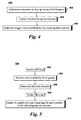
- FIG. 4 is a flow diagram illustrating an updating process 400 according to embodiments of the present invention.
- customers are added or removed from the customer groups as they opt in and out of one or more of the utility programs.
- the customer groups are updated appropriately in step 404.
- the program criteria such as the remaining number of allowable events and the distribution of the event trigger in future periods, for example, are recomputed or updated.
- FIG. 5 shows a flow diagram of a demand response event invocation process 500 according to an exemplary embodiment of the present invention.
- demand response (DR) data is retrieved along with other data relevant to the event trigger criteria.
- DR data can include load forecast information for a DR program based on generation costs, or contingency data such as desired load curtailment over a certain period for a DR program based on contingency events. Sources for this information include the customer database 134, program database 136, DR module 128, EMS module 202, DMS module 210, NMS module 130, and AMI / Internet among others.
- event availability information for each of the groups created for the program is retrieved.
- the demand response schedule is determined in step 506. More particularly, the groups to be included and the time and the duration for each group is determined and scheduled for the demand response event.
- the demand response event is called or invoked.
- the number of remaining events and durations for each group is updated as necessary.
- FIG. 6 shows a flow diagram for determining the demand response schedule of step 506.
- the process 600 starts in step 602.
- step 604 the time period that results in the optimal benefit for the group's event trigger criteria is determined for each group.
- the optimal time period to assign to the group can be solved using Operations Research methodologies such as dynamic programming, stochastic math programming, and simulation, for example.
- the future benefit value of the event trigger criteria for each group is calculated. This future benefit value is based on using the opportunity at a future period and uses the distribution of the event trigger criteria over future time periods.
- the future benefit value for a group can be considered the option value or threshold for invoking the event at the current time.
- the option value or threshold value can be determined using any number of analytical methodologies including the methodology disclosed in U.S. Patent application Serial No.
- step 604 we also calculate the net savings for each group as the difference between the current estimated benefit value and the future expected benefit value from invoking a DR event for the group. The customer group with the largest net savings is then identified. In step 606, it is determined whether the net savings value is greater than 0. If the answer in step 606 is yes, then it implies that it is beneficial to use a DR event for this customer group now rather than save it for a later date. Therefore, processing continues to step 608 and the group is selected to be invoked for the current DR event.
- step 610 the DR data is updated with the estimated response and rebound profile for the selected group, and processing continues to step 612.
- step 612 it is determined whether there are any customer groups that have not yet been included in the DR event. If the answer in step 612 is no, then processing stops at step 614. If the answer in step 612 is yes, then processing returns to step 604. In this iteration of processing the customer groups, the updated DR data is used and only those groups are considered that have not yet been included in the DR event. If the net savings value in step 606 is not greater than 0, then processing continues to step 616 and the group is not included in the DR event for the identified time period. The process stops in step 618.
- FIG. 6 illustrates an exemplary embodiment where the group selection occurs together with the time period selection.
- embodiments of the invention can also be implemented where the group selection occurs prior to the time period selection.
- the grouping and selection process can be implemented in any suitable manner.
- FIG. 7 illustrates an example of what the result of the demand response scheduling process may look like.
- three groups A, C and F are selected for particular times and durations in order to optimize the use of a demand response event according to an exemplary embodiment of the present invention.
- the energy management system and method according to embodiments of the invention allow utilities or service providers to optimize the scheduling and dispatch of demand response events.
- Embodiments of the invention determine the optimal selection of customers to include in the demand response event as well as the times and durations for each event.
Landscapes
- Business, Economics & Management (AREA)
- Engineering & Computer Science (AREA)
- Strategic Management (AREA)
- Finance (AREA)
- Accounting & Taxation (AREA)
- Development Economics (AREA)
- Entrepreneurship & Innovation (AREA)
- Economics (AREA)
- General Physics & Mathematics (AREA)
- Theoretical Computer Science (AREA)
- Marketing (AREA)
- Physics & Mathematics (AREA)
- General Business, Economics & Management (AREA)
- Power Engineering (AREA)
- Game Theory and Decision Science (AREA)
- Data Mining & Analysis (AREA)
- Health & Medical Sciences (AREA)
- Computer Networks & Wireless Communication (AREA)
- Public Health (AREA)
- Water Supply & Treatment (AREA)
- General Health & Medical Sciences (AREA)
- Human Resources & Organizations (AREA)
- Primary Health Care (AREA)
- Tourism & Hospitality (AREA)
- Management, Administration, Business Operations System, And Electronic Commerce (AREA)
- Supply And Distribution Of Alternating Current (AREA)
Abstract
A system (100) and method for receiving demand response data and for grouping customers into customer groups based on the demand response data. One or more of the customer groups is scheduled for a demand response event based on the demand response data and forecast data. The selected customer groups are notified and the demand response is implemented for the selected customer groups.
Description
- Demand response refers to mechanisms used to encourage/induce utility consumers to curtail or shift their individual demand in order to reduce aggregate utility demand during particular time periods. For example, electric utilities employ demand response programs to reduce peak demand for electricity. Demand response programs typically offer customers incentives for agreeing to reduce their demand during certain time periods. Many of these programs (e.g., critical peak pricing) stipulate that the utilities can invoke only a limited number of demand response/curtailment events over a given time period (e.g., 20 per year) and also limit the time duration (e.g., minutes, hours) for each particular event. Further, each demand response event typically includes all of the customers participating in the demand response program. Calling a demand response (DR) event for all customers is likely sufficient when a relatively small fraction of customers are participating. However, as the number of participants increases, utilities can achieve improved benefits by invoking DR events for a subset of participants each time. This will enable the utilities to call events more often without exceeding the contract terms, and will avoid excessive load reductions and/or rebound peaks.
- Given that DR programs typically limit the number of opportunities to reduce load, utilities would like to maximize the benefits for each opportunity / event. These benefits include reducing generation / procurement costs and outages. Due to the complexity of estimating these benefits for a particular opportunity, utilities typically use simple heuristic based trigger criteria, such as temperature or reserve margin, to determine when to invoke a demand response or curtailment event. However, when combined with the current practice of including all participating customers in each event, this approach does not enable utilities to optimize their benefits from the limited opportunities for DR events.
- For these and other reasons, there is a need for the present invention.
- A system and method for receiving demand response data and for grouping customers into customer groups based on the demand response data. One or more of the customer groups is scheduled for a demand response event based on the demand response data and forecast data. The selected customer groups are notified and the demand response is implemented for the selected customer groups.
- The nature and various additional features of the invention will appear more fully upon consideration of the illustrative embodiments of the invention which are schematically set forth in the figures. Like reference numerals represent corresponding parts.
-
FIG. 1 illustrates a utility management system according to an embodiment of the invention; -
FIG. 2 illustrates a utility management system according to another embodiment of the invention; -
FIG. 3 illustrates a flow diagram of a grouping process according to an embodiment of the invention; -
FIG. 4 illustrates a flow diagram of an updating process according to an embodiment of the present invention; -
FIG. 5 illustrates a flow diagram of a demand response scheduling process according to an embodiment of the present invention; -
FIG. 6 illustrates a flow diagram of a demand response event optimization process according to another embodiment of the present invention; and -
FIG. 7 shows a graph of an exemplary group selection according to an exemplary embodiment of the invention; and - While the above-identified drawing figures set forth alternative embodiments, other embodiments of the present invention are also contemplated, as noted in the discussion. In all cases, this disclosure presents illustrated embodiments of the present invention by way of representation and not limitation. Numerous other modifications and embodiments can be devised by those skilled in the art which fall within the scope and spirit of the principles of this invention.
- The embodiments described herein are directed to an energy management system and method that enable utilities to optimize the use of demand response or curtailment events during certain periods of time. While embodiments of the invention will be described in the context of energy or electric utilities and power grid operations, it will be appreciated by those skilled in the art that the system and method can be used for other purposes or utilities as well.
- As used herein, the term "module" refers to software, hardware, or firmware, or any combination of these, or any system, process, or functionality that performs or facilitates the processes described herein.
- The demand response management system and method according to embodiments of the invention allow utilities to optimize the scheduling and dispatch of demand response events. Embodiments of the invention determine the optimal selection of customers to include in the demand response event as well as the times and durations for each customer.
- Demand response programs such as critical peak pricing (CPP), Variable Peak Pricing (VPP), Direct Load Control (DLC), and other various incentive programs are examples of demand response programs with contractual specifications as to when, how often, and the duration that a utility can designate a demand response event for a participating customer. For example, a contract may specify that the utility can invoke up to 15 events per year, where each event will occur between the hours of 12 pm and 6 pm with a maximum of 60 total hours per year. According to embodiments of the invention, the utility can choose to use 10 events of 6 hours each, or 15 events of 4 hours each, or any other such combination of events and hours to stay within the 15 event, 60 hour limitations for each customer.
- In this example, assume that the utility has 100,000 customers participating in the demand response program. In addition, the utility can designate a subset of the participating customers to be included in each event. By using only 50,000 customers per event instead of the full 100,000, for example, the utility can double the total number of events. Day-to-day variation in weather and other factors will also change the most advantageous hours over which to invoke a DR event. For instance, on some days a six hour event may be needed due to continuous hot weather, while on others, relatively fast temperature changes (i.e., due to a front moving in) may reduce the most beneficial number of hours to four. By enabling the optimal selection of the number of customers, along with their specific timing and duration, for any event, embodiments of the invention maximize the utility's benefits from each event opportunity.
- Embodiments of the system and method operate by evaluating the expected benefits (e.g., determined by generation cost, market prices, or other costs to serve load) for the utility or load serving entity for invoking a demand response event during a particular day. This evaluation determines the marginal savings/benefit for each opportunity within the day or period of interest, where an opportunity includes an customer-time period pairing. The time period can be any time period such as minutes or hours, for example. If the estimated marginal benefit of a particular customer-time period exceeds the expected future benefit from holding or saving that opportunity to use in a future event period, then that customer-time period is selected or scheduled for use within the current event period. The marginal benefit calculation incorporates both the expected load reduction for the customer-time period as well as the rebound of that load into subsequent time periods. Based on this analysis, embodiments of the system and method according to the present invention determine the best set of customers and their individually associated time periods for which to designate a demand response event on the current day or period. The set of customers may be staggered across different time periods so as to maximize the total benefits, while ensuring that the marginal benefits of each selected customer-time period exceed the opportunity to use them in the future. The staggering of customers across different time periods is especially useful when large rebound effects exist.
- The expected future benefits of a customer-time period can be calculated based upon the price/cost volatility, relevant forecasts (e.g., weather, load, generation availability, etc.), and other parameters that determine the probability distribution of future benefits. The expected future benefits represent the benefits from utilizing the opportunities in future time periods.
- According to embodiments of the invention, customers are segmented into customer groups, and the decision of whether to invoke a demand response event will be made at the group level so that the event participation decision for a group applies to all of the customers in that group. The number of groups and the size of each group can be determined by each utility or service provider. However, the groupings should meet certain characteristics. For example, each group should be phase balanced, the customers in each group should have similar preferences for event timings and duration, and the size of a group should not be so large that by itself it creates a rebound effect large enough to create a new or nearly new peak, for example. The customer groupings can be updated as necessary to accommodate new programs, contracts or customer participants, and other variables.
- An exemplary energy management system according to an embodiment of the invention is shown in
FIG. 1 . Thesystem 100 includes anenergy management server 102,customer sites 104, and autility 108. In order to facilitate the description of the embodiments of the invention, asingle server 102 and asingle utility source 108 are shown inFIG. 1 . However, it should be understood that embodiments of the invention are not limited to these numbers, and that there can be any number of energy management servers, customer sites, service providers, and control centers in a utility network. In addition, theenergy management server 102 can be arranged at and/or hosted by theutility 108 and/or by any other party. - Each
customer site 104 includes anenergy manager 110 havingprocessor 112, amemory 114, and auser interface 116. Theuser interface 116 can include a keyboard or touch screen, for example, along with a display. Theprocessor 112 runs programs for monitoring and controlling the operation of various customer devices such asloads 118,sensors 120,renewables 122,storage 124, and plug in electric vehicles (PEV) or plug in hybrid electric vehicles (PHEV) 126. Thesensors 120 include meters, thermostats, occupancy sensors, humidity gauges, and other such devices. Therenewable resources 122 can include solar and/or wind power devices, for example. Theprocessor 112 controls the various components using any of a number of interfaces or protocols including Zigbee, Z-Wave, WiFi, or Homeplug, for example. Communication between thecustomer sites 104, theserver 102, and theutility 108 occurs via a WAN (e.g., Internet) 106, WiMAX, broadband, AMI, and/or power line carriers, for example. Communication can also occur via a private network. Any suitable means for communication can be used. - The
energy management server 102 includes a Demand Response (DR)module 128, a Network Management Services (NMS)Module 130, auser interface module 132, a customer database (DB) 134, and a program database (DB) 136. TheNMS module 130 provides communication management and provisioning for theDR module 128, thecustomer sites 104 and theutility 108. Thecustomer database 134 stores data such as historical data for each customer site in the network, for example. The historical data can include information on customer utility usage including load type, time of use (TOU), duration of use, shed or demand response events, for example. The customer usage information stored in thedatabase 134 can be updated periodically (e.g., hourly, daily) with load data including hourly load and hourly price over a twenty four hour period, environmental data including weather information (e.g., temperature, humidity, wind speed, heating and cooling degrees, etc.) and date and time information such as day of the week, season, etc. In addition, thedatabase 134 stores event data for each customer site. More specifically, thedatabase 134 stores historical information on whether a customer site participated in a demand response event, the start time and end time, day of week, season, etc. In addition, the amount of load reduction and rebound are stored indatabase 134. Data related to response forecasting and expected future benefit calculations can also be stored indatabase 134. Theprogram database 136 stores various applications and programs implemented by theenergy management server 102. Theuser interface module 132 provides information to an operator. - In an embodiment of the invention, the
energy management server 102 can be arranged physically and/or logically at one or more utility control centers 200, as shown inFIG. 2 . In addition, theutility control center 200 can include an energy management system (EMS)module 202 that performs load forecasting for the network, and monitors, controls, and optimizes the performance of the generation and transmission system. A Supervisory Control And Data Acquisition (SCADA)module 204 provides real time information at different points in the grid and also provides local controls. An Outage Management System (OMS)module 206 monitors load status information and outage restoration information for thecustomer sites 104 in the network. Some of the functions performed by theOMS module 206 include failure prediction, providing information on the extent of outages and impact to customers, and prioritizing restoration efforts. TheOMS module 206 operates based on a detailed network model of the distribution system that is generated and maintained by a Geographic Information Systems (GIS)module 208. A Distribution Management System (DMS)module 210 provides real-time response to adverse or unstable network conditions by providing information on load status and load response. TheDMS module 210 manages the response to alarms and/or events. Customer information including service contract information, participation in incentive and/or demand response programs, and contract price information, for example, is monitored and controlled by the Customer Information System (CIS)module 212. A Direct Load Control (DLC)module 214 controls and manages customer site devices such as the thermostat - HVAC, water heater, pool pump, washer, dryer, dishwasher, LCD / Plasma TV, plug loads (e.g., computers, computer peripherals / accessories, fax machine, power supplies), refrigerator, and lighting, for example. These are mostly discrete types of devices that have on/off, eco-mode/normal mode, or multiple discrete power saving modes (e.g., dimmable lighting). Customer billing is performed by thebilling module 216. - According to embodiments of the invention, the
DR module 128 utilizes information from thecustomer sites 104, theutility 108 and thedatabases DR module 128 can include response estimation, aggregation, disaggregation, contingency response, outage mitigation, demand dispatch, for example. -
FIG. 3 shows a flow diagram for agrouping process 300 according to embodiments of the invention. Instep 302, theDR module 128 utilizes information received from thecustomer sites 104, theutility 108, and information stored in thedatabases step 304, a number of customer groups are created for the program under consideration based upon certain customer attributes. For example, the system can create customer groups based on geography, types of appliances, load shed windows, event durations, rebound effect or patterns, or any other suitable basis. The customer groups should be phase balanced as well. Instep 308, the customers participating in the program are grouped into the appropriate customer groups created instep 304. The customer groups will be created for each DR program offered by the utility. The number of groups and the number of customers in each group will vary depending on customer participation in the programs. In some embodiments, a customer could belong to multiple customer groups across various programs. Instep 310, an event trigger criteria is identified for the program fromstep 302. For example, an event trigger criteria (representing marginal benefits) for a particular demand response program can include generation cost savings, temperature, reserve margins, and/or any other suitable parameter that measures or represents the value of a DR event to the utility. Step 312 provides for estimating the distribution of each group's event trigger criteria in future periods of time based upon historical data and/or analytical methods, such as any suitable forecasting method. For example, if the event trigger criteria is temperature, the temperature distribution for a future period of time is determined based on historical data or other forecasting method. The information in 312 can be used to calculate a threshold value (i.e., expected future benefits) such that the DR event can be invoked if the event trigger criteria for a group reaches its threshold value. The methodology disclosed inU.S. Patent application Serial No. 12/646,012, filed on Dec. 23, 2009 - While embodiments of the invention are described with respect to one demand response program, it is to be understood that embodiments of the invention also apply to multiple programs that may be offered and the groupings can change based upon the various programs.
-
FIG. 4 is a flow diagram illustrating anupdating process 400 according to embodiments of the present invention. Instep 402, customers are added or removed from the customer groups as they opt in and out of one or more of the utility programs. The customer groups are updated appropriately instep 404. Instep 406, the program criteria such as the remaining number of allowable events and the distribution of the event trigger in future periods, for example, are recomputed or updated. -
FIG. 5 shows a flow diagram of a demand responseevent invocation process 500 according to an exemplary embodiment of the present invention. Instep 502, demand response (DR) data is retrieved along with other data relevant to the event trigger criteria. For example, DR data can include load forecast information for a DR program based on generation costs, or contingency data such as desired load curtailment over a certain period for a DR program based on contingency events. Sources for this information include thecustomer database 134,program database 136,DR module 128,EMS module 202,DMS module 210,NMS module 130, and AMI / Internet among others. Instep 504, event availability information for each of the groups created for the program is retrieved. The demand response schedule is determined instep 506. More particularly, the groups to be included and the time and the duration for each group is determined and scheduled for the demand response event. Instep 508, the demand response event is called or invoked. Instep 510, the number of remaining events and durations for each group is updated as necessary. -
FIG. 6 shows a flow diagram for determining the demand response schedule ofstep 506. Theprocess 600 starts instep 602. Instep 604, the time period that results in the optimal benefit for the group's event trigger criteria is determined for each group. The optimal time period to assign to the group can be solved using Operations Research methodologies such as dynamic programming, stochastic math programming, and simulation, for example. Additionally, the future benefit value of the event trigger criteria for each group is calculated. This future benefit value is based on using the opportunity at a future period and uses the distribution of the event trigger criteria over future time periods. The future benefit value for a group can be considered the option value or threshold for invoking the event at the current time. The option value or threshold value can be determined using any number of analytical methodologies including the methodology disclosed inU.S. Patent application Serial No. 12/646,012, filed on Dec. 23, 2009 step 604, we also calculate the net savings for each group as the difference between the current estimated benefit value and the future expected benefit value from invoking a DR event for the group. The customer group with the largest net savings is then identified. Instep 606, it is determined whether the net savings value is greater than 0. If the answer instep 606 is yes, then it implies that it is beneficial to use a DR event for this customer group now rather than save it for a later date. Therefore, processing continues to step 608 and the group is selected to be invoked for the current DR event. Instep 610, the DR data is updated with the estimated response and rebound profile for the selected group, and processing continues to step 612. Instep 612, it is determined whether there are any customer groups that have not yet been included in the DR event. If the answer instep 612 is no, then processing stops atstep 614. If the answer instep 612 is yes, then processing returns to step 604. In this iteration of processing the customer groups, the updated DR data is used and only those groups are considered that have not yet been included in the DR event. If the net savings value instep 606 is not greater than 0, then processing continues to step 616 and the group is not included in the DR event for the identified time period. The process stops instep 618. -
FIG. 6 illustrates an exemplary embodiment where the group selection occurs together with the time period selection. However, embodiments of the invention can also be implemented where the group selection occurs prior to the time period selection. The grouping and selection process can be implemented in any suitable manner. -
FIG. 7 illustrates an example of what the result of the demand response scheduling process may look like. In the example shown, three groups A, C and F are selected for particular times and durations in order to optimize the use of a demand response event according to an exemplary embodiment of the present invention. - Although embodiments of the invention have been described with reference to processing of a single demand response program, the invention is not limited in this regard. The grouping and scheduling according to embodiments of the present invention can be performed for multiple programs based on different event trigger criteria.
- The energy management system and method according to embodiments of the invention allow utilities or service providers to optimize the scheduling and dispatch of demand response events. Embodiments of the invention determine the optimal selection of customers to include in the demand response event as well as the times and durations for each event.
- While only certain features of the invention have been illustrated and described herein, many modifications and changes will occur to those skilled in the art. It is, therefore, to be understood that the appended claims are intended to cover all such modifications and changes as fall within the true spirit of the invention.
- Various aspects and embodiments of the present invention are defined by the following numbered clauses:
- 1. A system, comprising:
- a database to store demand response data;
- a demand response module to group customers into customer groups based on the demand response data, and to schedule one or more of the customer groups for a demand response event based on the demand response data and forecast data; and
- a controller to implement the demand response event for the one or more customer groups scheduled for the demand response event.
- 2. The system of clause 1, further comprising:
- a monitor computer to monitor power grid operations.
- 3. The system of clause 1 or clause 2, wherein the demand response module establishes the customer groups based on demand response program parameters for at least one demand response program.
- 4. The system of any preceding clause, wherein the demand response module assigns the customers into the customer groups based on the demand response data.
- 5. The system of any preceding clause, wherein the demand response data includes at least one of demand response program parameters, load and demand characteristics of the customers, rebound parameters of the customers, or customer attributes including geographic location, power phase, types of appliances, and load shed windows.
- 6. The system of any preceding clause, wherein the forecast data includes at least one of weather data, price data, or load data.
- 7. A method, comprising:
- receiving demand response data;
- grouping customers into customer groups based on the demand response data;
- scheduling one or more of the customer groups for a demand response event based on the demand response data and forecast data;
- notifying the one or more customer groups of the demand response event; and
- implementing the demand response event for the one or more customer groups.
- 8. The method of clause 7 further comprising:
- determining program parameters for each available demand response program from the demand response data;
- establishing the customer groups for each available demand response program; and
- assigning the customers to the customer groups based on the demand response data.
- 9. The method of clause 7 or clause 8, wherein each of the customers belongs to at least one of the customer groups.
- 10. The method of any of clauses 7 to 9, further comprising:
- identifying a demand response program from available demand response programs;
- identifying an event trigger criteria for the demand response program; and
- estimating a distribution of the event trigger criteria in future periods of time.
- 11. The method of any of clauses 7 to 10, further comprising:
- updating the customer groups and the distribution as a number of customers changes.
- 12. The method of any of clauses 7 to 11, further comprising:
- determining a customer group from the customer groups corresponding to optimal performance benefits based on a difference between a current benefit of including the customer group in the demand response event and an estimated future benefit of saving the customer group for inclusion in a future demand response event;
- comparing the optimal performance benefits of the customer group with a predetermined threshold; and
- selecting the customer group for the demand response event when the optimal performance benefits are greater than the predetermined threshold.
- 13. The method of any of clauses 7 to 12, further comprising:
- updating utility forecast information based on an estimated use reduction and rebound corresponding to the customer group selected for the demand response event.
- 14. The method of any of clauses 7 to 13, further comprising:
- repeating the determining, comparing and selecting process until all of the customer groups are processed.
- 15. A computer-readable medium comprising computer-readable instructions of a computer program that, when executed by a processor, cause the processor to perform a method, the method comprising:
- receiving demand response data;
- grouping customers into customer groups based on the demand response data;
- scheduling one or more of the customer groups for a demand response event based on the demand response data and forecast data;
- notifying the one or more customer groups of the demand response event; and
- implementing the demand response event for the one or more customer groups.
- 16. The computer-readable medium of
clause 15, the method further comprising:- determining program parameters for each available demand response program from the demand response data;
- establishing the customer groups for each available demand response program; and
- assigning the customers to the customer groups based on the demand response data.
- 17. The computer-readable medium of
clause 15 orclause 16, wherein each of the customers belongs to at least one of the customer groups. - 18. The computer-readable medium of any of
clauses 15 to 17, the method further comprising:- identifying a demand response program from available demand response programs;
- identifying an event trigger criteria for the demand response program; and
- estimating a distribution of the event trigger criteria in future periods of time.
- 19. The computer-readable medium of any of
clauses 15 to 18, the method further comprising:- updating the customer groups and the event trigger criteria distribution as a number of customers changes.
- 20. The computer readable medium of any of
clauses 15 to 19, the method further comprising:- determining a customer group from the customer groups corresponding to optimal performance benefits based on a difference between a current benefit of including the customer group in the demand response event and an estimated future benefit of saving the customer group for inclusion in a future demand response event;
- comparing the optimal performance benefits of the customer group with a predetermined threshold; and
- selecting the customer group for the demand response event when the optimal performance benefits are greater than the predetermined threshold.
- 21. The computer-readable medium of any of
clauses 15 to 20, the method further comprising:- updating utility forecast information based on an estimated use reduction and rebound corresponding to the customer group selected for the demand response event.
- 22. The computer-readable medium of any of
clauses 15 to 21, further comprising:- repeating the determining, comparing and selecting process until all of the customer groups are processed.
Claims (15)
- A system, comprising:a database to store demand response data (134, 136);a demand response module (128) to group customers into customer groups based on the demand response data, and to schedule one or more of the customer groups for a demand response event based on the demand response data and forecast data; anda controller (102) to implement the demand response event for the one or more customer groups scheduled for the demand response event.
- The system of claim 1, further comprising:a monitor computer (200) to monitor power grid operations.
- The system of claim 1 or claim 2, wherein the demand response module (128) establishes the customer groups based on demand response program parameters for at least one demand response program.
- The system of any preceding claim, wherein the demand response module (128) assigns the customers into the customer groups based on the demand response data.
- The system of any preceding claim, wherein the demand response data includes at least one of demand response program parameters, load and demand characteristics of the customers, rebound parameters of the customers, or customer attributes including geographic location, power phase, types of appliances, and load shed windows.
- The system of any preceding claim, wherein the forecast data includes at least one of weather data, price data, or load data.
- A method, comprising:receiving demand response data;grouping customers into customer groups based on the demand response data;scheduling one or more of the customer groups for a demand response event based on the demand response data and forecast data;notifying the one or more customer groups of the demand response event; andimplementing the demand response event for the one or more customer groups.
- The method of claim 7 further comprising:determining program parameters for each available demand response program from the demand response data;establishing the customer groups for each available demand response program; andassigning the customers to the customer groups based on the demand response data.
- The method of claim 7 or claim 8, wherein each of the customers belongs to at least one of the customer groups.
- The method of any of claims 7 to 9, further comprising:identifying a demand response program from available demand response programs;identifying an event trigger criteria for the demand response program; andestimating a distribution of the event trigger criteria in future periods of time.
- The method of any of claims 7 to 10, further comprising:updating the customer groups and the distribution as a number of customers changes.
- The method of any of claims 7 to 11, further comprising:determining a customer group from the customer groups corresponding to optimal performance benefits based on a difference between a current benefit of including the customer group in the demand response event and an estimated future benefit of saving the customer group for inclusion in a future demand response event;comparing the optimal performance benefits of the customer group with a predetermined threshold; andselecting the customer group for the demand response event when the optimal performance benefits are greater than the predetermined threshold.
- The method of any of claims 7 to 12, further comprising:updating utility forecast information based on an estimated use reduction and rebound corresponding to the customer group selected for the demand response event.
- The method of any of claims 7 to 13, further comprising:repeating the determining, comparing and selecting process until all of the customer groups are processed.
- A computer-readable medium comprising computer-readable instructions of a computer program that, when executed by a processor, cause the processor to perform a method, the method comprising:receiving demand response data;grouping customers into customer groups based on the demand response data;scheduling one or more of the customer groups for a demand response event based on the demand response data and forecast data;notifying the one or more customer groups of the demand response event; andimplementing the demand response event for the one or more customer groups.
Applications Claiming Priority (2)
| Application Number | Priority Date | Filing Date | Title |
|---|---|---|---|
| US32572810P | 2010-04-19 | 2010-04-19 | |
| US12/790,655 US20110258018A1 (en) | 2010-04-19 | 2010-05-28 | System and method for scheduling demand response events in a network |
Publications (1)
| Publication Number | Publication Date |
|---|---|
| EP2378483A1 true EP2378483A1 (en) | 2011-10-19 |
Family
ID=44117469
Family Applications (1)
| Application Number | Title | Priority Date | Filing Date |
|---|---|---|---|
| EP11161983A Withdrawn EP2378483A1 (en) | 2010-04-19 | 2011-04-12 | System and method for scheduling demand response events in a network |
Country Status (7)
| Country | Link |
|---|---|
| US (1) | US20110258018A1 (en) |
| EP (1) | EP2378483A1 (en) |
| JP (1) | JP2011229374A (en) |
| AU (1) | AU2011201712A1 (en) |
| BR (1) | BRPI1102021A2 (en) |
| CA (1) | CA2736645A1 (en) |
| NZ (1) | NZ592295A (en) |
Cited By (10)
| Publication number | Priority date | Publication date | Assignee | Title |
|---|---|---|---|---|
| WO2013074586A3 (en) * | 2011-11-14 | 2013-10-31 | Siemens Corporation | Method and system for improving the effectiveness of planned power consumption demand response events |
| WO2014149993A1 (en) | 2013-03-15 | 2014-09-25 | Nest Labs, Inc. | Utility portals for managing demand-response events |
| EP2854250A2 (en) | 2013-09-16 | 2015-04-01 | BKW Energie AG | Method for analysis of an aggregated consumption signal and for load control in an electrical power system |
| EP2713321A3 (en) * | 2012-09-28 | 2015-09-30 | General Electric Company | Method and system for demand response management |
| JP2017146898A (en) * | 2016-02-19 | 2017-08-24 | 住友電気工業株式会社 | Power consumption management device and power consumption management program |
| US9810442B2 (en) | 2013-03-15 | 2017-11-07 | Google Inc. | Controlling an HVAC system in association with a demand-response event with an intelligent network-connected thermostat |
| US10101050B2 (en) | 2015-12-09 | 2018-10-16 | Google Llc | Dispatch engine for optimizing demand-response thermostat events |
| CN109672543A (en) * | 2019-01-08 | 2019-04-23 | 平安科技(深圳)有限公司 | Group event management method and device |
| US10438304B2 (en) | 2013-03-15 | 2019-10-08 | Google Llc | Systems, apparatus and methods for managing demand-response programs and events |
| CN111697704A (en) * | 2020-07-04 | 2020-09-22 | 李英超 | Power supply information processing method of smart power grid |
Families Citing this family (46)
| Publication number | Priority date | Publication date | Assignee | Title |
|---|---|---|---|---|
| US20120136496A1 (en) * | 2010-11-30 | 2012-05-31 | General Electric Company | System and method for estimating demand response in electric power systems |
| US20120246040A1 (en) * | 2011-03-21 | 2012-09-27 | Nathan Bowman Littrell | Systems and methods for generating a bill |
| GB2479060B (en) * | 2011-03-24 | 2012-05-02 | Reactive Technologies Ltd | Energy consumption management |
| US9125010B2 (en) | 2011-10-27 | 2015-09-01 | General Electric Company | Systems and methods to implement demand response events |
| US20130110970A1 (en) * | 2011-10-27 | 2013-05-02 | Mark Joseph Meyerhofer | Systems and methods to provide demand response events |
| US8972071B2 (en) | 2011-10-27 | 2015-03-03 | General Electric Company | Systems and methods to predict a reduction of energy consumption |
| US9082141B2 (en) | 2011-10-27 | 2015-07-14 | General Electric Company | Systems and methods to implement demand response events |
| JP5899830B2 (en) * | 2011-11-09 | 2016-04-06 | ソニー株式会社 | Power management apparatus, power management method, and demand notification apparatus |
| US8880235B2 (en) * | 2011-11-15 | 2014-11-04 | Palo Alto Research Center Incorporated | Staggering and feathering of demand response and energy supply change in a managed electrical system |
| JP5348229B2 (en) * | 2011-12-01 | 2013-11-20 | ダイキン工業株式会社 | Intermediate device |
| JP5632412B2 (en) * | 2012-03-21 | 2014-11-26 | 株式会社東芝 | Electric power reduction request plan planning apparatus and method |
| US9209625B2 (en) * | 2012-04-20 | 2015-12-08 | General Electric Company | Method and system to co-optimize utilization of demand response and energy storage resources |
| JP5909555B2 (en) * | 2012-08-27 | 2016-04-26 | 株式会社日立製作所 | Customer cooperation support device |
| US9124132B2 (en) | 2012-08-31 | 2015-09-01 | Siemens Industry, Inc. | Automated demand response gateway |
| GB2505929A (en) * | 2012-09-14 | 2014-03-19 | Pod Point Holiding Ltd | Method and system for predictive load shedding on a power grid |
| US20140203092A1 (en) * | 2013-01-24 | 2014-07-24 | General Electric Company | Communicating thermostat recovery algorithm |
| US9865024B2 (en) * | 2013-03-15 | 2018-01-09 | Open Access Technology International, Inc. | Systems and methods of determining optimal scheduling and dispatch of power resources |
| US20140278687A1 (en) * | 2013-03-15 | 2014-09-18 | Gridglo Llc | System and Method for Optimizing A Demand Response Event |
| AU2014252667A1 (en) * | 2013-04-12 | 2015-09-24 | Generac Power Systems, Inc. | System and method for performing demand response optimizations |
| JP2014207793A (en) | 2013-04-15 | 2014-10-30 | 株式会社東芝 | Request control device, method, and program |
| JP2014220892A (en) * | 2013-05-07 | 2014-11-20 | 株式会社東芝 | Information issue device, information issue method, and program |
| US10432753B2 (en) | 2013-08-16 | 2019-10-01 | Fujitsu Limited | Demand response event dissemination system and method |
| JP6302197B2 (en) * | 2013-09-20 | 2018-03-28 | 株式会社東芝 | Electric power supply and demand control device and electric power supply and demand control method |
| JP6232275B2 (en) * | 2013-12-13 | 2017-11-15 | 株式会社日立製作所 | Supply and demand adjustment method and system |
| US9953285B2 (en) * | 2014-01-22 | 2018-04-24 | Fujitsu Limited | Residential and small and medium business demand response |
| US10152683B2 (en) | 2014-01-22 | 2018-12-11 | Fujistu Limited | Demand response event assessment |
| US20150213466A1 (en) * | 2014-01-24 | 2015-07-30 | Fujitsu Limited | Demand response aggregation optimization |
| US20150268686A1 (en) * | 2014-03-19 | 2015-09-24 | University Of Florida Research Foundation, Inc. | Social networking reducing peak power consumption in smart grid |
| US10115120B2 (en) | 2014-05-12 | 2018-10-30 | Fujitsu Limited | Dynamic demand response event assessment |
| US20160124411A1 (en) * | 2014-10-31 | 2016-05-05 | Qualcomm Incorporated | Distributed energy demand management |
| WO2016084313A1 (en) * | 2014-11-27 | 2016-06-02 | 日本電気株式会社 | Power demand adjustment system, demand adjustment device, group generation device, and group generation method |
| JP6083452B2 (en) * | 2015-05-19 | 2017-02-22 | ダイキン工業株式会社 | Management device for multiple air conditioners |
| JP6544720B2 (en) * | 2015-06-17 | 2019-07-17 | パナソニックIpマネジメント株式会社 | Management apparatus, management method, and management program |
| US10438303B2 (en) * | 2015-09-01 | 2019-10-08 | Fujitsu Limited | Optimization and distribution of coupons in residential demand response |
| US10615596B2 (en) * | 2015-09-30 | 2020-04-07 | Siemens Aktiengesellschaft | Systems, methods and apparatus for an improved aggregation engine for a demand response management system |
| JP6653153B2 (en) * | 2015-10-01 | 2020-02-26 | 株式会社日立製作所 | Power demand adjustment plan management device |
| JP6742813B2 (en) * | 2016-05-20 | 2020-08-19 | 株式会社日立製作所 | Demand forecasting system and demand forecasting method |
| US20180175666A1 (en) * | 2016-12-20 | 2018-06-21 | Ecojiva, LLC | Electrical load management system |
| US12261432B2 (en) | 2016-12-20 | 2025-03-25 | Ecojiva Llc | Electrical load management system |
| US10109987B2 (en) * | 2017-01-18 | 2018-10-23 | Coulomb Inc. | Energy management apparatus to upgrade and control an existing circuit breaker panel |
| US10867315B2 (en) | 2017-02-20 | 2020-12-15 | Honda Motor Co., Ltd. | System and method for implementing a demand response event with variable incentives for vehicles |
| US10495333B2 (en) | 2017-02-24 | 2019-12-03 | Honeywell International Inc. | Providing demand response |
| CN109378898B (en) * | 2018-09-30 | 2022-06-17 | 国网天津市电力公司电力科学研究院 | Intelligent regulation and control system and method for distribution transformer area |
| WO2021262502A1 (en) * | 2020-06-26 | 2021-12-30 | X Development Llc | Secure electrical power grid simulation |
| US11735920B2 (en) * | 2021-03-12 | 2023-08-22 | International Business Machines Corporation | Cognitive framework for improving responsivity in demand response programs |
| JP2024055509A (en) * | 2022-10-07 | 2024-04-18 | 京セラ株式会社 | Power management system and power management method |
Citations (5)
| Publication number | Priority date | Publication date | Assignee | Title |
|---|---|---|---|---|
| US20080039979A1 (en) * | 2006-08-10 | 2008-02-14 | V2 Green Inc. | Smart Islanding and Power Backup in a Power Aggregation System for Distributed Electric Resources |
| US20080040223A1 (en) * | 2006-08-10 | 2008-02-14 | V2 Green Inc. | Electric Resource Module in a Power Aggregation System for Distributed Electric Resources |
| US20080052145A1 (en) * | 2006-08-10 | 2008-02-28 | V2 Green, Inc. | Power Aggregation System for Distributed Electric Resources |
| US20090281885A1 (en) * | 2008-05-08 | 2009-11-12 | International Business Machines Corporation | Using virtual environment incentives to reduce real world energy usage |
| EP2159749A1 (en) * | 2008-08-20 | 2010-03-03 | Alcatel, Lucent | Method of controlling a power grid |
Family Cites Families (5)
| Publication number | Priority date | Publication date | Assignee | Title |
|---|---|---|---|---|
| US4023043A (en) * | 1974-08-16 | 1977-05-10 | Megatherm Corporation | Computerized peak-shaving system for alleviating electric utility peak loads |
| US8855829B2 (en) * | 2007-01-03 | 2014-10-07 | Gridpoint, Inc. | Method for controlling energy resources |
| KR20090126104A (en) * | 2008-06-03 | 2009-12-08 | 서울대학교산학협력단 | Power demand management method and system |
| US8260468B2 (en) * | 2008-06-25 | 2012-09-04 | Versify Solutions, Inc. | Aggregator, monitor, and manager of distributed demand response |
| US8068938B2 (en) * | 2009-05-15 | 2011-11-29 | General Electric Company | Method and system for managing a load demand on an electrical grid |
-
2010
- 2010-05-28 US US12/790,655 patent/US20110258018A1/en not_active Abandoned
-
2011
- 2011-04-06 JP JP2011084137A patent/JP2011229374A/en not_active Withdrawn
- 2011-04-07 CA CA2736645A patent/CA2736645A1/en not_active Abandoned
- 2011-04-12 EP EP11161983A patent/EP2378483A1/en not_active Withdrawn
- 2011-04-15 AU AU2011201712A patent/AU2011201712A1/en not_active Abandoned
- 2011-04-15 NZ NZ592295A patent/NZ592295A/en not_active IP Right Cessation
- 2011-04-18 BR BRPI1102021-0A2A patent/BRPI1102021A2/en not_active Application Discontinuation
Patent Citations (5)
| Publication number | Priority date | Publication date | Assignee | Title |
|---|---|---|---|---|
| US20080039979A1 (en) * | 2006-08-10 | 2008-02-14 | V2 Green Inc. | Smart Islanding and Power Backup in a Power Aggregation System for Distributed Electric Resources |
| US20080040223A1 (en) * | 2006-08-10 | 2008-02-14 | V2 Green Inc. | Electric Resource Module in a Power Aggregation System for Distributed Electric Resources |
| US20080052145A1 (en) * | 2006-08-10 | 2008-02-28 | V2 Green, Inc. | Power Aggregation System for Distributed Electric Resources |
| US20090281885A1 (en) * | 2008-05-08 | 2009-11-12 | International Business Machines Corporation | Using virtual environment incentives to reduce real world energy usage |
| EP2159749A1 (en) * | 2008-08-20 | 2010-03-03 | Alcatel, Lucent | Method of controlling a power grid |
Cited By (22)
| Publication number | Priority date | Publication date | Assignee | Title |
|---|---|---|---|---|
| WO2013074586A3 (en) * | 2011-11-14 | 2013-10-31 | Siemens Corporation | Method and system for improving the effectiveness of planned power consumption demand response events |
| EP2713321A3 (en) * | 2012-09-28 | 2015-09-30 | General Electric Company | Method and system for demand response management |
| US10832266B2 (en) | 2013-03-15 | 2020-11-10 | Google Llc | Streamlined utility portals for managing demand-response events |
| US10438304B2 (en) | 2013-03-15 | 2019-10-08 | Google Llc | Systems, apparatus and methods for managing demand-response programs and events |
| EP2972654A4 (en) * | 2013-03-15 | 2017-02-01 | Google, Inc. | Utility portals for managing demand-response events |
| US11739968B2 (en) | 2013-03-15 | 2023-08-29 | Google Llc | Controlling an HVAC system using an optimal setpoint schedule during a demand-response event |
| US9807099B2 (en) | 2013-03-15 | 2017-10-31 | Google Inc. | Utility portals for managing demand-response events |
| US9810442B2 (en) | 2013-03-15 | 2017-11-07 | Google Inc. | Controlling an HVAC system in association with a demand-response event with an intelligent network-connected thermostat |
| AU2021202715B2 (en) * | 2013-03-15 | 2022-08-04 | Google Llc | Utility portals for managing demand-response events |
| US11308508B2 (en) | 2013-03-15 | 2022-04-19 | Google Llc | Utility portals for managing demand-response events |
| US10367819B2 (en) | 2013-03-15 | 2019-07-30 | Google Llc | Streamlined utility portals for managing demand-response events |
| US11282150B2 (en) | 2013-03-15 | 2022-03-22 | Google Llc | Systems, apparatus and methods for managing demand-response programs and events |
| US10581862B2 (en) | 2013-03-15 | 2020-03-03 | Google Llc | Utility portals for managing demand-response events |
| US10718539B2 (en) | 2013-03-15 | 2020-07-21 | Google Llc | Controlling an HVAC system in association with a demand-response event |
| AU2019201286B2 (en) * | 2013-03-15 | 2021-02-04 | Google Llc | Utility portals for managing demand-response events |
| WO2014149993A1 (en) | 2013-03-15 | 2014-09-25 | Nest Labs, Inc. | Utility portals for managing demand-response events |
| EP2854250A2 (en) | 2013-09-16 | 2015-04-01 | BKW Energie AG | Method for analysis of an aggregated consumption signal and for load control in an electrical power system |
| US10101050B2 (en) | 2015-12-09 | 2018-10-16 | Google Llc | Dispatch engine for optimizing demand-response thermostat events |
| JP2017146898A (en) * | 2016-02-19 | 2017-08-24 | 住友電気工業株式会社 | Power consumption management device and power consumption management program |
| CN109672543A (en) * | 2019-01-08 | 2019-04-23 | 平安科技(深圳)有限公司 | Group event management method and device |
| CN111697704A (en) * | 2020-07-04 | 2020-09-22 | 李英超 | Power supply information processing method of smart power grid |
| CN111697704B (en) * | 2020-07-04 | 2021-05-11 | 李英超 | A method for processing power supply information of smart grid |
Also Published As
| Publication number | Publication date |
|---|---|
| CA2736645A1 (en) | 2011-10-19 |
| US20110258018A1 (en) | 2011-10-20 |
| BRPI1102021A2 (en) | 2013-12-24 |
| NZ592295A (en) | 2012-11-30 |
| AU2011201712A1 (en) | 2011-11-10 |
| JP2011229374A (en) | 2011-11-10 |
Similar Documents
| Publication | Publication Date | Title |
|---|---|---|
| EP2378483A1 (en) | System and method for scheduling demand response events in a network | |
| EP2458703A2 (en) | System and method for estimating demand response in electric power systems | |
| AU2010257261B2 (en) | Method and system for demand response management in a network | |
| US9209625B2 (en) | Method and system to co-optimize utilization of demand response and energy storage resources | |
| US10816948B2 (en) | System, apparatus and method for energy management, for usage by consumers of energy from electric utility service providers, and monitoring and management of same | |
| EP2296246B1 (en) | Method and system for demand response in a distribution network | |
| EP2560136A1 (en) | Method, system and computer program product for scheduling demand events | |
| US20130066482A1 (en) | Apparatus and method for executing energy demand response process in an electrical power network | |
| Zhong et al. | Integrated dispatch of generation and load: A pathway towards smart grids | |
| KR20120112155A (en) | Systems and methods for forecasting electrical load | |
| KR20120016133A (en) | System and method for estimating and providing expedited operational reserve energy capacity using active load management | |
| WO2013165875A1 (en) | Grid resource scheduling | |
| AU2013234386A1 (en) | Method and system for demand response management | |
| EP2503503A1 (en) | Systems and methods for generating a utility bill | |
| EP2503504A1 (en) | Systems and methods for generating a bill | |
| EP4258501A1 (en) | Grid control | |
| Shantanu et al. | Scheduling of residential appliances for demand response considering customer satisfaction | |
| Manohar et al. | A novel design of user responsive smart meter integrated automated EMS inn SCADA interfaced smart grid |
Legal Events
| Date | Code | Title | Description |
|---|---|---|---|
| AK | Designated contracting states |
Kind code of ref document: A1 Designated state(s): AL AT BE BG CH CY CZ DE DK EE ES FI FR GB GR HR HU IE IS IT LI LT LU LV MC MK MT NL NO PL PT RO RS SE SI SK SM TR |
|
| AX | Request for extension of the european patent |
Extension state: BA ME |
|
| PUAI | Public reference made under article 153(3) epc to a published international application that has entered the european phase |
Free format text: ORIGINAL CODE: 0009012 |
|
| 17P | Request for examination filed |
Effective date: 20120419 |
|
| STAA | Information on the status of an ep patent application or granted ep patent |
Free format text: STATUS: THE APPLICATION IS DEEMED TO BE WITHDRAWN |
|
| 18D | Application deemed to be withdrawn |
Effective date: 20141101 |