EP2378218A2 - Air conditioning device - Google Patents
Air conditioning device Download PDFInfo
- Publication number
- EP2378218A2 EP2378218A2 EP11162520A EP11162520A EP2378218A2 EP 2378218 A2 EP2378218 A2 EP 2378218A2 EP 11162520 A EP11162520 A EP 11162520A EP 11162520 A EP11162520 A EP 11162520A EP 2378218 A2 EP2378218 A2 EP 2378218A2
- Authority
- EP
- European Patent Office
- Prior art keywords
- condensate drain
- air conditioning
- housing
- tongue
- conditioning system
- Prior art date
- Legal status (The legal status is an assumption and is not a legal conclusion. Google has not performed a legal analysis and makes no representation as to the accuracy of the status listed.)
- Granted
Links
Images


Classifications
-
- F—MECHANICAL ENGINEERING; LIGHTING; HEATING; WEAPONS; BLASTING
- F24—HEATING; RANGES; VENTILATING
- F24F—AIR-CONDITIONING; AIR-HUMIDIFICATION; VENTILATION; USE OF AIR CURRENTS FOR SCREENING
- F24F13/00—Details common to, or for air-conditioning, air-humidification, ventilation or use of air currents for screening
- F24F13/20—Casings or covers
-
- B—PERFORMING OPERATIONS; TRANSPORTING
- B60—VEHICLES IN GENERAL
- B60H—ARRANGEMENTS OF HEATING, COOLING, VENTILATING OR OTHER AIR-TREATING DEVICES SPECIALLY ADAPTED FOR PASSENGER OR GOODS SPACES OF VEHICLES
- B60H1/00—Heating, cooling or ventilating [HVAC] devices
- B60H1/00507—Details, e.g. mounting arrangements, desaeration devices
- B60H1/00514—Details of air conditioning housings
- B60H1/00528—Connections between housing parts
-
- B—PERFORMING OPERATIONS; TRANSPORTING
- B60—VEHICLES IN GENERAL
- B60H—ARRANGEMENTS OF HEATING, COOLING, VENTILATING OR OTHER AIR-TREATING DEVICES SPECIALLY ADAPTED FOR PASSENGER OR GOODS SPACES OF VEHICLES
- B60H1/00—Heating, cooling or ventilating [HVAC] devices
- B60H1/32—Cooling devices
- B60H1/3233—Cooling devices characterised by condensed liquid drainage means
-
- F—MECHANICAL ENGINEERING; LIGHTING; HEATING; WEAPONS; BLASTING
- F24—HEATING; RANGES; VENTILATING
- F24F—AIR-CONDITIONING; AIR-HUMIDIFICATION; VENTILATION; USE OF AIR CURRENTS FOR SCREENING
- F24F13/00—Details common to, or for air-conditioning, air-humidification, ventilation or use of air currents for screening
- F24F13/22—Means for preventing condensation or evacuating condensate
Definitions
- the invention relates to an air conditioner with an at least two-part or multi-part housing, wherein the two housing parts are connected to each other via a tongue and groove and the housing has a condensate drain.
- At least two or more parts means that the housing can consist of two parts or more than two parts.
- the invention is therefore based on the object to provide an air conditioner, which allows a reduction in the time required and the cost of materials in the production of the air conditioning and still allows a complete automatic process flow.
- the object is achieved in that the condensate drain is integrated in at least one housing part adjacent to the tongue and groove.
- This has the advantage that the condensate drain is already completely formed and integrated with the housing part of the air conditioner.
- the condensate drain is formed at the same time on the housing of the air conditioner.
- the condensate drain is integrally formed and completely integrated in a housing part.
- the condensate drain is formed in two parts, wherein each part of the condensate drain is connected to a housing part and the two parts of the condensate drain are connected to each other via the tongue and groove.
- the housing separation runs exactly through the condensate drain, condensate drain and housing are connected via the tongue and groove simultaneously in a single step. Since each housing part contains a part of the condensate drain, the condensate drain is simply made when assembling the housing as a whole.
- the condensate drain consists of an approximately flat plate, which, in particular centrally, has a continuous opening.
- This newly designed plate is approximately perpendicular to the tongue and groove, the opening is designed to be continuous to divert the condensate from the air conditioning system to the environment.
- the newly designed plate allows the finished air conditioning system is inserted into the vehicle so that it is simply placed above a vehicle opening that connects the condensate drain with the environment.
- a part of the planar plate is integrated with each housing part, which has half of the continuous opening, wherein the opening points in the direction of the tongue and groove, while the opening is integrated into the tongue and groove. Due to this approach, a use of flat tools is possible, which simply put together the two parts of the newly formed plate with the tongue and groove by attacking parallel to the plate, the tools used are structurally simple, since they matched the geometry of the flat plate are.
- each housing part is formed integrally with the condensate drain or part of the condensate drain. This simplifies the production of the housing part or the condensate drain, which need not be produced in two different operations, but are built in a common manufacturing process.
- the housing part formed integrally with the condensate drain or a part of the condensate drain is made of plastic.
- the use of plastic reduces the weight of the air conditioning system and it can be produced in a single step a variety of forms of housing and condensate drain.
- the housing part formed in one piece with the condensate drain or part of the condensate drain is produced in an injection molding process.
- housing part and condensate drain can be integrated in a particularly simple manner and then only have to be connected by the tongue and groove.
- each housing part has a condensed water slope, which opens into the condensate drain.
- a condensed water slope has the advantage that the condensate forming on the evaporator of the air conditioning system is directed specifically into the condensate drain and is discharged from this to the environment.
- the tongue-and-groove spring is designed to be watertight at least in the region of the condensate drain. This ensures that the condensate does not spread in the housing, but drains specifically into the opening of the condensate drain. A leakage of condensate through the tongue and groove is thus reliably prevented.
- the tongue and groove is welded.
- an ultrasonic welding method is used, By the welded tongue and groove, a particularly dense condensate drain is produced. This is done in particular in the area of the housing of the air conditioning, where the condensation forms and is discharged.
- the tongue and groove at least opposite the condensate drain on a sealing element. Also by such a sealing element, the waterproofness is reliably ensured in the area of the condensate drain.
- the additional sealing element is inserted between the housing part or part of the condensate drain and the tongue and groove and compressed during compression of the housing parts with the tongue and groove.
- the sealing element is formed by a sealing cord, which only has to be inserted and pressed into the groove spring.
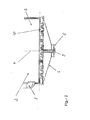
- FIG. 1 is an air conditioner 1 dargesteilt, which is also referred to as air conditioning.
- the air conditioner 1 consists of two housing parts 2 and 3, which are interconnected by a housing connection 4 or housing separation 4. At the lower end of the air conditioner 1, a condensate drain 5 is arranged. On the first part 2 of the housing, a tube group 8 is arranged, while on the second part 3 of the housing, an air inlet housing 7 is fixed, through which the air is supplied to the environment or from the passenger compartment of the air conditioner 1.
- the two parts 2 and 3 of the housing of the air conditioner 1 enclose the parts which are necessary for the operation of the air conditioner 1. For the sake of simplicity, only the evaporator 10 is shown, which is uniformly received by both parts 2, 3.
- Both the housing part 2 and the housing part 3 have a condensate drainage slope 6, to which the condensate drain 5 fires. How out FIG. 1 can be seen, the housing separation 4 passes through the condensate drain 5 and divides this into two parts.
- the housing part 2 next to the tube group 8 includes the condensate water slope 6 and half of the condensate drain 5.
- the housing connection 4 is realized by a tongue and groove connection, also called 9 for short.
- a tongue and groove connection also called 9 for short.
- a part of a groove and the other part of a spring which are plugged into each other.
- FIG. 2 is the area just described the air conditioning 1 shown in more detail.
- the housing connection 4 between the housing parts 2 and 3 is realized by a tongue and groove 9, which also connects the condensate drain 5, which consists of two parts, each having a half-opening part of the condensate drain 5 on one of the two housing parts 2 and 3 of the air conditioner 1 is attached.
- the condensate drain 5 consists of a flat surface 5a, which encloses an opening 5b.
- FIG. 3 clarifies once again the structure of the condensate drain 5 with the flat plate 5a and the opening 5b, To better illustrate the condensate outlet 5, was in the FIG. 3 omitted on the presentation of the housing parts 2 and 3. But it is further pointed out that the condensate drain 5 is part of the housing part 2 and the housing part 3.
- the housing parts 2 and 3 are made of plastic and are produced in an injection molding process together with the condensate drain 5. This results in a single fully integrated component, at which the parts are necessary, which are necessary for the realization of the housing.
- the Condensate drain 5 is connected via a tongue and groove 9, wherein the tongue and groove 9 is welded in the region of the condensate drain 5.
- ultrasonic welding devices are preferably used. With these welded seams, a high water-tightness of the condensate drain 5 is achieved and ensures that the condensate is discharged through the opening 5b from the air conditioner 1 alone.
- the condensate drain 5 is again shown from the inside of the air conditioner 1. Again, it is once again clarified that the parts of the plate 5a of the condensate drain 5 are inserted into the tongue and groove 9 and welded there. Because of this flat design of the plate 5a simple tools can be attached to the tongue and groove 9, wherein the plate 5a is welded to both sides of the tongue and groove 9. In addition, the condensate drain 5 still has two support elements 5c, with which the condensate drain is supported on the housing parts 2 and 3 of the air conditioner 1, which is particularly important after installation in the motor vehicle, as by the support elements 5c, the stability of the plate 5a is increased.
- the spring groove 9 encloses the entire housing of the air conditioner 1, wherein all connection points of the housing part 2 and the housing part 3 are connected to each other via the tongue-and-groove 9, in FIG. 5 only a section of the tongue and groove is shown, which is located in the region of the condensate drain 5.
- the tongue and groove 9 takes on the shape of the housing parts 2, 3 and is welded in the region of the condensate drain 5.
- a flat interface surface in the form of the plate 5a for connection of the air conditioner 1 in the motor vehicle is formed only on the separation of the housing cell 2, 3.
- a tool-compatible and weldable tongue and groove 9 are used.
Landscapes
- Engineering & Computer Science (AREA)
- Mechanical Engineering (AREA)
- Physics & Mathematics (AREA)
- Thermal Sciences (AREA)
- Chemical & Material Sciences (AREA)
- Combustion & Propulsion (AREA)
- General Engineering & Computer Science (AREA)
- Air-Conditioning For Vehicles (AREA)
- Air Filters, Heat-Exchange Apparatuses, And Housings Of Air-Conditioning Units (AREA)
Abstract
Description
Die Erfindung betrifft eine Klimaanlage mit einem zumindest zweiteiligen oder mehrteiligen Gehäuse, wobei die beiden Gehäuseteile über eine Nut-Feder miteinander verbunden sind und das Gehäuse einen Kondensatablauf aufweist. Dabei bedeutet zumindest zwei- oder mehrteilig, dass das Gehäuse aus zwei Teilen oder mehr als zwei Teilen bestehen kann.The invention relates to an air conditioner with an at least two-part or multi-part housing, wherein the two housing parts are connected to each other via a tongue and groove and the housing has a condensate drain. At least two or more parts means that the housing can consist of two parts or more than two parts.
Beim Betrieb von Klimaanlagen entsteht durch das Abkühlen von Luft an der Oberfläche eines Verdampfers Kondenswasser bzw. Kondensat, welches aus der Klimaanlage abgeführt werden muss, Zu diesem Zweck ist es bekannt, an einem zweiteilig ausgebildeten Gehäuse der Klimaanlage einen Schauchansatz anzubringen, Nach Herstellung der Klimaanlage, das heißt nach dem Einbau, der für die Klimaanlage wichtigen Bauelemente in das zweiteilige Gehäuse, wird das Gehäuse zusammengefügt. In einem abschließenden Arbeitsgang wird an den Schlauchansatz von einer Arbeitskraft ein Schlauch aufgesetzt. Durch diesen Schlauch wird das Kondenswasser an die Umgebung abgegeben. Das Aufstecken des Schlauches erfordert einen zusätzlichen Aibeitsschritt, welcher den automatischen Arbeitsablauf bei der Cockpitmontage stört. Außerdem wird zusätzlich Arbeitszeit und Material durch diesen Arbeitsschritt notwendig.In the operation of air conditioning systems caused by the cooling of air on the surface of an evaporator condensate or condensate, which must be removed from the air conditioning, For this purpose it is known to attach to a two-piece housing the air conditioning a Schauch approach, after production of air conditioning , that is, after installation, the important components for the air conditioning in the two-piece housing, the housing is assembled. In a final operation, a hose is attached to the hose neck by a worker. Through this hose, the condensation is discharged to the environment. The insertion of the hose requires an additional Aibeitsschritt, which interferes with the automatic workflow during cockpit assembly. In addition, additional work time and material through this step becomes necessary.
Der Erfindung liegt somit die Aufgabe zu Grunde, eine Klimaanlage anzugeben, welche eine Reduzierung des Zeitaufwandes als auch des Materialaufwandes bei der Herstellung der Klimaanlage ermöglicht und trotzdem einen vollständigen automatischen Prozessablauf ermöglicht.The invention is therefore based on the object to provide an air conditioner, which allows a reduction in the time required and the cost of materials in the production of the air conditioning and still allows a complete automatic process flow.
Erfindungsgemäß wird die Aufgabe dadurch gelöst, dass der Kondensatablauf in mindestens einem Gehäuseteil angrenzend an die Nut-Feder integriert ist. Das hat den Vorteil, dass der Kondensatablauf schon vollständig ausgebildet ist und an dem Gehäuseteil der Klimaanlage integriert ist. Bei der Anbringung der Nut-Feder, welche die beiden Gehäuseteile miteinander zu einem geschlossenen Gehäuse verbindet, wird auch gleichzeitig der Kondensatablauf am Gehäuse der Klimaanlage gebildet.According to the invention the object is achieved in that the condensate drain is integrated in at least one housing part adjacent to the tongue and groove. This has the advantage that the condensate drain is already completely formed and integrated with the housing part of the air conditioner. When attaching the tongue and groove, which connects the two housing parts together to form a closed housing, the condensate drain is formed at the same time on the housing of the air conditioner.
Vorteilhafterweise ist der Kondensatablauf einteilig ausgebildet und vollständig in ein Gehäuseteil integriert. Dadurch, dass der Kondensatablauf nur in ein Gehäuseteil eingearbeitet wird, vereinfacht sich die Herstellung des zweiten Gehäuseteiles.Advantageously, the condensate drain is integrally formed and completely integrated in a housing part. The fact that the condensate drain is incorporated only in a housing part, simplifies the production of the second housing part.
In einer Ausgestaltung ist der Kondensatablauf zweiteilig ausgebildet, wobei jeweils ein Teil des Kondensatablaufes mit einem Gehäuseteil verbunden ist und die beiden Teile des Kondensatablaufes über die Nut-Feder miteinander verbunden sind. Die Gehäusetrennung verläuft dabei genau durch den Kondensatablauf, wobei Kondensatablauf und Gehäuse über die Nut-Feder gleichzeitig in einem einzigen Arbeitsschritt verbunden werden. Da jedes Gehäuseteil einen Teil des Kondensatablaufes enthält, wird der Kondensatablauf einfach beim Zusammenfügen des Gehäuses als Ganzes hergestellt.In one embodiment, the condensate drain is formed in two parts, wherein each part of the condensate drain is connected to a housing part and the two parts of the condensate drain are connected to each other via the tongue and groove. The housing separation runs exactly through the condensate drain, condensate drain and housing are connected via the tongue and groove simultaneously in a single step. Since each housing part contains a part of the condensate drain, the condensate drain is simply made when assembling the housing as a whole.
In einer Weiterbildung besteht der Kondensatablauf aus einer annähernd eben gestalteten Platte, welche, insbesondere mittig, eine durchgängige Öffnung aufweist. Diese eben gestaltete Platte steht annähernd senkrecht zu der Nut-Feder, wobei die Öffnung durchgängig gestaltet ist, um das Kondenswasser aus der Klimaanlage heraus an die Umgebung abzuleiten. Die eben gestaltete Platte erlaubt, dass die fertig gestellte Klimaanlage so in das Kraftfahrzeug eingesetzt wird, dass es dort oberhalb einer Fahrzeugöffnung einfach platziert wird, die den Kondensatablauf mit der Umgebung verbindet.In a further development, the condensate drain consists of an approximately flat plate, which, in particular centrally, has a continuous opening. This newly designed plate is approximately perpendicular to the tongue and groove, the opening is designed to be continuous to divert the condensate from the air conditioning system to the environment. The newly designed plate allows the finished air conditioning system is inserted into the vehicle so that it is simply placed above a vehicle opening that connects the condensate drain with the environment.
In einer Variante ist an jedem Gehäuseteil ein Teil der eben gestalteten Platte integriert, welche die Hälfte der durchgängigen Öffnung aufweist, wobei die Öffnung in Richtung der Nut-Feder weist, Dabei wird die Öffnung in die Nut-Feder integriert. Aufgrund dieser Vorgehensweise ist eine Verwendung von Flachwerkzeugen möglich, welche die beiden Teile der eben ausgebildeten Platte mit der Nut-Feder einfach zusammenfügen, indem sie parallel zur Platte angreifen, Die verwendeten Werkzeuge sind dabei konstruktiv einfach ausgebildet, da sie der Geometrie der ebenen Platte angeglichen sind.In one variant, a part of the planar plate is integrated with each housing part, which has half of the continuous opening, wherein the opening points in the direction of the tongue and groove, while the opening is integrated into the tongue and groove. Due to this approach, a use of flat tools is possible, which simply put together the two parts of the newly formed plate with the tongue and groove by attacking parallel to the plate, the tools used are structurally simple, since they matched the geometry of the flat plate are.
In einer Weiterbildung ist jedes Gehäuseteil einteilig mit dem Kondensatablauf bzw. einem Teil des Kondensatablaufes aufgebildet. Dies vereinfacht die Herstellung des Gehäuseteiles bzw. des Kondensatablaufes, welche nicht in zwei verschiedenen Vorgängen hergestellt werden müssen, sondern in einem gemeinsamen Herstellungsvorgang aufgebaut werden.In a development, each housing part is formed integrally with the condensate drain or part of the condensate drain. This simplifies the production of the housing part or the condensate drain, which need not be produced in two different operations, but are built in a common manufacturing process.
Vorteilhafterweise ist das einteilig mit dem Kondensatablauf bzw. einem Teil des Kondensatablaufes ausgebildete Gehäuseteil aus Kunststoff hergestellt. Durch die Verwendung von Kunststoff vermindert sich das Gewicht der Klimaanlage und es können die verschiedensten Formen von Gehäuse und Kondensatablauf in einem Arbeitsschritt erzeugt werden.Advantageously, the housing part formed integrally with the condensate drain or a part of the condensate drain is made of plastic. The use of plastic reduces the weight of the air conditioning system and it can be produced in a single step a variety of forms of housing and condensate drain.
In einer Weiterbildung ist das einteilig mit dem Kondensatablauf bzw. einem Teil des Kondensatablaufes ausgebildete Gehäuseteil in einem Spritzgussprozess hergestellt. In einem solchen Vorgang lassen sich Gehäuseteil und Kondensatablauf in besonders einfacher Weise integrieren und müssen anschließend nur noch durch die Nut-Feder verbunden werden.In one development, the housing part formed in one piece with the condensate drain or part of the condensate drain is produced in an injection molding process. In such a process housing part and condensate drain can be integrated in a particularly simple manner and then only have to be connected by the tongue and groove.
Ferner weist jedes Gehäuseteil eine Kondenswasserschräge auf, welche in den Kondensatablauf mündet. Eine solche Kondenswasserschräge hat den Vorteil, dass das sich am Verdampfer der Klimaanlage bildende Kondenswasser gezielt in den Kondensatablauf geleitet wird und von diesem an die Umgebung abgegeben wird.Furthermore, each housing part has a condensed water slope, which opens into the condensate drain. Such a condensed water slope has the advantage that the condensate forming on the evaporator of the air conditioning system is directed specifically into the condensate drain and is discharged from this to the environment.
In einer weiteren Ausführungsform ist die Nut-Feder wenigstens im Bereich des Kondensatablaufes wasserdicht gestaltet. Damit wird sichergestellt, dass das Kondenswasser sich nicht im Gehäuse verteilt, sondern gezielt in die Öffnung des Kondensatablaufes abfließt. Ein Austreten des Kondenswassers durch die Nut-Feder wird somit zuverlässig verhindert.In a further embodiment, the tongue-and-groove spring is designed to be watertight at least in the region of the condensate drain. This ensures that the condensate does not spread in the housing, but drains specifically into the opening of the condensate drain. A leakage of condensate through the tongue and groove is thus reliably prevented.
Vorteilhafterweise ist die Nut-Feder geschweißt. Vorzugsweise wird dabei ein Ultraschallschweißverfahren angewendet, Durch die geschweißte Nut-Feder wird ein besonders dichter Kondensatablauf hergestellt. Dies erfolgt insbesondere in dem Bereich des Gehäuses der Klimaanlage, wo sich das Kondenswasser bildet und abgeleitet wird.Advantageously, the tongue and groove is welded. Preferably, an ultrasonic welding method is used, By the welded tongue and groove, a particularly dense condensate drain is produced. This is done in particular in the area of the housing of the air conditioning, where the condensation forms and is discharged.
Alternativ weist die Nut-Feder mindestens gegenüber dem Kondensatablauf ein dichtendes Element auf. Auch durch ein solches dichtendes Element wird die Wasserdichtheit im Bereich des Kondensatablaufes zuverlässig gewährleistet. Das zusätzlich dichtende Element wird dabei zwischen Gehäuseteil bzw. einem Teil des Kondensatablaufes und der Nut-Feder eingelegt und beim Zusammenpressen der Gehäuseteile mit der Nut-Feder verdichtet.Alternatively, the tongue and groove at least opposite the condensate drain on a sealing element. Also by such a sealing element, the waterproofness is reliably ensured in the area of the condensate drain. The additional sealing element is inserted between the housing part or part of the condensate drain and the tongue and groove and compressed during compression of the housing parts with the tongue and groove.
Besonders einfach ist das dichtende Element durch eine Dichtschnur ausgebildet, welche lediglich in die Nutfeder eingelegt und verpresst werden muss.Particularly simply, the sealing element is formed by a sealing cord, which only has to be inserted and pressed into the groove spring.
Die Erfindung lässt zahlreiche Ausführungsformen zu. Eine davon soll anhand der in der Zeichnung dargestellten Figuren näher erläutert werden.The invention allows numerous embodiments. One of them will be explained in more detail with reference to the figures shown in the drawing.
Es zeigt:
- Fig. 1:
- eine Prinzipdarstellung einer Klimaanlage,
- Fig. 2:
- einen Ausschnitt aus der Klimaanlage nach
Figur 1 , - Fig. 3:
- eine Ansicht der Klimaanlage nach
Figur 1 von unten, - Fig. 4:
- eine Ansicht des Kondensatablaufes, welcher an der Klimaanlage nach
Figur 1 befestigt ist, und - Fig. 5:
- eine seitliche Ansicht der Klimaanlage,
- Fig. 1:
- a schematic diagram of an air conditioner,
- Fig. 2:
- a section of the air conditioning after
FIG. 1 . - 3:
- a view of the air conditioning after
FIG. 1 from underneath, - 4:
- a view of the condensate drain, which on the air conditioning after
FIG. 1 is attached, and - Fig. 5:
- a side view of the air conditioning,
Gleiche Merkmale sind mit gleichen Bezugszeichen gekennzeichnet.Identical features are identified by the same reference numerals.
In
Die Gehäuseverbindung 4 wird durch eine Nut-Feder-Verbindung, kurz auch 9 genannt, realisiert. Dazu weist ein Teil eine Nut und das andere Teil eine Feder auf, die ineinander steckbar sind.The housing connection 4 is realized by a tongue and groove connection, also called 9 for short. For this purpose, a part of a groove and the other part of a spring, which are plugged into each other.
In
In
Um noch einmal die Funktion der Nut-Feder 9 deutlicher zu machen, ist in
Aufgrund des beschriebenen Ausführungsbeispieles ist eine ebene Schnittstellenfläche in Form der Platte 5a zur Anbindung der Klimaanlage 1 in das Kraftfahrzeug lediglich über die Trennung der Gehäusetelle 2, 3 entstanden. Dadurch kann auf zusätzliche Gehäuseteile verzichtet werden und eine werkzeuggerechte und verschweißbare Nut-Feder 9 eingesetzt werden.Due to the described embodiment, a flat interface surface in the form of the plate 5a for connection of the air conditioner 1 in the motor vehicle is formed only on the separation of the
Claims (13)
Applications Claiming Priority (1)
| Application Number | Priority Date | Filing Date | Title |
|---|---|---|---|
| DE102010027813A DE102010027813A1 (en) | 2010-04-15 | 2010-04-15 | air conditioning |
Publications (3)
| Publication Number | Publication Date |
|---|---|
| EP2378218A2 true EP2378218A2 (en) | 2011-10-19 |
| EP2378218A3 EP2378218A3 (en) | 2015-01-07 |
| EP2378218B1 EP2378218B1 (en) | 2018-02-28 |
Family
ID=44117497
Family Applications (1)
| Application Number | Title | Priority Date | Filing Date |
|---|---|---|---|
| EP11162520.8A Not-in-force EP2378218B1 (en) | 2010-04-15 | 2011-04-14 | Air conditioning device |
Country Status (2)
| Country | Link |
|---|---|
| EP (1) | EP2378218B1 (en) |
| DE (1) | DE102010027813A1 (en) |
Families Citing this family (1)
| Publication number | Priority date | Publication date | Assignee | Title |
|---|---|---|---|---|
| DE102015203138A1 (en) | 2015-02-20 | 2016-08-25 | Mahle International Gmbh | Air filter element and air filter |
Family Cites Families (6)
| Publication number | Priority date | Publication date | Assignee | Title |
|---|---|---|---|---|
| JP4072301B2 (en) * | 2000-02-03 | 2008-04-09 | カルソニックカンセイ株式会社 | Air conditioner for vehicles |
| DE10151620B4 (en) * | 2001-10-23 | 2005-11-03 | Webasto Ag | Device for conditioning a motor vehicle and filter housing |
| DE202004012515U1 (en) * | 2004-06-28 | 2004-12-16 | Schönfuß KG | Room ventilation system includes filters and air guide housing with heat exchanger surfaces and condensation guide channels to change unconditioned atmospheric air into filtered clean air |
| JP5422953B2 (en) * | 2007-11-12 | 2014-02-19 | ダイキン工業株式会社 | Indoor unit for air conditioner |
| DE502008002602D1 (en) * | 2007-11-26 | 2011-03-31 | Behr Gmbh & Co Kg | Air conditioning for a motor vehicle |
| FR2936187B1 (en) * | 2008-09-24 | 2015-10-16 | Valeo Systemes Thermiques | HEATING, VENTILATION AND / OR AIR CONDITIONING INSTALLATION PROVIDED WITH A CONDENSATE EVACUATION DEVICE |
-
2010
- 2010-04-15 DE DE102010027813A patent/DE102010027813A1/en not_active Withdrawn
-
2011
- 2011-04-14 EP EP11162520.8A patent/EP2378218B1/en not_active Not-in-force
Non-Patent Citations (1)
| Title |
|---|
| None |
Also Published As
| Publication number | Publication date |
|---|---|
| EP2378218B1 (en) | 2018-02-28 |
| EP2378218A3 (en) | 2015-01-07 |
| DE102010027813A1 (en) | 2011-10-20 |
Similar Documents
| Publication | Publication Date | Title |
|---|---|---|
| DE4205836C1 (en) | ||
| DE102016120642A1 (en) | Device for distributing washing water with valve plate | |
| DE102011115967A1 (en) | Windshield for motor car, has intersecting lines that are interrupted at crossing points so that metallic material remains to some areas of coating portion | |
| EP1504803B2 (en) | Air filter, in particular for passenger compartment of vehicles | |
| EP2314364B1 (en) | Filter device | |
| EP3419737A1 (en) | Filter element, in particular for gas filtration | |
| DE19652000A1 (en) | Semi-integrated seal on gear near driven shaft | |
| DE102013206211A1 (en) | Sink and method of making a sink | |
| EP2378218B1 (en) | Air conditioning device | |
| EP2039542A2 (en) | Housing, especially for a ventilation, heating or air conditioning unit of a vehicle | |
| EP2760604B1 (en) | Sealing arrangement for an opening in the structure of a closing element for a vehicle | |
| DE29921543U1 (en) | Filter insert for a liquid filter | |
| DE102008052303A1 (en) | Air discharge element for exhausting air from passenger compartment of vehicle to surrounding area, has sealing element exhibiting top side that is brought in attachment with body shell, where sealing element comprises sealing foam | |
| EP1799476B1 (en) | Air duct housing for motor vehicles | |
| DE19845746A1 (en) | Valve, in particular ventilation valve for the interior of a motor vehicle | |
| DE9405633U1 (en) | Sealing element for the implementation of the steering column through the bulkhead of a motor vehicle | |
| DE102015115179A1 (en) | Device for ventilating a garage | |
| EP2113650A2 (en) | Air filter housing with pivoting hood | |
| EP3597834A1 (en) | Component for a drain device for a flat roof with attic | |
| EP3405325A1 (en) | Tool for overmoulding a moulded part on an extrudate | |
| WO2009049738A1 (en) | Passenger compartment filter for a heating or air conditioning system of a motor vehicle | |
| DE19753562A1 (en) | Device for installing evaporator for heating and air conditioning unit | |
| DE102004040880B4 (en) | Filtration device for a cooling medium circuit, in particular for a car air conditioning system | |
| DE102014002647A1 (en) | Air filter for air filter arrangement in receiving shaft of ventilation device of motor vehicle, has sealant in air filter guiding- and positioning element, by which sealing unit is formed in receiving shaft guiding- and positioning element | |
| DE202012011968U1 (en) | Filter element with a front element |
Legal Events
| Date | Code | Title | Description |
|---|---|---|---|
| AK | Designated contracting states |
Kind code of ref document: A2 Designated state(s): AL AT BE BG CH CY CZ DE DK EE ES FI FR GB GR HR HU IE IS IT LI LT LU LV MC MK MT NL NO PL PT RO RS SE SI SK SM TR |
|
| AX | Request for extension of the european patent |
Extension state: BA ME |
|
| PUAI | Public reference made under article 153(3) epc to a published international application that has entered the european phase |
Free format text: ORIGINAL CODE: 0009012 |
|
| RIN1 | Information on inventor provided before grant (corrected) |
Inventor name: HEGNER, HILMAR Inventor name: PFANDER, ANDREAS |
|
| PUAL | Search report despatched |
Free format text: ORIGINAL CODE: 0009013 |
|
| AK | Designated contracting states |
Kind code of ref document: A3 Designated state(s): AL AT BE BG CH CY CZ DE DK EE ES FI FR GB GR HR HU IE IS IT LI LT LU LV MC MK MT NL NO PL PT RO RS SE SI SK SM TR |
|
| AX | Request for extension of the european patent |
Extension state: BA ME |
|
| RIC1 | Information provided on ipc code assigned before grant |
Ipc: B60H 1/00 20060101ALI20141202BHEP Ipc: F24F 13/20 20060101AFI20141202BHEP Ipc: F24F 13/22 20060101ALI20141202BHEP Ipc: B60H 1/32 20060101ALI20141202BHEP |
|
| RAP1 | Party data changed (applicant data changed or rights of an application transferred) |
Owner name: MAHLE BEHR GMBH & CO. KG |
|
| 17P | Request for examination filed |
Effective date: 20150707 |
|
| RBV | Designated contracting states (corrected) |
Designated state(s): AL AT BE BG CH CY CZ DE DK EE ES FI FR GB GR HR HU IE IS IT LI LT LU LV MC MK MT NL NO PL PT RO RS SE SI SK SM TR |
|
| GRAP | Despatch of communication of intention to grant a patent |
Free format text: ORIGINAL CODE: EPIDOSNIGR1 |
|
| INTG | Intention to grant announced |
Effective date: 20171016 |
|
| GRAJ | Information related to disapproval of communication of intention to grant by the applicant or resumption of examination proceedings by the epo deleted |
Free format text: ORIGINAL CODE: EPIDOSDIGR1 |
|
| GRAR | Information related to intention to grant a patent recorded |
Free format text: ORIGINAL CODE: EPIDOSNIGR71 |
|
| GRAS | Grant fee paid |
Free format text: ORIGINAL CODE: EPIDOSNIGR3 |
|
| GRAA | (expected) grant |
Free format text: ORIGINAL CODE: 0009210 |
|
| INTC | Intention to grant announced (deleted) | ||
| AK | Designated contracting states |
Kind code of ref document: B1 Designated state(s): AL AT BE BG CH CY CZ DE DK EE ES FI FR GB GR HR HU IE IS IT LI LT LU LV MC MK MT NL NO PL PT RO RS SE SI SK SM TR |
|
| INTG | Intention to grant announced |
Effective date: 20180122 |
|
| REG | Reference to a national code |
Ref country code: GB Ref legal event code: FG4D Free format text: NOT ENGLISH Ref country code: CH Ref legal event code: EP |
|
| REG | Reference to a national code |
Ref country code: AT Ref legal event code: REF Ref document number: 974584 Country of ref document: AT Kind code of ref document: T Effective date: 20180315 |
|
| REG | Reference to a national code |
Ref country code: IE Ref legal event code: FG4D Free format text: LANGUAGE OF EP DOCUMENT: GERMAN |
|
| REG | Reference to a national code |
Ref country code: DE Ref legal event code: R096 Ref document number: 502011013806 Country of ref document: DE |
|
| REG | Reference to a national code |
Ref country code: FR Ref legal event code: PLFP Year of fee payment: 8 |
|
| REG | Reference to a national code |
Ref country code: NL Ref legal event code: MP Effective date: 20180228 |
|
| REG | Reference to a national code |
Ref country code: LT Ref legal event code: MG4D |
|
| PG25 | Lapsed in a contracting state [announced via postgrant information from national office to epo] |
Ref country code: NO Free format text: LAPSE BECAUSE OF FAILURE TO SUBMIT A TRANSLATION OF THE DESCRIPTION OR TO PAY THE FEE WITHIN THE PRESCRIBED TIME-LIMIT Effective date: 20180528 Ref country code: CY Free format text: LAPSE BECAUSE OF FAILURE TO SUBMIT A TRANSLATION OF THE DESCRIPTION OR TO PAY THE FEE WITHIN THE PRESCRIBED TIME-LIMIT Effective date: 20180228 Ref country code: LT Free format text: LAPSE BECAUSE OF FAILURE TO SUBMIT A TRANSLATION OF THE DESCRIPTION OR TO PAY THE FEE WITHIN THE PRESCRIBED TIME-LIMIT Effective date: 20180228 Ref country code: NL Free format text: LAPSE BECAUSE OF FAILURE TO SUBMIT A TRANSLATION OF THE DESCRIPTION OR TO PAY THE FEE WITHIN THE PRESCRIBED TIME-LIMIT Effective date: 20180228 Ref country code: ES Free format text: LAPSE BECAUSE OF FAILURE TO SUBMIT A TRANSLATION OF THE DESCRIPTION OR TO PAY THE FEE WITHIN THE PRESCRIBED TIME-LIMIT Effective date: 20180228 Ref country code: HR Free format text: LAPSE BECAUSE OF FAILURE TO SUBMIT A TRANSLATION OF THE DESCRIPTION OR TO PAY THE FEE WITHIN THE PRESCRIBED TIME-LIMIT Effective date: 20180228 Ref country code: FI Free format text: LAPSE BECAUSE OF FAILURE TO SUBMIT A TRANSLATION OF THE DESCRIPTION OR TO PAY THE FEE WITHIN THE PRESCRIBED TIME-LIMIT Effective date: 20180228 |
|
| PGFP | Annual fee paid to national office [announced via postgrant information from national office to epo] |
Ref country code: DE Payment date: 20180502 Year of fee payment: 8 |
|
| PG25 | Lapsed in a contracting state [announced via postgrant information from national office to epo] |
Ref country code: GR Free format text: LAPSE BECAUSE OF FAILURE TO SUBMIT A TRANSLATION OF THE DESCRIPTION OR TO PAY THE FEE WITHIN THE PRESCRIBED TIME-LIMIT Effective date: 20180529 Ref country code: BG Free format text: LAPSE BECAUSE OF FAILURE TO SUBMIT A TRANSLATION OF THE DESCRIPTION OR TO PAY THE FEE WITHIN THE PRESCRIBED TIME-LIMIT Effective date: 20180528 Ref country code: RS Free format text: LAPSE BECAUSE OF FAILURE TO SUBMIT A TRANSLATION OF THE DESCRIPTION OR TO PAY THE FEE WITHIN THE PRESCRIBED TIME-LIMIT Effective date: 20180228 Ref country code: SE Free format text: LAPSE BECAUSE OF FAILURE TO SUBMIT A TRANSLATION OF THE DESCRIPTION OR TO PAY THE FEE WITHIN THE PRESCRIBED TIME-LIMIT Effective date: 20180228 Ref country code: LV Free format text: LAPSE BECAUSE OF FAILURE TO SUBMIT A TRANSLATION OF THE DESCRIPTION OR TO PAY THE FEE WITHIN THE PRESCRIBED TIME-LIMIT Effective date: 20180228 |
|
| PG25 | Lapsed in a contracting state [announced via postgrant information from national office to epo] |
Ref country code: MT Free format text: LAPSE BECAUSE OF FAILURE TO SUBMIT A TRANSLATION OF THE DESCRIPTION OR TO PAY THE FEE WITHIN THE PRESCRIBED TIME-LIMIT Effective date: 20180228 |
|
| PG25 | Lapsed in a contracting state [announced via postgrant information from national office to epo] |
Ref country code: PL Free format text: LAPSE BECAUSE OF FAILURE TO SUBMIT A TRANSLATION OF THE DESCRIPTION OR TO PAY THE FEE WITHIN THE PRESCRIBED TIME-LIMIT Effective date: 20180228 Ref country code: AL Free format text: LAPSE BECAUSE OF FAILURE TO SUBMIT A TRANSLATION OF THE DESCRIPTION OR TO PAY THE FEE WITHIN THE PRESCRIBED TIME-LIMIT Effective date: 20180228 Ref country code: RO Free format text: LAPSE BECAUSE OF FAILURE TO SUBMIT A TRANSLATION OF THE DESCRIPTION OR TO PAY THE FEE WITHIN THE PRESCRIBED TIME-LIMIT Effective date: 20180228 Ref country code: IT Free format text: LAPSE BECAUSE OF FAILURE TO SUBMIT A TRANSLATION OF THE DESCRIPTION OR TO PAY THE FEE WITHIN THE PRESCRIBED TIME-LIMIT Effective date: 20180228 Ref country code: EE Free format text: LAPSE BECAUSE OF FAILURE TO SUBMIT A TRANSLATION OF THE DESCRIPTION OR TO PAY THE FEE WITHIN THE PRESCRIBED TIME-LIMIT Effective date: 20180228 |
|
| REG | Reference to a national code |
Ref country code: DE Ref legal event code: R097 Ref document number: 502011013806 Country of ref document: DE |
|
| PG25 | Lapsed in a contracting state [announced via postgrant information from national office to epo] |
Ref country code: CZ Free format text: LAPSE BECAUSE OF FAILURE TO SUBMIT A TRANSLATION OF THE DESCRIPTION OR TO PAY THE FEE WITHIN THE PRESCRIBED TIME-LIMIT Effective date: 20180228 Ref country code: SM Free format text: LAPSE BECAUSE OF FAILURE TO SUBMIT A TRANSLATION OF THE DESCRIPTION OR TO PAY THE FEE WITHIN THE PRESCRIBED TIME-LIMIT Effective date: 20180228 Ref country code: DK Free format text: LAPSE BECAUSE OF FAILURE TO SUBMIT A TRANSLATION OF THE DESCRIPTION OR TO PAY THE FEE WITHIN THE PRESCRIBED TIME-LIMIT Effective date: 20180228 Ref country code: SK Free format text: LAPSE BECAUSE OF FAILURE TO SUBMIT A TRANSLATION OF THE DESCRIPTION OR TO PAY THE FEE WITHIN THE PRESCRIBED TIME-LIMIT Effective date: 20180228 Ref country code: MC Free format text: LAPSE BECAUSE OF FAILURE TO SUBMIT A TRANSLATION OF THE DESCRIPTION OR TO PAY THE FEE WITHIN THE PRESCRIBED TIME-LIMIT Effective date: 20180228 |
|
| REG | Reference to a national code |
Ref country code: CH Ref legal event code: PL |
|
| REG | Reference to a national code |
Ref country code: BE Ref legal event code: MM Effective date: 20180430 |
|
| PLBE | No opposition filed within time limit |
Free format text: ORIGINAL CODE: 0009261 |
|
| STAA | Information on the status of an ep patent application or granted ep patent |
Free format text: STATUS: NO OPPOSITION FILED WITHIN TIME LIMIT |
|
| REG | Reference to a national code |
Ref country code: IE Ref legal event code: MM4A |
|
| GBPC | Gb: european patent ceased through non-payment of renewal fee |
Effective date: 20180528 |
|
| PG25 | Lapsed in a contracting state [announced via postgrant information from national office to epo] |
Ref country code: LU Free format text: LAPSE BECAUSE OF NON-PAYMENT OF DUE FEES Effective date: 20180414 |
|
| 26N | No opposition filed |
Effective date: 20181129 |
|
| PG25 | Lapsed in a contracting state [announced via postgrant information from national office to epo] |
Ref country code: BE Free format text: LAPSE BECAUSE OF NON-PAYMENT OF DUE FEES Effective date: 20180430 Ref country code: SI Free format text: LAPSE BECAUSE OF FAILURE TO SUBMIT A TRANSLATION OF THE DESCRIPTION OR TO PAY THE FEE WITHIN THE PRESCRIBED TIME-LIMIT Effective date: 20180228 Ref country code: CH Free format text: LAPSE BECAUSE OF NON-PAYMENT OF DUE FEES Effective date: 20180430 Ref country code: LI Free format text: LAPSE BECAUSE OF NON-PAYMENT OF DUE FEES Effective date: 20180430 |
|
| PG25 | Lapsed in a contracting state [announced via postgrant information from national office to epo] |
Ref country code: GB Free format text: LAPSE BECAUSE OF NON-PAYMENT OF DUE FEES Effective date: 20180528 Ref country code: IE Free format text: LAPSE BECAUSE OF NON-PAYMENT OF DUE FEES Effective date: 20180414 |
|
| REG | Reference to a national code |
Ref country code: AT Ref legal event code: MM01 Ref document number: 974584 Country of ref document: AT Kind code of ref document: T Effective date: 20180414 |
|
| PG25 | Lapsed in a contracting state [announced via postgrant information from national office to epo] |
Ref country code: AT Free format text: LAPSE BECAUSE OF NON-PAYMENT OF DUE FEES Effective date: 20180414 |
|
| REG | Reference to a national code |
Ref country code: DE Ref legal event code: R119 Ref document number: 502011013806 Country of ref document: DE |
|
| PG25 | Lapsed in a contracting state [announced via postgrant information from national office to epo] |
Ref country code: DE Free format text: LAPSE BECAUSE OF NON-PAYMENT OF DUE FEES Effective date: 20191101 |
|
| PG25 | Lapsed in a contracting state [announced via postgrant information from national office to epo] |
Ref country code: TR Free format text: LAPSE BECAUSE OF FAILURE TO SUBMIT A TRANSLATION OF THE DESCRIPTION OR TO PAY THE FEE WITHIN THE PRESCRIBED TIME-LIMIT Effective date: 20180228 |
|
| PG25 | Lapsed in a contracting state [announced via postgrant information from national office to epo] |
Ref country code: PT Free format text: LAPSE BECAUSE OF FAILURE TO SUBMIT A TRANSLATION OF THE DESCRIPTION OR TO PAY THE FEE WITHIN THE PRESCRIBED TIME-LIMIT Effective date: 20180228 Ref country code: HU Free format text: LAPSE BECAUSE OF FAILURE TO SUBMIT A TRANSLATION OF THE DESCRIPTION OR TO PAY THE FEE WITHIN THE PRESCRIBED TIME-LIMIT; INVALID AB INITIO Effective date: 20110414 |
|
| PG25 | Lapsed in a contracting state [announced via postgrant information from national office to epo] |
Ref country code: MK Free format text: LAPSE BECAUSE OF NON-PAYMENT OF DUE FEES Effective date: 20180228 |
|
| PG25 | Lapsed in a contracting state [announced via postgrant information from national office to epo] |
Ref country code: IS Free format text: LAPSE BECAUSE OF FAILURE TO SUBMIT A TRANSLATION OF THE DESCRIPTION OR TO PAY THE FEE WITHIN THE PRESCRIBED TIME-LIMIT Effective date: 20180628 |
|
| PGFP | Annual fee paid to national office [announced via postgrant information from national office to epo] |
Ref country code: FR Payment date: 20210424 Year of fee payment: 11 |
|
| PG25 | Lapsed in a contracting state [announced via postgrant information from national office to epo] |
Ref country code: FR Free format text: LAPSE BECAUSE OF NON-PAYMENT OF DUE FEES Effective date: 20220430 |