EP2378115A2 - Configurable winglet for wind turbine blades - Google Patents
Configurable winglet for wind turbine blades Download PDFInfo
- Publication number
- EP2378115A2 EP2378115A2 EP11161814A EP11161814A EP2378115A2 EP 2378115 A2 EP2378115 A2 EP 2378115A2 EP 11161814 A EP11161814 A EP 11161814A EP 11161814 A EP11161814 A EP 11161814A EP 2378115 A2 EP2378115 A2 EP 2378115A2
- Authority
- EP
- European Patent Office
- Prior art keywords
- winglets
- wind turbine
- winglet
- wind
- sensor
- Prior art date
- Legal status (The legal status is an assumption and is not a legal conclusion. Google has not performed a legal analysis and makes no representation as to the accuracy of the status listed.)
- Withdrawn
Links
- 230000004044 response Effects 0.000 claims abstract description 15
- 229910001285 shape-memory alloy Inorganic materials 0.000 claims description 13
- 229920000431 shape-memory polymer Polymers 0.000 claims description 12
- 230000001133 acceleration Effects 0.000 claims description 6
- 239000002520 smart material Substances 0.000 claims description 5
- 239000002131 composite material Substances 0.000 claims description 4
- 238000000034 method Methods 0.000 description 19
- 230000008901 benefit Effects 0.000 description 6
- 230000006870 function Effects 0.000 description 6
- 230000008859 change Effects 0.000 description 5
- 239000000463 material Substances 0.000 description 5
- 238000011144 upstream manufacturing Methods 0.000 description 5
- LYCAIKOWRPUZTN-UHFFFAOYSA-N ethylene glycol Natural products OCCO LYCAIKOWRPUZTN-UHFFFAOYSA-N 0.000 description 4
- PEDCQBHIVMGVHV-UHFFFAOYSA-N Glycerine Chemical compound OCC(O)CO PEDCQBHIVMGVHV-UHFFFAOYSA-N 0.000 description 3
- 230000003446 memory effect Effects 0.000 description 3
- 229910001000 nickel titanium Inorganic materials 0.000 description 3
- 230000007704 transition Effects 0.000 description 3
- 229910002535 CuZn Inorganic materials 0.000 description 2
- WHNWPMSKXPGLAX-UHFFFAOYSA-N N-Vinyl-2-pyrrolidone Chemical compound C=CN1CCCC1=O WHNWPMSKXPGLAX-UHFFFAOYSA-N 0.000 description 2
- 229910045601 alloy Inorganic materials 0.000 description 2
- 239000000956 alloy Substances 0.000 description 2
- 229910052793 cadmium Inorganic materials 0.000 description 2
- 229940093476 ethylene glycol Drugs 0.000 description 2
- 238000004519 manufacturing process Methods 0.000 description 2
- 239000000203 mixture Substances 0.000 description 2
- 229910052759 nickel Inorganic materials 0.000 description 2
- 230000009467 reduction Effects 0.000 description 2
- 230000009466 transformation Effects 0.000 description 2
- 239000004971 Cross linker Substances 0.000 description 1
- 229910016347 CuSn Inorganic materials 0.000 description 1
- 229910005335 FePt Inorganic materials 0.000 description 1
- 229910003172 MnCu Inorganic materials 0.000 description 1
- 229910018643 Mn—Si Inorganic materials 0.000 description 1
- 229910000943 NiAl Inorganic materials 0.000 description 1
- NPXOKRUENSOPAO-UHFFFAOYSA-N Raney nickel Chemical compound [Al].[Ni] NPXOKRUENSOPAO-UHFFFAOYSA-N 0.000 description 1
- 230000005534 acoustic noise Effects 0.000 description 1
- 230000004075 alteration Effects 0.000 description 1
- 150000008064 anhydrides Chemical class 0.000 description 1
- 230000003466 anti-cipated effect Effects 0.000 description 1
- 230000001143 conditioned effect Effects 0.000 description 1
- 229920001577 copolymer Polymers 0.000 description 1
- 229910052802 copper Inorganic materials 0.000 description 1
- 230000009849 deactivation Effects 0.000 description 1
- 230000003247 decreasing effect Effects 0.000 description 1
- 238000010586 diagram Methods 0.000 description 1
- 230000000694 effects Effects 0.000 description 1
- 230000005489 elastic deformation Effects 0.000 description 1
- 230000005611 electricity Effects 0.000 description 1
- 230000007613 environmental effect Effects 0.000 description 1
- 230000009477 glass transition Effects 0.000 description 1
- 229910052748 manganese Inorganic materials 0.000 description 1
- 229910000734 martensite Inorganic materials 0.000 description 1
- 230000007246 mechanism Effects 0.000 description 1
- 238000002844 melting Methods 0.000 description 1
- 230000008018 melting Effects 0.000 description 1
- 230000000116 mitigating effect Effects 0.000 description 1
- ZIUHHBKFKCYYJD-UHFFFAOYSA-N n,n'-methylenebisacrylamide Chemical compound C=CC(=O)NCNC(=O)C=C ZIUHHBKFKCYYJD-UHFFFAOYSA-N 0.000 description 1
- 229910052697 platinum Inorganic materials 0.000 description 1
- 229920003229 poly(methyl methacrylate) Polymers 0.000 description 1
- 229920000642 polymer Polymers 0.000 description 1
- 239000004926 polymethyl methacrylate Substances 0.000 description 1
- 238000010248 power generation Methods 0.000 description 1
- 230000008569 process Effects 0.000 description 1
- 238000006467 substitution reaction Methods 0.000 description 1
- 229920001169 thermoplastic Polymers 0.000 description 1
- 229920001187 thermosetting polymer Polymers 0.000 description 1
- 239000004416 thermosoftening plastic Substances 0.000 description 1
- 230000001131 transforming effect Effects 0.000 description 1
- 230000001960 triggered effect Effects 0.000 description 1
- 229910052725 zinc Inorganic materials 0.000 description 1
Images




Classifications
-
- F—MECHANICAL ENGINEERING; LIGHTING; HEATING; WEAPONS; BLASTING
- F03—MACHINES OR ENGINES FOR LIQUIDS; WIND, SPRING, OR WEIGHT MOTORS; PRODUCING MECHANICAL POWER OR A REACTIVE PROPULSIVE THRUST, NOT OTHERWISE PROVIDED FOR
- F03D—WIND MOTORS
- F03D7/00—Controlling wind motors
- F03D7/02—Controlling wind motors the wind motors having rotation axis substantially parallel to the air flow entering the rotor
- F03D7/04—Automatic control; Regulation
- F03D7/042—Automatic control; Regulation by means of an electrical or electronic controller
-
- F—MECHANICAL ENGINEERING; LIGHTING; HEATING; WEAPONS; BLASTING
- F03—MACHINES OR ENGINES FOR LIQUIDS; WIND, SPRING, OR WEIGHT MOTORS; PRODUCING MECHANICAL POWER OR A REACTIVE PROPULSIVE THRUST, NOT OTHERWISE PROVIDED FOR
- F03D—WIND MOTORS
- F03D1/00—Wind motors with rotation axis substantially parallel to the air flow entering the rotor
- F03D1/06—Rotors
- F03D1/065—Rotors characterised by their construction elements
-
- F—MECHANICAL ENGINEERING; LIGHTING; HEATING; WEAPONS; BLASTING
- F03—MACHINES OR ENGINES FOR LIQUIDS; WIND, SPRING, OR WEIGHT MOTORS; PRODUCING MECHANICAL POWER OR A REACTIVE PROPULSIVE THRUST, NOT OTHERWISE PROVIDED FOR
- F03D—WIND MOTORS
- F03D7/00—Controlling wind motors
- F03D7/02—Controlling wind motors the wind motors having rotation axis substantially parallel to the air flow entering the rotor
- F03D7/022—Adjusting aerodynamic properties of the blades
- F03D7/0224—Adjusting blade pitch
- F03D7/0228—Adjusting blade pitch of the blade tips only
-
- F—MECHANICAL ENGINEERING; LIGHTING; HEATING; WEAPONS; BLASTING
- F03—MACHINES OR ENGINES FOR LIQUIDS; WIND, SPRING, OR WEIGHT MOTORS; PRODUCING MECHANICAL POWER OR A REACTIVE PROPULSIVE THRUST, NOT OTHERWISE PROVIDED FOR
- F03D—WIND MOTORS
- F03D7/00—Controlling wind motors
- F03D7/02—Controlling wind motors the wind motors having rotation axis substantially parallel to the air flow entering the rotor
- F03D7/022—Adjusting aerodynamic properties of the blades
- F03D7/0236—Adjusting aerodynamic properties of the blades by changing the active surface of the wind engaging parts, e.g. reefing or furling
-
- F—MECHANICAL ENGINEERING; LIGHTING; HEATING; WEAPONS; BLASTING
- F05—INDEXING SCHEMES RELATING TO ENGINES OR PUMPS IN VARIOUS SUBCLASSES OF CLASSES F01-F04
- F05B—INDEXING SCHEME RELATING TO WIND, SPRING, WEIGHT, INERTIA OR LIKE MOTORS, TO MACHINES OR ENGINES FOR LIQUIDS COVERED BY SUBCLASSES F03B, F03D AND F03G
- F05B2240/00—Components
- F05B2240/20—Rotors
- F05B2240/30—Characteristics of rotor blades, i.e. of any element transforming dynamic fluid energy to or from rotational energy and being attached to a rotor
- F05B2240/307—Blade tip, e.g. winglets
-
- F—MECHANICAL ENGINEERING; LIGHTING; HEATING; WEAPONS; BLASTING
- F05—INDEXING SCHEMES RELATING TO ENGINES OR PUMPS IN VARIOUS SUBCLASSES OF CLASSES F01-F04
- F05B—INDEXING SCHEME RELATING TO WIND, SPRING, WEIGHT, INERTIA OR LIKE MOTORS, TO MACHINES OR ENGINES FOR LIQUIDS COVERED BY SUBCLASSES F03B, F03D AND F03G
- F05B2240/00—Components
- F05B2240/20—Rotors
- F05B2240/30—Characteristics of rotor blades, i.e. of any element transforming dynamic fluid energy to or from rotational energy and being attached to a rotor
- F05B2240/31—Characteristics of rotor blades, i.e. of any element transforming dynamic fluid energy to or from rotational energy and being attached to a rotor of changeable form or shape
-
- F—MECHANICAL ENGINEERING; LIGHTING; HEATING; WEAPONS; BLASTING
- F05—INDEXING SCHEMES RELATING TO ENGINES OR PUMPS IN VARIOUS SUBCLASSES OF CLASSES F01-F04
- F05B—INDEXING SCHEME RELATING TO WIND, SPRING, WEIGHT, INERTIA OR LIKE MOTORS, TO MACHINES OR ENGINES FOR LIQUIDS COVERED BY SUBCLASSES F03B, F03D AND F03G
- F05B2260/00—Function
- F05B2260/96—Preventing, counteracting or reducing vibration or noise
-
- F—MECHANICAL ENGINEERING; LIGHTING; HEATING; WEAPONS; BLASTING
- F05—INDEXING SCHEMES RELATING TO ENGINES OR PUMPS IN VARIOUS SUBCLASSES OF CLASSES F01-F04
- F05B—INDEXING SCHEME RELATING TO WIND, SPRING, WEIGHT, INERTIA OR LIKE MOTORS, TO MACHINES OR ENGINES FOR LIQUIDS COVERED BY SUBCLASSES F03B, F03D AND F03G
- F05B2270/00—Control
- F05B2270/30—Control parameters, e.g. input parameters
- F05B2270/32—Wind speeds
-
- F—MECHANICAL ENGINEERING; LIGHTING; HEATING; WEAPONS; BLASTING
- F05—INDEXING SCHEMES RELATING TO ENGINES OR PUMPS IN VARIOUS SUBCLASSES OF CLASSES F01-F04
- F05B—INDEXING SCHEME RELATING TO WIND, SPRING, WEIGHT, INERTIA OR LIKE MOTORS, TO MACHINES OR ENGINES FOR LIQUIDS COVERED BY SUBCLASSES F03B, F03D AND F03G
- F05B2270/00—Control
- F05B2270/30—Control parameters, e.g. input parameters
- F05B2270/327—Rotor or generator speeds
-
- F—MECHANICAL ENGINEERING; LIGHTING; HEATING; WEAPONS; BLASTING
- F05—INDEXING SCHEMES RELATING TO ENGINES OR PUMPS IN VARIOUS SUBCLASSES OF CLASSES F01-F04
- F05B—INDEXING SCHEME RELATING TO WIND, SPRING, WEIGHT, INERTIA OR LIKE MOTORS, TO MACHINES OR ENGINES FOR LIQUIDS COVERED BY SUBCLASSES F03B, F03D AND F03G
- F05B2270/00—Control
- F05B2270/30—Control parameters, e.g. input parameters
- F05B2270/331—Mechanical loads
-
- F—MECHANICAL ENGINEERING; LIGHTING; HEATING; WEAPONS; BLASTING
- F05—INDEXING SCHEMES RELATING TO ENGINES OR PUMPS IN VARIOUS SUBCLASSES OF CLASSES F01-F04
- F05B—INDEXING SCHEME RELATING TO WIND, SPRING, WEIGHT, INERTIA OR LIKE MOTORS, TO MACHINES OR ENGINES FOR LIQUIDS COVERED BY SUBCLASSES F03B, F03D AND F03G
- F05B2270/00—Control
- F05B2270/30—Control parameters, e.g. input parameters
- F05B2270/333—Noise or sound levels
-
- F—MECHANICAL ENGINEERING; LIGHTING; HEATING; WEAPONS; BLASTING
- F05—INDEXING SCHEMES RELATING TO ENGINES OR PUMPS IN VARIOUS SUBCLASSES OF CLASSES F01-F04
- F05B—INDEXING SCHEME RELATING TO WIND, SPRING, WEIGHT, INERTIA OR LIKE MOTORS, TO MACHINES OR ENGINES FOR LIQUIDS COVERED BY SUBCLASSES F03B, F03D AND F03G
- F05B2270/00—Control
- F05B2270/30—Control parameters, e.g. input parameters
- F05B2270/335—Output power or torque
-
- F—MECHANICAL ENGINEERING; LIGHTING; HEATING; WEAPONS; BLASTING
- F05—INDEXING SCHEMES RELATING TO ENGINES OR PUMPS IN VARIOUS SUBCLASSES OF CLASSES F01-F04
- F05B—INDEXING SCHEME RELATING TO WIND, SPRING, WEIGHT, INERTIA OR LIKE MOTORS, TO MACHINES OR ENGINES FOR LIQUIDS COVERED BY SUBCLASSES F03B, F03D AND F03G
- F05B2280/00—Materials; Properties thereof
- F05B2280/50—Intrinsic material properties or characteristics
- F05B2280/5006—Shape memory
-
- F—MECHANICAL ENGINEERING; LIGHTING; HEATING; WEAPONS; BLASTING
- F05—INDEXING SCHEMES RELATING TO ENGINES OR PUMPS IN VARIOUS SUBCLASSES OF CLASSES F01-F04
- F05C—INDEXING SCHEME RELATING TO MATERIALS, MATERIAL PROPERTIES OR MATERIAL CHARACTERISTICS FOR MACHINES, ENGINES OR PUMPS OTHER THAN NON-POSITIVE-DISPLACEMENT MACHINES OR ENGINES
- F05C2251/00—Material properties
- F05C2251/08—Shape memory
-
- Y—GENERAL TAGGING OF NEW TECHNOLOGICAL DEVELOPMENTS; GENERAL TAGGING OF CROSS-SECTIONAL TECHNOLOGIES SPANNING OVER SEVERAL SECTIONS OF THE IPC; TECHNICAL SUBJECTS COVERED BY FORMER USPC CROSS-REFERENCE ART COLLECTIONS [XRACs] AND DIGESTS
- Y02—TECHNOLOGIES OR APPLICATIONS FOR MITIGATION OR ADAPTATION AGAINST CLIMATE CHANGE
- Y02E—REDUCTION OF GREENHOUSE GAS [GHG] EMISSIONS, RELATED TO ENERGY GENERATION, TRANSMISSION OR DISTRIBUTION
- Y02E10/00—Energy generation through renewable energy sources
- Y02E10/70—Wind energy
- Y02E10/72—Wind turbines with rotation axis in wind direction
Definitions
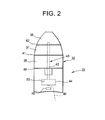
- the winglets 32 are capable of changing their configuration by morphing or transforming their shape, e.g., varying a trailing edge, rotation about an axis, elongation, camber change, boundary layer control, and altered geometry.
- a winglet 32 is illustratively shown with three adjustable portions 36 - 38 that are separated by joints 40 - 42.
- the winglet portions 36 - 38 may be composed of rigid material similar to the composition of the remainder of a blade 22.
- the winglet 32 is composed of a flexible material that is sufficiently pliable to allow for changing configuration of the winglet 32, whereby discrete portions are not necessary.
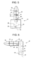
- FIG. 4 shows the winglet 32 configured at a sweep angle designated by line 52. While portions 36 - 38 are all positioned at the same sweep angle, each of the portions could be position at different sweep angles. The sweep can be forward or back and is useful in reducing drag.
- FIG. 5 shows the winglet 32 configured with a twist angle. The twist angle of the winglet 32 is out of the plane of the blade 22, as indicated by an arrow 33 (which is intended to show the winglet 32 twisting relative to the remainder of the blade 22 while continuing to be axially aligned therewith). While portions 36 - 38 are all positioned at the same twist angle, each of the portions could be position at different twist angles.
Landscapes
- Engineering & Computer Science (AREA)
- Life Sciences & Earth Sciences (AREA)
- Sustainable Development (AREA)
- Sustainable Energy (AREA)
- Chemical & Material Sciences (AREA)
- Combustion & Propulsion (AREA)
- Mechanical Engineering (AREA)
- General Engineering & Computer Science (AREA)
- Physics & Mathematics (AREA)
- Fluid Mechanics (AREA)
- Wind Motors (AREA)
Abstract
Description
- The subject matter described herein relates generally to wind turbines, and, more specifically, to wind turbine rotor blades having configurable winglets.
- A wind turbine typically has a tower supported at a base with a nacelle positioned at the upper end of the tower. At the nacelle a rotor hub is connected to a shaft and has a plurality of rotor blades mounted thereto. The shaft is rotated by the rotation of the rotor hub, which is itself rotated as a result of wind acting on the rotor blades. This rotational energy is communicated through a gearbox to a generator, which generates electricity.
- The rotor blades have a generally elongated airfoil shape with the outermost portions of the rotor blades being fixed in the same plane as the rest of the blades or positioned out of plane. The fixed turned portion is known as a winglet. Under certain operating conditions, this fixed winglet improves operating efficiency of the wind turbine when compared to rotor blades with the outermost portions thereof fixed in the same plane as the rest of the blade.
- According to one aspect of the invention, a rotor blade of a wind turbine has a winglet that is configurable in response to a sensed parameter.
- According to another aspect of the invention, a wind turbine includes a plurality of rotor blades for converting wind energy to rotational energy. The rotor blades have winglets that are configurable. The wind turbine includes a sensor for sensing a parameter and generating a sensed signal indicative of the parameter. The wind turbine further includes a processor receptive to the sensed signal for generating an actuator signal in response thereto. The wind turbine also includes an actuator associated with each of the winglets for configuring the winglets in response to the actuator signal.
- According to yet another aspect of the invention, a method of configuring a winglet of a rotor blade at a wind turbine includes sensing a parameter and configuring the winglet in response to the parameter.
- According to still another aspect of the invention, a method of configuring winglets of rotor blades at a wind turbine includes at low winds orienting the winglets in about the same plane as the rest of the respective rotor blades, and at high winds orienting the winglets away from the wind turbine, where the low winds have a wind speed that is less than a wind speed of the high winds.
- According to another aspect of the invention a method of configuring winglets of rotor blades at a wind turbine includes at low winds orienting each of the winglets towards the wind turbine, and at high winds orienting the winglets away from the wind turbine, where the low winds have a wind speed that is less than a wind speed of the high winds.
- These and other advantages and features will become more apparent from the following description taken in conjunction with the drawings.
- The subject matter, which is regarded as the invention, is particularly pointed out and distinctly claimed in the claims at the conclusion of the specification. The foregoing and other features, and advantages of the invention are apparent from the following detailed description taken in conjunction with the accompanying drawings in which:
-
FIG. 1 is a side elevation view of a wind turbine; -
FIG. 2 is a diagrammatic partial front elevation view of a rotor blade of the wind turbine with a winglet in a fully extended configuration; -
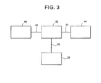
FIG. 3 is a schematic block diagram of the control system of the wind turbine; -
FIG. 4 is a diagrammatic partial front elevation view of a rotor blade of the wind turbine with the winglet in a configuration employing a sweep angle; -
FIG. 5 is a diagrammatic partial front elevation view of a rotor blade of the wind turbine with the winglet in a configuration employing a twist angle; -
FIG. 6 is a diagrammatic partial side elevation view of a rotor blade of the wind turbine with the winglet in a configuration employing a cant angle; -
FIG. 7 is a diagrammatic partial front elevation view of a rotor blade of the wind turbine with the winglet in a retracted configuration; -
FIG. 8 is a plurality of plots showing varied pitch angles of a blade having the winglet for Cp against TSR; -
FIG. 9 is a plot of the maximum Cp across the TSR domain obtained at different pitch angles as derived fromFIG. 8 ; -
FIG. 10 is a plurality of plots showing the maximum Cp across the TSR domain for a blade without a winglet, a blade with a fixed winglet, and a blade with the winglet of the invention; for tower strike constraint out-of-scope; -
FIG. 11 is a plurality of plots showing the maximum Cp across the TSR domain for a blade without a winglet, a blade with a fixed winglet, and a blade with the winglet of the invention; for tower strike constraint in-scope; and -
FIG. 12 is plurality of plots showing Cp, TSR, generator RPM, pitch, and power; all as a function of wind speed for a blade having the winglet of the invention. - The detailed description explains embodiments of the invention, together with advantages and features, by way of example with reference to the drawings.
- In general, a wind turbine includes a plurality of rotor blades for converting wind energy to rotational energy. Exemplary embodiments include the rotor blades having winglets that are configurable. The configuration of the winglets being selected to attain a desired performance of the wind turbine. The configuration of the winglets can be modified to maintain the desired performance in changing environmental and/or operating conditions. Also, the configuration of the winglets can be modified to attain a different desired performance of the wind turbine. Improved operation of the wind turbine can be achieved with configurable winglets.
- Referring to
FIG.1 , a wind turbine is shown generally at 10. Thewind turbine 10 has atower 12 supported at abase 14. Anacelle 16 is positioned at the upper end of thetower 12 with arotor hub shaft 18 extending therefrom. Arotor hub 20 is disposed at one end of theshaft 18 and has a plurality ofrotor blades 22 mounted thereto. Abrake 24 is provided on therotor hub shaft 18 to stop rotation of therotor blades 22 when desired. While thebrake 24 is shown at the low-speed shaft it is also know to locate the brake at the high-speed shaft. The other end of therotor hub shaft 18 interfaces with an input of agearbox 26. One end of agenerator shaft 28 interfaces with an output of thegearbox 26, which is configured to rotate thegenerator shaft 28 at a greater speed than that of therotor hub shaft 18 at the input. The other end of thegenerator shaft 28 drives agenerator 30, which is connected electrically (not shown) to atransformer 34. Alternatively, a direct dive wind turbine may be employed. - The
rotor blades 22 have a generally elongated airfoil shape to be efficiently driven by wind. When therotor blades 22 are rotated by the wind therotor hub shaft 18 will rotate therewith. Thegearbox 26 steps up this rotation speed to rotate thegenerator shaft 28 at a greater speed for driving thegenerator 30. Electrical power generated by thegenerator 30 is provided to thetransformer 34 for use in providing electric power. - An outermost portion of the
blades 22, referred to herein aswinglets 32, are capable of changing their configuration. Varied winglet configurations improve operating efficiency of thewind turbine 10. For example, improved energy capture in low winds and reduced noise operation in high winds are achievable. The configuration of thewinglets 32 affects the flow and aerodynamic forces on theblades 22. - Referring to
FIG. 2 , thewinglets 32 are capable of changing their configuration by morphing or transforming their shape, e.g., varying a trailing edge, rotation about an axis, elongation, camber change, boundary layer control, and altered geometry. Awinglet 32 is illustratively shown with three adjustable portions 36 - 38 that are separated by joints 40 - 42. The winglet portions 36 - 38 may be composed of rigid material similar to the composition of the remainder of ablade 22. Alternatively, thewinglet 32 is composed of a flexible material that is sufficiently pliable to allow for changing configuration of thewinglet 32, whereby discrete portions are not necessary. The winglet portions 36 - 38 are positioned in response to at least oneactuator 43 that includes at least oneactuator arm 45 driven by at least oneactuator driver 44. Theactuator 43 is powered by and is operated in response to electrical signals received at asignal line 46. Electrical power could be provided by thegenerator 30 and may need to be conditioned before being provided to theactuator 43. Theactuator 43 is an electric actuator, but could be pneumatic or otherwise. The at least oneactuator 43 can change height, sweep angle, cant angle, toe angle, twist angle, and/or radius of thewinglet 32 relative to theblade 22. - Alternatively, the
winglet 32 is comprised of a morphing material or another smart material in composite structures, such as a shape memory alloy or a shape memory polymer, wherein the configuration of thewinglet 32 can be changed when an actuation is applied to selected areas to achieve the desired configuration. Thewinglet 32 formed of a shape memory alloy such as a nickel-titanium alloy is initially deformed to be in an extended position. Upon application of heat by theactuator 43 at the particular transition temperature of the shape memory alloy, thewinglet 32 which is initially in a retracted (i.e., a non-deployed) position morphs to a deployed position. In addition to nickel-titanium alloy the shape memory alloy may be comprised of other alloys such as provided in the following Table:Alloy Composition Transformation Temperature Range °C. Transformation Hysteresis °C. AgCd 44∼49 at % Cd -190 ∼ -50 ∼ 15 AuCd 46.5 - 50 at % Cd 30 ∼ 100 ∼15 CuA1Ni 14 ∼ 14.5 Wt % A1 -140∼100 ∼ 35 3 - 4.5 Wt % Ni CuSn ∼15 at % 5n -120 ∼ 30 CuZn 38.5 ∼ 41.5 Wt % Zn -180∼-10 ∼10 CuZn X few Wt % X -180∼200 ∼ 10 (X = Si Sn A1) InTi 18-23 at % T1 60 ∼ 100 ∼4 NiAl 36 ∼ 38 at % A1 -180 ∼ 100 ∼10 NiTi 49∼51 at % Ni -50∼110 -30 FePt ∼ 25 at % Pt ∼-130 ∼4 MnCu 5∼35at % Cu -250∼180 -25 FeMnSi 32 Wt % Mn -200 ∼150 ∼100 Fe--Cr--Ni--Co--Mn—Si ,- -- -100∼300 ∼ 50 Fe--Cr--Ni--Mn--Si ,- -- -100 ∼ 300 ∼ 50 - It will also be appreciated that other types of electromechanical actuation may be used.
- Shape memory polymers may also be used; they are polymeric smart materials that have the ability to return from a deformed state to their original shape induced by an external stimulus or trigger, such as temperature change. In addition to temperature change, the shape memory effect of shape memory polymers can also be triggered by an electric or magnetic field, light or a change in pH. As with polymers in general, shape memory polymers also cover a wide property-range from stable to biodegradable, from soft to hard, and from elastic to rigid, depending on the structural units that constitute the shape memory polymer. Shape memory polymers include thermoplastic and thermoset (i.e., covalently cross-linked) polymeric materials. Shape memory polymers are presently able to store up to three different shapes in memory. Suitable polymeric materials are provided in the Table below.
Hard Phase Crosslinker Tr(°C) Rf(5)(%) Rf(5)(%) PET Glycerol/dimethyl5- sulfoisopthalate 11-30 90-95 60-70 PET Malcic anhydride 8-13 91-93 60 AA/MMA copolymer N,N'-methylene-bis- acrylamide 90 -- 99 MMA/N-vinyl-2 pyrrolidone Ethyleneglycol 90 -- 99 Dimethacrylate PMMA/N-vinyl-2- pyrrolidone Ethyleneglycol 45,100 -- 99 Dimethacrylate - The use of shape memory polymer or shape memory alloy depends on the specific application, as they differ by their glass transition or melting transition from a hard to a soft phase, which is responsible for the shape memory effect. In shape memory alloys Martensitic/Austenitic transitions are responsible for the shape memory effect. In most applications shape memory polymers are desired over shape memory alloys as they have a high capacity for elastic deformation (e.g., up to 200%), lower cost, lower density, a broad range of application temperatures which can be tailored, easy processing, and potential biocompatibility and biodegradability.
- Referring also to
FIG. 3 , the desired configuration of thewinglet 32 is calculated in response to sensed parameters, such as wind speed, acoustic, load, acceleration, rotor speed (RPM), rotor torque, generator speed (RPM), and/or generator torque. Asensor 48 is located depending upon the variable being sensed. For example, acoustics, loads, and acceleration may be better sensed by sensors at theblade 22. Wind speed could be sensed elsewhere at thewind turbine 10 or even remote therefrom. Sensed signals from thesensors 48 are transmitted, via thesignal line 46 or otherwise (e.g., wirelessly or another signal line), to aprocessor 50 associated with theactuator diver 44. Theprocessor 50 processes this information to determine the desired configuration of thewinglet 32 and communicates the proper electrical signals via asignal line 51 to theactuator driver 44 for configuring thewinglet 32. While real-time configuring of thewinglet 32 is anticipated, certain conditions may require that the rotation of theblades 22 be stopped or slowed until thewinglets 32 are reconfigured (such as in high wind conditions), whereby theprocessor 50 would communicate a signal to apply thebrake 24, via asignal line 53. - Several exemplary configurations are illustrated in
FIGs. 4 - 7 .FIG. 4 shows thewinglet 32 configured at a sweep angle designated byline 52. While portions 36 - 38 are all positioned at the same sweep angle, each of the portions could be position at different sweep angles. The sweep can be forward or back and is useful in reducing drag.FIG. 5 shows thewinglet 32 configured with a twist angle. The twist angle of thewinglet 32 is out of the plane of theblade 22, as indicated by an arrow 33 (which is intended to show thewinglet 32 twisting relative to the remainder of theblade 22 while continuing to be axially aligned therewith). While portions 36 - 38 are all positioned at the same twist angle, each of the portions could be position at different twist angles. The twist angle of thewinglet 32 reduces an angle of incidence, and therefore causes a lower angle of attack.FIG. 6 shows thewinglet 32 configured at a cant angle designated 56. While portions 36 - 38 are all positioned at the same cant angle, each of the portions could be positioned at different cant angles. The cant angle of thewinglet 32 is about the plane of theblade 22. Cant angles in this example are adjustable between 0 and 90 degree. The cant angle of the winglet and the size and shape of the winglet, are critical for performance. For example, the curvature radius between thewinglet 32 and the remainder of theblade 22 can impact efficiency. The cantedwinglets 32 decrease the tip vortex, which is created by the pressure difference on the suction side of theblade 22 that accelerates the flow at the tip of theblade 22 in direction perpendicular thereto. Thusly decreasing downwash on the center of theblade 22 where the aerodynamic forces are large.FIG. 7 shows thewinglet 32 configured at a reduced height or length. The portions 36 - 38 are shown as a telescoping mechanism allowing various lengths to be configured. Other configurations can be obtained as required, including changing the overall shape of thewinglet 32. Further any combinations of configurations can be employed. - By way of example the twist angle discussed with reference to
FIG. 5 , may be accomplished using a longitudinal spar as theactuator arm 45 extending from within theblade 22 to thewinglet 32. Theactuator driver 44 comprises a torsionally flexible passive torque tube of shape memory alloy, which is connected to theblade spar 45 near thewinglet 32 and at least one thermoelectric device that activates the shape memory alloy by applying heat, which causes the torque tube to twist under the induced torque. This twisting causes thelongitudinal spar 45 to rotate, which causes thewinglet 32 to twist to a desired position. Thewinglet 32 can be returned to its original (or non-activated) position by removing the heat, which can be accomplished by deactivation of the thermoelectric device and application of a heat sink to draw the heat away from the shape memory alloy. The heat sink, while not shown, may be internal or external to theblade 22. - Referring to
FIG. 8 , plots 60 - 62 show varied pitch angles of theblade 22 having thewinglet 32 for Cp (a ratio of power from thewind turbine 10 and power available from the wind) against TSR (tip speed ratio, a ratio of rotational speed at the tip of theblade 22 and the actual speed of the wind).Points 64 indicate the maximum Cp across the TSR domain, wherein the maximum Cp is obtained at different pitch angles. Accordingly, improved results can be achieved with a varied pitch angle rather than a fixed angle. Referring also toFIG. 9 , aplot 66 of the maximum Cp across the TSR domain obtained at different pitch angles as derived fromFIG. 8 is shown. - Referring to
FIG. 10 , aplot 68 shows the maximum Cp across the TSR domain for a blade without a winglet (not shown), aplot 70 shows the maximum Cp across the TSR domain for a blade with a fixed winglet (not shown), andplot 72 shows the maximum Cp across the TSR domain for theblade 22 having thewinglet 32. Theplots winglet 32 is to be oriented upstream on the pressure side, i.e., away from thetower 12, in the presence of high winds. Theplot 72 for thewinglet 32 provides the greatest maximum Cp across the TSR domain, as compared toplots FIG. 11 , aplot 74 shows the maximum Cp across the TSR domain for a blade without a winglet (not shown), aplot 76 shows the maximum Cp across the TSR domain for a blade with a fixed winglet (not shown), andplot 78 shows the maximum Cp across the TSR domain forblade 22 having thewinglet 32. Theplots winglet 32 is to be oriented downstream on the suction side, i.e., towards thetower 12, in the presence of low winds. Orienting thewinglet 32 downstream on the suction side is generally more efficient than orienting thewinglet 32 upstream on the pressure side. As in above example (FIG. 10 ), theplot 78 for thewinglet 32 also provides the greatest maximum Cp across the TSR domain, as compared toplots winglet 32 with tower strike in-scope is allowed to deflect from downstream on the suction side to upstream on the pressure side in high winds, to avoid tower strike. This deflection enables larger, therefore more efficient, operation of thewinglet 32 downstream on suction side in low winds. During typical operation, thewinglets 32 are rotated from downstream on the suction side in low winds to upstream on the pressure side as the wind changes to high winds, and vices versa. The winglets can be configured to be partially or fully (i.e., generally perpendicular) downstream and/or upstream. - Alternatively, at low winds the
winglet 32 is oriented in the same plane as the rest of theblade 22 to capture more kinetic energy from the wind resulting in higher torque. At high winds thewinglet 32 is oriented away from the tower 12 (referred to above as out-of-scope) to reduce the intensity of wingtip vortices, the resultant induced drag, and the vortex shedding induced noise. At low winds the strength of the wing tip vortex is low. The effect of this low strength wing tip vortex on the performance of thewind turbine 10 is insignificant. Accordingly, at low winds thewinglets 32 that serve to arrest the wing tip vortex, may not significantly improve overall performance. Further, the additional drag of thewinglets 32 may diminish the torque generated. At low winds for thewinglets 32 oriented in the same plane as the rest of therespective blades 22 the ratio is 1, and for thewinglets 32 oriented away from thetower 12 the ratio is 0.5. At low winds forwinglets 32 oriented away from thetower 12, the increment in drag is significantly higher than the power increment. At low winds for thewinglets 32 oriented in the same plane as the rest of therespective blades 22, the swept area is higher and more torque is generated. This higher torque assists in bringing down the cut-in speed, which is the speed of free stream wind at which thewind turbine 10 starts producing power, and increases the overall energy yield of thewind turbine 10. At high winds, the aerodynamic loading on theblades 22 is high and results in a strong wind tip vortex. Depending upon the free stream wind condition thewinglets 32 can be partially or fully (i.e., generally perpendicular) oriented away from thetower 20 for power control. At high winds, for thewinglets 32 oriented in the same plane as the rest of therespective blades 22 the ratio is 1, and for thewinglets 32 oriented away from thetower 12 the ratio is 0.9. Even though thewinglets 32 orientated away from thetower 12 have slightly lesser benefit than thewinglets 32 oriented in the same plane as the rest of therespective blades 22, it has other benefits such as noise reduction and reduced wake width. During operation, thewinglets 32 are rotated from the same plane as the rest of theblade 22 in low winds to away from thetower 12 as the wind changes to high winds, and vice-versa. - The low winds simply have a wind speed that is less than a wind speed of the high winds. A specific wind speed is not intended by low winds or high winds. What would be considered low winds and high winds is determined by the type and size (capacity) of the wind turbine, and what parameter or parameters the wind turbine is being managed to meet. Accordingly, the wind speeds at which the orientation of the
winglets 32 is changed will be dictated by desired performance parameters of a specific wind turbine. What might be considered high winds in one application, such as acoustic noise reduction, could be considered low winds in another application, such as improving power generation of the wind turbine. Again, neither a specific wind speed nor range of wind speeds is intended by low winds and/or high winds. Referring toFIG. 12 , aplot 80 shows Cp as a function of wind speed, aplot 82 shows TSR as a function wind speed, aplot 84 shows generator RPM as a function of wind speed, aplot 86 shows pitch as a function of wind speed, and a plot 88 shows power as a function of wind speed; for theblade 22 having thewinglet 32.Regions region 92 is at a variable speed. From analysis of aregion 96 it is appreciated that thewinglet 32 allows for higher Cp for operating conditions outside of a design point, with no tower strike limits. Theregion 96 coincides with theregion 90 for constant speed. From analysis of aregion 98 it is appreciated that due to tower strike mitigation theblades 22 do not experience tower closeness, in other words, tower strike is not a concern. Thusly, allowing thewinglet 32 to be rotated downstream on the suction side taking advantage of more efficient operation. This portion ofconstant TSR plot 82 andconstant pitch plot 86, i.e.,region 98, is the design point. Theregion 98 coincides with theregion 92 for variable speed. From analysis of aregion 100 it is appreciated that thewinglet 32 allows for higher Cp for operating conditions outside of the design point, with tower strike limited. It will be appreciated that withinregions blade 22 having thewinglet 32 than with a blade having a fixed winglet or no winglet at all. From analysis of aregion 102 it is appreciated that thewinglet 32 has the potential to yield the same power (as power is constant in this region) at a lower load or thrust. Theregion 102 coincides with theregion 94 for constant speed. - While the invention has been described in detail in connection with only a limited number of embodiments, it should be readily understood that the invention is not limited to such disclosed embodiments. Rather, the invention can be modified to incorporate any number of variations, alterations, substitutions or equivalent arrangements not heretofore described, but which are commensurate with the spirit and scope of the invention. Additionally, while various embodiments of the invention have been described, it is to be understood that aspects of the invention may include only some of the described embodiments. Accordingly, the invention is not to be seen as limited by the foregoing description, but is only limited by the scope of the appended claims.
- Various aspects and embodiments of the present invention are defined by the following numbered clauses:
- 1. A rotor blade of a wind turbine, comprising the rotor blade having a winglet that is configurable in response to a sensed parameter.
- 2. The rotor blade of
clause 1 wherein the winglet is configurable as having at least one of a variable sweep angle, a variable twist angle, a variable cant angle, a variable length, a variable toe angle, and a variable radius. - 3. The rotor blade of any preceding clause wherein the sensed parameter comprises at least one of wind speed, acoustic, load, acceleration, rotor speed, rotor torque, generator speed, and generator torque.
- 4. The rotor blade of any preceding clause wherein the winglet is configurable by morphing.
- 5. The rotor blade of any preceding clause the morphing comprises at least one of varying a trailing edge, rotating about an axis, elongating, changing camber, controlling a boundary layer, and altering geometry.
- 6. The rotor blade of any preceding clause wherein the winglet comprises a shape memory polymer or shape memory alloy.
- 7. The rotor blade of any preceding clause wherein the winglet comprises a smart material in a composite structure.
- 8. A wind turbine, comprising:
- a plurality of rotor blades for converting wind energy to rotational energy, the rotor blades having winglets that are configurable;
- a sensor for sensing a parameter and generating a sensed signal indicative of the parameter;
- a processor receptive to the sensed signal for generating an actuator signal in response thereto; and
- an actuator associated with each of the winglets for configuring the winglets in response to the actuator signal.
- 9. The wind turbine of any preceding clause wherein the winglets are configurable as having at least one of a variable sweep angle, a variable twist angle, a variable cant angle, a variable length, a variable toe angle, and a variable radius.
- 10. The wind turbine of any preceding clause wherein the sensor comprises at least one of a wind speed sensor, an acoustic sensor, a load sensor, an acceleration sensor, a rotor speed sensor, a rotor torque sensor, a generator speed sensor, and a generator torque sensor.
- 11. The wind turbine of any preceding clause wherein the winglets are configurable by morphing.
- 12. The wind turbine of any preceding clause the morphing comprises at least one of varying a trailing edge of the winglets, rotating the winglets about an axis, elongating the winglets, changing camber of the winglets, controlling a boundary layer of the winglets, and altering geometry of the winglets.
- 13. The wind turbine of any preceding clause wherein the winglets comprises a shape memory polymer or shape memory alloy.
- 14. The wind turbine of any preceding clause wherein the winglets comprises a smart material in a composite structure.
- 15. The wind turbine of any preceding clause wherein the actuators comprise electric actuators.
- 16. A method of configuring a winglet of a rotor blade at a wind turbine, comprising:
- sensing a parameter; and
- configuring the winglet in response to the parameter.
- 17. The method of any preceding clause wherein the configuring the winglet comprises configuring at least one of a variable sweep angle, a variable twist angle, a variable cant angle, a variable length, a variable toe angle, and a variable radius, of the winglet.
- 18. The method of any preceding clause wherein the parameter comprises at least one of wind speed, acoustic, load, acceleration, rotor speed, rotor torque, generator speed, and generator torque.
- 19. The method of any preceding clause wherein the winglet is configurable by morphing.
- 20. The method of any preceding clause wherein the morphing comprises at least one of varying a trailing edge, rotating about an axis, elongating, changing camber, controlling a boundary layer, and altering geometry.
- 21. The method of any preceding clause wherein the configuring the winglet comprises:
- at low winds configuring the winglet in about the same plane as the rest of the rotor blade; and
- at high winds configuring the winglet away from the wind turbine, where the low winds have a wind speed that is less than a wind speed of the high winds.
- 22. The method of any preceding clause wherein the configuring the winglet comprises:
- at low winds configuring the winglet towards the wind turbine; and
- at high winds configuring the winglet away from the wind turbine, where the low winds have a wind speed that is less than a wind speed of the high winds.
- 23. A method of configuring winglets of rotor blades at a wind turbine, comprising:
- at low winds orienting the winglets in about the same plane as the rest of the respective rotor blades; and
- at high winds orienting the winglets away from the wind turbine, where the low winds have a wind speed that is less than a wind speed of the high winds.
- 24. The method of any preceding clause wherein the orienting the winglets away from the wind turbine comprises orienting the winglets partially away from the wind turbine.
- 25. The method of any preceding clause wherein the orienting the winglets away from the wind turbine comprises orienting the winglets fully away from the wind turbine.
- 26. A method of configuring winglets of rotor blades at a wind turbine, comprising:
- at low winds orienting the winglets towards the wind turbine; and
- at high winds orienting the winglets away from the wind turbine, where the low winds have a wind speed that is less than a wind speed of the high winds.
- 27. The method of any preceding clause wherein the orienting the winglets towards the wind turbine comprises orienting the winglets partially towards the wind turbine.
- 28. The method of any preceding clause wherein the orienting the winglets away from the wind turbine comprises orienting the winglets partially away from the wind turbine.
- 29. The method of any preceding clause wherein the orienting the winglets towards the wind turbine comprises orienting the winglets fully towards the wind turbine.
- 30. The method of any preceding clause wherein the orienting the winglets away from the wind turbine comprises orienting the winglets fully away from the wind turbine.
Claims (8)
- A wind turbine (10), comprising:a plurality of rotor blades (22) for converting wind energy to rotational energy, the rotor blades (22) having winglets (32) that are configurable;a sensor (48) for sensing a parameter and generating a sensed signal indicative of the parameter;a processor (50) receptive to the sensed signal for generating an actuator signal in response thereto; andan actuator (43) associated with each of the winglets (32) for configuring the winglets (32) in response to the actuator signal.
- The wind turbine (10) of claim 1 wherein the winglets (32) are configurable as having at least one of a variable sweep angle, a variable twist angle, a variable cant angle, a variable length, a variable toe angle, and a variable radius.
- The wind turbine (10) of any preceding claim wherein the sensor (48) comprises at least one of a wind speed sensor, an acoustic sensor, a load sensor, an acceleration sensor, a rotor speed sensor, a rotor torque sensor, a generator speed sensor, and a generator torque sensor.
- The wind turbine (10) of any preceding claim wherein the winglets (32) are configurable by morphing.
- The wind turbine (10) of claim 4 the morphing comprises at least one of varying a trailing edge of the winglets (32), rotating the winglets (32) about an axis, elongating the winglets (32), changing camber of the winglets (32), controlling a boundary layer of the winglets (32), and altering geometry of the winglets (32).
- The wind turbine (10) of any preceding claim wherein the winglets (32) comprises a shape memory polymer or shape memory alloy.
- The wind turbine (10) of any preceding claim wherein the winglets (32) comprises a smart material in a composite structure.
- The wind turbine (10) of any preceding claim wherein the actuators (43) comprise electric actuators.
Applications Claiming Priority (1)
| Application Number | Priority Date | Filing Date | Title |
|---|---|---|---|
| US12/761,150 US20110255974A1 (en) | 2010-04-15 | 2010-04-15 | Configurable winglet for wind turbine blades |
Publications (2)
| Publication Number | Publication Date |
|---|---|
| EP2378115A2 true EP2378115A2 (en) | 2011-10-19 |
| EP2378115A3 EP2378115A3 (en) | 2014-05-14 |
Family
ID=44063760
Family Applications (1)
| Application Number | Title | Priority Date | Filing Date |
|---|---|---|---|
| EP11161814.6A Withdrawn EP2378115A3 (en) | 2010-04-15 | 2011-04-11 | Configurable winglet for wind turbine blades |
Country Status (3)
| Country | Link |
|---|---|
| US (1) | US20110255974A1 (en) |
| EP (1) | EP2378115A3 (en) |
| CN (1) | CN102220935A (en) |
Cited By (7)
| Publication number | Priority date | Publication date | Assignee | Title |
|---|---|---|---|---|
| WO2013092871A1 (en) | 2011-12-22 | 2013-06-27 | Lm Wind Power A/S | Wind turbine blade assembled from inboard part and outboard part having different types of load carrying structures |
| WO2013142411A1 (en) * | 2012-03-20 | 2013-09-26 | General Electric Company | Winglet for a wind turbine rotor blade |
| WO2016167754A1 (en) * | 2015-04-15 | 2016-10-20 | General Electric Company | System for wind turbine blade actuation |
| CN108331712A (en) * | 2018-02-27 | 2018-07-27 | 青岛华创风能有限公司 | It is a kind of can noise reducing wind electricity blade |
| CN110089021A (en) * | 2016-09-14 | 2019-08-02 | 智能合金有限公司 | Shape memory alloy actuator with strain gage sensor and position estimation and method of making the same |
| CN114313215A (en) * | 2022-01-28 | 2022-04-12 | 天津大学 | Wing tip structure with variable inclination angle and height |
| CN116374169A (en) * | 2023-05-05 | 2023-07-04 | 南京航空航天大学 | Method, system and device for controlling rotor blades of a variable-sweep wing |
Families Citing this family (21)
| Publication number | Priority date | Publication date | Assignee | Title |
|---|---|---|---|---|
| WO2011067290A1 (en) * | 2009-12-01 | 2011-06-09 | Vestas Wind Systems A/S | A wind turbine nacelle comprising a heat exchanger assembly |
| EP2365215B1 (en) * | 2010-03-10 | 2012-12-12 | Siemens Aktiengesellschaft | Rotational speed control of a wind turbine based on rotor acceleration |
| GB2485340A (en) * | 2010-11-02 | 2012-05-16 | Vestas Wind Sys As | A wind turbine comprising rotor and tower bending sensors |
| US9709029B2 (en) * | 2011-06-21 | 2017-07-18 | University Of Virginia Patent Foundation | Morphing segmented wind turbine and related method |
| GB2493166A (en) * | 2011-07-26 | 2013-01-30 | Khalil Abu Al-Rubb | Sail-type turbine blade with buoyant structure, adjustable tip, flexible reinforcement, tip cap and uncovered non-working parts |
| EP2597329A1 (en) * | 2011-11-23 | 2013-05-29 | Siemens Aktiengesellschaft | Braking system for a wind turbine |
| US10661885B2 (en) * | 2012-05-16 | 2020-05-26 | The Boeing Company | Shape memory alloy active spars for blade twist |
| CN102808727A (en) * | 2012-08-12 | 2012-12-05 | 浙江海洋学院 | Manufacturing method of fan noise reducing soft paddle |
| CN102996367A (en) * | 2012-11-29 | 2013-03-27 | 南京航空航天大学 | Movable winglet device for wind turbine blade |
| US9366224B2 (en) | 2013-06-27 | 2016-06-14 | General Electric Company | Wind turbine blade and method of fabricating the same |
| WO2016148015A1 (en) * | 2015-03-16 | 2016-09-22 | Ntn株式会社 | Turbine rotor and natural energy generating device equipped with same |
| CN105416538B (en) * | 2015-12-07 | 2017-10-03 | 哈尔滨工业大学 | The marine propeller of deformable blade |
| US10626846B2 (en) * | 2016-11-17 | 2020-04-21 | General Electric Company | System for wind turbine blade actuation |
| CN108266313A (en) * | 2018-02-27 | 2018-07-10 | 青岛华创风能有限公司 | A kind of low pneumatic noise Wind turbines |
| WO2020025093A1 (en) * | 2018-08-01 | 2020-02-06 | Vestas Wind Systems A/S | Noise reduction in a wind turbine with hinged blades |
| US11118567B2 (en) * | 2019-06-26 | 2021-09-14 | General Electric Company | Systems and methods for pitching of rotor blades |
| US11486349B2 (en) | 2020-01-10 | 2022-11-01 | General Electric Company | Methods for manufacturing blade structures |
| CN112682334A (en) * | 2020-12-11 | 2021-04-20 | 浙江工业大学 | Reversible fan based on bistable-state blades and manufacturing method |
| US20250376970A1 (en) * | 2022-06-22 | 2025-12-11 | Vestas Wind Systems A/S | A family of wind turbine blades |
| US11988187B1 (en) | 2023-07-13 | 2024-05-21 | United Arab Emirates University | Wind turbine blade with self-adaptive tip-sweep |
| CN119957429A (en) * | 2024-12-27 | 2025-05-09 | 中国华能集团清洁能源技术研究院有限公司 | Wind power generation equipment |
Family Cites Families (13)
| Publication number | Priority date | Publication date | Assignee | Title |
|---|---|---|---|---|
| US3038543A (en) * | 1960-10-03 | 1962-06-12 | Hudson Engineering Corp | Air brake for wind driven propellers |
| US4355955A (en) * | 1981-04-06 | 1982-10-26 | The Boeing Company | Wind turbine rotor speed control system |
| JP2003278642A (en) * | 2002-03-22 | 2003-10-02 | Kazumi Osada | Wind power generation device |
| DE10300284A1 (en) * | 2003-01-02 | 2004-07-15 | Aloys Wobben | Turbine rotor blade for wind-powered energy plant has tip region curved or angled in direction of rotor blade trailing edge |
| MXPA05007120A (en) * | 2003-01-02 | 2005-09-21 | Wobben Aloys | Rotor blade for a wind power plant. |
| EP1603798B1 (en) * | 2003-03-03 | 2010-10-20 | Flexsys, Inc. | Adaptive compliant wing and rotor system |
| WO2004088130A1 (en) * | 2003-03-31 | 2004-10-14 | Forskningscenter Risø | Control of power, loads and/or stability of a horizontal axis wind turbine by use of variable blade geometry control |
| WO2005017351A1 (en) * | 2003-07-29 | 2005-02-24 | General Electric Company | Variable diameter rotor |
| US8419362B2 (en) * | 2004-08-31 | 2013-04-16 | Hamilton Sundstrand Corporation | Foldable blades for wind turbines |
| DE102005028688A1 (en) * | 2005-05-19 | 2006-11-30 | Airbus Deutschland Gmbh | Wing unit`s aerodynamic characteristics adapting device for e.g. aircraft, has winglet rotatable in relation to wing unit, such that angle between rotary axis and main direction of extension of unit differs from specified degree |
| DK200500899A (en) * | 2005-06-17 | 2006-12-18 | Lm Glasfiber As | Wing with hinged wing tip |
| AU2007336537B2 (en) * | 2006-12-22 | 2011-05-26 | Vestas Wind Systems A/S | Wind turbine with rotor blades equipped with winglets and blades for such rotor |
| DE102007041649A1 (en) * | 2007-09-03 | 2009-03-05 | Daubner & Stommel GbR Bau-Werk-Planung (vertretungsberechtigter Gesellschafter: Matthias Stommel, 27777 Ganderkesee) | Rotor blade, wind energy plant and method for operating a wind turbine |
-
2010
- 2010-04-15 US US12/761,150 patent/US20110255974A1/en not_active Abandoned
-
2011
- 2011-04-11 EP EP11161814.6A patent/EP2378115A3/en not_active Withdrawn
- 2011-04-15 CN CN2011101045114A patent/CN102220935A/en active Pending
Non-Patent Citations (1)
| Title |
|---|
| None |
Cited By (12)
| Publication number | Priority date | Publication date | Assignee | Title |
|---|---|---|---|---|
| WO2013092871A1 (en) | 2011-12-22 | 2013-06-27 | Lm Wind Power A/S | Wind turbine blade assembled from inboard part and outboard part having different types of load carrying structures |
| US10253751B2 (en) | 2011-12-22 | 2019-04-09 | LM WP Patent Holdings A/S | Wind turbine blade assembled from inboard part and outboard part having different types of load carrying structures |
| WO2013142411A1 (en) * | 2012-03-20 | 2013-09-26 | General Electric Company | Winglet for a wind turbine rotor blade |
| US9103325B2 (en) | 2012-03-20 | 2015-08-11 | General Electric Company | Winglet for a wind turbine rotor blade |
| US10047719B2 (en) | 2012-03-20 | 2018-08-14 | General Electric Company | Winglet for a wind turbine rotor blade |
| EP2828521B1 (en) | 2012-03-20 | 2019-02-27 | General Electric Company | Winglet for a wind turbine rotor blade |
| WO2016167754A1 (en) * | 2015-04-15 | 2016-10-20 | General Electric Company | System for wind turbine blade actuation |
| CN110089021A (en) * | 2016-09-14 | 2019-08-02 | 智能合金有限公司 | Shape memory alloy actuator with strain gage sensor and position estimation and method of making the same |
| CN108331712A (en) * | 2018-02-27 | 2018-07-27 | 青岛华创风能有限公司 | It is a kind of can noise reducing wind electricity blade |
| CN114313215A (en) * | 2022-01-28 | 2022-04-12 | 天津大学 | Wing tip structure with variable inclination angle and height |
| CN114313215B (en) * | 2022-01-28 | 2023-11-14 | 天津大学 | A wing tip structure with variable inclination and height |
| CN116374169A (en) * | 2023-05-05 | 2023-07-04 | 南京航空航天大学 | Method, system and device for controlling rotor blades of a variable-sweep wing |
Also Published As
| Publication number | Publication date |
|---|---|
| CN102220935A (en) | 2011-10-19 |
| US20110255974A1 (en) | 2011-10-20 |
| EP2378115A3 (en) | 2014-05-14 |
Similar Documents
| Publication | Publication Date | Title |
|---|---|---|
| US20110255974A1 (en) | Configurable winglet for wind turbine blades | |
| EP2425129B1 (en) | Wind turbine rotor blade | |
| EP1805412B1 (en) | Turbine and compressor employing tubercle leading edge rotor design | |
| US20120027595A1 (en) | Pitchable winglet for a wind turbine rotor blade | |
| EP1995455B1 (en) | Actuation system for a wind turbine blade flap | |
| EP2466121A2 (en) | Wind turbine, aerodynamic assembly for use in a wind turbine, and method for assembling thereof | |
| EP2019203B1 (en) | Wind turbine blade with cambering flaps | |
| US8616846B2 (en) | Aperture control system for use with a flow control system | |
| EP2341245B1 (en) | Apparatus for increasing lift on wind turbine blade | |
| EP2267298A2 (en) | Wind turbine blade with rotatable fins at the tip | |
| EP2587051A2 (en) | Vertical axis wind turbines | |
| EP2098721A2 (en) | A wind turbine blade | |
| EP2141355A2 (en) | Wind turbine blades with multiple curvatures | |
| EP2085609A1 (en) | Wind turbine blade with cambering flaps controlled by surface pressure changes | |
| CA2710524C (en) | Wind turbine blade and assembly | |
| GB2464163A (en) | Variable leading edge wind turbine blade | |
| CN101198788A (en) | Blades with hinged tips | |
| WO2013052761A1 (en) | Wind turbine having flow-aligned blades | |
| US8851857B2 (en) | Wind turbine blade and wind power generator using the same | |
| EP2778400B1 (en) | Actuation of load management devices on aerodynamic blades | |
| EP2778398A2 (en) | Failsafe deployment system for wind turbine blade air deflector | |
| US10422318B2 (en) | Wind turbine blade | |
| JP4533991B1 (en) | Small propeller windmill | |
| WO2025217084A1 (en) | Passive trailing edge including chord extensions | |
| WO2024209197A1 (en) | Turbine blade |
Legal Events
| Date | Code | Title | Description |
|---|---|---|---|
| AK | Designated contracting states |
Kind code of ref document: A2 Designated state(s): AL AT BE BG CH CY CZ DE DK EE ES FI FR GB GR HR HU IE IS IT LI LT LU LV MC MK MT NL NO PL PT RO RS SE SI SK SM TR |
|
| AX | Request for extension of the european patent |
Extension state: BA ME |
|
| PUAI | Public reference made under article 153(3) epc to a published international application that has entered the european phase |
Free format text: ORIGINAL CODE: 0009012 |
|
| PUAL | Search report despatched |
Free format text: ORIGINAL CODE: 0009013 |
|
| AK | Designated contracting states |
Kind code of ref document: A3 Designated state(s): AL AT BE BG CH CY CZ DE DK EE ES FI FR GB GR HR HU IE IS IT LI LT LU LV MC MK MT NL NO PL PT RO RS SE SI SK SM TR |
|
| AX | Request for extension of the european patent |
Extension state: BA ME |
|
| RIC1 | Information provided on ipc code assigned before grant |
Ipc: F03D 7/04 20060101AFI20140409BHEP Ipc: F03D 1/06 20060101ALI20140409BHEP Ipc: F03D 7/02 20060101ALI20140409BHEP |
|
| STAA | Information on the status of an ep patent application or granted ep patent |
Free format text: STATUS: THE APPLICATION IS DEEMED TO BE WITHDRAWN |
|
| 18D | Application deemed to be withdrawn |
Effective date: 20141101 |
|
| P01 | Opt-out of the competence of the unified patent court (upc) registered |
Effective date: 20230522 |