EP2378092B1 - Vorkühler - Google Patents
Vorkühler Download PDFInfo
- Publication number
- EP2378092B1 EP2378092B1 EP11159341.4A EP11159341A EP2378092B1 EP 2378092 B1 EP2378092 B1 EP 2378092B1 EP 11159341 A EP11159341 A EP 11159341A EP 2378092 B1 EP2378092 B1 EP 2378092B1
- Authority
- EP
- European Patent Office
- Prior art keywords
- flange
- coolant
- cooler
- housing
- exhaust
- Prior art date
- Legal status (The legal status is an assumption and is not a legal conclusion. Google has not performed a legal analysis and makes no representation as to the accuracy of the status listed.)
- Not-in-force
Links
Images
Classifications
-
- F—MECHANICAL ENGINEERING; LIGHTING; HEATING; WEAPONS; BLASTING
- F01—MACHINES OR ENGINES IN GENERAL; ENGINE PLANTS IN GENERAL; STEAM ENGINES
- F01N—GAS-FLOW SILENCERS OR EXHAUST APPARATUS FOR MACHINES OR ENGINES IN GENERAL; GAS-FLOW SILENCERS OR EXHAUST APPARATUS FOR INTERNAL-COMBUSTION ENGINES
- F01N3/00—Exhaust or silencing apparatus having means for purifying, rendering innocuous, or otherwise treating exhaust
- F01N3/02—Exhaust or silencing apparatus having means for purifying, rendering innocuous, or otherwise treating exhaust for cooling, or for removing solid constituents of, exhaust
- F01N3/04—Exhaust or silencing apparatus having means for purifying, rendering innocuous, or otherwise treating exhaust for cooling, or for removing solid constituents of, exhaust using liquids
- F01N3/043—Exhaust or silencing apparatus having means for purifying, rendering innocuous, or otherwise treating exhaust for cooling, or for removing solid constituents of, exhaust using liquids without contact between liquid and exhaust gases
-
- F—MECHANICAL ENGINEERING; LIGHTING; HEATING; WEAPONS; BLASTING
- F01—MACHINES OR ENGINES IN GENERAL; ENGINE PLANTS IN GENERAL; STEAM ENGINES
- F01N—GAS-FLOW SILENCERS OR EXHAUST APPARATUS FOR MACHINES OR ENGINES IN GENERAL; GAS-FLOW SILENCERS OR EXHAUST APPARATUS FOR INTERNAL-COMBUSTION ENGINES
- F01N13/00—Exhaust or silencing apparatus characterised by constructional features
- F01N13/08—Other arrangements or adaptations of exhaust conduits
-
- F—MECHANICAL ENGINEERING; LIGHTING; HEATING; WEAPONS; BLASTING
- F01—MACHINES OR ENGINES IN GENERAL; ENGINE PLANTS IN GENERAL; STEAM ENGINES
- F01N—GAS-FLOW SILENCERS OR EXHAUST APPARATUS FOR MACHINES OR ENGINES IN GENERAL; GAS-FLOW SILENCERS OR EXHAUST APPARATUS FOR INTERNAL-COMBUSTION ENGINES
- F01N3/00—Exhaust or silencing apparatus having means for purifying, rendering innocuous, or otherwise treating exhaust
- F01N3/02—Exhaust or silencing apparatus having means for purifying, rendering innocuous, or otherwise treating exhaust for cooling, or for removing solid constituents of, exhaust
- F01N3/04—Exhaust or silencing apparatus having means for purifying, rendering innocuous, or otherwise treating exhaust for cooling, or for removing solid constituents of, exhaust using liquids
- F01N3/043—Exhaust or silencing apparatus having means for purifying, rendering innocuous, or otherwise treating exhaust for cooling, or for removing solid constituents of, exhaust using liquids without contact between liquid and exhaust gases
- F01N3/046—Exhaust manifolds with cooling jacket
-
- F—MECHANICAL ENGINEERING; LIGHTING; HEATING; WEAPONS; BLASTING
- F01—MACHINES OR ENGINES IN GENERAL; ENGINE PLANTS IN GENERAL; STEAM ENGINES
- F01N—GAS-FLOW SILENCERS OR EXHAUST APPARATUS FOR MACHINES OR ENGINES IN GENERAL; GAS-FLOW SILENCERS OR EXHAUST APPARATUS FOR INTERNAL-COMBUSTION ENGINES
- F01N2240/00—Combination or association of two or more different exhaust treating devices, or of at least one such device with an auxiliary device, not covered by indexing codes F01N2230/00 or F01N2250/00, one of the devices being
- F01N2240/36—Combination or association of two or more different exhaust treating devices, or of at least one such device with an auxiliary device, not covered by indexing codes F01N2230/00 or F01N2250/00, one of the devices being an exhaust flap
-
- Y—GENERAL TAGGING OF NEW TECHNOLOGICAL DEVELOPMENTS; GENERAL TAGGING OF CROSS-SECTIONAL TECHNOLOGIES SPANNING OVER SEVERAL SECTIONS OF THE IPC; TECHNICAL SUBJECTS COVERED BY FORMER USPC CROSS-REFERENCE ART COLLECTIONS [XRACs] AND DIGESTS
- Y02—TECHNOLOGIES OR APPLICATIONS FOR MITIGATION OR ADAPTATION AGAINST CLIMATE CHANGE
- Y02T—CLIMATE CHANGE MITIGATION TECHNOLOGIES RELATED TO TRANSPORTATION
- Y02T10/00—Road transport of goods or passengers
- Y02T10/10—Internal combustion engine [ICE] based vehicles
- Y02T10/12—Improving ICE efficiencies
Definitions
- the invention relates to a precooler for connection to an exhaust manifold or an exhaust outlet of an engine block of an internal combustion engine with a precooler housing, an exhaust passage formed in the precooler housing extending from an exhaust inlet to an exhaust outlet and whose flow area is controllable by means of a valve arranged in the precooler valve which is movable via an actuator and at least one coolant channel, which is formed in the pre-cooler and extends from a coolant inlet to a coolant outlet.
- Exhaust cooling modules have been increasingly developed for easier assembly and manufacture in recent years, in which a valve, such as a bypass valve or an exhaust gas recirculation valve are arranged in a valve housing in front of an exhaust gas cooler. These cooling modules are often attached directly to the exhaust section of the engine block or to the exhaust manifold of the internal combustion engine to reduce existing piping in the engine compartment.
- a valve such as a bypass valve or an exhaust gas recirculation valve
- These cooling modules are often attached directly to the exhaust section of the engine block or to the exhaust manifold of the internal combustion engine to reduce existing piping in the engine compartment.
- there are very high temperatures of about 700 ° C at this position there is the problem of too high a thermal load of the actuator, especially when using electrical adjuster, which can lead to inaccuracies in the position control to the failure of the actuator and thus the valve.
- valve housing in soft a coolant channel is formed, via which the actuator is thermally separated from the exhaust passage in the housing.
- One Such valve housing for example, in the DE 603 11 395 T2 disclosed.
- an effective cooling of the exhaust gas flow itself does not take place due to the small cooled surfaces and the distance to the exhaust gas duct.
- an exhaust gas cooling module in which a heat exchanger housing is attached to a flange plate, are connected via the coolant channels of the housing with the coolant circuit of the internal combustion engine.
- This housing part has an opening into which a valve housing is inserted.
- This valve housing is fastened via a flange on the heat exchanger housing and protrudes into an exhaust gas inlet region of the heat exchanger, which is arranged in front of the actual cooling section, but in which cooling channels are already formed, which surround the valve housing.
- This inlet section serves to pre-cool the exhaust gas accordingly.
- the disadvantage however, is that a thermal separation to the actuator does not exist but the housing is further exposed to high thermal stress. Accordingly, the valve used without the flange plate to which the heat exchanger is attached, not usable. Furthermore, there is a relatively large space requirement, since the flange plate a valve housing and the housing of the heat exchanger are needed.
- Heat exchangers are known in which at the inlet a valve housing is fixed, which has a single coolant channel, which is arranged between the flow-through channel and the actuator for the shaft, so that the actuator is thermally shielded.
- the coolant channel is connected to the coolant channel of the heat exchanger. Cooling of the valve parts is not achieved. Also, such a valve can not be mounted in the region of the exhaust manifold due to the arrangement of the actuator at the inlet, as this would lead to a thermal overload.
- an exhaust gas recirculation valve which is designed as a flap valve and in the housing, in which the drive motor is arranged, coolant channels are formed.
- the cooling effect of such a housing should be increased in comparison to known designs, in order to be able to build smaller a subsequent cooler.
- This precooler should be suitable for use in commercial vehicles and thus have large controllable flow cross-sections and even require the smallest possible space.
- valve is a flapper valve
- the rotary shaft is mounted in a first flange of the precooler housing
- coolant channels extend at least two sides opposite to the rotary shaft sides of the rotary shaft and wherein the exhaust gas inlet in the first flange of the precooler housing is arranged and the coolant inlet, the coolant outlet and the exhaust gas outlet are arranged in a second flange, which is arranged substantially perpendicular to the first flange, a large flow cross-section can be controlled in a small space.
- there is an effective cooling capacity around the flap or flaps allowing standard bearings, levers and springs to be used.
- the entire coolant supply can be connected directly to the coolant channel of a mounted heat exchanger without having to use additional hose lines.
- the pre-cooler contains a 90 ° deflection of the exhaust gas flow, so that subsequent components, such as the heat exchanger, can be arranged parallel to the engine block.
- the flap valve with the rotary shaft and the two coolant channels are formed in the first flange, so that the cooling of the exhaust gas flow immediately after leaving the engine block or the exhaust manifold uses, whereby a large thermal discharge of subsequent components is achieved.
- first flange is formed as a separate housing part of the precooler.
- two coolant channels are arranged in the pre-cooler housing, which extend parallel to the second flange and surround the exhaust passage on two opposite sides.
- the opposite end of the precooler is actively cooled, whereby the efficiency of this precooler is additionally increased.
- the two coolant channels in the first flange are connected to each other via pipes. In this way, a uniform flow is ensured.
- the coolant passages parallel to the second flange extend from one of the coolant passages in the first flange to the pipelines.
- one of the coolant channels arranged in the first flange is arranged between the exhaust duct and the actuator. This results in a thermal separation to the actuator.
- a precooler which can be fixed with its first flange directly to the exhaust manifold or exhaust outlet of an engine block, with its opposite flange being directly attachable to an exhaust heat exchanger.
- a thermal overload of the actuator or other subsequent housing parts is excluded. Instead, cheaper materials can be used by the good cooling effect, since the cooler efficiency of such a housing is significantly increased in comparison to known designs. It also follows that a subsequent cooler can be made smaller.
- This precooler is particularly suitable for use in commercial vehicles.
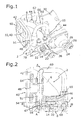
- the pre-cooler shown in the figures has a two-part precooler housing 2, which consists of two housing parts, of which a first housing part is a first flange 4 and a second housing part serves as a flow guide 6.
- the first flange 4 has an exhaust gas inlet 8 which can be attached to an engine block or exhaust manifold.
- This exhaust gas inlet 8 is divided into two parts and leads into a likewise two-part exhaust gas duct 10, whose flow cross-section can be regulated by means of a valve 12.
- the valve 12 consists of a rotary shaft 14, on which two valve bodies 16 are arranged rotationally fixed, wherein each exhaust passage 10 is associated with a valve body 16.
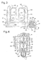
- the bearing of the rotary shaft 14 via a total of three plain bearings 18 which is formed in a bearing bore 20 of the flange 4, as in FIG. 4 can be seen.
- the rotary shaft 14 projects laterally out of the first flange 4 with one end.
- an eccentric 22 is arranged non-rotatably, which is coupled via a lever 24 with a second eccentric 26 which is rotatably mounted on a drive shaft 28 of an electromotive actuator 30, so that a rotational movement of the actuator 30 to the rotary shaft 14 of the valve 12th is transmitted.
- a stop element 32 is formed, against which a first end leg 34 of a return spring 36 is present, which surrounds the rotary shaft 14 and an extension 38 of the first flange 4.
- This return spring 36 is designed as a helical spring, which biases the rotary shaft 14 in the closed position of the two valve bodies 16 in a known manner.
- an opposite spring leg 37 bears against a stop 39 on the flange 4.
- the exhaust passage 10 continues in the flow guide 6 and experiences there a deflection by 90 °, 50 that an exhaust gas outlet 40, which is formed in a second flange 42, is arranged perpendicular to the exhaust gas inlet 8.
- the second flange 42 can be connected with its four in the present embodiment, four divided exhaust outlet 40 to a following, not shown exhaust gas heat exchanger.
- the second flange 42 is integrally formed with the Strömungsleitgephaseuse 6, which is connected via screws 44 which are inserted through through holes 46 of the Strömungsleitgephaseuses 6 and in the first flange 4 formed corresponding through holes 47, with the engine block or the exhaust manifold.
- the flange 4 is simultaneously connected to the Strömungsleitgephaseuse 6 with the interposition of a seal, not shown.
- pre-cooler 2 can take over its cooling function a plurality of interconnected coolant channels are formed in the pre-cooler housing.
- a coolant inlet 48 and a coolant outlet 50 are formed, which extend perpendicular to the second flange 42 and in coolant channels 51, 52 open, each perpendicular to the coolant inlet 48 and coolant outlet 50 and extend to the opposite ends of Flow guide 6 extend so that they surround the exhaust passage 10 on two opposite sides.
- connection channels 54, 56 which extend the coolant channels 51, 52, to two opposite ends of a coolant channel 58 arranged in the first flange 4, which extends parallel to the rotary shaft 14 in the first flange 4 ,
- the opposite ends of the coolant channels 51, 52 are connected to pipes 60, 62, which protrude with the interposition of sealing rings 64 in the coolant channels 51, 52.
- the pipelines 60, 62 extend in a U-shape to the side remote from the second flange 42 of the Strömungsleitgephaseuses 6, where the pipes 60, 62 in turn with the interposition of a seal, not shown in coolant passages 65, 66 projecting from the Strömungsleitgephaseuse 6 in the first flange. 4 extend where they open into opposite ends of a coolant channel 68 extending in the first flange 4 parallel to the rotary shaft 14, however, on the coolant channel 58 opposite side of the rotary shaft 14.
- the coolant channels 58, 68 designed as open holes in the first flange 4, which are closed by plugs 70, 72.
- Coolant flowing in through the coolant inlet 48 is divided in the coolant channel 51, wherein a partial flow flows via the connecting channel 54 to the coolant channel 58 arranged in the first flange 4, while the other partial stream flows via the pipeline 60 and the coolant channel 65 into the coolant channel 58 and to the coolant channel Rotary shaft 14 in the first flange 4 extending coolant channel 68 flows. While the coolant flows from the coolant channel 58 on the opposite side via the connecting channel 56 and the lower part of the coolant channel 52 to the coolant outlet 50, the coolant passes from the coolant channel 68 via the coolant channel 66 and the pipe 62 to the coolant channel 52, from which it flows to the coolant outlet 50 and leaves the pre-cooler housing 2.
- the entire pre-cooler housing 2 is flowed through evenly. Both in the region of the separately formed first flange, at which the heat input is highest, and in the flow guide 6, a high heat dissipation via the coolant can be achieved in this way. As a result, the actuator 30 is protected from overheating. Furthermore, less expensive materials can be used for the housings. This good cooling effect of the pre-cooler while accommodating an exhaust gas recirculation valve or a bypass valve, a subsequent heat exchanger can be built much smaller, since the temperature is dissipated directly at the entrance to a large extent.
- the proposed structure is also suitable for large flow rates, as they occur in particular in commercial vehicles.
- the first flange can be made in one piece with the Strömungsleitgephinuse or another housing part can be used in the region of the second flange.
Landscapes
- Engineering & Computer Science (AREA)
- Chemical & Material Sciences (AREA)
- Combustion & Propulsion (AREA)
- Mechanical Engineering (AREA)
- General Engineering & Computer Science (AREA)
- Exhaust Silencers (AREA)
- Exhaust-Gas Circulating Devices (AREA)
- Details Of Valves (AREA)
Applications Claiming Priority (1)
| Application Number | Priority Date | Filing Date | Title |
|---|---|---|---|
| DE102010014845A DE102010014845A1 (de) | 2010-04-13 | 2010-04-13 | Vorkühler |
Publications (3)
| Publication Number | Publication Date |
|---|---|
| EP2378092A2 EP2378092A2 (de) | 2011-10-19 |
| EP2378092A3 EP2378092A3 (de) | 2011-11-09 |
| EP2378092B1 true EP2378092B1 (de) | 2014-06-18 |
Family
ID=44356261
Family Applications (1)
| Application Number | Title | Priority Date | Filing Date |
|---|---|---|---|
| EP11159341.4A Not-in-force EP2378092B1 (de) | 2010-04-13 | 2011-03-23 | Vorkühler |
Country Status (3)
| Country | Link |
|---|---|
| EP (1) | EP2378092B1 (es) |
| DE (1) | DE102010014845A1 (es) |
| ES (1) | ES2495865T3 (es) |
Families Citing this family (5)
| Publication number | Priority date | Publication date | Assignee | Title |
|---|---|---|---|---|
| DE102010045259A1 (de) | 2010-09-14 | 2012-03-15 | Pierburg Gmbh | Kühlanordnung |
| DE102012103374B4 (de) * | 2012-04-18 | 2015-01-08 | Pierburg Gmbh | Abgasklappenvorrichtung für eine Verbrennungskraftmaschine |
| DE102015006100A1 (de) | 2015-05-09 | 2016-11-10 | Motorenfabrik Hatz Gmbh & Co Kg | Vorrichtung und Verfahren zur Abgasrückführung |
| FR3063306B1 (fr) * | 2017-02-27 | 2019-04-12 | Faurecia Systemes D'echappement | Ensemble avec une vanne a arbre d'entrainement refroidi pour ligne d'echappement |
| WO2020177864A1 (en) * | 2019-03-06 | 2020-09-10 | Mahle International Gmbh | Exhaust gas cooler |
Citations (2)
| Publication number | Priority date | Publication date | Assignee | Title |
|---|---|---|---|---|
| EP1420158A2 (en) * | 2002-11-15 | 2004-05-19 | Denso Corporation | Exhaust gas recirculation device |
| EP1643097A1 (en) * | 2004-09-20 | 2006-04-05 | Mark Iv Systemes Moteurs (Sas) | Multifunctional module, motor vehicle comprising such a module and process for manufacturing such a module |
Family Cites Families (3)
| Publication number | Priority date | Publication date | Assignee | Title |
|---|---|---|---|---|
| DE10321638A1 (de) * | 2002-05-15 | 2004-01-08 | Behr Gmbh & Co. Kg | Schaltbarer Abgaswärmetauscher |
| JP2004169614A (ja) | 2002-11-20 | 2004-06-17 | Denso Corp | 排気ガス再循環制御装置 |
| US8443593B2 (en) * | 2008-12-12 | 2013-05-21 | Westcast Industries, Inc. | Liquid-cooled exhaust valve assembly |
-
2010
- 2010-04-13 DE DE102010014845A patent/DE102010014845A1/de not_active Withdrawn
-
2011
- 2011-03-23 EP EP11159341.4A patent/EP2378092B1/de not_active Not-in-force
- 2011-03-23 ES ES11159341.4T patent/ES2495865T3/es active Active
Patent Citations (2)
| Publication number | Priority date | Publication date | Assignee | Title |
|---|---|---|---|---|
| EP1420158A2 (en) * | 2002-11-15 | 2004-05-19 | Denso Corporation | Exhaust gas recirculation device |
| EP1643097A1 (en) * | 2004-09-20 | 2006-04-05 | Mark Iv Systemes Moteurs (Sas) | Multifunctional module, motor vehicle comprising such a module and process for manufacturing such a module |
Also Published As
| Publication number | Publication date |
|---|---|
| EP2378092A2 (de) | 2011-10-19 |
| EP2378092A3 (de) | 2011-11-09 |
| DE102010014845A1 (de) | 2011-10-13 |
| ES2495865T3 (es) | 2014-09-17 |
Similar Documents
| Publication | Publication Date | Title |
|---|---|---|
| EP2616657B1 (de) | Kühlanordnung | |
| EP2025911B1 (de) | Abgaskühlvorrichtung für eine Verbrennungskraftmaschine | |
| DE102012103374B4 (de) | Abgasklappenvorrichtung für eine Verbrennungskraftmaschine | |
| EP2018472A1 (de) | Ventilanordnung für eine abgasrückführeinrichtung | |
| DE102010014843B4 (de) | Abgaskühlmodul für eine Verbrennungskraftmaschine | |
| EP2378092B1 (de) | Vorkühler | |
| EP2175221A2 (de) | Kühleinrichtung | |
| DE102012104612A1 (de) | Regelventil zum Anbau an einen Verbrennungsmotor | |
| DE102010051032A1 (de) | Integrales Verteilergehäuse zur Kühlmittelführung | |
| EP2753815B1 (de) | Abgaskühler für ein abgasrückführsystem sowie ein abgasrückführsystem mit einem derartigen abgaskühler | |
| DE102011001461B4 (de) | Abgasrückführmodul für eine Verbrennungskraftmaschine | |
| DE10228247A1 (de) | Luftansaugkanalsystem | |
| DE102010006038A1 (de) | Vorrichtung zur Regelung eines Fluidstroms | |
| EP3250801B1 (de) | Befestigungsanordnung zum befestigen eines strömungsgehäuses an einem stellergehäuse | |
| DE102016200371A1 (de) | Abgas-Rückführ-Kühler | |
| DE102016214784A1 (de) | Ventileinrichtung einer Brennkraftmaschine | |
| DE102016211725B4 (de) | Ventilanordnung für AGR-Kühler | |
| EP2378104A1 (de) | Abgaskühlmodul für eine Verbrennungskraftmaschine | |
| DE102019131798B4 (de) | Abgasrückführvorrichtung für eine Verbrennungskraftmaschine | |
| DE112020006468B4 (de) | Abgassystem einer Verbrennungskraftmaschine | |
| DE102013107587A1 (de) | Ventil, insbesondere Abgasweiche für einen Verbrennungsmotor | |
| DE102016214086A1 (de) | Wärmeübertrager | |
| DE102016205752A1 (de) | Abgas-Rückführ-Kühler | |
| DE102012023802B4 (de) | Abgasturbolader mit einer Abgasleitvorrichtung | |
| DE202018006540U1 (de) | Vorrichtung zur Kühlung eines Abgasrückführungs (AGR) -Stroms eines Verbrennungsmotors |
Legal Events
| Date | Code | Title | Description |
|---|---|---|---|
| PUAL | Search report despatched |
Free format text: ORIGINAL CODE: 0009013 |
|
| AK | Designated contracting states |
Kind code of ref document: A2 Designated state(s): AL AT BE BG CH CY CZ DE DK EE ES FI FR GB GR HR HU IE IS IT LI LT LU LV MC MK MT NL NO PL PT RO RS SE SI SK SM TR |
|
| AX | Request for extension of the european patent |
Extension state: BA ME |
|
| AK | Designated contracting states |
Kind code of ref document: A3 Designated state(s): AL AT BE BG CH CY CZ DE DK EE ES FI FR GB GR HR HU IE IS IT LI LT LU LV MC MK MT NL NO PL PT RO RS SE SI SK SM TR |
|
| AX | Request for extension of the european patent |
Extension state: BA ME |
|
| RIC1 | Information provided on ipc code assigned before grant |
Ipc: F01N 3/04 20060101AFI20110930BHEP Ipc: F01N 13/08 20100101ALI20110930BHEP |
|
| PUAI | Public reference made under article 153(3) epc to a published international application that has entered the european phase |
Free format text: ORIGINAL CODE: 0009012 |
|
| 17P | Request for examination filed |
Effective date: 20120504 |
|
| 17Q | First examination report despatched |
Effective date: 20130103 |
|
| GRAP | Despatch of communication of intention to grant a patent |
Free format text: ORIGINAL CODE: EPIDOSNIGR1 |
|
| INTG | Intention to grant announced |
Effective date: 20140307 |
|
| GRAS | Grant fee paid |
Free format text: ORIGINAL CODE: EPIDOSNIGR3 |
|
| GRAA | (expected) grant |
Free format text: ORIGINAL CODE: 0009210 |
|
| AK | Designated contracting states |
Kind code of ref document: B1 Designated state(s): AL AT BE BG CH CY CZ DE DK EE ES FI FR GB GR HR HU IE IS IT LI LT LU LV MC MK MT NL NO PL PT RO RS SE SI SK SM TR |
|
| REG | Reference to a national code |
Ref country code: GB Ref legal event code: FG4D Free format text: NOT ENGLISH |
|
| REG | Reference to a national code |
Ref country code: CH Ref legal event code: EP |
|
| REG | Reference to a national code |
Ref country code: AT Ref legal event code: REF Ref document number: 673488 Country of ref document: AT Kind code of ref document: T Effective date: 20140715 |
|
| REG | Reference to a national code |
Ref country code: IE Ref legal event code: FG4D Free format text: LANGUAGE OF EP DOCUMENT: GERMAN |
|
| REG | Reference to a national code |
Ref country code: DE Ref legal event code: R096 Ref document number: 502011003416 Country of ref document: DE Effective date: 20140814 |
|
| REG | Reference to a national code |
Ref country code: ES Ref legal event code: FG2A Ref document number: 2495865 Country of ref document: ES Kind code of ref document: T3 Effective date: 20140917 |
|
| REG | Reference to a national code |
Ref country code: SE Ref legal event code: TRGR |
|
| REG | Reference to a national code |
Ref country code: NL Ref legal event code: T3 |
|
| PG25 | Lapsed in a contracting state [announced via postgrant information from national office to epo] |
Ref country code: GR Free format text: LAPSE BECAUSE OF FAILURE TO SUBMIT A TRANSLATION OF THE DESCRIPTION OR TO PAY THE FEE WITHIN THE PRESCRIBED TIME-LIMIT Effective date: 20140919 Ref country code: CY Free format text: LAPSE BECAUSE OF FAILURE TO SUBMIT A TRANSLATION OF THE DESCRIPTION OR TO PAY THE FEE WITHIN THE PRESCRIBED TIME-LIMIT Effective date: 20140618 Ref country code: NO Free format text: LAPSE BECAUSE OF FAILURE TO SUBMIT A TRANSLATION OF THE DESCRIPTION OR TO PAY THE FEE WITHIN THE PRESCRIBED TIME-LIMIT Effective date: 20140918 Ref country code: LT Free format text: LAPSE BECAUSE OF FAILURE TO SUBMIT A TRANSLATION OF THE DESCRIPTION OR TO PAY THE FEE WITHIN THE PRESCRIBED TIME-LIMIT Effective date: 20140618 Ref country code: FI Free format text: LAPSE BECAUSE OF FAILURE TO SUBMIT A TRANSLATION OF THE DESCRIPTION OR TO PAY THE FEE WITHIN THE PRESCRIBED TIME-LIMIT Effective date: 20140618 |
|
| REG | Reference to a national code |
Ref country code: LT Ref legal event code: MG4D |
|
| PG25 | Lapsed in a contracting state [announced via postgrant information from national office to epo] |
Ref country code: RS Free format text: LAPSE BECAUSE OF FAILURE TO SUBMIT A TRANSLATION OF THE DESCRIPTION OR TO PAY THE FEE WITHIN THE PRESCRIBED TIME-LIMIT Effective date: 20140618 Ref country code: HR Free format text: LAPSE BECAUSE OF FAILURE TO SUBMIT A TRANSLATION OF THE DESCRIPTION OR TO PAY THE FEE WITHIN THE PRESCRIBED TIME-LIMIT Effective date: 20140618 Ref country code: LV Free format text: LAPSE BECAUSE OF FAILURE TO SUBMIT A TRANSLATION OF THE DESCRIPTION OR TO PAY THE FEE WITHIN THE PRESCRIBED TIME-LIMIT Effective date: 20140618 |
|
| PG25 | Lapsed in a contracting state [announced via postgrant information from national office to epo] |
Ref country code: PT Free format text: LAPSE BECAUSE OF FAILURE TO SUBMIT A TRANSLATION OF THE DESCRIPTION OR TO PAY THE FEE WITHIN THE PRESCRIBED TIME-LIMIT Effective date: 20141020 Ref country code: SK Free format text: LAPSE BECAUSE OF FAILURE TO SUBMIT A TRANSLATION OF THE DESCRIPTION OR TO PAY THE FEE WITHIN THE PRESCRIBED TIME-LIMIT Effective date: 20140618 Ref country code: CZ Free format text: LAPSE BECAUSE OF FAILURE TO SUBMIT A TRANSLATION OF THE DESCRIPTION OR TO PAY THE FEE WITHIN THE PRESCRIBED TIME-LIMIT Effective date: 20140618 Ref country code: EE Free format text: LAPSE BECAUSE OF FAILURE TO SUBMIT A TRANSLATION OF THE DESCRIPTION OR TO PAY THE FEE WITHIN THE PRESCRIBED TIME-LIMIT Effective date: 20140618 Ref country code: RO Free format text: LAPSE BECAUSE OF FAILURE TO SUBMIT A TRANSLATION OF THE DESCRIPTION OR TO PAY THE FEE WITHIN THE PRESCRIBED TIME-LIMIT Effective date: 20140618 |
|
| PG25 | Lapsed in a contracting state [announced via postgrant information from national office to epo] |
Ref country code: PL Free format text: LAPSE BECAUSE OF FAILURE TO SUBMIT A TRANSLATION OF THE DESCRIPTION OR TO PAY THE FEE WITHIN THE PRESCRIBED TIME-LIMIT Effective date: 20140618 Ref country code: IS Free format text: LAPSE BECAUSE OF FAILURE TO SUBMIT A TRANSLATION OF THE DESCRIPTION OR TO PAY THE FEE WITHIN THE PRESCRIBED TIME-LIMIT Effective date: 20141018 |
|
| REG | Reference to a national code |
Ref country code: DE Ref legal event code: R097 Ref document number: 502011003416 Country of ref document: DE |
|
| PLBE | No opposition filed within time limit |
Free format text: ORIGINAL CODE: 0009261 |
|
| STAA | Information on the status of an ep patent application or granted ep patent |
Free format text: STATUS: NO OPPOSITION FILED WITHIN TIME LIMIT |
|
| PG25 | Lapsed in a contracting state [announced via postgrant information from national office to epo] |
Ref country code: DK Free format text: LAPSE BECAUSE OF FAILURE TO SUBMIT A TRANSLATION OF THE DESCRIPTION OR TO PAY THE FEE WITHIN THE PRESCRIBED TIME-LIMIT Effective date: 20140618 Ref country code: IT Free format text: LAPSE BECAUSE OF FAILURE TO SUBMIT A TRANSLATION OF THE DESCRIPTION OR TO PAY THE FEE WITHIN THE PRESCRIBED TIME-LIMIT Effective date: 20140618 |
|
| 26N | No opposition filed |
Effective date: 20150319 |
|
| PG25 | Lapsed in a contracting state [announced via postgrant information from national office to epo] |
Ref country code: SI Free format text: LAPSE BECAUSE OF FAILURE TO SUBMIT A TRANSLATION OF THE DESCRIPTION OR TO PAY THE FEE WITHIN THE PRESCRIBED TIME-LIMIT Effective date: 20140618 |
|
| PG25 | Lapsed in a contracting state [announced via postgrant information from national office to epo] |
Ref country code: MC Free format text: LAPSE BECAUSE OF FAILURE TO SUBMIT A TRANSLATION OF THE DESCRIPTION OR TO PAY THE FEE WITHIN THE PRESCRIBED TIME-LIMIT Effective date: 20140618 Ref country code: LU Free format text: LAPSE BECAUSE OF FAILURE TO SUBMIT A TRANSLATION OF THE DESCRIPTION OR TO PAY THE FEE WITHIN THE PRESCRIBED TIME-LIMIT Effective date: 20150323 |
|
| REG | Reference to a national code |
Ref country code: CH Ref legal event code: PL |
|
| REG | Reference to a national code |
Ref country code: IE Ref legal event code: MM4A |
|
| PG25 | Lapsed in a contracting state [announced via postgrant information from national office to epo] |
Ref country code: LI Free format text: LAPSE BECAUSE OF NON-PAYMENT OF DUE FEES Effective date: 20150331 Ref country code: CH Free format text: LAPSE BECAUSE OF NON-PAYMENT OF DUE FEES Effective date: 20150331 Ref country code: IE Free format text: LAPSE BECAUSE OF NON-PAYMENT OF DUE FEES Effective date: 20150323 |
|
| REG | Reference to a national code |
Ref country code: FR Ref legal event code: PLFP Year of fee payment: 6 |
|
| PGFP | Annual fee paid to national office [announced via postgrant information from national office to epo] |
Ref country code: ES Payment date: 20160322 Year of fee payment: 6 Ref country code: NL Payment date: 20160322 Year of fee payment: 6 |
|
| PGFP | Annual fee paid to national office [announced via postgrant information from national office to epo] |
Ref country code: SE Payment date: 20160322 Year of fee payment: 6 Ref country code: GB Payment date: 20160322 Year of fee payment: 6 Ref country code: FR Payment date: 20160322 Year of fee payment: 6 |
|
| PG25 | Lapsed in a contracting state [announced via postgrant information from national office to epo] |
Ref country code: MT Free format text: LAPSE BECAUSE OF FAILURE TO SUBMIT A TRANSLATION OF THE DESCRIPTION OR TO PAY THE FEE WITHIN THE PRESCRIBED TIME-LIMIT Effective date: 20140618 |
|
| REG | Reference to a national code |
Ref country code: AT Ref legal event code: MM01 Ref document number: 673488 Country of ref document: AT Kind code of ref document: T Effective date: 20160323 |
|
| PG25 | Lapsed in a contracting state [announced via postgrant information from national office to epo] |
Ref country code: BG Free format text: LAPSE BECAUSE OF FAILURE TO SUBMIT A TRANSLATION OF THE DESCRIPTION OR TO PAY THE FEE WITHIN THE PRESCRIBED TIME-LIMIT Effective date: 20140618 Ref country code: HU Free format text: LAPSE BECAUSE OF FAILURE TO SUBMIT A TRANSLATION OF THE DESCRIPTION OR TO PAY THE FEE WITHIN THE PRESCRIBED TIME-LIMIT; INVALID AB INITIO Effective date: 20110323 Ref country code: SM Free format text: LAPSE BECAUSE OF FAILURE TO SUBMIT A TRANSLATION OF THE DESCRIPTION OR TO PAY THE FEE WITHIN THE PRESCRIBED TIME-LIMIT Effective date: 20140618 |
|
| PG25 | Lapsed in a contracting state [announced via postgrant information from national office to epo] |
Ref country code: BE Free format text: LAPSE BECAUSE OF NON-PAYMENT OF DUE FEES Effective date: 20150331 |
|
| PG25 | Lapsed in a contracting state [announced via postgrant information from national office to epo] |
Ref country code: AT Free format text: LAPSE BECAUSE OF NON-PAYMENT OF DUE FEES Effective date: 20160323 Ref country code: TR Free format text: LAPSE BECAUSE OF FAILURE TO SUBMIT A TRANSLATION OF THE DESCRIPTION OR TO PAY THE FEE WITHIN THE PRESCRIBED TIME-LIMIT Effective date: 20140618 |
|
| REG | Reference to a national code |
Ref country code: SE Ref legal event code: EUG |
|
| REG | Reference to a national code |
Ref country code: NL Ref legal event code: MM Effective date: 20170401 |
|
| GBPC | Gb: european patent ceased through non-payment of renewal fee |
Effective date: 20170323 |
|
| PG25 | Lapsed in a contracting state [announced via postgrant information from national office to epo] |
Ref country code: SE Free format text: LAPSE BECAUSE OF NON-PAYMENT OF DUE FEES Effective date: 20170324 |
|
| REG | Reference to a national code |
Ref country code: FR Ref legal event code: ST Effective date: 20171130 |
|
| PG25 | Lapsed in a contracting state [announced via postgrant information from national office to epo] |
Ref country code: FR Free format text: LAPSE BECAUSE OF NON-PAYMENT OF DUE FEES Effective date: 20170331 Ref country code: NL Free format text: LAPSE BECAUSE OF NON-PAYMENT OF DUE FEES Effective date: 20170401 |
|
| PG25 | Lapsed in a contracting state [announced via postgrant information from national office to epo] |
Ref country code: GB Free format text: LAPSE BECAUSE OF NON-PAYMENT OF DUE FEES Effective date: 20170323 |
|
| PG25 | Lapsed in a contracting state [announced via postgrant information from national office to epo] |
Ref country code: MK Free format text: LAPSE BECAUSE OF FAILURE TO SUBMIT A TRANSLATION OF THE DESCRIPTION OR TO PAY THE FEE WITHIN THE PRESCRIBED TIME-LIMIT Effective date: 20140618 |
|
| REG | Reference to a national code |
Ref country code: ES Ref legal event code: FD2A Effective date: 20180705 |
|
| PG25 | Lapsed in a contracting state [announced via postgrant information from national office to epo] |
Ref country code: ES Free format text: LAPSE BECAUSE OF NON-PAYMENT OF DUE FEES Effective date: 20170324 |
|
| PG25 | Lapsed in a contracting state [announced via postgrant information from national office to epo] |
Ref country code: AL Free format text: LAPSE BECAUSE OF FAILURE TO SUBMIT A TRANSLATION OF THE DESCRIPTION OR TO PAY THE FEE WITHIN THE PRESCRIBED TIME-LIMIT Effective date: 20140618 |
|
| REG | Reference to a national code |
Ref country code: DE Ref legal event code: R082 Ref document number: 502011003416 Country of ref document: DE Representative=s name: TERPATENT PARTGMBB, DE Ref country code: DE Ref legal event code: R082 Ref document number: 502011003416 Country of ref document: DE Representative=s name: TERPATENT PATENTANWAELTE TER SMITTEN EBERLEIN-, DE |
|
| PGFP | Annual fee paid to national office [announced via postgrant information from national office to epo] |
Ref country code: DE Payment date: 20240321 Year of fee payment: 14 |
|
| REG | Reference to a national code |
Ref country code: DE Ref legal event code: R119 Ref document number: 502011003416 Country of ref document: DE |
|
| PG25 | Lapsed in a contracting state [announced via postgrant information from national office to epo] |
Ref country code: DE Free format text: LAPSE BECAUSE OF NON-PAYMENT OF DUE FEES Effective date: 20251001 |