EP2378085B1 - Système automatisé et méthode de surveillance de la réponse primaire in fréquence pour un turbogénérateur. - Google Patents
Système automatisé et méthode de surveillance de la réponse primaire in fréquence pour un turbogénérateur. Download PDFInfo
- Publication number
- EP2378085B1 EP2378085B1 EP11162745.1A EP11162745A EP2378085B1 EP 2378085 B1 EP2378085 B1 EP 2378085B1 EP 11162745 A EP11162745 A EP 11162745A EP 2378085 B1 EP2378085 B1 EP 2378085B1
- Authority
- EP
- European Patent Office
- Prior art keywords
- contribution
- feedback
- frequency
- power
- compliance
- Prior art date
- Legal status (The legal status is an assumption and is not a legal conclusion. Google has not performed a legal analysis and makes no representation as to the accuracy of the status listed.)
- Active
Links
- 230000004044 response Effects 0.000 title claims description 73
- 238000000034 method Methods 0.000 title claims description 14
- 238000012544 monitoring process Methods 0.000 title description 21
- 230000033228 biological regulation Effects 0.000 claims description 17
- 230000000977 initiatory effect Effects 0.000 claims description 2
- 239000000446 fuel Substances 0.000 description 40
- 230000008859 change Effects 0.000 description 21
- 230000007423 decrease Effects 0.000 description 17
- 239000007789 gas Substances 0.000 description 15
- 238000002485 combustion reaction Methods 0.000 description 7
- 230000003247 decreasing effect Effects 0.000 description 6
- 238000010586 diagram Methods 0.000 description 5
- IJGRMHOSHXDMSA-UHFFFAOYSA-N Atomic nitrogen Chemical compound N#N IJGRMHOSHXDMSA-UHFFFAOYSA-N 0.000 description 4
- 239000000567 combustion gas Substances 0.000 description 3
- 230000000368 destabilizing effect Effects 0.000 description 3
- 238000004519 manufacturing process Methods 0.000 description 3
- 239000000203 mixture Substances 0.000 description 3
- 230000000737 periodic effect Effects 0.000 description 3
- 241000269400 Sirenidae Species 0.000 description 2
- 230000008901 benefit Effects 0.000 description 2
- 230000005540 biological transmission Effects 0.000 description 2
- 238000013461 design Methods 0.000 description 2
- 238000011161 development Methods 0.000 description 2
- 239000012530 fluid Substances 0.000 description 2
- 238000012886 linear function Methods 0.000 description 2
- 239000007788 liquid Substances 0.000 description 2
- 230000007246 mechanism Effects 0.000 description 2
- 229910052757 nitrogen Inorganic materials 0.000 description 2
- 238000010248 power generation Methods 0.000 description 2
- 230000001052 transient effect Effects 0.000 description 2
- XLYOFNOQVPJJNP-UHFFFAOYSA-N water Substances O XLYOFNOQVPJJNP-UHFFFAOYSA-N 0.000 description 2
- 239000003570 air Substances 0.000 description 1
- 238000013459 approach Methods 0.000 description 1
- 238000003491 array Methods 0.000 description 1
- 230000010405 clearance mechanism Effects 0.000 description 1
- 238000004891 communication Methods 0.000 description 1
- 230000008602 contraction Effects 0.000 description 1
- 239000002826 coolant Substances 0.000 description 1
- 230000001687 destabilization Effects 0.000 description 1
- 230000005611 electricity Effects 0.000 description 1
- 230000007613 environmental effect Effects 0.000 description 1
- 230000006698 induction Effects 0.000 description 1
- 238000002347 injection Methods 0.000 description 1
- 239000007924 injection Substances 0.000 description 1
- 238000007620 mathematical function Methods 0.000 description 1
- 230000008569 process Effects 0.000 description 1
- 230000009467 reduction Effects 0.000 description 1
- 230000000087 stabilizing effect Effects 0.000 description 1
- 238000011144 upstream manufacturing Methods 0.000 description 1
- 238000004804 winding Methods 0.000 description 1
Images


Classifications
-
- F—MECHANICAL ENGINEERING; LIGHTING; HEATING; WEAPONS; BLASTING
- F01—MACHINES OR ENGINES IN GENERAL; ENGINE PLANTS IN GENERAL; STEAM ENGINES
- F01D—NON-POSITIVE DISPLACEMENT MACHINES OR ENGINES, e.g. STEAM TURBINES
- F01D15/00—Adaptations of machines or engines for special use; Combinations of engines with devices driven thereby
- F01D15/10—Adaptations for driving, or combinations with, electric generators
-
- H—ELECTRICITY
- H02—GENERATION; CONVERSION OR DISTRIBUTION OF ELECTRIC POWER
- H02P—CONTROL OR REGULATION OF ELECTRIC MOTORS, ELECTRIC GENERATORS OR DYNAMO-ELECTRIC CONVERTERS; CONTROLLING TRANSFORMERS, REACTORS OR CHOKE COILS
- H02P9/00—Arrangements for controlling electric generators for the purpose of obtaining a desired output
- H02P9/04—Control effected upon non-electric prime mover and dependent upon electric output value of the generator
Definitions
- the subject matter disclosed herein relates to a turbine generator monitoring system.
- a large load change on a utility grid or within an industrial facility can cause rapid destabilization of connected generators, particularly low inertia generators.
- the connected generators Initially, in the first several seconds, the connected generators rapidly change in speed and operating frequency in response to the load change. If the change in frequency passes a threshold known as the dead band frequency (e.g., a minimum frequency change), individual generators may perform a primary frequency response (PFR), increasing or decreasing the amount of power generated by each generator proportionally to the change in frequency.
- PFR primary frequency response
- US 2008/ 047275 A1 discloses a method of operating a gas turbine, wherein the gas turbine engine is coupled to an electrical grid operating at a standardized grid frequency value, and the gas turbine includes a combustor coupled in flow communication with a plurality of independent fuel circuits and a compressor.
- the method includes determining a deviation of a grid frequency from the standardized grid frequency value and adjusting fuel flow from a portion of the plurality of fuel circuits while maintaining a substantially constant air flow from the compressor to facilitate controlling a fuel to compressor discharge pressure ratio such that a combustor state does not lag changes in airflow when the combustor responds to the grid frequency deviation.
- the IEEE paper "Frequency support from doubly fed induction generator wind turbines” discloses a wind turbine DFIG control comprising a frequency droop controller for reducing a generator torque set point to provide high frequency response.
- grid operators may require the electrical generators to comply with certain specifications. For example, such a specification may require that a turbine generator provide half of a PFR output power in 15 seconds and all of the PFR output power in 30 seconds.
- a turbine generator provide half of a PFR output power in 15 seconds and all of the PFR output power in 30 seconds.
- a system includes a gas turbine, an electrical generator coupled to the drive, a controller coupled to the gas turbine, and a compliance monitor.
- the gas turbine generates a torque
- the electrical generator provides power to a power grid based on the torque.
- the controller causes the gas turbine to vary the torque in response to a frequency disturbance occurring on the power grid.
- a method includes initiating a primary frequency response of an electrical generator when a grid frequency disturbance occurs before determining a contribution demand of the electrical generator.
- the contribution demand is determined based at least in part on a droop response of the electrical generator and an amount of the frequency disturbance.
- the output of the electrical generator is measured to determine a contribution feedback, which may be compared to the contribution demand.
- the method further includes determining whether the contribution feedback complies with a specification governing a relationship between the contribution feedback and the contribution demand based at least in part on a table defining percent changes in the contribution feedback relative to the contribution demand over time. When the contribution feedback does not comply with the specification governing the relationship between the contribution feedback and the contribution demand at a predetermined time, an indication of such is provided.
- ContributionDMD BaseMW BaseFREQ ⁇ DeltaFREQ DroopDMD ⁇ ⁇ 1
- BaseMW represents a nominal power output of the system
- BaseFREQ represents a nominal frequency of the system
- DeltaFREQ represents a value of the frequency disturbance
- DroopDMD represents a droop response setpoint.
- Present embodiments relate to monitoring an electrical generator for compliance with a specification (e.g., a local power grid rule or regulation, a manufacturing requirement, etc.) while the electrical generator is performing a primary frequency response (PFR) to a frequency disturbance on a power grid.
- a specification e.g., a local power grid rule or regulation, a manufacturing requirement, etc.
- PFR primary frequency response
- the embodiments disclosed below may involve monitoring for compliance with the specification in real-time (e.g., while the PFR is being carried out).
- These embodiments may apply particularly to monitoring the PFR of low-inertia electrical generators, such as aero-derivative turbine generators, which may be relatively susceptible to frequency disturbances on the power grid, but which also may be capable of responding to such disturbances relatively rapidly.
- a primary frequency response may be initiated by a governor of an electrical generator when a frequency disturbance occurs on the power grid, such as when load on the power grid rapidly increases or decreases on the power grid, causing the frequency of the power grid to vary from a nominal frequency (e.g., typically 50Hz or 60Hz).
- the electrical generator may experience a corresponding change in frequency.
- a governor of the electrical generator may initiate the PFR to attempt to stabilize the power grid by increasing or decreasing the output power of the generator based on a preset formula (referred to herein as "droop response").
- a power grid may require that the PFR be carried out in a specific manner.
- a specification e.g., a rule or regulation
- a monitor may assess whether the electrical generator complies with the specification in real-time (e.g., as the PFR is being carried out). In some embodiments, such real-time monitoring may involve periodically comparing the contribution demand to the contribution feedback. Based on instantaneous values or trends of these values, the monitor may issue an alarm or warning if the electrical generator is not currently in compliance with the specification, or is expected not to comply with the specification.
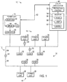
- FIG. 1 is a block diagram of an embodiment of an electrical system 10, which includes a power grid 12 supplied by power units 14 configured to carry out and monitor in real-time a primary frequency response (PFR) in response to frequency-based disturbances of the power grid 12.
- the electrical system 10 includes the power grid 12 coupled to distributed power units 14 and distributed loads 16.
- the distributed power units 14 may include a plurality of power units 20, 22, 24, 26, and 28. Each of these distributed power units 14 is configured to generate power for distribution on the power grid 12.
- the distributed loads 16 may include a plurality of loads 30, 32, 34, 36, and 38. Each of these distributed loads 16 is configured to draw power from the power grid 12 to operate machinery, buildings, and other systems.
- the illustrated electrical system 10 also includes a utility grid system 40 coupled to the power grid 12.
- the utility grid system 40 may provide certain control over the power grid 12 and may detect various grid destabilizing events, such as transient stability upsets, in the power grid 12. These transient stability upsets may correspond to severe changes in frequency or loading on the power grid 12. Additionally, when such events occur, the utility grid system 40 may receive a utility signal 42 from one or more of the power units 14.
- the utility signal 42 may indicate whether the power unit 14 is responding to the disturbance in a manner that complies with a specification associated with the power grid 12 (e.g., a local rule or regulation). In certain embodiments, the utility signal 42 may indicate in real-time whether the response of the power unit 14 complies with the specification.
- the distributed power units 14 may include a variety of power generation systems configured to distribute power onto the power grid 12.
- a distributed power unit 14 may include generators driven by a reciprocating combustion engine, a gas turbine engine, a steam turbine engine, a hydro-turbine, a wind turbine, and so forth.
- the distributed power unit 14 also may include large arrays of solar panels, fuel cells, batteries, or a combination thereof.
- the size of these distributed power units 14 also may vary from one unit to another. For example, one power unit 14 may have a substantially larger inertia than another power unit 14 on the power grid 12.
- the power unit 18 represents a relatively low inertia power unit 14, which includes a drive 44 coupled to a generator 46.
- the power unit 18 also includes a governor 48, which may provide a proportional-acting control of the drive 44.
- the drive 44 is configured to rotate the generator 46 for power generation in response to control by the governor 48 and/or other internal control features.
- the drive 44 may include a low rotating inertia engine, such as a gas turbine engine.
- the drive 44 may include an aero-derivative gas turbine engine, such as an LM1600, LM2500, LM6000, or LMS100 aero-derivative gas turbine engine manufactured by General Electric Company of Schenectady, New York.
- the drive 44 may be any suitable mechanism for rotating the generator 46. As discussed in further detail below, the drive 44 may rapidly change in speed in response to a severe change in load on the power grid 12, thereby causing a rapid change in frequency of power output from the generator 46 onto the power grid 12.
- the distributed loads 16 may include a variety of equipment and facilities on the power grid 12.
- the distributed loads 16 may include residential homes, commercial buildings, industrial facilities, transportation systems, and individual equipment.
- these distributed loads 16 may gradually change electrical demand over each 24 hour period. For example, peak demand may generally occur at midday, while minimum demand may generally occur at midnight. Over the course of the day, the electrical demand by these distributed loads 16 may generally increase in the morning hours, and subsequently decrease in the afternoon hours.
- the distributed power units 14 are generally able to respond to these gradual changes in electrical demand on the power grid 12.
- rapid load swings on the power grid 12 may create a substantial gap between the electrical power supplied by the distributed power unit 16 and the electrical demand by the distributed loads 16.
- a large decrease in load may cause the power units 14 to accelerate, thereby increasing the frequency of the power grid 12.
- a large increase in load may cause the power units to decelerate, thereby decreasing the frequency of the power grid 12.
- the drive 44 may correspondingly increase or decrease in frequency.
- a minimum threshold known as a dead band (e.g., 1mHz, 2mHz, 5mHz, 10mHz, 20mHz, and so forth)
- the governor 48 may initiate a primary frequency response (PFR) intended to assist in stabilizing the power grid 12.
- PFR primary frequency response
- the governor 48 may instruct the drive 44 to add or remove torque to the generator 46 according to a setpoint known as "droop response.” Doing so may add or remove power that, collectively with other distributed power units 14, may return the frequency of the power grid 12 to its nominal frequency.
- a compliance monitor 50 in the power unit 18 is configured to monitor in real-time whether the primary frequency response (PFR) undertaken by the governor 48 complies with a specification.
- the compliance monitor 50 may output, among other things, the utility signal 42 to apprise the utility grid system 40 of whether the power unit 18 is currently in compliance with the specification.
- the utility grid system 40 may be configured to monitor certain system-wide events.
- the utility grid system 40 may include a protection control 52 and a grid monitor 54, which collectively provide rapid event identification and corrective actions based on various grid destabilizing events throughout the power grid 12.
- the grid monitor 54 may include a fault monitor 56, a trip monitor 58, and a swing monitor 60.
- the fault monitor 56 may be configured to rapidly identify a fault, such as a transmission line fault 62, in the power grid 12.
- the fault 62 may represent a discontinuity in first and second portions 64 and 66 of the power grid 12. As a result, the transmission line fault 62 may disconnect loads 36 and 38 and power units 26 and 28 from the first portion 64 of the power grid 12.
- the trip monitor 58 may be configured to identify a trip of one or more of the distributed power units 14, such as a trip 68 of the power unit 22. As a result of the trip 68, the electrical power demand by the distributed loads 16 may suddenly exceed the available power by the distributed power units 14.
- the swing monitor 60 may be configured to identify rapid changes in electrical demand by one or more of the distributed loads 16, such as a swing 70 in the load 32. For example, the swing 70 may represent a sudden increase or decrease in electrical demand in certain equipment, industrial facilities, or the like.
- the compliance monitor 50 may be particularly useful for relatively low-inertia power units 14. Since low-inertia power units 14 may be more susceptible to load changes due to the relatively low inertia of their drives 44, low-inertia power units 14 also may be more likely to operate at lower or higher frequencies when such events occur. Owners or operators of the utility grid system 40 therefore may require such low-inertia power units 14, through a specification (e.g., a local power grid rule or regulation), to respond quickly to ameliorate such frequency changes through a primary frequency response (PFR). For example, the droop response of the governor 48 may be set by an operator of the power unit 18.
- a specification e.g., a local power grid rule or regulation
- the governor 48 may increase or decrease power output by a fractional amount of the total nominal output power of the power unit 18 based on the droop response.
- the owners or operators of the utility grid system 40 may require via a specification that such an increase or decrease in power output must take place within a specified period of time.
- the specification may require that half of such an increase or decrease in power output take place within 15 seconds of a frequency disturbance, and that all of the increase or decrease in power output must take place within 30 seconds.
- Another specification may require that a 100% contribution be provided after a certain amount of time, which must be maintained for another period of time.
- the specification may state that the PFR must be a 100% contribution within 30 seconds, which must be maintained for the following 5 minutes.
- Other specifications may involve meeting or exceeding a minimum function.
- FIG. 12 illustrates a plot 370 that represents such a functional specification.
- An ordinate 372 represents a frequency of the grid 12 and an abscissa 374 represents time.
- a curve 376 represents a functional specification, in which the specification is defined by a particular mathematical function.
- the specification may require that a first initial response (FIR) 378 must take place by a time t1, while a second initial response (SIR) 380 must take place by a time t2.
- FIR first initial response
- SIR second initial response
- the contribution response must meet both the FIR 378 and the SIR 380 to be considered in compliance with the specification.
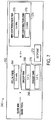
- FIG. 2 is a block diagram of an embodiment of a turbine generator system 100 having a turbine generator controller 102 coupled to a turbine generator 104.
- the turbine generator controller 102 includes a compliance monitor 106, a turbine controller 108, a generator controller 110, and a human machine interface 112.
- the compliance monitor 106 may monitor the primary frequency response (PFR) of the turbine generator 104 for compliance with a specification (e.g., a local power grid rule or regulation). Additionally, the compliance monitor 106 may output a utility signal 114, such as the utility signal 42, to a utility network 116, which may provide the utility signal 114 to the utility grid system 40 as shown in FIG. 1 .
- PFR primary frequency response
- the compliance monitor 106 may output a utility signal 114, such as the utility signal 42, to a utility network 116, which may provide the utility signal 114 to the utility grid system 40 as shown in FIG. 1 .
- the turbine controller 108 may include a variety of monitors and controls, such as a turbine monitor 118, a fuel control 120, a power control 122, and a protection control 124.
- the illustrated generator controller 110 also may include a variety of monitors and controls, such as a generator monitor 126, a voltage control 128, and a protection control 130.
- the monitors and controls of the turbine controller 108 and the generator controller 110 may be configured to monitor and control certain features of the turbine generator 104.
- the turbine generator 104 includes a turbine 140 coupled to a compressor 142 and an electrical generator 144 via one or more shafts 146.
- the illustrated turbine 140 may include one or more turbine stages, and the compressor 142 may include one or more compressor stages.
- the turbine generator 104 also includes one or more combustors 148 and fuel nozzles 150 configured to combust a mixture of fuel 152 and air 154, and deliver hot combustion gases 156 to the turbine 140.
- the compressor 142 is driven by the turbine 140 to compress air 154 at an upstream air intake 158, and then deliver compressed air 160 to the one or more combustors 148 and fuel nozzles 150.
- the fuel nozzles 150 may transmit the compressed air 160 and the fuel 152 into the combustor 148 in a suitable mixture for combustion.
- the mixture of fuel and air then combusts within the combustor 148, thereby producing hot combustion gases 156 flowing into the turbine 140.
- the hot combustion gases 156 drive turbine blades within the turbine 140 to rotate the shaft 146, thereby driving both the compressor 142 and the generator 144.
- the turbine engine may be an aero-derivative gas turbine engine, such as an LM1600, LM2500, LM6000, or LMS100 aero-derivative gas turbine engine manufactured by General Electric Company of Schenectady, New York.
- the turbine generator 104 may be configured to generate up to approximately 14 to 100 MW, 35 to 65 MW, or 40 to 50 MW of electricity.
- the LM2500 engine may be configured to generate up to approximately 18 to 35 MW
- the LM6000 engine may be configured to generate up to approximately 40 to 50 MW
- the LMS100 engine may be configured to generate up to approximately 100 MW.
- the turbine generator controller 102 provides monitoring and control of various features of the turbine generator 104.
- the turbine monitor 118 of the turbine controller 108 may monitor rotational speed, vibration, temperature, pressure, fluid flow, noise, and other parameters of the turbine 140, the compressor 142, the combustor 148, and so forth.
- the fuel control 120 of the turbine controller 108 may be configured to increase or decrease fuel flow to the one or more fuel nozzles 150, thereby changing the combustion dynamics within the combustor 148 and in turn operation of the turbine 140.
- the fuel control 120 may reduce the fuel flow rate to the fuel nozzles 150 to reduce the combustion in the combustor 148, and therefore reduce the speed of the turbine 140.
- the fuel control 120 may increase the fuel flow rate to the fuel nozzles 140 to increase the combustion in the combustor 148, and therefore increase the speed of the turbine 140.
- the fuel control 120 also may vary other characteristics of the fuel injection depending on the number and configuration of fuel nozzles 150.
- the fuel control 120 may adjust multiple independent fuel lines to different fuel nozzles 150 to vary the characteristics of combustion within the combustor 148.
- blocks 152 may correspond to common or independent fuel lines, manifolds, or fuel governors.
- the event responsive control 106 may control various aspects of the fuel control 120.
- the power control 122 of the turbine controller 108 may be configured to increase or decrease power output of the turbine 140.
- the power control 122 may monitor and/or control various operational parameters of the compressor 142, the fuel nozzles 150, the combustor 148, the turbine 140, and external loads (e.g., the generator 144).
- the power control 122 may cooperate with the fuel control 120 to adjust fuel flow, thereby adjusting combustion.
- the power control 122 also may control flow of multiple fuels (e.g., gas and/or liquid fuels), air, water, nitrogen, or various other fluids for various reasons, including performance, emissions, and so forth.
- the power control 122 may selectively enable a gas fuel flow, a liquid fuel flow, or both depending on various conditions and available fuel.
- the power control 122 may selectively enable a low BTU fuel or a high BTU fuel depending on the power requirements. Likewise, the power control 122 may selectively enable water flow, nitrogen flow, or other flows to control emissions.
- the turbine generator controller 102 may control various aspects of the power control 122 to adjust power output during a primary frequency response (PFR), during which time the compliance monitor 106 may assess whether the turbine generator 104 is operating in compliance with a specification (e.g., a power grid rule or regulation).
- PFR primary frequency response
- the protection control 124 of the turbine controller 108 may execute corrective actions in response to events indicative of potential damage, excessive wear, or operational thresholds. For example, if the turbine monitor 118 identifies excessive vibration, noise, or other indicators of potential damage, the protection control 124 may reduce speed or shut down the turbine generator 104 to reduce the possibility of further damage.
- the protection control 124 of the turbine controller 108 may include clearance control, which may provide control of clearance between rotating and stationary components, e.g., in the turbine 140 and/or the compressor 142.
- the clearance control may increase or decrease a coolant flow through the turbine 140 or the compressor 142 to change the thermal expansion or contraction of stationary parts, thereby expanding or contracting the stationary parts (e.g., shroud segments) about the rotating blades.
- the clearance control may increase or decrease the clearance between the rotating blades and the stationary parts in the turbine 140 and the compressor 142.
- the clearance control may control other clearance mechanisms within the turbine 140 or the compressor 142, such as a drive mechanism coupled to the stationary parts disposed about the rotating blades within the turbine 140 or the compressor 142.
- the generator controller 110 also may have a variety of monitor controls to improve performance and reliability of the power output from the turbine generator 104.
- the generator monitor 126 may monitor the various power characteristics of the generator 144, such as voltage, current, and frequency.
- the generator monitor 126 also may monitor various characteristics indicative of wear or damage, such as vibration, noise, or winding faults.
- the voltage control 128 may be configured to process and filter the electrical output from the generator 144, thereby providing the desired electrical output to the power grid.
- the protection control 130 may be configured to take corrective actions in response to feedback from the generator monitor 126, thereby reducing the possibility of damage or excessive damage to the generator 144 or the turbine generator 104 as a whole. For example, the protection control 130 may disconnect the generator 144 from the turbine generator 104, disconnect loads from the generator 144, or shut down the turbine generator 104 in response to excessive vibration or noise identified by the generator monitor 126.
- the generator monitor 126, voltage control 128, and protection control 130 also may provide control scan updates to the compliance compliance monitor 50 indicating, for example, the frequency of the turbine 140 and current power output of the turbine generator 104, from which the compliance monitor 106 may determine compliance with the specification.
- the compliance monitor 106 may include a uniquely programmed computing device, such as a programmed computer system or circuit board, having monitoring instructions that are executable at least when a primary frequency response (PFR) takes place.
- PFR primary frequency response
- the compliance monitor 106 may carry out certain algorithms, such as those discussed below, to ascertain whether the turbine generator 104 complies with, or is likely to comply with, a certain specification.
- FIG. 3 depicts a flowchart 170 of an embodiment of a method for operating the power unit 18 when a frequency-based disturbance occurs on the power grid 12.
- the flowchart 170 may begin as the power unit 18 is generating power at a normal output power level (block 172).
- a normal output power generally may be controlled by an operator of the power unit 18, and may be less than a nominal power output of the power unit 18.
- a frequency-based grid disturbance may occur for a variety of reasons, many of which are discussed above (block 174). For example, if the distributed loads 16 on the power grid 12 rapidly increase or decrease, the frequency of the power grid 12 may correspondingly decrease or increase, and the power unit 18 may respond in kind.
- the frequency of the power grid 12 may drop by a certain percentage.
- the speed of the drive 44 of the power unit 18 also may drop by the same percentage.
- the governor 48 may detect whether the frequency change exceeds a threshold dead band frequency (e.g., 1mHz, 2mHz, 5mHz, 10mHz, 20mHz, or others) (decision block 176). If the frequency change during the grid disturbance does not exceed the dead band, the power unit 18 may continue to generate power at the normal output, generally without regard to the frequency-based grid disturbance (block 172). However, if the frequency change does exceed the dead band, the power unit 18 may begin to carry out a primary frequency response (PFR) to the grid disturbance (block 178). At the same time, the compliance monitor 50 of the power unit 18 may monitor the power unit 18 for compliance with a specification (e.g., power grid rules or regulations) pertaining to the PFR.
- a specification e.g., power grid rules or regulations
- the governor 48 may instruct the drive 44 to increase or decrease the torque to the generator 46, increasing or decreasing the power output of the power unit 18.
- the governor 48 may perform the PFR by increasing the output power (referred to as the "contribution feedback") to match a requested power output (referred to as the "contribution demand") when the frequency disturbance causes a drop in frequency.
- the governor 48 may perform the PFR by decreasing the output power (referred to as the "contribution feedback") to match a requested power output (referred to as the "contribution demand") when the frequency disturbance causes an increase in frequency.
- the contribution demand represents a demanded reduction of power output by the power unit 18.
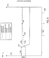
- FIG. 4 is a plot 190 that illustrates a manner in which the power unit 18 may carry out the primary frequency response (PFR) in response to a frequency-based grid disturbance.
- the plot 190 models power output by the power unit 18 (first ordinate 192), and the frequency of the power grid 12 and the power output by the power unit 18 (second ordinate 194), over time (abscissa 196).
- a curve 198 representing the frequency of the power unit 18, begins at a nominal frequency of the power grid 12.
- the frequency of the drive 44 may change rapidly, causing a corresponding change in the frequency of the output power.
- the frequency drops by a certain percentage.
- the additional contribution demand may be calculated according to Equation 1, which may be added to the current contribution demand to obtain a total contribution demand.
- the total contribution demand is represented by a curve 200, which correspondingly increases when the frequency disturbance 204 occurs.
- Another curve 202, representing the contribution feedback illustrates the manner in which the actual power output by the power unit 18 may lag the contribution demand of the curve 202.
- operators or owners of the utility grid system 40 may impose a specification as to how slowly the contribution feedback may meet the contribution demand.
- the specification may require that the contribution feedback exceed half of the additional contribution demand by a first time t1 after a frequency disturbance 200, and that the contribution feedback meet the additional contribution demand by a second time t2 after the frequency disturbance 200.
- These minimum requirements imposed by such a specification are noted at numerals 206 denoting compliance indicators.
- the compliance monitor 50 may undertake a variety of techniques to determine whether the primary frequency response (PFR) complies with the specification. These techniques may involve a variety of potential compliance alarm or warning triggers, as discussed further below.
- the compliance monitor 50 may insure that the power unit 18 remains in compliance with a grid rule or regulation while the power unit 18 responses to a frequency-based grid disturbance.
- FIGS. 5 and 6 describe embodiments of methods for performing such monitoring.
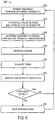
- a flowchart 210 of FIG. 5 describes a manner of periodically ascertaining compliance, beginning when the power unit 18 is carrying out a primary frequency response (PFR) (block 212).
- PFR primary frequency response
- the compliance monitor 50 may perform a scan of the control system on a periodic basis (e.g., every 0.001s, 0.002s, 0.005s, 0.01s, 0.02, 0.05s, 0.1s, 0.2s, 0.5s, 1s, 2s, 5s, or any other suitable period of time) to determine the speed of the generator 46, from which the frequency of the power output by the generator 46 may be determined, and the power output of the generator 46 (block 214).
- the various control and monitoring components of the turbine generator controller 102 may perform such a scan and provide certain relevant information to the compliance monitor 50.
- the compliance monitor 50 may determine contribution demand (block 216) via Equation 1 or 2. The monitor also may determine the contribution feedback by ascertaining the current output power of the power unit 18 (block 218). From these values, the compliance monitor 50 may determine a difference between the contribution demand and the contribution feedback to ascertain an instantaneous feedback error (block 220). Such a feedback error may indicate whether the power unit 18 is performing the primary frequency response (PFR) in compliance with a specification (e.g., a power grid rule or regulation). Thus, based on the instantaneous feedback error, the compliance monitor 50 may consider whether the PFR carried out by the power unit 18 complies with the rule or regulation.
- PFR primary frequency response
- the compliance monitor 50 may compare the contribution feedback and the contribution demand according to a variety of compliance tables or functions. These functions may be, for example, linear, non-linear, or discrete, based on the particular specification, final contribution demand, starting contribution feedback, and time. If the specification discussed above with reference to FIG. 4 is operative, the power unit 18 may not be operating in compliance with the specification when the instantaneous feedback error is less than half the difference between the starting contribution feedback and the final contribution demand.
- the compliance monitor 50 may next consider whether the contribution feedback almost fails to comply with the specification. The monitor may determine whether the feedback error is particularly close to failing to comply based on similar linear, non-linear, or discrete functions or tables. If the monitor determines that the contribution feedback is approaching non-compliance (decision block 224), the compliance monitor 50 may issue a warning (block 226) to alert operators of the power unit 18 or the utility grid system 40 that the power unit 18 could fail to comply with the rule or regulations. Such a warning may be provided via the utility signal 42 or be displayed on the human machine interface 112 of the turbine generator controller 102. In some embodiments, the compliance monitor 50 also may instruct the governor 48 to increase the rate of the primary frequency response (PFR). Regardless of whether the contribution feedback approaches non-compliance (decision block 224), the PFR may continue to take place (block 212).
- PFR primary frequency response
- the compliance monitor 50 may issue an alarm (block 228) that similarly alerts an operator of the power unit 18 or the utility grid system 40 that the power unit 18 is not carrying out the primary frequency response (PFR) in compliance with the specification.
- the alarm may include, among other things, flashing indicator lights, sirens, various voice alerts, or alerts displayed on a display of the human machine interface 112.
- the alarm may also be sent via the utility signal 42 to the utility grid system 40 to indicate the non-compliance of the power unit 18.
- the compliance monitor 50 also may instruct the governor 48 to increase the rate of the PFR. After the compliance monitor 50 issues the alarm, the power unit 18 may continue to perform the PFR (block 212).
- the compliance monitor 50 may also assess whether the power unit 18 complies with a specification (e.g., a power grid rule or regulation) by monitoring trends over time of the contribution feedback and the contribution demand.
- FIG. 6 illustrates a flowchart 240 describing an embodiment of such a method. The flowchart 240 may begin when the power unit 18 is caring out a primary frequency response (PFR) (block 242).
- PFR primary frequency response
- the compliance monitor 50 may perform a scan of the control system on a periodic basis (e.g., every 0.001s, 0.002s, 0.005s, 0.01s, 0.02, 0.05s, 0.1s, 0.2s, 0.5s, 1s, 2s, 5s, or any other suitable period of time) to determine the speed of the generator 46, from which the frequency of the power output by the generator 46 may be determined, and the power output of the generator 46 (block 244).
- the various control and monitoring components of the turbine generator controller 102 may perform such a scan and provide certain relevant information to the compliance monitor 50.
- the monitor may further ascertain the contribution demand by applying Equation 1 or 2 and the contribution feedback by ascertaining the current output power of the power unit 18.
- the contribution feedback and contribution demand may be stored in a database (block 248).
- the compliance monitor 50 may determine historical trends of such values (block 250), which may provide an indication of whether the difference between the contribution demand and the contribution feedback will be likely to comply with the specification (block 252). For example, the contribution feedback over a recent period of time may be increasing at a relatively low rate, making it unlikely that the contribution feedback will rise quickly enough to comply with the specification. If the compliance monitor 50 determines that the trends indicate that compliance is not unlikely (decision block 254), the compliance monitor 50 may not issue any warnings or alarms, and the power unit 18 may continue to perform the primary frequency response (PFR) (block 242).
- PFR primary frequency response
- the compliance monitor 50 may issue certain warnings or alarms (block 256).
- warnings or alarms may include, among other things, flashing indicator lights, sirens, various voice alerts, or alerts displayed on a display of the human machine interface 112.
- the warning or alarm may also be sent via the utility signal 42 to the utility grid system 40 to indicate the non-compliance of the power unit 18.
- the compliance monitor 50 also may instruct the governor 48 to increase the rate of the PFR. After the compliance monitor 50 issues the warning or alarm, the power unit 18 may continue to perform the PFR (block 242).
- the compliance monitor 50 may provide certain information for display on the human machine interface 112.
- One embodiment of such an interface appears as a compliance monitoring screen 260 of FIG. 7 .
- the compliance monitoring screen 260 generally may indicate certain elements of Equations 1 or 2.
- the compliance monitoring screen 260 may indicate certain base values 262, such as the nominal output power and the nominal output frequency of the power unit 18.
- the compliance monitoring screen 260 may depict a current frequency disturbance 264 and certain operator-configurable droop response values 266.
- droop response values for droop feedback 268 and droop demand 270 may be changed by an operator of the power unit 18 by selecting a setpoint button 272.
- Primary frequency response (PFR) values 274, such as the contribution feedback 276 and contribution demand 278, may be displayed on the compliance monitoring screen 260 in real-time, as the PFR takes place.
- PFR Primary frequency response
- FIGS. 8-11 represent embodiments of certain manners in which the compliance monitor 50 may determine whether the power unit 18 is carrying out a primary frequency response (PFR) in compliance with a specification.
- a plot 290 represents one manner in which the power unit 18 may carry out the PFR when the frequency disturbance is so great that the additional contribution demand exceeds the capabilities of the power unit 18.
- the plot 290 models power output by the power unit 18 (first ordinate 292), and the frequency of the power grid 12 and the power output by the power unit 18 (second ordinate 294), over time (abscissa 296).
- a curve 298, representing the frequency of the power unit 18, begins at a nominal frequency of the power grid 12.
- the frequency of the drive 44 may change rapidly, causing a corresponding change in the frequency of the output power.
- the frequency changes dramatically. Indeed, according to Equation 1, if the additional contribution demand was added to the original normal power output, the total contribution demand would exceed the nominal output power of the power unit 18. In such a situation, the governor 48 may lower the total contribution demand, depicted by a curve 300, to a maximum value depending on current environmental conditions rather than an impossible value. Thus, in the illustrated plot 290, the total contribution demand increases to the maximum value when the frequency disturbance 300 occurs.
- the compliance monitor 50 may instead determine compliance based on a contribution demand of the maximum power output, as noted by compliance indicators 306. In certain embodiments, even if compliance does not occur at the compliance indicator 306 at the first time t1, compliance may be deemed to have occurred if the compliance indicator 306 is met at the second time t2.
- FIGS. 9-11 particularly illustrate certain alarm and warning functions that may define when the compliance monitor 50 determines that the power unit 18 is not in compliance with the specification.
- FIGS. 9-11 illustrate the case in which a frequency disturbance causes an output power frequency decrease
- the disclosure associated with FIGS. 9-11 also may be employed for the case in which the frequency disturbance cases an output power frequency increase.
- the frequency disturbance involves an increase that crosses the dead band
- the output from the compliance table may be multiplied by -1, and compliance may thus be monitored in the negative direction.
- a plot 310 represents a linear compliance function, illustrating power (ordinate 312) against time (abscissa 314) and beginning when a frequency disturbance occurs.
- a curve 316 models a contribution demand that results when the governor 48 initiates a primary frequency response (PFR), and a curve 318 models a contribution feedback as the power unit 18 increases its power output to meet the contribution demand.
- Curves 320 and 322 respectively represent triggers for an out of compliance alarm and a compliance warning alarm (e.g., near or approaching non-compliance). That is, if the contribution feedback curve 318 drops below the compliance warning alarm curve 322, the compliance monitor 50 may issue a warning (e.g., near or approaching non-compliance). If the contribution feedback curve 318 drops below the compliance alarm curve 320, the compliance monitor 50 may issue a compliance alarm (e.g., non-compliance).
- the curves 320 and 322 are linear functions that may be represented by a compliance table.
- Table 1 below represents a linear compliance table, from which the curves 320 and 322 may be derived based on the starting contribution feedback and final contribution demand values.
- compliance tables need not end at 30 seconds, nor be tracked in one-second increments.
- a 100-point table could be used, which may be programmed for any suitable time intervals or lengths (e.g., 100 points covering 10 seconds, or 100 points covering 10 minutes). Additionally, responses at times between defined points in compliance tables may be compared against interpolated values during every control scan.
- a plot 330 of FIG. 10 such a function may be discrete values at certain predetermined times.
- the plot 330 represents a discrete compliance function and a linear warning function, illustrating power (ordinate 332) against time (abscissa 334) and beginning when a frequency disturbance occurs.
- a curve 336 models a contribution demand that results when the governor 48 initiates a primary frequency response (PFR), and a curve 338 models a contribution feedback as the power unit 18 increases its power output to meet the contribution demand.
- PFR primary frequency response
- Curves 340 and 342 respectively represent triggers for an out of compliance alarm and a compliance warning alarm (e.g., near or approaching non-compliance). That is, if the contribution feedback curve 338 drops below the compliance warning alarm curve 342, the compliance monitor 50 may issue a warning (e.g., near or approaching non-compliance). If the contribution feedback curve 338 drops below the compliance alarm curve 340, the compliance monitor 50 may issue a compliance alarm (e.g., non-compliance).
- a compliance warning alarm e.g., near or approaching non-compliance
- such compliance functions alternatively may be non-linear functions.
- a plot 350 represents a non-linear compliance function and a parabolic warning function, illustrating power (ordinate 352) against time (abscissa 354) and beginning when a frequency disturbance occurs.
- a curve 356 models a contribution demand that results when the governor 48 initiates a primary frequency response (PFR), and a curve 358 models a contribution feedback as the power unit 18 increases its power output to meet the contribution demand.
- Curves 360 and 362 respectively represent triggers for an out of compliance alarm and a compliance warning alarm (e.g., near or approaching non-compliance).
- the compliance monitor 50 may issue a warning (e.g., near or approaching non-compliance). If the contribution feedback curve 358 drops below the compliance alarm curve 360, the compliance monitor 50 may issue a compliance alarm (e.g., non-compliance).
Landscapes
- Engineering & Computer Science (AREA)
- Mechanical Engineering (AREA)
- General Engineering & Computer Science (AREA)
- Power Engineering (AREA)
- Control Of Eletrric Generators (AREA)
Claims (11)
- Système comprenant :une turbine à gaz (140) configurée pour générer un couple ;un générateur électrique (144) couplé à la turbine à gaz (140), le générateur électrique (144) étant conçu pour fournir de l'énergie à un réseau électrique (12) en fonction du couple ; etun dispositif de commande (102) couplé à la turbine à gaz (140),caractérisé parle fait que le dispositif de commande est conçu pour amener la turbine à gaz (140) à faire varier le couple comme un retour de contribution (202) à une perturbation de fréquence (198 ; 204) survenant sur le réseau électrique (12) ;
etun moniteur de conformité (50) conçu pour déterminer si le retour de contribution à la perturbation de fréquence est conforme à une certaine spécification pour une relation entre le retour de contribution (202) et une demande de contribution requise (200) par indication de la non-conformité du retour de contribution à la spécification en fonction au moins en partie d'une table définissant des pourcentages de variation de du retour de contribution par rapport à la demande de contribution au cours du temps,la demande de contribution (200) étant déterminée selon la relation suivante :
- Système selon la revendication 1, dans lequel le moniteur de conformité (50) est conçu pour émettre un avertissement, une alarme ou une combinaison de ceux-ci, lorsque le retour de contribution à la perturbation de fréquence n'est pas conforme à la spécification.
- Système selon la revendication 1 ou 2, dans lequel le moniteur de conformité (50) est conçu pour prédire si le retour de contribution à la perturbation de fréquence est susceptible de respecter la spécification à l'avenir.
- Système selon la revendication 3, dans lequel le moniteur de conformité (50) est conçu pour émettre un avertissement, une alarme ou une combinaison de ceux-ci lorsque le retour de contribution à la perturbation de fréquence a peu de chances de respecter la spécification.
- Système selon l'une quelconque des revendications précédentes, dans lequel le moniteur de conformité (50) est conçu pour déterminer si le retour de contribution à la perturbation de fréquence est conforme à la spécification lorsque le dispositif de commande (102) effectue le retour de contribution à la perturbation de fréquence.
- Système selon l'une quelconque des revendications précédentes, dans lequel le moniteur de conformité (50) est conçu pour déterminer périodiquement si le retour de contribution à la perturbation de fréquence est conforme à la spécification pendant une certaine durée après la perturbation de fréquence.
- Système selon l'une quelconque des revendications précédentes, dans lequel le moniteur de conformité (50) est conçu pour fournir un signal à un opérateur associé au éseau électrique (12) pour indiquer si le retour de contribution à la perturbation de fréquence est conforme à la spécification.
- Système selon l'une quelconque des revendications précédentes, dans lequel la spécification comprend une règle ou une régulation associée au réseau électrique (12).
- Procédé comprenant :le déclenchement d'une réponse en fréquence primaire d'un générateur électrique lorsd'une perturbation de fréquence du réseau (198 ; 204) ;la détermination d'une demande de contribution (200) du générateur électrique en fonction au moins en partie d'une réponse à la baisse du générateur électrique et d'un degré de la perturbation de fréquence ;la mesure d'une sortie du générateur électrique pour déterminer un retour de contribution (202) ;
etla comparaison du retour de contribution à la demande de contribution ;
etl'indication d'une absence de conformité du retour de contributionà une spécification pour une relation entre le retour de contribution et la demande de contribution à un moment prédéfini par détermination de l'éventuelle conformité du retour de contribution (202) à la spécification au moins en partie sur une table définissant des pourcentages de variation du retour de contribution par rapport à la demande de contribution au cours du temps ;la demande de contribution (200) étant déterminée selon la relation suivante :
- Procédé selon la revendication 9, dans lequel l'indication se produit lorsqu'une différence entre le retour de contribution et la demande de contribution dépasse un certain seuil au moment prédéfini.
- Procédé selon la revendication 9, dans lequel l'indication se produit lorsqu'il est prédit que le retour de contribution a peu de chances de respecter la spécification.
Applications Claiming Priority (1)
| Application Number | Priority Date | Filing Date | Title |
|---|---|---|---|
| US12/763,119 US8463451B2 (en) | 2010-04-19 | 2010-04-19 | Automatic primary frequency response contribution monitoring system and method |
Publications (3)
| Publication Number | Publication Date |
|---|---|
| EP2378085A2 EP2378085A2 (fr) | 2011-10-19 |
| EP2378085A3 EP2378085A3 (fr) | 2018-01-17 |
| EP2378085B1 true EP2378085B1 (fr) | 2021-02-24 |
Family
ID=44070540
Family Applications (1)
| Application Number | Title | Priority Date | Filing Date |
|---|---|---|---|
| EP11162745.1A Active EP2378085B1 (fr) | 2010-04-19 | 2011-04-15 | Système automatisé et méthode de surveillance de la réponse primaire in fréquence pour un turbogénérateur. |
Country Status (2)
| Country | Link |
|---|---|
| US (1) | US8463451B2 (fr) |
| EP (1) | EP2378085B1 (fr) |
Families Citing this family (25)
| Publication number | Priority date | Publication date | Assignee | Title |
|---|---|---|---|---|
| US9690267B2 (en) * | 2011-06-14 | 2017-06-27 | Vestas Wind Systems A/S | Selective droop response control for a wind turbine power plant |
| EP2555141A1 (fr) * | 2011-08-03 | 2013-02-06 | Alcatel Lucent | Procédé, système, serveur, élément de contrôle, programme informatique et produit de programme informatique pour le fonctionnement d'un réseau électrique doté d'éléments de contrôle décentralisés |
| US8907508B2 (en) * | 2011-10-04 | 2014-12-09 | General Electric Company | Load protection system for a turbine |
| WO2013082698A1 (fr) | 2011-12-05 | 2013-06-13 | Hatch Ltd. | Système, procédé et dispositif de commande permettant de gérer et de commander un micro-réseau |
| US9299118B1 (en) * | 2012-04-18 | 2016-03-29 | The Boeing Company | Method and apparatus for inspecting countersinks using composite images from different light sources |
| CN103378601B (zh) * | 2012-04-20 | 2016-03-09 | 华北电力科学研究院有限责任公司 | 一种基于bang-bang控制的一次调频方法及装置 |
| US20130338843A1 (en) * | 2012-06-18 | 2013-12-19 | Reza Iravani | Systems, methods and controllers for control of power distribution devices and systems |
| US9541005B2 (en) * | 2012-09-28 | 2017-01-10 | Pratt & Whitney Canada Corp. | Adaptive fuel manifold filling function for improved engine start |
| US9459671B2 (en) * | 2013-02-25 | 2016-10-04 | General Electric Company | Systems and methods for use in adapting the operation of a gas turbine |
| US9562479B2 (en) | 2013-03-13 | 2017-02-07 | General Electric Company | Systems and methods of droop response control of turbines |
| FR3015672B1 (fr) | 2013-12-23 | 2016-02-05 | Ge Energy Products France Snc | Systeme et procede de test d'une machine tournante |
| US9632011B2 (en) | 2013-12-23 | 2017-04-25 | General Electric Company | System and method for testing a gas turbine |
| US10079564B2 (en) * | 2014-01-27 | 2018-09-18 | General Electric Company | System and method for a stoichiometric exhaust gas recirculation gas turbine system |
| US9819292B2 (en) * | 2014-12-31 | 2017-11-14 | General Electric Company | Systems and methods to respond to grid overfrequency events for a stoichiometric exhaust recirculation gas turbine |
| US9932850B2 (en) * | 2015-02-03 | 2018-04-03 | General Electric Company | Correction system and method for gas turbine proportional droop governor |
| KR101809787B1 (ko) * | 2015-03-10 | 2017-12-15 | 엘에스산전 주식회사 | 배터리 전력 공급 시스템을 포함하는 전력 공급 시스템 |
| CN105019952B (zh) * | 2015-07-01 | 2017-02-01 | 国网天津市电力公司 | 一种提高一次调频负荷响应的控制方法 |
| US10826093B2 (en) | 2016-06-03 | 2020-11-03 | Fuelcell Energy, Inc. | Fuel cell response to electrical grid frequency events |
| FR3060239A1 (fr) * | 2016-12-14 | 2018-06-15 | Ge Energy Products France Snc | Procede de determination d'un profil de reponse en statisme d'une machine electrique reliee a un reseau electrique |
| US10922634B2 (en) * | 2017-05-26 | 2021-02-16 | General Electric Company | Determining compliance of a target asset to at least one defined parameter based on a simulated transient response capability of the target asset and as a function of physical operation data measured during an actual defined event |
| US10442547B2 (en) * | 2017-06-22 | 2019-10-15 | General Electric Company | Engine and electrical machine health monitoring |
| US10613558B2 (en) * | 2017-09-13 | 2020-04-07 | Heatcraft Refrigeration Products Llc | Malfunction lighting |
| JP7110130B2 (ja) | 2018-02-21 | 2022-08-01 | 株式会社東芝 | 発電プラントの蒸気加減弁の制御装置および発電プラントの蒸気加減弁の制御方法 |
| US11063539B2 (en) * | 2019-10-03 | 2021-07-13 | General Electric Company | Methods and systems for rapid load support for grid frequency transient events |
| CN115483691B (zh) * | 2022-11-15 | 2023-02-28 | 华北电力大学 | 储能协调漂浮式风电机组的控制方法及装置 |
Family Cites Families (11)
| Publication number | Priority date | Publication date | Assignee | Title |
|---|---|---|---|---|
| EP0858153B1 (fr) | 1997-02-07 | 2003-04-16 | ALSTOM (Switzerland) Ltd | Procédé de commande d'une centrale électrique |
| AR029828A1 (es) | 2001-07-13 | 2003-07-16 | Petrobras En S A | Metodo para la regulacion primaria de frecuencia en turbinas de vapor de ciclo combinado |
| US7689323B2 (en) * | 2003-05-13 | 2010-03-30 | Siemens Aktiengesellschaft | Automatic generation control of a power distribution system |
| WO2005015366A2 (fr) | 2003-08-08 | 2005-02-17 | Electric Power Group, Llc | Systeme de gestion et de surveillance de resultats en temps reel |
| DK1656722T3 (en) * | 2003-08-15 | 2016-05-23 | Beacon Power Llc | METHODS, SYSTEMS AND APPARATUS FOR REGULATING THE FREQUENCY OF GENERATED POWER USING THE VARIETY WHEEL STORAGE SYSTEMS WITH VARIOUS LOADING AND / OR POWER GENERATION |
| US8019485B2 (en) * | 2004-06-22 | 2011-09-13 | Siemens Energy, Inc. | System and method for controlling the performance of a power generating system |
| US7274111B2 (en) | 2005-12-09 | 2007-09-25 | General Electric Company | Methods and apparatus for electric power grid frequency stabilization |
| US7681401B2 (en) * | 2006-08-24 | 2010-03-23 | General Electric Company | Methods and systems for operating a gas turbine |
| US7608938B2 (en) | 2006-10-12 | 2009-10-27 | General Electric Company | Methods and apparatus for electric power grid frequency stabilization |
| US9020650B2 (en) * | 2007-02-13 | 2015-04-28 | General Electric Company | Utility grid, controller, and method for controlling the power generation in a utility grid |
| DK2235367T3 (en) * | 2007-12-21 | 2016-06-27 | 2-B Energy Holding B V | Wind farm |
-
2010
- 2010-04-19 US US12/763,119 patent/US8463451B2/en active Active
-
2011
- 2011-04-15 EP EP11162745.1A patent/EP2378085B1/fr active Active
Non-Patent Citations (1)
| Title |
|---|
| None * |
Also Published As
| Publication number | Publication date |
|---|---|
| US8463451B2 (en) | 2013-06-11 |
| US20110257801A1 (en) | 2011-10-20 |
| EP2378085A3 (fr) | 2018-01-17 |
| EP2378085A2 (fr) | 2011-10-19 |
Similar Documents
| Publication | Publication Date | Title |
|---|---|---|
| EP2378085B1 (fr) | Système automatisé et méthode de surveillance de la réponse primaire in fréquence pour un turbogénérateur. | |
| EP2557647B1 (fr) | Systèmes et dispositifs pour commander une production d'électricité | |
| US9388753B2 (en) | Generator control having power grid communications | |
| CA2896470C (fr) | Controle de sante de moteur et commande d'attribution de puissance pour un moteur a turbine a l'aide de generateurs electriques | |
| US8498751B2 (en) | Method for early detection and anticipatory control of consumer-end load shedding in an electrical grid, and apparatus for carrying out the method | |
| EP2985845A1 (fr) | Fonctions de protection pour générateurs parallèles | |
| JP5815972B2 (ja) | パワープラント機械の過速度保護システムの試験を行うときを決定する方法 | |
| AU2008274289B2 (en) | Method for the uninterrupted operation of a gas liquefaction system | |
| Meegahapola | Characterisation of gas turbine dynamics during frequency excursions in power networks | |
| EP3396137A1 (fr) | Système de turbine à gaz et son procédé de commande | |
| WO2011023588A2 (fr) | Procédé de commande, dispositif de commande centrale et système pour une éolienne | |
| EP2932093A1 (fr) | Procédé et agencement pour régulation rapide de la puissance | |
| JP2011196380A (ja) | 発電プラントの過速度保護システムを試験する方法及びシステム | |
| EP3800756A1 (fr) | Procédés et systèmes de support de charge rapide pour les événements transitoires à fréquence de réseau | |
| US20160195026A1 (en) | Systems and methods for generating variable ramp rates for turbomachinery | |
| US20220239109A1 (en) | Method for monitoring an electricity supply grid | |
| EP3965250A1 (fr) | Partage de charge avec génération d'énergie interconnectée | |
| US11404879B2 (en) | Systems and methods for improved rate of change of frequency ride-through in electric power systems | |
| DiCampli et al. | Grid stability: Gas turbines for primary reserve | |
| Vlăducă et al. | Automation Control System for Naval Propulsion Retrofitting | |
| Steinkohl et al. | A frequency security analysis of wind integrated power systems with frequency controls | |
| Yang et al. | Automated vibration analysis in loaded condition of hydro turbine generator sets | |
| Agüero et al. | Gas turbine control | |
| Kataoka et al. | Remote monitoring and failure diagnosis for a microturbine cogeneration system | |
| Jayme et al. | CONTROL SYSTEM RETROFIT FOR FIAT TG20 GAS TURBINE POWER UNITS |
Legal Events
| Date | Code | Title | Description |
|---|---|---|---|
| AK | Designated contracting states |
Kind code of ref document: A2 Designated state(s): AL AT BE BG CH CY CZ DE DK EE ES FI FR GB GR HR HU IE IS IT LI LT LU LV MC MK MT NL NO PL PT RO RS SE SI SK SM TR |
|
| AX | Request for extension of the european patent |
Extension state: BA ME |
|
| PUAI | Public reference made under article 153(3) epc to a published international application that has entered the european phase |
Free format text: ORIGINAL CODE: 0009012 |
|
| REG | Reference to a national code |
Ref country code: DE Ref legal event code: R079 Ref document number: 602011070195 Country of ref document: DE Free format text: PREVIOUS MAIN CLASS: F01D0015100000 Ipc: H02P0009040000 |
|
| PUAL | Search report despatched |
Free format text: ORIGINAL CODE: 0009013 |
|
| AK | Designated contracting states |
Kind code of ref document: A3 Designated state(s): AL AT BE BG CH CY CZ DE DK EE ES FI FR GB GR HR HU IE IS IT LI LT LU LV MC MK MT NL NO PL PT RO RS SE SI SK SM TR |
|
| AX | Request for extension of the european patent |
Extension state: BA ME |
|
| RIC1 | Information provided on ipc code assigned before grant |
Ipc: H02H 3/46 20060101ALI20171214BHEP Ipc: H02P 9/04 20060101AFI20171214BHEP Ipc: F01D 15/10 20060101ALI20171214BHEP |
|
| STAA | Information on the status of an ep patent application or granted ep patent |
Free format text: STATUS: REQUEST FOR EXAMINATION WAS MADE |
|
| 17P | Request for examination filed |
Effective date: 20180717 |
|
| RBV | Designated contracting states (corrected) |
Designated state(s): AL AT BE BG CH CY CZ DE DK EE ES FI FR GB GR HR HU IE IS IT LI LT LU LV MC MK MT NL NO PL PT RO RS SE SI SK SM TR |
|
| STAA | Information on the status of an ep patent application or granted ep patent |
Free format text: STATUS: EXAMINATION IS IN PROGRESS |
|
| 17Q | First examination report despatched |
Effective date: 20191001 |
|
| GRAP | Despatch of communication of intention to grant a patent |
Free format text: ORIGINAL CODE: EPIDOSNIGR1 |
|
| STAA | Information on the status of an ep patent application or granted ep patent |
Free format text: STATUS: GRANT OF PATENT IS INTENDED |
|
| INTG | Intention to grant announced |
Effective date: 20200928 |
|
| GRAS | Grant fee paid |
Free format text: ORIGINAL CODE: EPIDOSNIGR3 |
|
| GRAA | (expected) grant |
Free format text: ORIGINAL CODE: 0009210 |
|
| STAA | Information on the status of an ep patent application or granted ep patent |
Free format text: STATUS: THE PATENT HAS BEEN GRANTED |
|
| AK | Designated contracting states |
Kind code of ref document: B1 Designated state(s): AL AT BE BG CH CY CZ DE DK EE ES FI FR GB GR HR HU IE IS IT LI LT LU LV MC MK MT NL NO PL PT RO RS SE SI SK SM TR |
|
| REG | Reference to a national code |
Ref country code: GB Ref legal event code: FG4D |
|
| REG | Reference to a national code |
Ref country code: CH Ref legal event code: EP |
|
| REG | Reference to a national code |
Ref country code: AT Ref legal event code: REF Ref document number: 1365755 Country of ref document: AT Kind code of ref document: T Effective date: 20210315 |
|
| REG | Reference to a national code |
Ref country code: IE Ref legal event code: FG4D |
|
| REG | Reference to a national code |
Ref country code: DE Ref legal event code: R096 Ref document number: 602011070195 Country of ref document: DE |
|
| REG | Reference to a national code |
Ref country code: LT Ref legal event code: MG9D |
|
| REG | Reference to a national code |
Ref country code: NL Ref legal event code: MP Effective date: 20210224 |
|
| PG25 | Lapsed in a contracting state [announced via postgrant information from national office to epo] |
Ref country code: HR Free format text: LAPSE BECAUSE OF FAILURE TO SUBMIT A TRANSLATION OF THE DESCRIPTION OR TO PAY THE FEE WITHIN THE PRESCRIBED TIME-LIMIT Effective date: 20210224 Ref country code: FI Free format text: LAPSE BECAUSE OF FAILURE TO SUBMIT A TRANSLATION OF THE DESCRIPTION OR TO PAY THE FEE WITHIN THE PRESCRIBED TIME-LIMIT Effective date: 20210224 Ref country code: GR Free format text: LAPSE BECAUSE OF FAILURE TO SUBMIT A TRANSLATION OF THE DESCRIPTION OR TO PAY THE FEE WITHIN THE PRESCRIBED TIME-LIMIT Effective date: 20210525 Ref country code: LT Free format text: LAPSE BECAUSE OF FAILURE TO SUBMIT A TRANSLATION OF THE DESCRIPTION OR TO PAY THE FEE WITHIN THE PRESCRIBED TIME-LIMIT Effective date: 20210224 Ref country code: BG Free format text: LAPSE BECAUSE OF FAILURE TO SUBMIT A TRANSLATION OF THE DESCRIPTION OR TO PAY THE FEE WITHIN THE PRESCRIBED TIME-LIMIT Effective date: 20210524 Ref country code: NO Free format text: LAPSE BECAUSE OF FAILURE TO SUBMIT A TRANSLATION OF THE DESCRIPTION OR TO PAY THE FEE WITHIN THE PRESCRIBED TIME-LIMIT Effective date: 20210524 Ref country code: PT Free format text: LAPSE BECAUSE OF FAILURE TO SUBMIT A TRANSLATION OF THE DESCRIPTION OR TO PAY THE FEE WITHIN THE PRESCRIBED TIME-LIMIT Effective date: 20210624 |
|
| REG | Reference to a national code |
Ref country code: AT Ref legal event code: MK05 Ref document number: 1365755 Country of ref document: AT Kind code of ref document: T Effective date: 20210224 |
|
| PG25 | Lapsed in a contracting state [announced via postgrant information from national office to epo] |
Ref country code: SE Free format text: LAPSE BECAUSE OF FAILURE TO SUBMIT A TRANSLATION OF THE DESCRIPTION OR TO PAY THE FEE WITHIN THE PRESCRIBED TIME-LIMIT Effective date: 20210224 Ref country code: NL Free format text: LAPSE BECAUSE OF FAILURE TO SUBMIT A TRANSLATION OF THE DESCRIPTION OR TO PAY THE FEE WITHIN THE PRESCRIBED TIME-LIMIT Effective date: 20210224 Ref country code: RS Free format text: LAPSE BECAUSE OF FAILURE TO SUBMIT A TRANSLATION OF THE DESCRIPTION OR TO PAY THE FEE WITHIN THE PRESCRIBED TIME-LIMIT Effective date: 20210224 Ref country code: LV Free format text: LAPSE BECAUSE OF FAILURE TO SUBMIT A TRANSLATION OF THE DESCRIPTION OR TO PAY THE FEE WITHIN THE PRESCRIBED TIME-LIMIT Effective date: 20210224 Ref country code: PL Free format text: LAPSE BECAUSE OF FAILURE TO SUBMIT A TRANSLATION OF THE DESCRIPTION OR TO PAY THE FEE WITHIN THE PRESCRIBED TIME-LIMIT Effective date: 20210224 |
|
| PG25 | Lapsed in a contracting state [announced via postgrant information from national office to epo] |
Ref country code: IS Free format text: LAPSE BECAUSE OF FAILURE TO SUBMIT A TRANSLATION OF THE DESCRIPTION OR TO PAY THE FEE WITHIN THE PRESCRIBED TIME-LIMIT Effective date: 20210624 |
|
| PG25 | Lapsed in a contracting state [announced via postgrant information from national office to epo] |
Ref country code: CZ Free format text: LAPSE BECAUSE OF FAILURE TO SUBMIT A TRANSLATION OF THE DESCRIPTION OR TO PAY THE FEE WITHIN THE PRESCRIBED TIME-LIMIT Effective date: 20210224 Ref country code: EE Free format text: LAPSE BECAUSE OF FAILURE TO SUBMIT A TRANSLATION OF THE DESCRIPTION OR TO PAY THE FEE WITHIN THE PRESCRIBED TIME-LIMIT Effective date: 20210224 Ref country code: SM Free format text: LAPSE BECAUSE OF FAILURE TO SUBMIT A TRANSLATION OF THE DESCRIPTION OR TO PAY THE FEE WITHIN THE PRESCRIBED TIME-LIMIT Effective date: 20210224 Ref country code: AT Free format text: LAPSE BECAUSE OF FAILURE TO SUBMIT A TRANSLATION OF THE DESCRIPTION OR TO PAY THE FEE WITHIN THE PRESCRIBED TIME-LIMIT Effective date: 20210224 |
|
| REG | Reference to a national code |
Ref country code: DE Ref legal event code: R097 Ref document number: 602011070195 Country of ref document: DE |
|
| PG25 | Lapsed in a contracting state [announced via postgrant information from national office to epo] |
Ref country code: RO Free format text: LAPSE BECAUSE OF FAILURE TO SUBMIT A TRANSLATION OF THE DESCRIPTION OR TO PAY THE FEE WITHIN THE PRESCRIBED TIME-LIMIT Effective date: 20210224 Ref country code: DK Free format text: LAPSE BECAUSE OF FAILURE TO SUBMIT A TRANSLATION OF THE DESCRIPTION OR TO PAY THE FEE WITHIN THE PRESCRIBED TIME-LIMIT Effective date: 20210224 Ref country code: ES Free format text: LAPSE BECAUSE OF FAILURE TO SUBMIT A TRANSLATION OF THE DESCRIPTION OR TO PAY THE FEE WITHIN THE PRESCRIBED TIME-LIMIT Effective date: 20210224 Ref country code: SK Free format text: LAPSE BECAUSE OF FAILURE TO SUBMIT A TRANSLATION OF THE DESCRIPTION OR TO PAY THE FEE WITHIN THE PRESCRIBED TIME-LIMIT Effective date: 20210224 Ref country code: MC Free format text: LAPSE BECAUSE OF FAILURE TO SUBMIT A TRANSLATION OF THE DESCRIPTION OR TO PAY THE FEE WITHIN THE PRESCRIBED TIME-LIMIT Effective date: 20210224 |
|
| PG25 | Lapsed in a contracting state [announced via postgrant information from national office to epo] |
Ref country code: LU Free format text: LAPSE BECAUSE OF NON-PAYMENT OF DUE FEES Effective date: 20210415 |
|
| PLBE | No opposition filed within time limit |
Free format text: ORIGINAL CODE: 0009261 |
|
| STAA | Information on the status of an ep patent application or granted ep patent |
Free format text: STATUS: NO OPPOSITION FILED WITHIN TIME LIMIT |
|
| REG | Reference to a national code |
Ref country code: BE Ref legal event code: MM Effective date: 20210430 |
|
| GBPC | Gb: european patent ceased through non-payment of renewal fee |
Effective date: 20210524 |
|
| PG25 | Lapsed in a contracting state [announced via postgrant information from national office to epo] |
Ref country code: CH Free format text: LAPSE BECAUSE OF NON-PAYMENT OF DUE FEES Effective date: 20210430 Ref country code: AL Free format text: LAPSE BECAUSE OF FAILURE TO SUBMIT A TRANSLATION OF THE DESCRIPTION OR TO PAY THE FEE WITHIN THE PRESCRIBED TIME-LIMIT Effective date: 20210224 Ref country code: LI Free format text: LAPSE BECAUSE OF NON-PAYMENT OF DUE FEES Effective date: 20210430 Ref country code: FR Free format text: LAPSE BECAUSE OF NON-PAYMENT OF DUE FEES Effective date: 20210424 |
|
| 26N | No opposition filed |
Effective date: 20211125 |
|
| PG25 | Lapsed in a contracting state [announced via postgrant information from national office to epo] |
Ref country code: SI Free format text: LAPSE BECAUSE OF FAILURE TO SUBMIT A TRANSLATION OF THE DESCRIPTION OR TO PAY THE FEE WITHIN THE PRESCRIBED TIME-LIMIT Effective date: 20210224 |
|
| PG25 | Lapsed in a contracting state [announced via postgrant information from national office to epo] |
Ref country code: IE Free format text: LAPSE BECAUSE OF NON-PAYMENT OF DUE FEES Effective date: 20210415 Ref country code: GB Free format text: LAPSE BECAUSE OF NON-PAYMENT OF DUE FEES Effective date: 20210524 |
|
| PG25 | Lapsed in a contracting state [announced via postgrant information from national office to epo] |
Ref country code: IS Free format text: LAPSE BECAUSE OF FAILURE TO SUBMIT A TRANSLATION OF THE DESCRIPTION OR TO PAY THE FEE WITHIN THE PRESCRIBED TIME-LIMIT Effective date: 20210624 |
|
| PG25 | Lapsed in a contracting state [announced via postgrant information from national office to epo] |
Ref country code: BE Free format text: LAPSE BECAUSE OF NON-PAYMENT OF DUE FEES Effective date: 20210430 |
|
| PG25 | Lapsed in a contracting state [announced via postgrant information from national office to epo] |
Ref country code: HU Free format text: LAPSE BECAUSE OF FAILURE TO SUBMIT A TRANSLATION OF THE DESCRIPTION OR TO PAY THE FEE WITHIN THE PRESCRIBED TIME-LIMIT; INVALID AB INITIO Effective date: 20110415 Ref country code: CY Free format text: LAPSE BECAUSE OF FAILURE TO SUBMIT A TRANSLATION OF THE DESCRIPTION OR TO PAY THE FEE WITHIN THE PRESCRIBED TIME-LIMIT Effective date: 20210224 |
|
| PGFP | Annual fee paid to national office [announced via postgrant information from national office to epo] |
Ref country code: IT Payment date: 20230322 Year of fee payment: 13 |
|
| P01 | Opt-out of the competence of the unified patent court (upc) registered |
Effective date: 20230522 |
|
| PGFP | Annual fee paid to national office [announced via postgrant information from national office to epo] |
Ref country code: DE Payment date: 20230321 Year of fee payment: 13 |
|
| REG | Reference to a national code |
Ref country code: DE Ref legal event code: R081 Ref document number: 602011070195 Country of ref document: DE Owner name: GENERAL ELECTRIC TECHNOLOGY GMBH, CH Free format text: FORMER OWNER: GENERAL ELECTRIC COMPANY, SCHENECTADY, NY, US |
|
| PG25 | Lapsed in a contracting state [announced via postgrant information from national office to epo] |
Ref country code: MK Free format text: LAPSE BECAUSE OF FAILURE TO SUBMIT A TRANSLATION OF THE DESCRIPTION OR TO PAY THE FEE WITHIN THE PRESCRIBED TIME-LIMIT Effective date: 20210224 |