EP2378046A2 - Device for bulkheading an opening in a room, in particular a door opening (door bulkhead) - Google Patents
Device for bulkheading an opening in a room, in particular a door opening (door bulkhead) Download PDFInfo
- Publication number
- EP2378046A2 EP2378046A2 EP11161674A EP11161674A EP2378046A2 EP 2378046 A2 EP2378046 A2 EP 2378046A2 EP 11161674 A EP11161674 A EP 11161674A EP 11161674 A EP11161674 A EP 11161674A EP 2378046 A2 EP2378046 A2 EP 2378046A2
- Authority
- EP
- European Patent Office
- Prior art keywords
- door
- opening
- air passage
- area
- air
- Prior art date
- Legal status (The legal status is an assumption and is not a legal conclusion. Google has not performed a legal analysis and makes no representation as to the accuracy of the status listed.)
- Granted
Links
- 238000009434 installation Methods 0.000 claims abstract description 9
- 238000000605 extraction Methods 0.000 claims description 12
- 238000007789 sealing Methods 0.000 claims description 9
- 239000000428 dust Substances 0.000 claims description 8
- 239000004033 plastic Substances 0.000 claims description 4
- 238000000638 solvent extraction Methods 0.000 claims description 4
- 230000008859 change Effects 0.000 claims description 2
- 239000002184 metal Substances 0.000 claims description 2
- 229910001220 stainless steel Inorganic materials 0.000 claims description 2
- 239000010935 stainless steel Substances 0.000 claims description 2
- 238000000034 method Methods 0.000 description 6
- 230000008569 process Effects 0.000 description 6
- 238000010276 construction Methods 0.000 description 4
- 238000001914 filtration Methods 0.000 description 3
- 239000002985 plastic film Substances 0.000 description 3
- 238000007639 printing Methods 0.000 description 3
- 238000004140 cleaning Methods 0.000 description 2
- 239000000463 material Substances 0.000 description 2
- 210000002445 nipple Anatomy 0.000 description 2
- 235000003332 Ilex aquifolium Nutrition 0.000 description 1
- 241000209027 Ilex aquifolium Species 0.000 description 1
- 238000005452 bending Methods 0.000 description 1
- 230000015572 biosynthetic process Effects 0.000 description 1
- 239000012141 concentrate Substances 0.000 description 1
- 230000001419 dependent effect Effects 0.000 description 1
- 239000000383 hazardous chemical Substances 0.000 description 1
- 230000036541 health Effects 0.000 description 1
- 238000003780 insertion Methods 0.000 description 1
- 230000037431 insertion Effects 0.000 description 1
- 230000007246 mechanism Effects 0.000 description 1
- 239000007769 metal material Substances 0.000 description 1
- 229920006255 plastic film Polymers 0.000 description 1
- 230000009467 reduction Effects 0.000 description 1
- 238000009418 renovation Methods 0.000 description 1
Images


Classifications
-
- E—FIXED CONSTRUCTIONS
- E06—DOORS, WINDOWS, SHUTTERS, OR ROLLER BLINDS IN GENERAL; LADDERS
- E06B—FIXED OR MOVABLE CLOSURES FOR OPENINGS IN BUILDINGS, VEHICLES, FENCES OR LIKE ENCLOSURES IN GENERAL, e.g. DOORS, WINDOWS, BLINDS, GATES
- E06B5/00—Doors, windows, or like closures for special purposes; Border constructions therefor
- E06B5/10—Doors, windows, or like closures for special purposes; Border constructions therefor for protection against air-raid or other war-like action; for other protective purposes
- E06B5/12—Doors, windows, or like closures for special purposes; Border constructions therefor for protection against air-raid or other war-like action; for other protective purposes against air pressure, explosion, or gas
- E06B5/14—Gasproof doors or similar closures; Adaptation of fixed constructions therefor
-
- E—FIXED CONSTRUCTIONS
- E04—BUILDING
- E04G—SCAFFOLDING; FORMS; SHUTTERING; BUILDING IMPLEMENTS OR AIDS, OR THEIR USE; HANDLING BUILDING MATERIALS ON THE SITE; REPAIRING, BREAKING-UP OR OTHER WORK ON EXISTING BUILDINGS
- E04G21/00—Preparing, conveying, or working-up building materials or building elements in situ; Other devices or measures for constructional work
- E04G21/24—Safety or protective measures preventing damage to building parts or finishing work during construction
- E04G21/241—Safety or protective measures preventing damage to building parts or finishing work during construction for temporarily closing door or window openings
-
- E—FIXED CONSTRUCTIONS
- E04—BUILDING
- E04G—SCAFFOLDING; FORMS; SHUTTERING; BUILDING IMPLEMENTS OR AIDS, OR THEIR USE; HANDLING BUILDING MATERIALS ON THE SITE; REPAIRING, BREAKING-UP OR OTHER WORK ON EXISTING BUILDINGS
- E04G21/00—Preparing, conveying, or working-up building materials or building elements in situ; Other devices or measures for constructional work
- E04G21/24—Safety or protective measures preventing damage to building parts or finishing work during construction
- E04G21/30—Safety or protective measures preventing damage to building parts or finishing work during construction against mechanical damage or dirt, e.g. guard covers of stairs
-
- E—FIXED CONSTRUCTIONS
- E06—DOORS, WINDOWS, SHUTTERS, OR ROLLER BLINDS IN GENERAL; LADDERS
- E06B—FIXED OR MOVABLE CLOSURES FOR OPENINGS IN BUILDINGS, VEHICLES, FENCES OR LIKE ENCLOSURES IN GENERAL, e.g. DOORS, WINDOWS, BLINDS, GATES
- E06B3/00—Window sashes, door leaves, or like elements for closing wall or like openings; Layout of fixed or moving closures, e.g. windows in wall or like openings; Features of rigidly-mounted outer frames relating to the mounting of wing frames
- E06B3/70—Door leaves
- E06B3/80—Door leaves flexible
-
- E—FIXED CONSTRUCTIONS
- E06—DOORS, WINDOWS, SHUTTERS, OR ROLLER BLINDS IN GENERAL; LADDERS
- E06B—FIXED OR MOVABLE CLOSURES FOR OPENINGS IN BUILDINGS, VEHICLES, FENCES OR LIKE ENCLOSURES IN GENERAL, e.g. DOORS, WINDOWS, BLINDS, GATES
- E06B7/00—Special arrangements or measures in connection with doors or windows
- E06B7/02—Special arrangements or measures in connection with doors or windows for providing ventilation, e.g. through double windows; Arrangement of ventilation roses
-
- E—FIXED CONSTRUCTIONS
- E06—DOORS, WINDOWS, SHUTTERS, OR ROLLER BLINDS IN GENERAL; LADDERS
- E06B—FIXED OR MOVABLE CLOSURES FOR OPENINGS IN BUILDINGS, VEHICLES, FENCES OR LIKE ENCLOSURES IN GENERAL, e.g. DOORS, WINDOWS, BLINDS, GATES
- E06B3/00—Window sashes, door leaves, or like elements for closing wall or like openings; Layout of fixed or moving closures, e.g. windows in wall or like openings; Features of rigidly-mounted outer frames relating to the mounting of wing frames
- E06B3/70—Door leaves
- E06B2003/7096—Door leaves with possibilities to alter the extension of the door
-
- E—FIXED CONSTRUCTIONS
- E06—DOORS, WINDOWS, SHUTTERS, OR ROLLER BLINDS IN GENERAL; LADDERS
- E06B—FIXED OR MOVABLE CLOSURES FOR OPENINGS IN BUILDINGS, VEHICLES, FENCES OR LIKE ENCLOSURES IN GENERAL, e.g. DOORS, WINDOWS, BLINDS, GATES
- E06B7/00—Special arrangements or measures in connection with doors or windows
- E06B7/16—Sealing arrangements on wings or parts co-operating with the wings
Definitions
- the invention relates to a device, in particular clamping unit, for partitioning a room opening, in particular a door opening (door bulkhead) for clamping between the side rails of a door frame and the use thereof.
- doors that connect the areas must be temporarily closed so that no contaminated air from the black area can penetrate into the white area. Often it is additionally desired that the door can still be passed by people if necessary. Furthermore, it is often desired for reasons of health and safety to supply this fresh air in the formation of hazardous substances in the black area.
- the term doors is hereinafter used to represent all types of wall openings, it may be any kind of wall opening, such as a door or window cavity, or intended for other use opening, such as a wall opening, which is provided for the insertion of a kitchen hatch , act.
- a device which can be mounted in the region of the upper end of a door opening and carries a curtain made of plastic sheets, which allows a foreclosure of the door opening.
- the device has various disadvantages due to its construction.
- the device is placed with its sealing surfaces from the outside on the wall. In the case of a door frame that protrudes from the wall level, a sufficient seal is problematic.
- any existing door leaf must be dismantled to provide the required contact surface on the wall.
- the device is limited due to their design on doors whose width in a narrow Tolerance range is.
- the device Since the device is secured by means of a telescopic element, which is located spatially in a different plane than the curtain and the cross member carrying the curtain and responsible for the seal, bending moments are also introduced into the device as well as the door carrying the device, which leads to a lead to increased material stress, which is disadvantageous in the case of against mechanical damage sensitive doors, for example in an old building renovation. It is envisaged that the device is clamped with a tensioning device made of two rods with rubber nipples fixed to the end of the rods. On the one hand, the device does not hold properly in the clamped state due to its high weight in the door, since the bearing surface of the rubber nubs for absorbing the forces is much too low.
- the unit has only one air passage opening, so that only one hose can be connected to the unit, with the further disadvantageous consequence that - if the one hose is connected - no further air passage opening is available over which the room fresh air can be supplied ,
- the device can be used only for the negative pressure - and only to a limited extent - in which the intake are occupied directly on the door, with the result that is sucked in the black area directly to the door, again with the result that Under certain circumstances, a short circuit between black and white area forms.
- only an air roller forms directly on the door, with the result that not all the black area can be flushed with a directional air flow necessary for safety at work, again with the result that efficient dust extraction from the black area is not or only very limited is possible.
- the invention has for its object to provide a device for partitioning a room opening, in particular a door opening (door bulkhead), in which the mentioned disadvantages do not occur or to a lesser extent.
- the object is achieved by a device which is clamped between the side rails of a door.
- the device according to the invention is designed so that it is variable in its length in the direction that corresponds in its installation position of the width direction of the door.
- a clamping device is provided which causes this change in length of the device and makes it possible to fix the device between the side rails of a door frame frictionally.
- the device has two air passage openings, which allow for the connection or the passage of air hoses, on the other advantageously be closed by a lid, and further - if an Guteriesöfn Vietnamese is provided with a hose - by leaving open the other air passage opening offers the possibility to supply fresh air to the black area via this.
- receiving elements for adapter pieces are provided on the device, which serve to extend the device in its variable-length direction, so that there is the possibility of making a coarse adjustment of the length of the device to doors of different widths through the adapter pieces.
- Device and adapter pieces are preferably made of a metallic material, which is for example a stainless steel.
- the device and adapter pieces are preferably sheet-like structures made of sheet metal parts.
- the device rests with its edges on the side rails of the door frame, wherein preferably sealing elements are provided at the edges of the device, which provide the seal between the door frame and device.
- the sealing elements may be, for example Plastic lips act, which are preferably made of a soft plastic, such as a rubber material, so that both a sufficient seal as well as a sufficient adhesion of the device with the door frame is made possible, but at the same time a possible damage even a sensitive door frame is avoided.
- Corresponding sealing elements can likewise be provided on the upper edge of the device in the installed position and on the edges of the adapter pieces and / or the edges of the air passage openings.
- variable in length of the device is realized in that the device has two panel-like, slidably interconnected sliding elements.
- the sliding elements are designed such that they overlap and are connected to each other in the overlapping area, for example via guide rails.
- the sliding elements can be moved with the clamping device against each other, whereby the Consunver Surgi the device is effected.
- the tensioning device can advantageously be a lockable toothed wheel which engages in a perforated rail, with the perforated rail and the toothed wheel each being connected to one of the two sliding elements.
- the hole rail may alternatively be designed as a profiling of one of the sliding elements, which allows engagement of the gear.
- the gear is actuated by a pivotable lever which engages with a locking element in the gear.
- the locking element is preferably designed such that it engages only in the movement of the lever in the clamping direction in the gear and so forms a kind of ratchet mechanism for clamping the device, and it is advantageously brought to release the device by another actuator out of engagement with the gear can be.
- the operating element for releasing the tensioning device is attached to the lever for tensioning the tensioning device so that both can be operated with one hand by the same hand.
- the air passage openings are in the region of the ends of the device facing away from one another.
- the sliding elements are contoured on their sides facing each other according to the contours of the air passage openings. This means that the contour is designed so that, for example, in circular air passage openings the mutually facing ends of the sliding elements also have a circular arc-like contour, so that on the one hand a maximum Verschschieb sadness results, on the other hand in the extended state as possible in the region of the upper and lower Edge of the facility at the same time the largest possible overlap area exists.
- a purposeful contouring of the mutually facing ends of the sliding elements does not necessarily simulate the contour of the air passage openings, it is sufficient, for example, to make the contour in the manner of a rectangular recess, so that in the contracted state, the air passage opening of a sliding element at least partially Area of the rectangular recess of the other sliding element is located, while at the same time in the extended state of the sliding element, the non-recessed areas provide an overlap region of both sliding elements for the advantageous guidance of the sliding movement.
- the supplementary usable adapter pieces have at their ends facing each other on a corresponding, for example, semicircular or rectangular account assignment.
- the device For foreclosure of a room, the device is clamped with closed air passage openings at the upper end of a door opening between the side rails of a door.
- plastic louvers or similar suitable elements hereinafter referred to as a curtain, allowed a sufficiently airtight closure of the door.
- a sufficiently airtight closure is to be understood as meaning that the escape of contaminated air from the black area into the white area is prevented to a sufficient extent. Depending on the application, this is already sufficient for a partial closure of the door opening, z. B.
- the curtain may also be designed in a manner passable by persons, for example by overlapping plastic sheets; if a higher degree of sealing is desired with simultaneous passability, for example, the use of airtight zippers is possible.
- a corresponding receptacle for example a Velcro, may be provided in the region of the lower edge of the device for attaching this curtain.
- fan units are considered at this point and hereinafter devices for the promotion of air of any design, which may have in addition to the necessary elements for the promotion function (for example, fans) and facilities for cleaning or filtering the air.
- the term fan units also includes interconnections of air-conveying and air-cleaning / -filtering facilities. If required, larger volumes of air can also be two or more fan units are used, while a corresponding number of openings of the device can be used to pass hoses.
- the device can also be used for maintaining the vacuum of a room, wherein a fan unit installed in the white area or in the black area, preferably in the immediate vicinity of the device, is connected to the other area via a hose guided through the device and thus generates the required negative pressure in the black area.
- the fan unit operates in the suction process, if the fan unit is in the white area, or in the printing process, if the fan unit is in the black area.
- hoses can be raised with a support system in order not to be in the way during the work.
- the system in this construction preferably operates in the printing process by sucking the air through the filters and filtering it through the device out of the black area into the white area.
- the filter fan must be set up directly there. Often, however, it is necessary to perform the dust extraction throughout or a substantial portion of the black area.
- the extraction point for example, by the choice of the installation site of the fan unit, be chosen so that the area dedicated to dust extraction between extraction point and device is located.
- the foreclosure is chosen so that a directed draft, preferably from the device to the extraction point. If the entire space of the black area to be sucked, the extraction point is preferably selected at the location of the room with the greatest distance to the device. In all cases, it is possible and it is achieved that fresh air flows through the open air passage opening of the device.
- the filter fan is set up in the white area, and is connected via the device to the black area via a hose that ends at the workplace or its opening is directly at the workplace.
- the system works in this structure preferably in the suction process.
- a fan unit it is possible, with a fan unit, to convey unencumbered air from a white area through the air passage openings, specifically by means of a hose, into a defined area of the black area.
- the system then operates in the printing process if the filter fan is installed in the white area or in the suction process if the filter valve is installed in the black area.
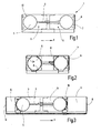
- the device 1 shown by way of example has essentially two panel-like sliding elements 9 which are connected to one another in a displaceable manner and which can be forced apart with the tensioning device 4.
- the air passage openings 5 are located in the region of the ends 10 of the device 1 facing away from one another.
- the mutually facing edges 11 (FIG. Fig. 2 ) of the sliding elements 9 have a contour corresponding to the air passage openings 5.
- the device 1 can be extended by adapters 6, in the example shown (FIG. Fig. 3 ) These can be fixed by bolts 16 which are provided on the sliding elements 9, for example with knurled screws, not shown.
- the sliding elements 9 and the adapter pieces 6 have sealing elements 8 which serve to bear against the inner sides of the side rails 2 of a door 3 ( Fig. 2 ).
- clamping device 4 is realized in the example shown by the engaging in the hole rail 20 gear 18.
- the gear 18 is actuated via the clamping lever 19, which engages with the latching element 21 in the gear 18.
- the actuating element 17 is provided on the clamping lever 19, with which the locking element 21 can be brought out of engagement with the gear 18.
- the gear 18 is then lifted from the hole rail 20, so that the sliding elements 9 of the device 1 are freely strigiebar.
- the device is then fitted in a released state by moving the sliding elements 9 conclusive in the door frame and then firmly clamped by folding down the clamping lever 19 by the gear 18 engages the hole rail 20 and upon realization of the maximum possible clamping the locking element 21 is brought into contact with the gear 18 via the actuating element 17.
- installation position carries the device 1, for example, two-part, on the dividing line and the door frames overlapping curtain 12, which closes the door depending on the application partially or completely, depending on whether a complete foreclosure of the room should be made or if only a reduction of Air passage area that allows a defined afterflow of air into the black area 15, for example, for dust extraction is desired. It is possible to make the curtain 12 so that it is pressed by a negative pressure in the black area 15 to the door frame, resulting in a sealed foreclosure.
- air hoses 22 (FIG. Fig. 7 ) and are passed through the air inlet openings 5 of the device 1 in order to lead air out of the black area 15 into the white area 13 or into the black area 15 from the white area 13.
- sealing elements 8 At the edges 5a of the passage opening 5 sealing elements 8, not shown in the drawing are provided.
Abstract
Description
Die Erfindung betrifft eine Einrichtung, insbesondere Klemmeinheit, zur Abschottung einer Raumöffnung, insbesondere einer Türöffnung (Türschott) zum Einspannen zwischen die Seitenholme eines Türrahmens sowie die Verwendung derselben.The invention relates to a device, in particular clamping unit, for partitioning a room opening, in particular a door opening (door bulkhead) for clamping between the side rails of a door frame and the use thereof.
Häufig ist es notwendig, beispielsweise auf Baustellen, Räume mit belasteter Luft, im Folgenden Schwarzbereiche, von Räumen mit unbelasteter Luft, im Folgenden Weißbereiche, zu trennen. Hierfür müssen Türen, welche die Bereiche verbinden, temporär derart verschlossen werden, dass keine belastete Luft aus dem Schwarzbereich in den Weißbereich dringen kann. Häufig ist es dabei zusätzlich gewünscht, dass die Tür bei Bedarf trotzdem von Personen passiert werden kann. Ferner ist es aus Gründen des Arbeitsschutzes häufig gewünscht, bei Entstehung gefährlicher Stoffe im Schwarzbereich diesem Frischluft zuzuführen. Der Begriff Türen wird im Folgenden stellvertretend für alle Arten von Wanddurchtrittsöffnungen verwendet, dabei kann es sich um jede Art Wanddurchbruch, beispielsweise eine Tür- oder Fensterhöhle, oder eine zur anderweitigen Nutzung vorgesehene Öffnung, beispielsweise eine Wandöffnung, die für das Einsetzen einer Küchendurchreiche vorgesehen ist, handeln.Often it is necessary, for example, on construction sites to separate rooms with contaminated air, hereinafter black areas, from rooms with unencumbered air, hereinafter white areas. For this purpose, doors that connect the areas must be temporarily closed so that no contaminated air from the black area can penetrate into the white area. Often it is additionally desired that the door can still be passed by people if necessary. Furthermore, it is often desired for reasons of health and safety to supply this fresh air in the formation of hazardous substances in the black area. The term doors is hereinafter used to represent all types of wall openings, it may be any kind of wall opening, such as a door or window cavity, or intended for other use opening, such as a wall opening, which is provided for the insertion of a kitchen hatch , act.
Aus der
Der Erfindung liegt die Aufgabe zugrunde, eine Einrichtung zur Abschottung einer Raumöffnung, insbesondere einer Türöffnung (Türschott) zu schaffen, bei der die erwähnten Nachteile nicht oder in vermindertem Maße auftreten.The invention has for its object to provide a device for partitioning a room opening, in particular a door opening (door bulkhead), in which the mentioned disadvantages do not occur or to a lesser extent.
Gelöst wird die Aufgabe durch eine Einrichtung mit den Merkmalen des Anspruchs 1 sowie deren Verwendung gemäß den Ansprüchen 10 bis 12. Die abhängigen Ansprüche betreffen vorteilhafte Ausführungsformen.The object is achieved by a device having the features of
Erfindungsgemäß wird die Aufgabe durch eine Einrichtunggelöst, die zwischen die Seitenholme einer Tür eingespannt wird. Die erfindungsgemäße Einrichtung ist dabei so ausgebildet, dass sie in ihrer Länge in der Richtung, die in ihrer Einbaulage der Breitenrichtung der Tür entspricht, veränderlich ist. Erfindungsgemäß ist dabei eine Spannvorrichtung vorgesehen, die diese Längenänderung der Einrichtung bewirkt und es ermöglicht, die Einrichtung zwischen den Seitenholmen eines Türrahmens kraftschlüssig zu fixieren.According to the invention the object is achieved by a device which is clamped between the side rails of a door. The device according to the invention is designed so that it is variable in its length in the direction that corresponds in its installation position of the width direction of the door. According to the invention a clamping device is provided which causes this change in length of the device and makes it possible to fix the device between the side rails of a door frame frictionally.
Erfindungsgemäß verfügt die Einrichtung dabei über zwei Luftdurchtrittsöffnungen, die zum einen den Anschluss oder die Durchführung von Luftschläuchen ermöglichen, zum anderen vorteilhafterweise durch Deckel verschließbar sind, und ferner - falls eine Luftdurchtrittsöfnnung mit einem Schlauch versehen ist - durch Offenlassen der anderen Luftdurchtrittsöffnung die Möglichkeit bietet, über diese dem Schwarzbereich Frischluft zuzuführen. Vorteilhafterweise sind an der Einrichtung Aufnahmeelemente für Adapterstücke vorgesehen, die dazu dienen, die Einrichtung in ihrer längenveränderlichen Richtung zu verlängern, so dass sich die Möglichkeit ergibt, durch die Adapterstücke eine Grobanpassung der Länge der Einrichtung an Türen unterschiedlicher Breite vorzunehmen. Einrichtung und Adapterstücke sind vorzugsweise aus einem metallischen Werkstoff gefertigt, bei dem es sich beispielsweise um einen nicht rostenden Stahl handelt. Vorzugsweise handelt es sich bei Einrichtung und Adapterstücken um tafelartige Gebilde, die aus Blechteilen gefertigt sind.According to the invention, the device has two air passage openings, which allow for the connection or the passage of air hoses, on the other advantageously be closed by a lid, and further - if an Luftdurchtrittsöfnnung is provided with a hose - by leaving open the other air passage opening offers the possibility to supply fresh air to the black area via this. Advantageously, receiving elements for adapter pieces are provided on the device, which serve to extend the device in its variable-length direction, so that there is the possibility of making a coarse adjustment of the length of the device to doors of different widths through the adapter pieces. Device and adapter pieces are preferably made of a metallic material, which is for example a stainless steel. The device and adapter pieces are preferably sheet-like structures made of sheet metal parts.
Die Einrichtung liegt mit ihren Rändern an den seitlichen Holmen des Türrahmens an, wobei vorzugsweise Dichtelemente an den Rändern der Einrichtung vorgesehen sind, die für die Abdichtung zwischen Türrahmen und Einrichtung sorgen. Bei den Dichtelementen kann es sich beispielsweise um Kunststofflippen handeln, die vorzugsweise aus einem weichen Kunststoff, beispielsweise aus einem Gummimaterial, gefertigt sind, so dass sowohl eine hinreichende Abdichtung wie auch ein ausreichender Kraftschluss der Einrichtung mit dem Türrahmen ermöglicht wird, allerdings gleichzeitig auch eine eventuelle Beschädigung auch eines empfindlichen Türrahmens vermieden wird. Entsprechende Dichtelemente können ebenfalls am in Einbaulage oberen Rand der Einrichtung sowie an den Rändern der Adapterstücke und/oder den Rändern der Luftdurchtrittsöffnungen vorgesehen sein.The device rests with its edges on the side rails of the door frame, wherein preferably sealing elements are provided at the edges of the device, which provide the seal between the door frame and device. The sealing elements may be, for example Plastic lips act, which are preferably made of a soft plastic, such as a rubber material, so that both a sufficient seal as well as a sufficient adhesion of the device with the door frame is made possible, but at the same time a possible damage even a sensitive door frame is avoided. Corresponding sealing elements can likewise be provided on the upper edge of the device in the installed position and on the edges of the adapter pieces and / or the edges of the air passage openings.
Vorteilhafterweise wird die Längenveränderlichkeit der Einrichtung dadurch realisiert, dass die Einrichtung zwei tafelartige, verschieblich miteinander verbundene Schiebeelemente aufweist. Die Schiebeelemente sind dabei derart gestaltet, dass sie sich überlappen und im Überlappungsbereich beispielsweise über Führungsschienen miteinander verbunden sind. Die Schiebeelemente können mit der Spannvorrichtung gegeneinander bewegt werden, wodurch die Längenveränderlichkeit der Einrichtungbewirkt wird.Advantageously, the variable in length of the device is realized in that the device has two panel-like, slidably interconnected sliding elements. The sliding elements are designed such that they overlap and are connected to each other in the overlapping area, for example via guide rails. The sliding elements can be moved with the clamping device against each other, whereby the Längenveränderlichkeit the device is effected.
Bei der Spannvorrichtung kann es sich vorteilhafterweise um ein arretierbares Zahnrad handeln, das in eine Lochschiene eingreift, wobei Lochschiene und Zahnrad jeweils mit einem der beiden Schiebeelemente verbunden sind. Dabei kann die Lochschiene alternativ als Profilierung eines der Schiebeelemente ausgeführt sein, die einen Eingriff des Zahnrads ermöglicht. Vorteilhafterweise wird das Zahnrad durch einen schwenkbaren Hebel betätigt, der mit einem Rastelement in das Zahnrad eingreift. Das Rastelement ist dabei bevorzugt derart ausgebildet, dass es lediglich bei der Bewegung des Hebels in Spannrichtung in das Zahnrad eingreift und so eine Art Ratschenmechanismus zum Einspannen der Einrichtung bildet, wobei es vorteilhafterweise zum Lösen der Einrichtung durch ein weiteres Betätigungselement außer Eingriff mit dem Zahnrad gebracht werden kann. Im Hinblick auf eine ergonomische Bedienung ist das Betätigungselement zum Lösen der Spannvorrichtung derart an dem Hebel zum Spannen der Spannvorrichtung angebracht, dass beide mit der gleichen Hand einhändig bedient werden können.The tensioning device can advantageously be a lockable toothed wheel which engages in a perforated rail, with the perforated rail and the toothed wheel each being connected to one of the two sliding elements. In this case, the hole rail may alternatively be designed as a profiling of one of the sliding elements, which allows engagement of the gear. Advantageously, the gear is actuated by a pivotable lever which engages with a locking element in the gear. The locking element is preferably designed such that it engages only in the movement of the lever in the clamping direction in the gear and so forms a kind of ratchet mechanism for clamping the device, and it is advantageously brought to release the device by another actuator out of engagement with the gear can be. In view of ergonomic operation, the operating element for releasing the tensioning device is attached to the lever for tensioning the tensioning device so that both can be operated with one hand by the same hand.
Im Hinblick auf einen im Vergleich zur Gesamtlänge der Einrichtung möglichst großen Verstellbereich der Länge der Einrichtung ist es vorteilhaft, die Luftdurchtrittsöffnungen im Bereich der voneinander weg weisenden Enden der Schiebeelemente vorzusehen. Vorteilhafterweise sind die Schiebeelemente dabei an ihren aufeinander zu weisenden Seiten entsprechend den Umrissen der Luftdurchtrittsöffnungen konturiert. Dies bedeutet, dass die Kontur so gestaltet ist, dass beispielsweise bei kreisrunden Luftdurchtrittsöffnungen die aufeinander zu weisenden Enden der Schiebeelemente ebenfalls eine kreisbogenartige Kontur aufweisen, so dass sich zum Einen eine größtmögliche Zusammenschiebbarkeit ergibt, zum Anderen im weitestmöglich ausgezogenen Zustand im Bereich des oberen und unteren Randes der Einrichtung gleichzeitig ein größtmöglicher Überlappungsbereich besteht. Dies ist vorteilhaft, da in diesem Überlappungsbereich die Führung der Schiebeelemente ineinander realisiert werden kann. Eine hierfür zweckdienliche Konturierung der aufeinander zu weisenden Enden der Schiebeelemente muss nicht zwangsläufig die Kontur der Luftdurchtrittsöffnungen nachbilden, es genügt beispielweise auch, die Kontur in der Art einer rechteckigen Ausnehmung zu gestalten, so dass sich im zusammengezogenen Zustand die Luftdurchtrittsöffnung des einen Schiebeelementes zumindest teilweise im Bereich der rechteckigen Ausnehmung des anderen Schiebeelementes befindet, während gleichzeitig im ausgezogenen Zustand des Schiebeelementes die nicht ausgenommenen Bereiche einen Überlappungsbereich beider Schiebeelemente für die vorteilhafte Führung der Verschiebebewegung bereitstellen. Die ergänzend verwendbaren Adapterstücke weisen an ihren einander zugewandten Enden eine entsprechende, beispielsweise halbkreisförmige oder rechteckige Kontierung auf.With regard to an adjustment range of the length of the device that is as large as possible compared with the overall length of the device, it is advantageous for the air passage openings to be in the region of the ends of the device facing away from one another Provide sliding elements. Advantageously, the sliding elements are contoured on their sides facing each other according to the contours of the air passage openings. This means that the contour is designed so that, for example, in circular air passage openings the mutually facing ends of the sliding elements also have a circular arc-like contour, so that on the one hand a maximum Verschschiebbarkeit results, on the other hand in the extended state as possible in the region of the upper and lower Edge of the facility at the same time the largest possible overlap area exists. This is advantageous because in this overlapping region, the guidance of the sliding elements can be realized in each other. A purposeful contouring of the mutually facing ends of the sliding elements does not necessarily simulate the contour of the air passage openings, it is sufficient, for example, to make the contour in the manner of a rectangular recess, so that in the contracted state, the air passage opening of a sliding element at least partially Area of the rectangular recess of the other sliding element is located, while at the same time in the extended state of the sliding element, the non-recessed areas provide an overlap region of both sliding elements for the advantageous guidance of the sliding movement. The supplementary usable adapter pieces have at their ends facing each other on a corresponding, for example, semicircular or rectangular account assignment.
Zur Abschottung eines Raumes wird die Einrichtung mit verschlossenen Luftdurchtrittsöffnungen am oberen Ende einer Türöffnung zwischen die Seitenholme einer Tür geklemmt. An der Einrichtung werden vorzugsweise an ihrem unteren Rand Kunststofffolien, Kunststofflamellen oder ähnliche geeignete Elemente vorgesehen, die im Folgenden als Vorhang bezeichnet, einen hinreichend luftdichten Abschluss der Tür ermöglichten. Unter einem hinreichend luftdichten Abschluss ist dabei zu verstehen, dass das Austreten belasteter Luft aus dem Schwarzbereich in den Weißbereich in ausreichendem Maße verhindert wird. Je nach Anwendungsfall reicht hierfür bereits ein teilweiser Verschluss der Türöffnung aus, z. B. wenn ein Luftdurchtritt von dem Schwarzbereich in den Weißbereich durch eine Druckdifferenz zwischen den beiden Bereichen (z.B. Unterdruckhaltung, s.u.) und eine daraus resultierende erzwungene Luftströmung vom Schwarzbereich in den Weißbereich verhindert wird. Je nach dem Überlappungsgrad des Vorhangs mit der Wand und/oder dem Türrahmen ist es dabei möglich, dass der Vorhang an Wand und/oder Türrahmen angepresst wird, was zu einer besseren Abdichtung führt. In diesen Fällen kann der Vorhang auch in einer von Personen passierbaren Weise, beispielsweise durch sich überlappende Kunststoffbahnen, gestaltet sein; wird ein höherer Grad der Abdichtung bei gleichzeitiger Passierbarkeit gewünscht, ist beispielsweise die Verwendung luftdichter Reißverschlüsse möglich. Vorteilhafterweise kann zur Anbringung dieses Vorhangs eine entsprechende Aufnahme, beispielsweise ein Klettband, im Bereich des unteren Randes der Einrichtung vorgesehen sein.For foreclosure of a room, the device is clamped with closed air passage openings at the upper end of a door opening between the side rails of a door. On the device are preferably provided at its lower edge plastic films, plastic louvers or similar suitable elements, hereinafter referred to as a curtain, allowed a sufficiently airtight closure of the door. A sufficiently airtight closure is to be understood as meaning that the escape of contaminated air from the black area into the white area is prevented to a sufficient extent. Depending on the application, this is already sufficient for a partial closure of the door opening, z. B. if a Air passage from the black area in the white area by a pressure difference between the two areas (eg vacuum position, see below) and a resulting forced air flow from the black area is prevented in the white area. Depending on the degree of overlap of the curtain with the wall and / or the door frame, it is possible that the curtain is pressed against the wall and / or door frame, resulting in a better seal. In these cases, the curtain may also be designed in a manner passable by persons, for example by overlapping plastic sheets; if a higher degree of sealing is desired with simultaneous passability, for example, the use of airtight zippers is possible. Advantageously, a corresponding receptacle, for example a Velcro, may be provided in the region of the lower edge of the device for attaching this curtain.
Als Lüftereinheiten werden an dieser Stelle und im Folgenden Geräte zur Förderung von Luft jeglicher Bauweise betrachtet, die neben den für die Förderfunktion nötigen Elementen (zum Beispiel Ventilatoren) auch Einrichtungen zur Reinigung oder Filterung der Luft aufweisen können. Der Begriff Lüftereinheiten umfasst dabei auch Zusammenschaltungen luftfördernder und luftreinigender/-filternder Einrichtungen. Bei Bedarf größeren Luftvolumens können auch zwei oder mehr Lüftereinheiten verwendet werden, dabei kann eine entsprechende Anzahl Öffnungen der Einrichtung zur Durchführung von Schläuchen genutzt werden.As fan units are considered at this point and hereinafter devices for the promotion of air of any design, which may have in addition to the necessary elements for the promotion function (for example, fans) and facilities for cleaning or filtering the air. The term fan units also includes interconnections of air-conveying and air-cleaning / -filtering facilities. If required, larger volumes of air can also be two or more fan units are used, while a corresponding number of openings of the device can be used to pass hoses.
Die Einrichtung kann auch zur Unterdruckhaltung eines Raumes verwendet werden, wobei eine im Weißbereich oder im Schwarzbereich, vorzugsweise in ummittelbarer Nähe der Einrichtungaufgestellte Lüftereinheit über einen durch die Einrichtung geführten Schlauch mit dem anderen Bereich verbunden wird und so im Schwarzbereich den erforderlichen Unterdruck erzeugt. Dabei arbeitet die Lüftereinheit im Saugverfahren, falls die Lüftereinheit im Weißbereich steht, oder im Druckverfahren, falls die Lüftereinheit im Schwarzbereich steht.The device can also be used for maintaining the vacuum of a room, wherein a fan unit installed in the white area or in the black area, preferably in the immediate vicinity of the device, is connected to the other area via a hose guided through the device and thus generates the required negative pressure in the black area. The fan unit operates in the suction process, if the fan unit is in the white area, or in the printing process, if the fan unit is in the black area.
Ferner ist es möglich, zur Staubabsaugung ein oder zwei Lüftereinheiten im Schwarzbereich zu installieren und über Schläuche durch die Einrichtung hindurch mit dem Weißbereich zu verbinden. Die Schläuche können mit einem Stützensystem aufgeständert werden, um bei den Arbeiten nicht im Weg zu sein. Das System arbeitet in diesem Aufbau vorzugsweise im Druckverfahren, indem die Luft über die Filter gesaugt und durch die Einrichtung hindurch aus dem Schwarzbereich gefiltert in den Weißbereich gedrückt wird.Furthermore, it is possible to install one or two fan units in the black area for dust extraction and to connect them via hoses through the device to the white area. The hoses can be raised with a support system in order not to be in the way during the work. The system in this construction preferably operates in the printing process by sucking the air through the filters and filtering it through the device out of the black area into the white area.
Soll der Staub gezielt am Arbeitsplatz abgesaugt werden, so ist der Filterventilator direkt dort aufzustellen. Oft ist es jedoch nötig, die Staubabsaugung im gesamten oder einem wesentlichen Teil des Schwarzbereichs vorzunehmen. Hierfür kann die Absaugstelle, beispielsweise durch die Wahl des Aufstellungsortes der Lüftereinheit, so gewählt werden, dass sich der zur Staubabsaugung bestimmte Bereich zwischen Absaugstelle und Einrichtung befindet. Die Abschottung wird dabei so gewählt, dass ein gerichteter Luftzug, vorzugsweise von der Einrichtung bis zur Absaugstelle entsteht. Soll der ganze Raum des Schwarzbereichs abgesaugt werden, so wird die Absaugstelle vorzugsweise an der Stelle des Raumes mit dem größten Abstand zur Einrichtung gewählt. In allen Fällen ist es möglich und wird es erreicht, dass Frischluft durch die geöffnete Luftdurchtrittsöffnung der Einrichtung nachströmt.If the dust is to be specifically extracted at the workplace, the filter fan must be set up directly there. Often, however, it is necessary to perform the dust extraction throughout or a substantial portion of the black area. For this purpose, the extraction point, for example, by the choice of the installation site of the fan unit, be chosen so that the area dedicated to dust extraction between extraction point and device is located. The foreclosure is chosen so that a directed draft, preferably from the device to the extraction point. If the entire space of the black area to be sucked, the extraction point is preferably selected at the location of the room with the greatest distance to the device. In all cases, it is possible and it is achieved that fresh air flows through the open air passage opening of the device.
Ferner ist es möglich, die beschriebene Absaugung am Arbeitsplatz zu erreichen, indem der Filterventilator im Weissbereich aufgestellt wird, und über die Einrichtung mit dem Schwarzbereich über einen Schlauch verbunden ist, der am Arbeitsplatz endet bzw. dessen Öffnung direkt am Arbeitsplatz liegt. Das System arbeitet in diesem Aufbau vorzugsweise im Saugverfahren.Furthermore, it is possible to achieve the described extraction in the workplace by the filter fan is set up in the white area, and is connected via the device to the black area via a hose that ends at the workplace or its opening is directly at the workplace. The system works in this structure preferably in the suction process.
Ebenso ist es möglich, mit einer Lüftereinheit unbelastete Luft aus einem Weißbereich durch die Luftdurchtrittsöffnungen gezielt mittels Schlauch in einen definierten Bereich des Schwarzbereiches zu fördern. Das System arbeitet dann im Druckverfahren, falls der Filterventilator im Weissbereich aufgestellt ist, bzw. im Saugverfahren, falls der Filterventiltor im Schwarzbereich aufgestellt ist.Likewise, it is possible, with a fan unit, to convey unencumbered air from a white area through the air passage openings, specifically by means of a hose, into a defined area of the black area. The system then operates in the printing process if the filter fan is installed in the white area or in the suction process if the filter valve is installed in the black area.
Die Erfindung wird im Folgenden anhand von Ausführungsbeispielen erläutert, die in den
-
Fig. 1 eine beispielhafte erfindungsgemäße Einrichtung im ausgezogenen Zustand in einer Ansicht in Einbaulage. -
Fig. 2 eine Einrichtung gemäßFig. 1 im zusammengeschobenen Zustand. -
Fig. 3 eine weitere Ausführungsform einer Einrichtung mit angesetzten Adapterstücken in Einbaulage. -
Fig. 4 eine weitere Ausführungsform einer Einrichtung in Einbaulage einer Ansicht von oben (Teildarstellung). -
Fig. 5 die Einrichtung gemäßFig. 4 mit der gelöster Stellung des Spannhebels und damit in diesem Zustand frei auseinanderziehbaren oder zusammenschiebbaren Einrichtung. -
Fig. 6 die Anwendung einer erfindungsgemäßen Einrichtung zur Abschottung eines Raumes. -
Fig. 7 das allgemeine Funktionsprinzip der Klemmeinheit. -
Fig. 8 die Anwendung einer erfindungsgemäßen Einrichtung zur Unterdruckhaltung eines Raumes. -
Fig. 9 die Anwendung einer erfindungsgemäßen Einrichtung zur Staubabsaugung.
-
Fig. 1 an exemplary device according to the invention in the extended state in a view in installation position. -
Fig. 2 a device according toFig. 1 in the collapsed state. -
Fig. 3 a further embodiment of a device with attached adapter pieces in the installed position. -
Fig. 4 a further embodiment of a device in installation position of a view from above (partial view). -
Fig. 5 the device according toFig. 4 with the released position of the clamping lever and thus freely expandable or collapsible device in this state. -
Fig. 6 the application of a device according to the invention for foreclosing a room. -
Fig. 7 the general operating principle of the clamping unit. -
Fig. 8 the application of a device according to the invention for keeping the negative pressure of a room. -
Fig. 9 the application of a device according to the invention for dust extraction.
In den Figuren sind gleiche Teile mit den gleichen Bezugszeichen versehen. Die in
Die in den
In der in
An die Lüftereinheiten 14 können Luftschläuche 22 (
- 11
- Klemmeinheitterminal unit
- 22
- HolmHolm
- 33
- Türdoor
- 44
- Spannvorrichtungjig
- 55
- LuftdurchtrittsöffnungenAir passage openings
- 5a5a
- Rändermargins
- 66
- Adapterstückadapter piece
- 77
- Rändermargins
- 88th
- Dichtelementsealing element
- 99
- Schiebeelementesliding elements
- 1010
- EndeThe End
- 1111
- Rändermargins
- 1212
- Vorhangcurtain
- 1313
- WeißbereichWhite area
- 1414
- Lüftereinheitfan unit
- 1515
- SchwarzbereichBlack area
- 1616
- Bolzenbolt
- 1717
- Betätigungselementactuator
- 1818
- Zahnradgear
- 1919
- Spannhebelclamping lever
- 2020
- Lochschieneperforated rail
- 2121
- Rastelementlocking element
- 2222
- Luftschläucheair hoses
Claims (14)
dadurch gekennzeichnet,
dass die Spannvorrichtung (4) durch ein Betätigungselement (17) entsperrbar ist, vorzugsweise indem ein Rastelement (21) außer Zugriff mit dem Zahnrad (18) gebracht werden kannDevice according to claim 8,
characterized,
in that the tensioning device (4) can be unlocked by an actuating element (17), preferably in that a latching element (21) can be brought out of access with the gearwheel (18)
Applications Claiming Priority (2)
| Application Number | Priority Date | Filing Date | Title |
|---|---|---|---|
| DE201010015005 DE102010015005A1 (en) | 2010-04-14 | 2010-04-14 | Clamping unit for a door bulkhead |
| DE202010014966U DE202010014966U1 (en) | 2010-04-14 | 2010-10-30 | Device for partitioning off a room opening, in particular a door opening (door bulkhead) |
Publications (3)
| Publication Number | Publication Date |
|---|---|
| EP2378046A2 true EP2378046A2 (en) | 2011-10-19 |
| EP2378046A3 EP2378046A3 (en) | 2012-08-29 |
| EP2378046B1 EP2378046B1 (en) | 2015-03-18 |
Family
ID=43571501
Family Applications (1)
| Application Number | Title | Priority Date | Filing Date |
|---|---|---|---|
| EP20110161674 Active EP2378046B1 (en) | 2010-04-14 | 2011-04-08 | Device for bulkheading an opening in a room, in particular a door opening (door bulkhead) |
Country Status (2)
| Country | Link |
|---|---|
| EP (1) | EP2378046B1 (en) |
| DE (2) | DE102010015005A1 (en) |
Families Citing this family (3)
| Publication number | Priority date | Publication date | Assignee | Title |
|---|---|---|---|---|
| DE102012003891A1 (en) * | 2012-02-28 | 2013-08-29 | Herbert Ziegelbäck | construction door |
| FI20135046L (en) * | 2013-01-16 | 2014-07-17 | Dust Shelter Finland Oy | Security door unit and security door system |
| DE202016101911U1 (en) * | 2016-04-11 | 2017-04-12 | Kroll Energy GmbH | Dust door |
Citations (1)
| Publication number | Priority date | Publication date | Assignee | Title |
|---|---|---|---|---|
| WO2009056668A1 (en) | 2007-10-31 | 2009-05-07 | Oy Lifa Iaq Ltd | Door arrangement and a method for implementing ventilation in connection with a door arrangement |
Family Cites Families (2)
| Publication number | Priority date | Publication date | Assignee | Title |
|---|---|---|---|---|
| US1808199A (en) * | 1929-08-19 | 1931-06-02 | Isidore I Abrams | Attachment for screens and the like |
| US20070181271A1 (en) * | 2006-02-06 | 2007-08-09 | Earnest Todd | Inflatable temporary door |
-
2010
- 2010-04-14 DE DE201010015005 patent/DE102010015005A1/en not_active Withdrawn
- 2010-10-30 DE DE202010014966U patent/DE202010014966U1/en not_active Expired - Lifetime
-
2011
- 2011-04-08 EP EP20110161674 patent/EP2378046B1/en active Active
Patent Citations (1)
| Publication number | Priority date | Publication date | Assignee | Title |
|---|---|---|---|---|
| WO2009056668A1 (en) | 2007-10-31 | 2009-05-07 | Oy Lifa Iaq Ltd | Door arrangement and a method for implementing ventilation in connection with a door arrangement |
Also Published As
| Publication number | Publication date |
|---|---|
| EP2378046B1 (en) | 2015-03-18 |
| DE102010015005A1 (en) | 2012-05-10 |
| DE202010014966U1 (en) | 2011-02-10 |
| EP2378046A3 (en) | 2012-08-29 |
Similar Documents
| Publication | Publication Date | Title |
|---|---|---|
| DE10051643B4 (en) | Hood for a fan filter | |
| DE202006009355U1 (en) | Fan filter, e.g. for a computer or switchbox or electronic control unit, has a frame at the fan housing with integrated spring elastic wing blades as snap fasteners | |
| DE102017100644B4 (en) | Detachable hinge arrangement with incorrect operating lock | |
| DE69631631T2 (en) | Portable ventilation system | |
| DE102017127059B4 (en) | Connection device for connection to a work area | |
| DE102010011365A1 (en) | Weather protection device for working platforms at propeller blades of wind-power plants, comprises base element and parapet, which is arranged on base element, and receiving unit for receiving two inflatable elements | |
| DE202019105041U1 (en) | Protective cover for covering moving machine parts or the like | |
| EP2378046B1 (en) | Device for bulkheading an opening in a room, in particular a door opening (door bulkhead) | |
| DE202019105044U1 (en) | Protective cover for covering moving machine parts or the like | |
| EP3670813B1 (en) | Window or door comprising a fixed frame and a sliding wing | |
| EP2853665A2 (en) | Door handle | |
| DE102010038344A1 (en) | Mobile filter system for cleaning air, comprises suction unit, and supply air unit, where portion of suction unit and portion of supply air unit are connected with each other by frame unit | |
| DE102016117336B3 (en) | Storage device of an elastically mounted gate leaf | |
| EP1414661B1 (en) | Assembly device for sealing sections | |
| DE10060345A1 (en) | Guide device for roller blinds has U-section guide rail has movable and fixed arms to allow insertion and removal of shutter | |
| EP0502433B1 (en) | Arrangement for covering openings in buildings | |
| DE202014006080U1 (en) | installation cassette | |
| AT517283B1 (en) | Shower partition with sliding door and guide element | |
| DE102008023877A1 (en) | Dampening housing | |
| EP3871761B1 (en) | Mixing device with a clamping device for a mixed material container, in particular for a painting bucket and / or for a cleaning bucket | |
| EP1162330A2 (en) | Device for catching falling persons or objects | |
| DE2166692C3 (en) | Tensioning device for clothing web, in particular for wall or ceiling coverings | |
| DE202006010745U1 (en) | Wall opening locking device for use in building, has material track with opening and closing flap, where track proceeds in bottom flap that is detachably fastened to base area provided before wall opening | |
| DE10219773C1 (en) | Stamping device for notching skirting rail has clamping rail securing skirting rail adjusted for different skorting rail thicknesses | |
| AT8280U1 (en) | DEVICE FOR CUTTING PLATES FROM SOFT PLASTIC MATERIAL |
Legal Events
| Date | Code | Title | Description |
|---|---|---|---|
| AK | Designated contracting states |
Kind code of ref document: A2 Designated state(s): AL AT BE BG CH CY CZ DE DK EE ES FI FR GB GR HR HU IE IS IT LI LT LU LV MC MK MT NL NO PL PT RO RS SE SI SK SM TR |
|
| AX | Request for extension of the european patent |
Extension state: BA ME |
|
| PUAI | Public reference made under article 153(3) epc to a published international application that has entered the european phase |
Free format text: ORIGINAL CODE: 0009012 |
|
| PUAL | Search report despatched |
Free format text: ORIGINAL CODE: 0009013 |
|
| AK | Designated contracting states |
Kind code of ref document: A3 Designated state(s): AL AT BE BG CH CY CZ DE DK EE ES FI FR GB GR HR HU IE IS IT LI LT LU LV MC MK MT NL NO PL PT RO RS SE SI SK SM TR |
|
| AX | Request for extension of the european patent |
Extension state: BA ME |
|
| RIC1 | Information provided on ipc code assigned before grant |
Ipc: E06B 3/80 20060101AFI20120724BHEP Ipc: E04G 21/24 20060101ALI20120724BHEP Ipc: F24F 9/00 20060101ALI20120724BHEP Ipc: E06B 5/14 20060101ALI20120724BHEP |
|
| 17P | Request for examination filed |
Effective date: 20121210 |
|
| REG | Reference to a national code |
Ref country code: DE Ref legal event code: R079 Ref document number: 502011006256 Country of ref document: DE Free format text: PREVIOUS MAIN CLASS: E06B0003800000 Ipc: E04G0021300000 |
|
| GRAP | Despatch of communication of intention to grant a patent |
Free format text: ORIGINAL CODE: EPIDOSNIGR1 |
|
| RIC1 | Information provided on ipc code assigned before grant |
Ipc: E06B 7/02 20060101ALI20140925BHEP Ipc: E06B 3/70 20060101ALI20140925BHEP Ipc: E04G 21/30 20060101AFI20140925BHEP Ipc: E04G 21/24 20060101ALI20140925BHEP Ipc: E06B 5/14 20060101ALI20140925BHEP Ipc: E06B 3/80 20060101ALI20140925BHEP Ipc: E06B 7/16 20060101ALI20140925BHEP |
|
| INTG | Intention to grant announced |
Effective date: 20141008 |
|
| GRAS | Grant fee paid |
Free format text: ORIGINAL CODE: EPIDOSNIGR3 |
|
| GRAA | (expected) grant |
Free format text: ORIGINAL CODE: 0009210 |
|
| AK | Designated contracting states |
Kind code of ref document: B1 Designated state(s): AL AT BE BG CH CY CZ DE DK EE ES FI FR GB GR HR HU IE IS IT LI LT LU LV MC MK MT NL NO PL PT RO RS SE SI SK SM TR |
|
| REG | Reference to a national code |
Ref country code: GB Ref legal event code: FG4D Free format text: NOT ENGLISH |
|
| REG | Reference to a national code |
Ref country code: CH Ref legal event code: EP |
|
| REG | Reference to a national code |
Ref country code: IE Ref legal event code: FG4D Free format text: LANGUAGE OF EP DOCUMENT: GERMAN |
|
| REG | Reference to a national code |
Ref country code: AT Ref legal event code: REF Ref document number: 716692 Country of ref document: AT Kind code of ref document: T Effective date: 20150415 |
|
| REG | Reference to a national code |
Ref country code: DE Ref legal event code: R096 Ref document number: 502011006256 Country of ref document: DE Effective date: 20150430 |
|
| REG | Reference to a national code |
Ref country code: SE Ref legal event code: TRGR |
|
| REG | Reference to a national code |
Ref country code: NL Ref legal event code: T3 |
|
| REG | Reference to a national code |
Ref country code: NO Ref legal event code: T2 Effective date: 20150318 |
|
| PG25 | Lapsed in a contracting state [announced via postgrant information from national office to epo] |
Ref country code: LT Free format text: LAPSE BECAUSE OF FAILURE TO SUBMIT A TRANSLATION OF THE DESCRIPTION OR TO PAY THE FEE WITHIN THE PRESCRIBED TIME-LIMIT Effective date: 20150318 Ref country code: HR Free format text: LAPSE BECAUSE OF FAILURE TO SUBMIT A TRANSLATION OF THE DESCRIPTION OR TO PAY THE FEE WITHIN THE PRESCRIBED TIME-LIMIT Effective date: 20150318 Ref country code: FI Free format text: LAPSE BECAUSE OF FAILURE TO SUBMIT A TRANSLATION OF THE DESCRIPTION OR TO PAY THE FEE WITHIN THE PRESCRIBED TIME-LIMIT Effective date: 20150318 |
|
| PGFP | Annual fee paid to national office [announced via postgrant information from national office to epo] |
Ref country code: NO Payment date: 20150430 Year of fee payment: 5 |
|
| REG | Reference to a national code |
Ref country code: LT Ref legal event code: MG4D |
|
| PG25 | Lapsed in a contracting state [announced via postgrant information from national office to epo] |
Ref country code: RS Free format text: LAPSE BECAUSE OF FAILURE TO SUBMIT A TRANSLATION OF THE DESCRIPTION OR TO PAY THE FEE WITHIN THE PRESCRIBED TIME-LIMIT Effective date: 20150318 Ref country code: GR Free format text: LAPSE BECAUSE OF FAILURE TO SUBMIT A TRANSLATION OF THE DESCRIPTION OR TO PAY THE FEE WITHIN THE PRESCRIBED TIME-LIMIT Effective date: 20150619 Ref country code: LV Free format text: LAPSE BECAUSE OF FAILURE TO SUBMIT A TRANSLATION OF THE DESCRIPTION OR TO PAY THE FEE WITHIN THE PRESCRIBED TIME-LIMIT Effective date: 20150318 |
|
| PGFP | Annual fee paid to national office [announced via postgrant information from national office to epo] |
Ref country code: SE Payment date: 20150429 Year of fee payment: 5 |
|
| PG25 | Lapsed in a contracting state [announced via postgrant information from national office to epo] |
Ref country code: RO Free format text: LAPSE BECAUSE OF FAILURE TO SUBMIT A TRANSLATION OF THE DESCRIPTION OR TO PAY THE FEE WITHIN THE PRESCRIBED TIME-LIMIT Effective date: 20150318 Ref country code: ES Free format text: LAPSE BECAUSE OF FAILURE TO SUBMIT A TRANSLATION OF THE DESCRIPTION OR TO PAY THE FEE WITHIN THE PRESCRIBED TIME-LIMIT Effective date: 20150318 Ref country code: PT Free format text: LAPSE BECAUSE OF FAILURE TO SUBMIT A TRANSLATION OF THE DESCRIPTION OR TO PAY THE FEE WITHIN THE PRESCRIBED TIME-LIMIT Effective date: 20150720 Ref country code: EE Free format text: LAPSE BECAUSE OF FAILURE TO SUBMIT A TRANSLATION OF THE DESCRIPTION OR TO PAY THE FEE WITHIN THE PRESCRIBED TIME-LIMIT Effective date: 20150318 Ref country code: CZ Free format text: LAPSE BECAUSE OF FAILURE TO SUBMIT A TRANSLATION OF THE DESCRIPTION OR TO PAY THE FEE WITHIN THE PRESCRIBED TIME-LIMIT Effective date: 20150318 Ref country code: SK Free format text: LAPSE BECAUSE OF FAILURE TO SUBMIT A TRANSLATION OF THE DESCRIPTION OR TO PAY THE FEE WITHIN THE PRESCRIBED TIME-LIMIT Effective date: 20150318 |
|
| PG25 | Lapsed in a contracting state [announced via postgrant information from national office to epo] |
Ref country code: IS Free format text: LAPSE BECAUSE OF FAILURE TO SUBMIT A TRANSLATION OF THE DESCRIPTION OR TO PAY THE FEE WITHIN THE PRESCRIBED TIME-LIMIT Effective date: 20150718 Ref country code: PL Free format text: LAPSE BECAUSE OF FAILURE TO SUBMIT A TRANSLATION OF THE DESCRIPTION OR TO PAY THE FEE WITHIN THE PRESCRIBED TIME-LIMIT Effective date: 20150318 Ref country code: MC Free format text: LAPSE BECAUSE OF FAILURE TO SUBMIT A TRANSLATION OF THE DESCRIPTION OR TO PAY THE FEE WITHIN THE PRESCRIBED TIME-LIMIT Effective date: 20150318 |
|
| REG | Reference to a national code |
Ref country code: DE Ref legal event code: R097 Ref document number: 502011006256 Country of ref document: DE |
|
| PG25 | Lapsed in a contracting state [announced via postgrant information from national office to epo] |
Ref country code: IT Free format text: LAPSE BECAUSE OF FAILURE TO SUBMIT A TRANSLATION OF THE DESCRIPTION OR TO PAY THE FEE WITHIN THE PRESCRIBED TIME-LIMIT Effective date: 20150318 |
|
| PLBE | No opposition filed within time limit |
Free format text: ORIGINAL CODE: 0009261 |
|
| STAA | Information on the status of an ep patent application or granted ep patent |
Free format text: STATUS: NO OPPOSITION FILED WITHIN TIME LIMIT |
|
| REG | Reference to a national code |
Ref country code: IE Ref legal event code: MM4A |
|
| PG25 | Lapsed in a contracting state [announced via postgrant information from national office to epo] |
Ref country code: DK Free format text: LAPSE BECAUSE OF FAILURE TO SUBMIT A TRANSLATION OF THE DESCRIPTION OR TO PAY THE FEE WITHIN THE PRESCRIBED TIME-LIMIT Effective date: 20150318 |
|
| REG | Reference to a national code |
Ref country code: FR Ref legal event code: ST Effective date: 20151231 |
|
| 26N | No opposition filed |
Effective date: 20151221 |
|
| GBPC | Gb: european patent ceased through non-payment of renewal fee |
Effective date: 20150618 |
|
| PG25 | Lapsed in a contracting state [announced via postgrant information from national office to epo] |
Ref country code: SI Free format text: LAPSE BECAUSE OF FAILURE TO SUBMIT A TRANSLATION OF THE DESCRIPTION OR TO PAY THE FEE WITHIN THE PRESCRIBED TIME-LIMIT Effective date: 20150318 Ref country code: FR Free format text: LAPSE BECAUSE OF NON-PAYMENT OF DUE FEES Effective date: 20150518 |
|
| PG25 | Lapsed in a contracting state [announced via postgrant information from national office to epo] |
Ref country code: IE Free format text: LAPSE BECAUSE OF NON-PAYMENT OF DUE FEES Effective date: 20150408 Ref country code: GB Free format text: LAPSE BECAUSE OF NON-PAYMENT OF DUE FEES Effective date: 20150618 |
|
| REG | Reference to a national code |
Ref country code: NO Ref legal event code: MMEP |
|
| REG | Reference to a national code |
Ref country code: SE Ref legal event code: EUG |
|
| PG25 | Lapsed in a contracting state [announced via postgrant information from national office to epo] |
Ref country code: MT Free format text: LAPSE BECAUSE OF FAILURE TO SUBMIT A TRANSLATION OF THE DESCRIPTION OR TO PAY THE FEE WITHIN THE PRESCRIBED TIME-LIMIT Effective date: 20150318 |
|
| PG25 | Lapsed in a contracting state [announced via postgrant information from national office to epo] |
Ref country code: NO Free format text: LAPSE BECAUSE OF NON-PAYMENT OF DUE FEES Effective date: 20160430 |
|
| PG25 | Lapsed in a contracting state [announced via postgrant information from national office to epo] |
Ref country code: SE Free format text: LAPSE BECAUSE OF NON-PAYMENT OF DUE FEES Effective date: 20160409 |
|
| PG25 | Lapsed in a contracting state [announced via postgrant information from national office to epo] |
Ref country code: HU Free format text: LAPSE BECAUSE OF FAILURE TO SUBMIT A TRANSLATION OF THE DESCRIPTION OR TO PAY THE FEE WITHIN THE PRESCRIBED TIME-LIMIT; INVALID AB INITIO Effective date: 20110408 Ref country code: SM Free format text: LAPSE BECAUSE OF FAILURE TO SUBMIT A TRANSLATION OF THE DESCRIPTION OR TO PAY THE FEE WITHIN THE PRESCRIBED TIME-LIMIT Effective date: 20150318 Ref country code: BG Free format text: LAPSE BECAUSE OF FAILURE TO SUBMIT A TRANSLATION OF THE DESCRIPTION OR TO PAY THE FEE WITHIN THE PRESCRIBED TIME-LIMIT Effective date: 20150318 |
|
| PG25 | Lapsed in a contracting state [announced via postgrant information from national office to epo] |
Ref country code: CY Free format text: LAPSE BECAUSE OF FAILURE TO SUBMIT A TRANSLATION OF THE DESCRIPTION OR TO PAY THE FEE WITHIN THE PRESCRIBED TIME-LIMIT Effective date: 20150318 |
|
| PG25 | Lapsed in a contracting state [announced via postgrant information from national office to epo] |
Ref country code: BE Free format text: LAPSE BECAUSE OF NON-PAYMENT OF DUE FEES Effective date: 20150430 |
|
| PG25 | Lapsed in a contracting state [announced via postgrant information from national office to epo] |
Ref country code: TR Free format text: LAPSE BECAUSE OF FAILURE TO SUBMIT A TRANSLATION OF THE DESCRIPTION OR TO PAY THE FEE WITHIN THE PRESCRIBED TIME-LIMIT Effective date: 20150318 |
|
| PG25 | Lapsed in a contracting state [announced via postgrant information from national office to epo] |
Ref country code: LU Free format text: LAPSE BECAUSE OF NON-PAYMENT OF DUE FEES Effective date: 20150408 |
|
| PG25 | Lapsed in a contracting state [announced via postgrant information from national office to epo] |
Ref country code: MK Free format text: LAPSE BECAUSE OF FAILURE TO SUBMIT A TRANSLATION OF THE DESCRIPTION OR TO PAY THE FEE WITHIN THE PRESCRIBED TIME-LIMIT Effective date: 20150318 |
|
| PGFP | Annual fee paid to national office [announced via postgrant information from national office to epo] |
Ref country code: NL Payment date: 20180423 Year of fee payment: 8 |
|
| PG25 | Lapsed in a contracting state [announced via postgrant information from national office to epo] |
Ref country code: AL Free format text: LAPSE BECAUSE OF FAILURE TO SUBMIT A TRANSLATION OF THE DESCRIPTION OR TO PAY THE FEE WITHIN THE PRESCRIBED TIME-LIMIT Effective date: 20150318 |
|
| REG | Reference to a national code |
Ref country code: NL Ref legal event code: MM Effective date: 20190501 |
|
| PG25 | Lapsed in a contracting state [announced via postgrant information from national office to epo] |
Ref country code: NL Free format text: LAPSE BECAUSE OF NON-PAYMENT OF DUE FEES Effective date: 20190501 |
|
| REG | Reference to a national code |
Ref country code: DE Ref legal event code: R082 Ref document number: 502011006256 Country of ref document: DE Ref country code: DE Ref legal event code: R082 Ref document number: 502011006256 Country of ref document: DE Representative=s name: STOLMAR & PARTNER PATENTANWAELTE PARTG MBB, DE |
|
| P01 | Opt-out of the competence of the unified patent court (upc) registered |
Effective date: 20230512 |
|
| PGFP | Annual fee paid to national office [announced via postgrant information from national office to epo] |
Ref country code: DE Payment date: 20230427 Year of fee payment: 13 Ref country code: CH Payment date: 20230502 Year of fee payment: 13 |
|
| PGFP | Annual fee paid to national office [announced via postgrant information from national office to epo] |
Ref country code: AT Payment date: 20230403 Year of fee payment: 13 |
|
| REG | Reference to a national code |
Ref country code: DE Ref legal event code: R082 Ref document number: 502011006256 Country of ref document: DE Representative=s name: STOLMAR & PARTNER PATENTANWAELTE PARTG MBB, DE |
|
| REG | Reference to a national code |
Ref country code: DE Ref legal event code: R081 Ref document number: 502011006256 Country of ref document: DE Owner name: DANTHERM GMBH, DE Free format text: FORMER OWNER: HEYLO DRYING SOLUTIONS GMBH, 28832 ACHIM, DE |
|
| REG | Reference to a national code |
Ref country code: AT Ref legal event code: PC Ref document number: 716692 Country of ref document: AT Kind code of ref document: T Owner name: DANTHERM GMBH, DE Effective date: 20240115 |