EP2377761B1 - Filling packer - Google Patents
Filling packer Download PDFInfo
- Publication number
- EP2377761B1 EP2377761B1 EP09838306.0A EP09838306A EP2377761B1 EP 2377761 B1 EP2377761 B1 EP 2377761B1 EP 09838306 A EP09838306 A EP 09838306A EP 2377761 B1 EP2377761 B1 EP 2377761B1
- Authority
- EP
- European Patent Office
- Prior art keywords
- shutter
- packing
- predetermined amount
- bonding
- bag body
- Prior art date
- Legal status (The legal status is an assumption and is not a legal conclusion. Google has not performed a legal analysis and makes no representation as to the accuracy of the status listed.)
- Active
Links
Images






Classifications
-
- B—PERFORMING OPERATIONS; TRANSPORTING
- B65—CONVEYING; PACKING; STORING; HANDLING THIN OR FILAMENTARY MATERIAL
- B65B—MACHINES, APPARATUS OR DEVICES FOR, OR METHODS OF, PACKAGING ARTICLES OR MATERIALS; UNPACKING
- B65B9/00—Enclosing successive articles, or quantities of material, e.g. liquids or semiliquids, in flat, folded, or tubular webs of flexible sheet material; Subdividing filled flexible tubes to form packages
- B65B9/10—Enclosing successive articles, or quantities of material, in preformed tubular webs, or in webs formed into tubes around filling nozzles, e.g. extruded tubular webs
- B65B9/20—Enclosing successive articles, or quantities of material, in preformed tubular webs, or in webs formed into tubes around filling nozzles, e.g. extruded tubular webs the webs being formed into tubes in situ around the filling nozzles
-
- B—PERFORMING OPERATIONS; TRANSPORTING
- B65—CONVEYING; PACKING; STORING; HANDLING THIN OR FILAMENTARY MATERIAL
- B65B—MACHINES, APPARATUS OR DEVICES FOR, OR METHODS OF, PACKAGING ARTICLES OR MATERIALS; UNPACKING
- B65B29/00—Packaging of materials presenting special problems
- B65B29/02—Packaging of substances, e.g. tea, which are intended to be infused in the package
- B65B29/028—Packaging of substances, e.g. tea, which are intended to be infused in the package packaging infusion material into filter bags
-
- B—PERFORMING OPERATIONS; TRANSPORTING
- B65—CONVEYING; PACKING; STORING; HANDLING THIN OR FILAMENTARY MATERIAL
- B65B—MACHINES, APPARATUS OR DEVICES FOR, OR METHODS OF, PACKAGING ARTICLES OR MATERIALS; UNPACKING
- B65B29/00—Packaging of materials presenting special problems
- B65B29/02—Packaging of substances, e.g. tea, which are intended to be infused in the package
- B65B29/04—Attaching, or forming and attaching, string handles or tags to tea bags
-
- B—PERFORMING OPERATIONS; TRANSPORTING
- B65—CONVEYING; PACKING; STORING; HANDLING THIN OR FILAMENTARY MATERIAL
- B65B—MACHINES, APPARATUS OR DEVICES FOR, OR METHODS OF, PACKAGING ARTICLES OR MATERIALS; UNPACKING
- B65B37/00—Supplying or feeding fluent-solid, plastic, or liquid material, or loose masses of small articles, to be packaged
- B65B37/08—Supplying or feeding fluent-solid, plastic, or liquid material, or loose masses of small articles, to be packaged by rotary feeders
- B65B37/12—Supplying or feeding fluent-solid, plastic, or liquid material, or loose masses of small articles, to be packaged by rotary feeders of centrifugal type
-
- B—PERFORMING OPERATIONS; TRANSPORTING
- B65—CONVEYING; PACKING; STORING; HANDLING THIN OR FILAMENTARY MATERIAL
- B65B—MACHINES, APPARATUS OR DEVICES FOR, OR METHODS OF, PACKAGING ARTICLES OR MATERIALS; UNPACKING
- B65B39/00—Nozzles, funnels or guides for introducing articles or materials into containers or wrappers
- B65B39/001—Nozzles, funnels or guides for introducing articles or materials into containers or wrappers with flow cut-off means, e.g. valves
-
- B—PERFORMING OPERATIONS; TRANSPORTING
- B65—CONVEYING; PACKING; STORING; HANDLING THIN OR FILAMENTARY MATERIAL
- B65B—MACHINES, APPARATUS OR DEVICES FOR, OR METHODS OF, PACKAGING ARTICLES OR MATERIALS; UNPACKING
- B65B9/00—Enclosing successive articles, or quantities of material, e.g. liquids or semiliquids, in flat, folded, or tubular webs of flexible sheet material; Subdividing filled flexible tubes to form packages
- B65B9/10—Enclosing successive articles, or quantities of material, in preformed tubular webs, or in webs formed into tubes around filling nozzles, e.g. extruded tubular webs
- B65B9/20—Enclosing successive articles, or quantities of material, in preformed tubular webs, or in webs formed into tubes around filling nozzles, e.g. extruded tubular webs the webs being formed into tubes in situ around the filling nozzles
- B65B9/2056—Machines for packages of special type or form
Definitions
- the present invention relates to a packing-packaging method and machine for forming a packaging sheet into bags and packing the bags with an object to be packaged.
- Commonly used extraction bags include tea bags for black teas, green teas, herbal teas, and other teas and extraction bags containing dried material such as dried small sardine and dried bonito for preparing stock.
- Such an extraction bag includes a tetrahedral or rectangular bag body formed from a water-permeable filter extraction bag sheet such as a nonwoven fabric sheet, and an extractable material, such as tea leaves, packed in the bag body. If necessary, a hanging string with a tag is attached to the outer surface of the bag body.
- Such extraction bags can be manufactured as follows.
- An extraction bag sheet prepared by disposing tags and a string used as a hanging string on a strip-like water-permeable filter sheet is shaped into a tubular form by bonding the opposite end portions of the extraction bag sheet to each other. Then the formation of first horizontal bonding by flattening, welding, and cutting the tubular body in a first width direction and the formation of second horizontal bonding by welding and cutting the cut tubular body in a second width direction intersecting the first width direction are performed alternately.
- An extractable material, such as tea leaves, is packed between the formation of the first bonding and the formation of the second bonding (Patent Documents 1 and 2).
- an auger screw attached inside a packing pipe for supplying the extractable material from a hopper to a bag body is rotated to supply a predetermined amount of the extractable material to the bag body (Patent Document 3).
- an extractable material stored in a hopper is measured with measures formed in a rotary table and is supplied to a bag body through a chute pipe (Patent Document 4).
- US 2008/091299 A1 discloses a weighing and packaging system including a weighing unit, a packaging unit, a dropping path, a display unit, a determination unit and a display control unit.
- the dropping path is disposed between the weighing unit and the packaging unit.
- the display unit includes a display screen to display an image representing the weighing unit, the dropping path and the packaging unit.
- the determination unit is configured to determine whether the articles are present in the weighing unit, the dropping path, and the packaging unit, respectively.
- the display control unit is configured to display an indicator indicative of the articles on the image representing the weighing unit, the dropping path and the packaging unit displayed on the display screen according to a determination result by the determination unit.
- WO 97/02179 A1 discloses a method and apparatus for feeding substantially free flowing solid product charges in a continuous vertical form, fill and seal packaging machine. Improved transitional product flow from the computerized weigher to the bag former and closer is obtained by tracking and sampling the charges along the flow path.
- the steps include sensing the presence of the charges along the flow path at two locations, comparing each sensed charge presence to a defined time target that has previously been determined and adjusting at least one operating step in accordance with any deviation found to cause the charge or charges to approach the defined time target for optimum operation. Either a predictive time adaptive control requiring operator input, or computer control can be incorporated into the method.
- a series of product charge flow enhancers are provided along the flow path to assist in maintaining the charges within the time target.
- one measure is disposed above a bonding unit for producing a bag, and the measure and the bonding unit are connected through a chute pipe.
- the tea leaves measured into the measure are dropped through the chute pipe into a bag body to pack it with the tea leaves, and horizontal bonding is formed to seal the bag body, whereby an extraction bag is obtained.
- the tea leaves are again dropped in a similar manner.
- the process of dropping the tea leaves and forming the horizontal bonding is repeated to produce extraction bags one after the other. Therefore, in the conventional packing method using measures, it is difficult to improve the production rate because the period of time after the tea leaves are fed into the chute pipe until the falling tea leaves reach a bag body is rate-limiting. For example, unfortunately, only about 50 to 100 tea bags can be produced per minute.
- an object of the present invention to enable an object such as tea leaves to be packed and packaged in bag bodies formed from a packaging sheet at high speed without pulverization of the object.
- the present inventor has found the following facts. (i) In a process of dropping an object for a single bag into a bag body through a chute pipe or the like to pack the bag body with the object and forming horizontal bonding to package the object, the rate of packing-packaging can be drastically improved by allowing the object for a plurality of bags to be present in the chute pipe. This state can be created by dropping the object for a first bag and then dropping the object for a second bag before the packaging of the dropped object for the first bag is completed.
- the object is dropped using a shutter that opens at high speed so that the vertical spreading of the falling object is minimized.
- the opening-closing timing of the shutter and the timing of the formation of horizontal bonding are controlled such that a falling path is closed with a pressing member or a bonding head for forming the horizontal bonding after the rearmost end of the falling object passes through the position for forming the horizontal bonding. In this manner, the rate of packing-packaging can be drastically improved.
- the present invention provides a packing-packaging machine comprising:
- the present invention also provides a method for packing and packaging an object to be packaged, the method comprising: forming horizontal bonding at predetermined intervals on a tubular body of a packaging sheet to thereby form a bag body; and, during a repetition of formation of the horizontal bonding, dropping a predetermined amount of the object into the bag body to pack the bag body with the object, wherein a falling path of the predetermined amount of the object into the bag body is opened and closed using a shutter, and the shutter is opened and closed such that the predetermined amount of the object and another predetermined amount of the object fall with a spacing therebetween, and that before the horizontal bonding is formed on the bag body packed with the predetermined amount of the object which has been dropped during opening-closing operation of the shutter, the other predetermined amount of the object for a next bag body starts falling.
- a predetermined amount of an object to be packaged is dropped into a bag body by opening and closing the shutter to pack the bag body with the object. This can eliminate the problem of pulverization of the object that occurs when the object is tea leaves and an auger screw is used.
- the packing-packaging rate of bag bodies is not limited by the period of time after a predetermined amount of the object starts falling until it reaches a bag body. Accordingly, the packing-packaging rate of bag bodies can be drastically improved. For example, 200 or more tea bags can be produced per minute.
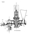
- Fig. 1 is a schematic general view of a packing-packaging machine 70 in an embodiment of the present invention.
- This packing-packaging machine 70 is a machine for manufacturing tetrahedral extraction bags 6 using an extraction bag sheet 5, which is used as a packaging sheet.
- the packing-packaging machine 70 includes: a cylindrical body 73 provided with a forming guide 72 that guides the extraction bag sheet 5; sheet feeding means (feeding rollers 74) for allowing the extraction bag sheet 5 wound around the cylindrical body 73 to run in a downward direction at a constant speed; a vertical bonding unit 75 for forming vertical bonding by welding opposite lengthwise edge portions of the extraction bag sheet 5 to each other, whereby the extraction bag sheet 5 is shaped into a tubular body 5b; a horizontal bonding unit 76 for welding and cutting the tubular body 5b, which is running downward at a constant speed, in two different directions intersecting each other as viewed from above to form first horizontal bonding and second horizontal bonding in an alternating manner; and an object dispensing unit 100 configured such that, during an alternate repetition of the formation of first horizontal bonding and the formation of second horizontal bonding, a pre
- the vertical bonding unit 75 includes an ultrasonic welding-cutting unit and also includes scrap rolling means 77 for rolling an unnecessary edge portion (selvage portion) generated when the vertical bonding is formed.
- the horizontal bonding unit 76 includes one ultrasonic welding-cutting unit configured such that its welding-cutting direction is changed oscillatingly by a predetermined angle (preferably 90°) around the axis L1 of the tubular body 5b of the extraction bag sheet 5 each time after horizontal bonding is formed.
- the ultrasonic welding-cutting unit is moved so as to be located at positions shown by solid and dotted lines in Fig. 1 in an alternating manner.
- the ultrasonic welding-cutting unit includes: an ultrasonic horn 76a having a tapered protruding end and used as a bonding head; a columnar anvil 76b; and a pressing member 78 for flattening the tubular body of the extraction bag sheet 5 when horizontal bonding is formed.
- the pressing member 78 has a width corresponding to the width of horizontal bonding to be formed.
- the pressing member 78 advances to a position on the axis L1, flattens the tubular body 5b of the extraction bag sheet 5 at positions above and below the bonding head 76a, and is moved downwardly together with the tubular body 5b of the extraction bag sheet 5.
- the pressing member 78 is moved to a return position at which the downward running distance of the tubular body 5b of the extraction bag sheet 5 during the formation of the horizontal bonding is cancelled.
- the bonding head 76a has a tapered protruding end and is of a so-called traveling type in which the head travels so that bonding can be formed to any desired length.
- the use of the traveling-type bonding head allows a reduction in its size and weight. Therefore, the bonding head can be easily driven at fast speed, and the driving mechanism therefor can be made compact.
- the bonding head 76a With the tubular body 5b of the extraction bag sheet 5 flattened with the pressing member 78, the bonding head 76a abuts against the tubular body 5b and travels in the width direction of the flattened tubular body 5b and also in a downward direction. In this manner, horizontal bonding is formed without stopping the downwardly running tubular body 5b, while the running speed of the tubular body 5b is maintained constant. After formation of the horizontal bonding, the bonding head 76a is moved to a return position at which the downward running distance of the tubular body 5b during the formation of the horizontal bonding is cancelled.
- the overall movement of the bonding head 76a is such that when the first horizontal bonding is formed, the bonding head 76a is moved obliquely downwardly as shown by an arrow a as a result of a combination of the above widthwise movement and the above downward movement.
- the bonding head 76a is moved upwardly so as to cancel the downward running distance of the tubular body 5b of the extraction bag sheet 5 during the formation of the first horizontal bonding and is rotated 90° about the axis L1 to a return position, as shown by an arrow b.
- the bonding head 76a is moved obliquely downwardly as shown by an arrow c to form second horizontal bonding in a manner similar to the formation of the first horizontal bonding and then moved to another return position, as shown by an arrow d.
- the anvil 76b does not travel in the horizontal direction during the formation of horizontal bonding but travels in the vertical direction in synchronization with the bonding head 76a. More specifically, as shown in Fig. 1 , the anvil 76b is moved downwardly together with the tubular body 5b of the extraction bag sheet 5 as shown by an arrow a' when the first horizontal bonding is formed. Then the anvil 76b first moves back to a position at which the anvil 76b is prevented from being in contact with the tubular body 5b. During this movement, the anvil 76b is moved upwardly so as to cancel the downward running distance during the formation of the first horizontal bonding and is rotated 90° about the axis L1 to a return position, as shown by an arrow b'.
- the anvil 76b advances to a position on the axis L1, is moved downwardly as shown by an arrow c' during the formation of second horizontal bonding and then moved to another return position, as shown by an arrow d'. Then the formation of first horizontal bonding and the formation of second horizontal bonding are repeated.
- the tubular body 5b of the extraction bag sheet 5 can be continuously fed during the formation of horizontal bonding without causing intermittent movement. Therefore, the production rate of extraction bags can be improved.
- the above movement of the horizontal bonding unit 76 can be achieved by driving a cam mechanism and a link mechanism using a servo motor.
- the running speeds of the bonding head 76a, the columnar anvil 76b, and the pressing member 78, when they are in contact with the tubular body 5b are preferably controlled so as to be the same as the running speed of the tubular body 5b of the extraction bag sheet 5. This can avoid the pulsation of the running speed of the tubular body 5b of the extraction bag sheet 5 and the meandering thereof, so that regularly shaped tetrahedral extraction bags 6 can be manufactured.
- Thermal welding-cutting units may be used instead of the ultrasonic welding-cutting units used in the vertical bonding unit 75 and the horizontal bonding unit 76.
- the object dispensing unit 100 is configured such that while the formation of first horizontal bonding and the formation of second horizontal bonding are repeated in an alternating manner, the object to be packaged, such as tea leaves, is packed into bag bodies of the extraction bag sheet 5 that are formed through the formation of the horizontal bonding. As shown in Figs.
- the object dispensing unit 100 includes: the hopper 101 for storing the object to be packaged such as tea leaves; the measures 102 for dispensing a predetermined amount of the object; the intermediate hopper 104 for temporarily storing the object fed from a measure 102; and the chute pipe 106 extending from the discharge hole of the intermediate hopper 104 to a position just above the pressing member 78 of the horizontal bonding unit 76.
- the measures 102 are formed by drilling cylindrical holes in a rotary table 110 at regular intervals in the circumferential direction thereof as shown in Fig. 2 , and a measure shutter 103 is provided on the bottom of each measure 102 so that the discharge hole thereof is opened and closed.
- the rotary table 110 is rotated about an axis L2 at a constant speed in the direction of an arrow.
- this measure 102 closed by its measure shutter 103 is filled with the object to be packaged, such as tea leaves, and an excess portion of the object over the measure is removed by a strickle 111, so that a predetermined amount of the object into a single bag is measured into the measure.
- a shutter opening-closing unit 120 opens the measure shutter 103
- the predetermined amount of the object in the measure 102 falls by its own weight into the intermediate hopper 104.
- the strickle 111 is attached such that its position is adjustable upward and downward, so that the gap d between the strickle 111 and the measures 102 can be adjusted according to the grain size of the object to be packaged, such as tea leaves.
- the object remaining on the rotary table 110 is collected into measures 102 by sweeping plates 112 and is used as a part of the object to be subsequently dropped by its own weight.
- the present invention is characterized in that the measure shutters 103 are controlled to open and close in the following manner.
- a predetermined amount of the object measured into a next measure starts falling.
- predetermined amounts of the object fall through the chute pipe 106 (a falling path) one after another. Therefore, a plurality of measured portions of the object can be present in the chute pipe simultaneously.
- the measure shutters 103 are opened and closed at fast speed such that the plurality of measured portions are dropped at intervals.
- the object to be packaged can be packed and packaged at a faster rate than conventional rates, so that the production rate of extraction bags can be increased. For example, when 200 extraction bags are produced per minute, the packing-packaging time for one bag is 0.3 seconds. By fully opening a closed measure shutter 103 in about 0.03 seconds, such high-speed packing-packaging can be achieved, as described later.
- Fig. 4 is a view taken in the direction of an upward
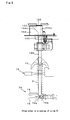
- the shutter opening-closing unit 120 includes: a rotary cam 121 that is rotated by a variable speed motor in the direction of an arrow a; a triangular plate 122 that is attached so as to be oscillatingly movable; a cylinder (not shown) for pressing the triangular plate 122 in the direction of an arrow b; an arm 123 that is reciprocated in the direction of an arrow c in response to the oscillation of the triangular plate 122; and a cam-like member 124 attached to one end of the arm 123.
- Each measure shutter 103 is attached to the rotary table 110 so as to be oscillatingly movable and has a cam follower 103a that comes in sliding contact with an end surface of the cam-like member 124.
- a spring 103b is provided so as to bias the measure shutter 103 to a position at which the discharge hole of the measure 102 is closed unless an external force is applied to the measure shutter 103.
- the rotary cam 121 when the rotary cam 121 is rotated in the direction of the arrow a, the triangular plate 122 is moved oscillatingly, so that the cam-like member 124 attached to the end of the arm 123 is reciprocated in the direction of the arrow c.
- the rotary table 110 is rotated in the direction of an arrow R at a constant speed. Therefore, when the cam follower 103a of one of the measure shutters 103 is moved to a position at which it comes into contact with the cam-like member 124, the movement of the cam-like member 124 in a direction toward the rotary table 110 causes the cam follower 103a to be pushed toward the center of the rotary table 110, whereby the measure shutter 103 is opened.
- a measure shutter 103 is opened and closed using a fixed cam provided at a position at which it comes into sliding contact with the cam follower 103a of the measure shutter
- the fixed cam must be designed such that a displacement corresponding to the distance of the reciprocal movement of the cam-like member 124 is provided within the distance corresponding to the width of the cam-like member 124.
- the pressure angle is 60° or more, and an excessive load is applied to the components. In addition, this results in an increase in power loss. Therefore, it is difficult to open and close a measure shutter 103 at high speed using such a fixed cam.
- the use of the cam-like member 124 that reciprocates as described above allows the measure shutters 103 to open and close at high speed.
- the direction of opening a measure shutter 103 (indicated by a white arrow) using the shutter opening-closing unit 120 is opposite to the running direction R of the object to be packaged (indicated by a black arrow) when the measure shutter 103 is opened (i.e., is opposite to the running direction of the measure 102 when the measure shutter 103 is opened), as shown in Fig. 5(a) .
- the shutter may be allowed to slide in one direction as described above in Fig. 5(a) .
- the shutter may be allowed to slide in opposite directions as shown in Fig. 5(b) , may be supported by a hinge so as to open in one direction as shown in Fig. 5(c) , or may be composed of hinged double doors as shown in Fig. 5(d) .
- the intermediate hopper 104 is provided to suppress the vertical spreading of the object to be packaged in the falling path when the object is dropped by its own weight into the falling path from a measure 102 formed in the rotary table 110 rotating at a constant speed.
- the intermediate hopper 104 is formed into a particular shape that can allow the horizontal velocity component of the object 85 to be minimized, and an intermediate hopper shutter 105 used as a second shutter is provided on the discharge hole of the intermediate hopper 104.
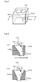
- the intermediate hopper 104 is formed such that its inner wall 104a on the upstream side in the running direction of a measure 102 (the rotation direction R of the rotary table 110) at the opening-closing position of its measure shutter 103 is a vertical wall.
- an inner wall 104b of the intermediate hopper 104 on the downstream side in the running direction of the measure 102 is preferably an inclined wall.
- the inner wall 104a of the intermediate hopper 104 on the upstream side in the running direction of the measure 102 (the rotation direction R of the rotary table 110) is formed so as to be perpendicular to the running direction R of the measure 102.
- the vertical velocity component of the object 85 dropped from the measure 102 decreases very little when the object 85 impinges on the inner wall 104a, as shown in Fig. 8(a) .
- the inner wall 104a of the intermediate hopper 104 on the upstream side in the running direction R of the measure 102 is inclined upward as shown in Fig. 8(b) , the vertical velocity component of the object 85 dropped from the measure 102 and impinging on the inner wall 104a decreases. This is not preferred because the object is likely to spread vertically in the falling path.
- the intermediate hopper 104 is formed such that its lower region 104c in which the object to be packaged is accumulated has a substantially straight shape, i.e., has a vertically extending inner wall. This allows a reduction in the discharge time required to completely discharge the object 85 that is accumulated in the intermediate hopper 104 and starts falling by its own weight when the intermediate hopper shutter 105 is opened. However, if the inner wall in the lower region is inclined, the discharge time becomes long. This is not preferable because the object falls while spreading vertically in the chute pipe 106.
- the intermediate hopper 104 is formed such that its region above the region 104c has a flat ellipsoidal or oval horizontal cross-section with a minor axis S substantially the same as the diameter of the chute pipe 106. This prevents the object fed to the chute pipe 106 through the intermediate hopper 104 from having an additional velocity component in the direction of the minor axis S, so that the vertical spreading of the object in the falling path can be suppressed.
- the intermediate hopper shutter 105 is provided so that it temporarily accumulates the object dropped by its own weight from a measure 102 formed in the rotary table rotated at a constant speed so as to eliminate the horizontal velocity component, and the object is again dropped by its own weight. Therefore, preferably, the timing of opening and closing the intermediate hopper shutter 105 is controlled in relation to the timing of opening and closing the measure shutter 103.
- the intermediate hopper 104 and the intermediate hopper shutter 105 are not required to be provided in the following cases:
- the rotary table 110 is not rotated at a constant speed but is rotated intermittently, and a measure shutter 103 is opened with the movement of the measures 102 stopped;
- the object to be packaged does not have any horizontal velocity component when a measure shutter is opened to allow the object to fall (for example, the measure shutter is opened when a measure reciprocating intermittently stops moving, as in an embodiment described later).
- the packing-packaging machine must be configured so as to have high mechanical shock resistance, and its driving power must be increased. This increases the manufacturing cost and maintenance cost of the packing-packaging machine.
- the inner wall of the chute pipe 106 is subjected to friction reducing treatment or antistatic treatment so that the resistance of the object falling through the chute pipe 106 is reduced to suppress the vertical spreading of the object in the chute pipe 106.
- friction reducing treatment include satin finishing treatment, formation of vertical grooves, and application of a friction reducing agent.
- an air inlet hole is provided in some mid portion of the chute pipe 106.
- the falling speed of a first portion of the object to be packaged is greater than the falling speed of a second portion of the object that follows the first portion of the object. Therefore, when no air inlet hole is provided, a negative pressure generated between the first and second portions of the object acts so as to reduce the spacing therebetween. In particular, the rear end of the first portion of the object is dragged, and the distance between the rear end of the first portion of the object and the front end of the second portion of the object is reduced.
- an air inlet hole is provided, the distance between the portions of the object for single bags that fall through the chute pipe 106 one after the other can be easily ensured.
- the chute pipe 106 is not necessarily disposed so as to extend from a position immediately below a measure shutter 103 or the intermediate hopper shutter 105 to a position immediately above the pressing member 78 of the horizontal bonding unit 76.
- the chute pipe 106 must be disposed so as to extend at least to a position at which the extraction bag sheet 5 is shaped into the tubular body 5b. To eliminate the possibility that the object falling through the falling path adheres to the extraction bag sheet 5 and is caught in horizontal bonding during the formation thereof, it is preferable to dispose the chute pipe 106 so as to extend to a position immediately above the formation point of the horizontal bonding.
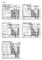
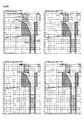
- Figs. 9A to 9D are series of diagrams illustrating the operation of the hopper 101 and the intermediate hopper 104.
- an operation angle is an angle defined by dividing one operational cycle of one of the measures 102 formed in the rotary table 110 at regular intervals into 360°.
- the vertical axes represent the distance (mm) from a midpoint between a point at which the pressing member 78 of the horizontal bonding unit 76 starts pressing the extraction bag sheet and a point at which the pressing member 78 releases the extraction bag sheet.
- the horizontal axes represent the distance (mm) from the center axis of the chute pipe 106.
- Broken lines represent the falling trajectories of the reference points (the front ends and rear ends in the falling direction) of the object 85 to be packaged.
- a measure (No. 1) 102 filled with the object 85 to be packaged is moved above the intermediate hopper 104 through the rotation of the rotary table 110, and the measure shutter 103 for the measure (No. 1) 102 is opened, whereby the object 85 is allowed to fall by its own weight and fed to the intermediate hopper 104.
- the intermediate hopper shutter 105 is in a closed state, so that the fed object 85 stays in the intermediate hopper 104 ( Figs. 9A(a), and 9A(b) ).
- the intermediate hopper shutter 105 After or shortly before the entire amount of the object 85 in the measure 102 is accumulated in the intermediate hopper 104, the intermediate hopper shutter 105 starts opening ( Fig.9A(c) ) to allow the accumulated object 85 to fall by its own weight into the chute pipe 106.
- the intermediate hopper shutter 105 is held fully open ( Figs. 9A(d) to 9C(j) ) so that the object 85 in the intermediate hopper is fully discharged.
- a next measure (No. 2) 102 is moved above the intermediate hopper 104 ( Figs. 9A(c), (d), and (e) ).
- the measure shutter 103 for the next measure starts opening ( Fig. 9B(g) ) and fully opens ( Fig. 9B(h) ).
- the object 85 in the measure (No. 2) 102 falls through the opened measure shutter 103 into the intermediate hopper 104 ( Fig.9B(i) ).
- the closing operation of the intermediate hopper shutter 105 is completed ( Fig. 9C(k) ), and the object 85 is again accumulated in the intermediate hopper 104. While the object 85 from the measure (No.2) comes close to a predetermined position, the measure shutter 103 for the next measure starts opening ( Fig. 9B(g) ) and fully opens ( Fig. 9B(h) ).
- the object 85 in the measure (No. 2) 102 falls through the opened measure shutter 103 into the intermediate hopper 104 ( Fig.9B(i) ).
- the closing operation of the intermediate hopper shutter 105 is completed ( Fig. 9C(k) ), and the object 85 is again accumulated in the intermediate hopper
- Fig. 10 is a diagram showing the relationship between time and the positions of the object 85 falling in the chute pipe 106 in the manner described above.
- the measure shutter 103 and the intermediate hopper shutter 105 are opened in a short time (about 0.03 seconds) to feed the object 85 for a first bag measured by the measure 102 into the chute pipe 106.
- the object 85 for a second bag is fed into the chute pipe 106 before horizontal bonding for the first bag packed with the object 85 is completed (more specifically, the falling path of the object for the first bag is closed by the pressing member 78).
- the object for the first bag and the object for the second bag fall through the chute pipe 106 with a spacing therebetween. Therefore, with the packing-packaging machine 70, the period of time after the object 85 to be packaged is fed into the chute pipe 106 until a bag body is packed with the object 85 is not rate-limiting, and this does not cause a reduction in production rate of extraction bags.
- the extraction bag sheet 5 sent to the packing-packaging machine 70 may be any of various types of long sheets of woven or nonwoven fabric for manufacturing extraction bags and laminates thereof, and string tags may be attached thereto, if necessary.
- any string formed of an ultrasonically weldable or thermally weldable material including thermoplastic synthetic fiber such as polypropylene or polyethylene may be used.
- Any tag formed from paper, a plastic sheet, or the like may be used.
- a water-permeable filter sheet is used. Examples of the water-permeable filter sheet include paper, films having a large number of holes, and woven and nonwoven fabrics formed of single or conjugated fibers selected from synthetic fibers such as polyester, nylon, polyethylene, and polypropylene, semisynthetic fibers such as rayon, and natural fibers such as paper mulberry and edgeworthia chrysantha.
- Tags and a string may be or may not be attached to the water-permeable filter sheet, and no particular limitation is imposed on the arrangement of the tags and the sting on the water-permeable filter sheet.
- An extraction bag sheet 5 wound into a roll may be used.
- the packing-packaging machine 70 of the present invention may be used in combination with any machine for manufacturing an extraction bag sheet by attaching a hanging string and tags to a water-permeable filter sheet that forms the extraction bag sheet.
- the packing-packaging machine of the present invention can be implemented in various embodiments, in addition to the above embodiment.
- the object dispensing unit in the packing-packaging machine is not limited to a unit that uses measures formed in a rotary table.
- an object dispensing unit 100B shown in Fig. 11 may be used.
- This object dispensing unit 100B includes a pair of measures 102B (a first measure 102i and a second measure 102ii) disposed below a hopper 101 for storing the object 85 to be packaged, such as tea leaves.
- the pair of measures 102B is intermittently reciprocated between a left end position shown in Fig. 11(a) and a right end position shown in Fig. 11(b) on a base 130 by a link mechanism 132 driven by a variable speed motor 131.
- a set shutter 133 for opening and closing the bottom of the measure 102i or 102ii at predetermined timing is slidably fit into the base 130 of the object dispensing unit 100B, and a chute pipe 106 extends from a position directly below the set shutter 133 toward a horizontal bonding unit (not shown).
- Fig. 12 is a timing chart showing the positions of the first and second measures 102i and 102ii, the open-close state of the set shutter 133, and the packed states of the first and second measures 102i and 102ii with the object to be packaged.
- the first measure 102i When the pair of measures 102B is located at the left end position of its reciprocal movement, the first measure 102i is located below the left discharge hole 101a of the hopper and fully filled with the object 85 to be packaged.
- the pair of measures 102B starts moving rightward with the second measure 102ii located above the chute pipe 106 and being empty (0 seconds).
- the movement of the pair of measures 102B is stopped, and the operation of filling the second measure 102ii with the object 85 is started.
- the set shutter 133 starts opening (0.09 seconds), and the object 85 in the first measure 102i starts falling.
- the set shutter 133 After the set shutter 133 fully opens (0.12 seconds) and while the object 85 from the first measure 102i is falling, the second measure 102ii is fully filled with the object 85 (0.21 seconds). After the first measure 102i is emptied (0.24 seconds), the set shutter 133 starts closing. When the set shutter 133 is fully closed, the pair of measures 102B starts moving leftward (0.3 seconds) and stops moving when the first measure 102i is located below the left discharge hole 101a of the hopper and the second measure 102ii is located above the set shutter 133. Then the operation of filling the first measure 102i with the object 85 is started. At the same time, the set shutter 133 starts opening (0.39 seconds), and the object 85 starts falling from the second measure 102ii. At this point, the object 85 that has fallen from the first measure 102i is still falling through the chute pipe 106 (see Fig. 10 ).
- the set shutter 133 When the set shutter 133 is fully opened (0.42 seconds) and while the object 85 from the second measure 102ii is falling, the first measure 102i is fully filled with the object 85 (0.51 seconds). After the second measure 102ii is emptied (0.54 seconds), the set shutter 133 starts closing (0.57 seconds). After the set shutter 133 is fully closed, the pair of measures 102B again starts moving rightward. Then the above operation is repeated, and the object falls from the first and second measures 102i and 102ii into the chute pipe 106 in an alternating manner.
- this object dispensing unit 100B before completion of the formation of horizontal bonding on a bag body packed with the object for a first bag that has fallen during the opening-closing operation of the set shutter 133, the object for a second bag that has been measured into a next measure starts falling. Therefore, high-speed packing operation can be achieved.
- the measures 102i and 102ii are in a stationary state when the object 85 starts falling from one of the measures 102i and 102ii and until the measure is emptied, so that the falling object does not have a horizontal velocity component and therefore falls straightly downward. Therefore, in the object dispensing unit 100B, the intermediate hopper 104 described above is not required.
- the packing-packaging machine of the present invention can be implemented in other various modes. For example, a predetermined amount of the object for a single bag may be measured with a measure and may be measured with a computerized scale. A packet conveyer may be used to transfer the object for a single bag to the opening-closing position of the shutter.
- the object is not limited to be dropped by its own weight into a bag body by the opening-closing operation of the shutter.
- the object may be allowed to fall with an initial velocity imparted thereto.
- Two ultrasonic welding-cutting units provided such that their ultrasonic welding-cutting directions interest each other as viewed from above may be used as the horizontal bonding unit 76 to manufacture tetrahedral extraction bags.
- a welding-cutting unit having a single bonding direction that is not changed in an alternating manner may be used as the horizontal bonding unit 76 to manufacture flat extraction bags.
- a so-called direct pressing type bonding head having an end width corresponding to the bonding width of an object to be bonded may be used as the bonding head of the horizontal bonding unit 76.
- the object for a next single bag is fed into the chute pipe 106.
- a thermal welding unit may be used, or an ultrasonic welding-cutting unit may be used.
- the packing-packaging machine is not required to include the vertical bonding unit.
- the object to be packaged that is packed using the packing-packaging machine of the present invention is not limited to tea leaves for black teas, green teas, herbal teas, and other teas.
- Other examples of the object include dried small sardine, dried bonito, and other various powdery and granular material.
- the packing-packaging machine of the present invention is useful for continuously manufacturing tea bags for black teas, green teas, herbal teas, and other teas and extraction bags containing dried products such as dried small sardine and dried bonito for preparing stock at high speed in a production line.
Landscapes
- Engineering & Computer Science (AREA)
- Mechanical Engineering (AREA)
- Containers And Plastic Fillers For Packaging (AREA)
- Basic Packing Technique (AREA)
- Supplying Of Containers To The Packaging Station (AREA)
Description
- The present invention relates to a packing-packaging method and machine for forming a packaging sheet into bags and packing the bags with an object to be packaged.
- Commonly used extraction bags include tea bags for black teas, green teas, herbal teas, and other teas and extraction bags containing dried material such as dried small sardine and dried bonito for preparing stock. Such an extraction bag includes a tetrahedral or rectangular bag body formed from a water-permeable filter extraction bag sheet such as a nonwoven fabric sheet, and an extractable material, such as tea leaves, packed in the bag body. If necessary, a hanging string with a tag is attached to the outer surface of the bag body.
- Such extraction bags, specifically tetrahedral extraction bags with strings and tags, for example, can be manufactured as follows. An extraction bag sheet prepared by disposing tags and a string used as a hanging string on a strip-like water-permeable filter sheet is shaped into a tubular form by bonding the opposite end portions of the extraction bag sheet to each other. Then the formation of first horizontal bonding by flattening, welding, and cutting the tubular body in a first width direction and the formation of second horizontal bonding by welding and cutting the cut tubular body in a second width direction intersecting the first width direction are performed alternately. An extractable material, such as tea leaves, is packed between the formation of the first bonding and the formation of the second bonding (
Patent Documents 1 and 2). - In one exemplary method of packing such bags with an extractable material, an auger screw attached inside a packing pipe for supplying the extractable material from a hopper to a bag body is rotated to supply a predetermined amount of the extractable material to the bag body (Patent Document 3). In another exemplary method, an extractable material stored in a hopper is measured with measures formed in a rotary table and is supplied to a bag body through a chute pipe (Patent Document 4).
-
US 2008/091299 A1 discloses a weighing and packaging system including a weighing unit, a packaging unit, a dropping path, a display unit, a determination unit and a display control unit. The dropping path is disposed between the weighing unit and the packaging unit. The display unit includes a display screen to display an image representing the weighing unit, the dropping path and the packaging unit. The determination unit is configured to determine whether the articles are present in the weighing unit, the dropping path, and the packaging unit, respectively. The display control unit is configured to display an indicator indicative of the articles on the image representing the weighing unit, the dropping path and the packaging unit displayed on the display screen according to a determination result by the determination unit. -
WO 97/02179 A1 - [Patent Document 1] Published Japanese Translation of
PCT International Application No. 2001-519729 - [Patent Document 2] Published Japanese Translation of
PCT International Application No. 2006-510550 - [Patent Document 3] Japanese Patent Application Laid-Open No.
2003-237701 2002-46704 - However, with the packing method using an auger screw, when tea leaves are packed, they can be undesirably pulverized.
- In the packing method using measures, one measure is disposed above a bonding unit for producing a bag, and the measure and the bonding unit are connected through a chute pipe. The tea leaves measured into the measure are dropped through the chute pipe into a bag body to pack it with the tea leaves, and horizontal bonding is formed to seal the bag body, whereby an extraction bag is obtained. After completion of the formation of the horizontal bonding, the tea leaves are again dropped in a similar manner. The process of dropping the tea leaves and forming the horizontal bonding is repeated to produce extraction bags one after the other. Therefore, in the conventional packing method using measures, it is difficult to improve the production rate because the period of time after the tea leaves are fed into the chute pipe until the falling tea leaves reach a bag body is rate-limiting. For example, unfortunately, only about 50 to 100 tea bags can be produced per minute.
- In view of the foregoing, it is an object of the present invention to enable an object such as tea leaves to be packed and packaged in bag bodies formed from a packaging sheet at high speed without pulverization of the object.
- The present inventor has found the following facts. (i) In a process of dropping an object for a single bag into a bag body through a chute pipe or the like to pack the bag body with the object and forming horizontal bonding to package the object, the rate of packing-packaging can be drastically improved by allowing the object for a plurality of bags to be present in the chute pipe. This state can be created by dropping the object for a first bag and then dropping the object for a second bag before the packaging of the dropped object for the first bag is completed. (ii) The falling-direction front end of the object falling by its own weight does not reach a bag body at a time earlier than the time computed using the gravitational acceleration because of, for example, friction with respect to the chute pipe and the like, and the rearmost end of the falling object reaches the bag body at a later time. When the entire portion of the object for a single bag is dropped all together, the vertical spreading of the object during falling is determined substantially constantly, depending on the properties of the object such as grain size, shape, and weight, the inner diameter and inner surface roughness of the chute pipe, and other factors. (iii) The packing-packaging state described in (i) can be achieved by the following manner. The object is dropped using a shutter that opens at high speed so that the vertical spreading of the falling object is minimized. In addition, the opening-closing timing of the shutter and the timing of the formation of horizontal bonding are controlled such that a falling path is closed with a pressing member or a bonding head for forming the horizontal bonding after the rearmost end of the falling object passes through the position for forming the horizontal bonding. In this manner, the rate of packing-packaging can be drastically improved.
- Accordingly, the present invention provides a packing-packaging machine comprising:
- a horizontal bonding unit for forming bonding at predetermined intervals on a tubular body formed from a packaging sheet to thereby form a bag body, the bonding being formed in a direction of a width of the tubular body (the bonding hereinafter being referred to as horizontal bonding); and
- an object dispensing unit for, during a repetition of formation of the horizontal bonding, dropping a predetermined amount of an object to be packaged, into the bag body to pack the bag body with the object, wherein
- the object dispensing unit comprises a shutter for opening and closing a falling path of the predetermined amount of the object into the bag body, and the shutter is opened and closed such that the predetermined amount of the object and another predetermined amount of the object fall with a spacing therebetween, and that before the horizontal bonding is formed on the bag body packed with the predetermined amount of the object which has been dropped during opening-closing operation of the shutter, the other predetermined amount of the object for a next bag body starts falling.
- The present invention also provides a method for packing and packaging an object to be packaged, the method comprising: forming horizontal bonding at predetermined intervals on a tubular body of a packaging sheet to thereby form a bag body; and, during a repetition of formation of the horizontal bonding, dropping a predetermined amount of the object into the bag body to pack the bag body with the object, wherein
a falling path of the predetermined amount of the object into the bag body is opened and closed using a shutter, and the shutter is opened and closed such that the predetermined amount of the object and another predetermined amount of the object fall with a spacing therebetween, and that before the horizontal bonding is formed on the bag body packed with the predetermined amount of the object which has been dropped during opening-closing operation of the shutter, the other predetermined amount of the object for a next bag body starts falling. - In the packing-packaging machine and method of the present invention, a predetermined amount of an object to be packaged is dropped into a bag body by opening and closing the shutter to pack the bag body with the object. This can eliminate the problem of pulverization of the object that occurs when the object is tea leaves and an auger screw is used.
- Moreover, after a predetermined amount of the object is dropped into a bag body by opening and closing the shutter and before horizontal bonding is formed on the bag body packed with the predetermined amount of the object, another predetermined amount of the object for a next bag body is dropped. Therefore, the packing-packaging rate of bag bodies is not limited by the period of time after a predetermined amount of the object starts falling until it reaches a bag body. Accordingly, the packing-packaging rate of bag bodies can be drastically improved. For example, 200 or more tea bags can be produced per minute.
-
-
Fig. 1 is a schematic general view of a packing-packaging machine. -
Fig. 2 is a horizontal cross-sectional view showing the vicinity of measures of the packing-packaging machine. -
Fig. 3A is a vertical cross-sectional view showing the vicinity of a shutter opening-closing unit of the packing-packaging machine. -
Fig. 3B is a vertical cross-sectional view showing the vicinity of sweeping plates of the packing-packaging machine. -
Fig. 4 is a view taken in the direction of an arrow, showing the shutter opening-closing unit. -
Fig. 5 is a set of diagrams illustrating the manners of opening a measure shutter. -
Fig. 6 is a view taken in the direction of an arrow, showing the vicinity of an intermediate hopper shutter. -
Fig. 7 is a perspective view of an intermediate hopper. -
Fig. 8 is a set of cross-sectional views of intermediate hoppers. -
Fig. 9A is a series of diagrams illustrating the operation of an object dispensing unit. -
Fig. 9B is a series of diagrams illustrating the operation of the object dispensing unit. -
Fig. 9C is a series of diagrams illustrating the operation of the object dispensing unit. -
Fig. 9D is a series of diagrams illustrating the operation of the object dispensing unit. -
Fig. 9E is a diagram illustrating the operation of the object dispensing unit. -
Fig. 10 is a diagram illustrating the dropping states of an object to be packaged inside a chute pipe. -
Fig. 11 is a set of cross-sectional views of an object dispensing unit. -
Fig. 12 is a timing chart for the object dispensing unit shown inFig. 11 . -
- 5
- extraction bag sheet
- 5b
- tubular body
- 6
- extraction bag
- 70
- packing-packaging machine
- 72
- forming guide
- 73
- cylindrical body
- 74
- feeding roller
- 75
- vertical bonding unit
- 76
- horizontal bonding unit
- 76a
- bonding head (ultrasonic horn)
- 76b
- anvil
- 77
- scrap rolling means
- 78
- pressing member
- 85
- object to be packaged
- 100, 100B
- object dispensing unit
- 101
- hopper
- 102
- measure
- 102B
- pair of measures
- 103
- measure shutter
- 103a
- cam follower
- 103b
- spring
- 104
- intermediate hopper
- 104a
- inner wall
- 104b
- inner wall
- 104c
- region
- 105
- intermediate hopper shutter
- 106
- chute pipe
- 110
- rotary table
- 111
- strickle
- 112
- sweeping plate
- 120
- shutter opening-closing unit
- 121
- rotary cam
- 122
- triangular plate
- 123
- arm
- 124
- cam-like member
- 130
- base
- 131
- variable speed motor
- 132
- link mechanism
- 133
- set shutter
- L1
- axis of tubular body of extraction bag sheet
- L2
- rotation axis
- Hereinafter, the present invention will be specifically described with reference to the drawings. In the drawings, the same reference numerals denote the same or similar elements.
-
Fig. 1 is a schematic general view of a packing-packagingmachine 70 in an embodiment of the present invention. - This packing-packaging
machine 70 is a machine for manufacturingtetrahedral extraction bags 6 using anextraction bag sheet 5, which is used as a packaging sheet. In general, the packing-packagingmachine 70 includes: acylindrical body 73 provided with a formingguide 72 that guides theextraction bag sheet 5; sheet feeding means (feeding rollers 74) for allowing theextraction bag sheet 5 wound around thecylindrical body 73 to run in a downward direction at a constant speed; avertical bonding unit 75 for forming vertical bonding by welding opposite lengthwise edge portions of theextraction bag sheet 5 to each other, whereby theextraction bag sheet 5 is shaped into atubular body 5b; ahorizontal bonding unit 76 for welding and cutting thetubular body 5b, which is running downward at a constant speed, in two different directions intersecting each other as viewed from above to form first horizontal bonding and second horizontal bonding in an alternating manner; and anobject dispensing unit 100 configured such that, during an alternate repetition of the formation of first horizontal bonding and the formation of second horizontal bonding, a predetermined amount of tea leaves or a similar product, which are used as the contents of an extraction bag and supplied from ahopper 101, is measured into ameasure 102 and dropped into achute pipe 106 through anintermediate hopper 104 to thereby pack the tubular body of theextraction bag sheet 5 with the tea leaves or a similar product. - The
vertical bonding unit 75 includes an ultrasonic welding-cutting unit and also includes scrap rolling means 77 for rolling an unnecessary edge portion (selvage portion) generated when the vertical bonding is formed. - The
horizontal bonding unit 76 includes one ultrasonic welding-cutting unit configured such that its welding-cutting direction is changed oscillatingly by a predetermined angle (preferably 90°) around the axis L1 of thetubular body 5b of theextraction bag sheet 5 each time after horizontal bonding is formed. The ultrasonic welding-cutting unit is moved so as to be located at positions shown by solid and dotted lines inFig. 1 in an alternating manner. The ultrasonic welding-cutting unit includes: anultrasonic horn 76a having a tapered protruding end and used as a bonding head; acolumnar anvil 76b; and a pressingmember 78 for flattening the tubular body of theextraction bag sheet 5 when horizontal bonding is formed. - The pressing
member 78 has a width corresponding to the width of horizontal bonding to be formed. When horizontal bonding is formed, the pressingmember 78 advances to a position on the axis L1, flattens thetubular body 5b of theextraction bag sheet 5 at positions above and below thebonding head 76a, and is moved downwardly together with thetubular body 5b of theextraction bag sheet 5. After formation of the horizontal bonding, the pressingmember 78 is moved to a return position at which the downward running distance of thetubular body 5b of theextraction bag sheet 5 during the formation of the horizontal bonding is cancelled. - The
bonding head 76a has a tapered protruding end and is of a so-called traveling type in which the head travels so that bonding can be formed to any desired length. The use of the traveling-type bonding head allows a reduction in its size and weight. Therefore, the bonding head can be easily driven at fast speed, and the driving mechanism therefor can be made compact. - With the
tubular body 5b of theextraction bag sheet 5 flattened with the pressingmember 78, thebonding head 76a abuts against thetubular body 5b and travels in the width direction of the flattenedtubular body 5b and also in a downward direction. In this manner, horizontal bonding is formed without stopping the downwardly runningtubular body 5b, while the running speed of thetubular body 5b is maintained constant. After formation of the horizontal bonding, thebonding head 76a is moved to a return position at which the downward running distance of thetubular body 5b during the formation of the horizontal bonding is cancelled. - Therefore, the overall movement of the
bonding head 76a is such that when the first horizontal bonding is formed, thebonding head 76a is moved obliquely downwardly as shown by an arrow a as a result of a combination of the above widthwise movement and the above downward movement. After formation of the first horizontal bonding, thebonding head 76a is moved upwardly so as to cancel the downward running distance of thetubular body 5b of theextraction bag sheet 5 during the formation of the first horizontal bonding and is rotated 90° about the axis L1 to a return position, as shown by an arrow b. Next, thebonding head 76a is moved obliquely downwardly as shown by an arrow c to form second horizontal bonding in a manner similar to the formation of the first horizontal bonding and then moved to another return position, as shown by an arrow d. - The
anvil 76b does not travel in the horizontal direction during the formation of horizontal bonding but travels in the vertical direction in synchronization with thebonding head 76a. More specifically, as shown inFig. 1 , theanvil 76b is moved downwardly together with thetubular body 5b of theextraction bag sheet 5 as shown by an arrow a' when the first horizontal bonding is formed. Then theanvil 76b first moves back to a position at which theanvil 76b is prevented from being in contact with thetubular body 5b. During this movement, theanvil 76b is moved upwardly so as to cancel the downward running distance during the formation of the first horizontal bonding and is rotated 90° about the axis L1 to a return position, as shown by an arrow b'. Next, theanvil 76b advances to a position on the axis L1, is moved downwardly as shown by an arrow c' during the formation of second horizontal bonding and then moved to another return position, as shown by an arrow d'. Then the formation of first horizontal bonding and the formation of second horizontal bonding are repeated. - By moving the
bonding head 76a and theanvil 76b in the manner described above, thetubular body 5b of theextraction bag sheet 5 can be continuously fed during the formation of horizontal bonding without causing intermittent movement. Therefore, the production rate of extraction bags can be improved. - The above movement of the
horizontal bonding unit 76 can be achieved by driving a cam mechanism and a link mechanism using a servo motor. In such a case, the running speeds of thebonding head 76a, thecolumnar anvil 76b, and the pressingmember 78, when they are in contact with thetubular body 5b, are preferably controlled so as to be the same as the running speed of thetubular body 5b of theextraction bag sheet 5. This can avoid the pulsation of the running speed of thetubular body 5b of theextraction bag sheet 5 and the meandering thereof, so that regularly shapedtetrahedral extraction bags 6 can be manufactured. - Thermal welding-cutting units may be used instead of the ultrasonic welding-cutting units used in the
vertical bonding unit 75 and thehorizontal bonding unit 76. - In the packing-packaging
machine 70, theobject dispensing unit 100 is configured such that while the formation of first horizontal bonding and the formation of second horizontal bonding are repeated in an alternating manner, the object to be packaged, such as tea leaves, is packed into bag bodies of theextraction bag sheet 5 that are formed through the formation of the horizontal bonding. As shown inFigs. 2 ,3A , and3B , theobject dispensing unit 100 includes: thehopper 101 for storing the object to be packaged such as tea leaves; themeasures 102 for dispensing a predetermined amount of the object; theintermediate hopper 104 for temporarily storing the object fed from ameasure 102; and thechute pipe 106 extending from the discharge hole of theintermediate hopper 104 to a position just above the pressingmember 78 of thehorizontal bonding unit 76. - The
measures 102 are formed by drilling cylindrical holes in a rotary table 110 at regular intervals in the circumferential direction thereof as shown inFig. 2 , and ameasure shutter 103 is provided on the bottom of eachmeasure 102 so that the discharge hole thereof is opened and closed. The rotary table 110 is rotated about an axis L2 at a constant speed in the direction of an arrow. When one of themeasures 102 is placed below thehopper 101 during the rotation of the rotary table 110, thismeasure 102 closed by itsmeasure shutter 103 is filled with the object to be packaged, such as tea leaves, and an excess portion of the object over the measure is removed by astrickle 111, so that a predetermined amount of the object into a single bag is measured into the measure. When a shutter opening-closing unit 120 opens themeasure shutter 103, the predetermined amount of the object in themeasure 102 falls by its own weight into theintermediate hopper 104. Thestrickle 111 is attached such that its position is adjustable upward and downward, so that the gap d between thestrickle 111 and themeasures 102 can be adjusted according to the grain size of the object to be packaged, such as tea leaves. After the object in ameasure 102 is dropped by its own weight, the object remaining on the rotary table 110 is collected intomeasures 102 by sweepingplates 112 and is used as a part of the object to be subsequently dropped by its own weight. - The present invention is characterized in that the
measure shutters 103 are controlled to open and close in the following manner. Before completion of horizontal bonding on a bag body packed with a predetermined amount of the object dropped during the opening-closing operation of one of the shutters, a predetermined amount of the object measured into a next measure starts falling. In this case, predetermined amounts of the object fall through the chute pipe 106 (a falling path) one after another. Therefore, a plurality of measured portions of the object can be present in the chute pipe simultaneously. Themeasure shutters 103 are opened and closed at fast speed such that the plurality of measured portions are dropped at intervals. In this manner, the object to be packaged can be packed and packaged at a faster rate than conventional rates, so that the production rate of extraction bags can be increased. For example, when 200 extraction bags are produced per minute, the packing-packaging time for one bag is 0.3 seconds. By fully opening aclosed measure shutter 103 in about 0.03 seconds, such high-speed packing-packaging can be achieved, as described later. - However, when the opening speed of the
measure shutters 103 is low, the falling object to be packaged spreads vertically in thechute pipe 106. Therefore, it is difficult to ensure a sufficient spacing between the predetermined amounts of the falling object. - E pointing to the rotary table 110, illustrating the shutter opening-
closing unit 120 suitable for opening and closing themeasure shutters 103 at high speed in the manner described above. The shutter opening-closing unit 120 includes: arotary cam 121 that is rotated by a variable speed motor in the direction of an arrow a; atriangular plate 122 that is attached so as to be oscillatingly movable; a cylinder (not shown) for pressing thetriangular plate 122 in the direction of an arrow b; anarm 123 that is reciprocated in the direction of an arrow c in response to the oscillation of thetriangular plate 122; and a cam-like member 124 attached to one end of thearm 123. Eachmeasure shutter 103 is attached to the rotary table 110 so as to be oscillatingly movable and has acam follower 103a that comes in sliding contact with an end surface of the cam-like member 124. Aspring 103b is provided so as to bias themeasure shutter 103 to a position at which the discharge hole of themeasure 102 is closed unless an external force is applied to themeasure shutter 103. - In the shutter opening-
closing unit 120, when therotary cam 121 is rotated in the direction of the arrow a, thetriangular plate 122 is moved oscillatingly, so that the cam-like member 124 attached to the end of thearm 123 is reciprocated in the direction of the arrow c. The rotary table 110 is rotated in the direction of an arrow R at a constant speed. Therefore, when thecam follower 103a of one of themeasure shutters 103 is moved to a position at which it comes into contact with the cam-like member 124, the movement of the cam-like member 124 in a direction toward the rotary table 110 causes thecam follower 103a to be pushed toward the center of the rotary table 110, whereby themeasure shutter 103 is opened. Then, when the cam-like member 124 moves in a direction away from the rotary table 110, the action of thespring 103b causes themeasure shutter 103 to close. Therefore, the cam-like member 124 moving reciprocally allows themeasure shutters 103 to open and close. - If a
measure shutter 103 is opened and closed using a fixed cam provided at a position at which it comes into sliding contact with thecam follower 103a of the measure shutter, the fixed cam must be designed such that a displacement corresponding to the distance of the reciprocal movement of the cam-like member 124 is provided within the distance corresponding to the width of the cam-like member 124. In this case, the pressure angle is 60° or more, and an excessive load is applied to the components. In addition, this results in an increase in power loss. Therefore, it is difficult to open and close ameasure shutter 103 at high speed using such a fixed cam. However, the use of the cam-like member 124 that reciprocates as described above allows themeasure shutters 103 to open and close at high speed. - Preferably, the direction of opening a measure shutter 103 (indicated by a white arrow) using the shutter opening-
closing unit 120 is opposite to the running direction R of the object to be packaged (indicated by a black arrow) when themeasure shutter 103 is opened (i.e., is opposite to the running direction of themeasure 102 when themeasure shutter 103 is opened), as shown inFig. 5(a) . It is not preferable to set the direction of opening themeasure shutter 103 to be the same as the running direction of the object to be packaged because the size of the inlet opening of thechute pipe 106 or the inlet opening of theintermediate hopper 104 must be increased accordingly. - In the present invention, no particular limitation is imposed on the manner of opening and closing the shutter to drop the predetermined amount of the object to be packaged into the falling path therefor formed from the
intermediate hopper 104, thechute pipe 106, and the like. The shutter may be allowed to slide in one direction as described above inFig. 5(a) . In addition, the shutter may be allowed to slide in opposite directions as shown inFig. 5(b) , may be supported by a hinge so as to open in one direction as shown inFig. 5(c) , or may be composed of hinged double doors as shown inFig. 5(d) . To simplify the opening-closing mechanism for the shutter, it is preferable to slide the shutter in one direction as shown inFig. 5(a) . - The
intermediate hopper 104 is provided to suppress the vertical spreading of the object to be packaged in the falling path when the object is dropped by its own weight into the falling path from ameasure 102 formed in the rotary table 110 rotating at a constant speed. Theintermediate hopper 104 is formed into a particular shape that can allow the horizontal velocity component of theobject 85 to be minimized, and anintermediate hopper shutter 105 used as a second shutter is provided on the discharge hole of theintermediate hopper 104. - Preferably, as shown in
Fig. 6 (a view taken by an arrow in D direction inFig. 2 ),Fig. 7 (a perspective view of the intermediate hopper 104), andFig. 8(a) (a cross-sectional view ofFig. 7 ), theintermediate hopper 104 is formed such that its inner wall 104a on the upstream side in the running direction of a measure 102 (the rotation direction R of the rotary table 110) at the opening-closing position of itsmeasure shutter 103 is a vertical wall. In addition, aninner wall 104b of theintermediate hopper 104 on the downstream side in the running direction of themeasure 102 is preferably an inclined wall. - As described above, the inner wall 104a of the
intermediate hopper 104 on the upstream side in the running direction of the measure 102 (the rotation direction R of the rotary table 110) is formed so as to be perpendicular to the running direction R of themeasure 102. In this case, the vertical velocity component of theobject 85 dropped from themeasure 102 decreases very little when theobject 85 impinges on the inner wall 104a, as shown inFig. 8(a) . However, if the inner wall 104a of theintermediate hopper 104 on the upstream side in the running direction R of themeasure 102 is inclined upward as shown inFig. 8(b) , the vertical velocity component of theobject 85 dropped from themeasure 102 and impinging on the inner wall 104a decreases. This is not preferred because the object is likely to spread vertically in the falling path. - Desirably, the
intermediate hopper 104 is formed such that itslower region 104c in which the object to be packaged is accumulated has a substantially straight shape, i.e., has a vertically extending inner wall. This allows a reduction in the discharge time required to completely discharge theobject 85 that is accumulated in theintermediate hopper 104 and starts falling by its own weight when theintermediate hopper shutter 105 is opened. However, if the inner wall in the lower region is inclined, the discharge time becomes long. This is not preferable because the object falls while spreading vertically in thechute pipe 106. - Preferably, the
intermediate hopper 104 is formed such that its region above theregion 104c has a flat ellipsoidal or oval horizontal cross-section with a minor axis S substantially the same as the diameter of thechute pipe 106. This prevents the object fed to thechute pipe 106 through theintermediate hopper 104 from having an additional velocity component in the direction of the minor axis S, so that the vertical spreading of the object in the falling path can be suppressed. - The
intermediate hopper shutter 105 is provided so that it temporarily accumulates the object dropped by its own weight from ameasure 102 formed in the rotary table rotated at a constant speed so as to eliminate the horizontal velocity component, and the object is again dropped by its own weight. Therefore, preferably, the timing of opening and closing theintermediate hopper shutter 105 is controlled in relation to the timing of opening and closing themeasure shutter 103. - In the present invention, the
intermediate hopper 104 and theintermediate hopper shutter 105 are not required to be provided in the following cases: The rotary table 110 is not rotated at a constant speed but is rotated intermittently, and ameasure shutter 103 is opened with the movement of themeasures 102 stopped; The object to be packaged does not have any horizontal velocity component when a measure shutter is opened to allow the object to fall (for example, the measure shutter is opened when a measure reciprocating intermittently stops moving, as in an embodiment described later). However, if the rotary table 110 is rotated intermittently, the packing-packaging machine must be configured so as to have high mechanical shock resistance, and its driving power must be increased. This increases the manufacturing cost and maintenance cost of the packing-packaging machine. - Preferably, the inner wall of the
chute pipe 106 is subjected to friction reducing treatment or antistatic treatment so that the resistance of the object falling through thechute pipe 106 is reduced to suppress the vertical spreading of the object in thechute pipe 106. Examples of the friction reducing treatment include satin finishing treatment, formation of vertical grooves, and application of a friction reducing agent. - Preferably, an air inlet hole is provided in some mid portion of the
chute pipe 106. In thechute pipe 106, the falling speed of a first portion of the object to be packaged is greater than the falling speed of a second portion of the object that follows the first portion of the object. Therefore, when no air inlet hole is provided, a negative pressure generated between the first and second portions of the object acts so as to reduce the spacing therebetween. In particular, the rear end of the first portion of the object is dragged, and the distance between the rear end of the first portion of the object and the front end of the second portion of the object is reduced. However, when an air inlet hole is provided, the distance between the portions of the object for single bags that fall through thechute pipe 106 one after the other can be easily ensured. - The
chute pipe 106 is not necessarily disposed so as to extend from a position immediately below ameasure shutter 103 or theintermediate hopper shutter 105 to a position immediately above the pressingmember 78 of thehorizontal bonding unit 76. However, thechute pipe 106 must be disposed so as to extend at least to a position at which theextraction bag sheet 5 is shaped into thetubular body 5b. To eliminate the possibility that the object falling through the falling path adheres to theextraction bag sheet 5 and is caught in horizontal bonding during the formation thereof, it is preferable to dispose thechute pipe 106 so as to extend to a position immediately above the formation point of the horizontal bonding. -
Figs. 9A to 9D are series of diagrams illustrating the operation of thehopper 101 and theintermediate hopper 104. In these figures, an operation angle is an angle defined by dividing one operational cycle of one of themeasures 102 formed in the rotary table 110 at regular intervals into 360°. The vertical axes represent the distance (mm) from a midpoint between a point at which the pressingmember 78 of thehorizontal bonding unit 76 starts pressing the extraction bag sheet and a point at which the pressingmember 78 releases the extraction bag sheet. The horizontal axes represent the distance (mm) from the center axis of thechute pipe 106. Broken lines represent the falling trajectories of the reference points (the front ends and rear ends in the falling direction) of theobject 85 to be packaged. - A measure (No. 1) 102 filled with the
object 85 to be packaged is moved above theintermediate hopper 104 through the rotation of the rotary table 110, and themeasure shutter 103 for the measure (No. 1) 102 is opened, whereby theobject 85 is allowed to fall by its own weight and fed to theintermediate hopper 104. At this time, theintermediate hopper shutter 105 is in a closed state, so that the fedobject 85 stays in the intermediate hopper 104 (Figs. 9A(a), and 9A(b) ). After or shortly before the entire amount of theobject 85 in themeasure 102 is accumulated in theintermediate hopper 104, theintermediate hopper shutter 105 starts opening (Fig.9A(c) ) to allow the accumulatedobject 85 to fall by its own weight into thechute pipe 106. Theintermediate hopper shutter 105 is held fully open (Figs. 9A(d) to 9C(j) ) so that theobject 85 in the intermediate hopper is fully discharged. While theobject 85 is falling through thechute pipe 106, a next measure (No. 2) 102 is moved above the intermediate hopper 104 (Figs. 9A(c), (d), and (e) ). When the next measure (No.2) comes close to a predetermined position, themeasure shutter 103 for the next measure starts opening (Fig. 9B(g) ) and fully opens (Fig. 9B(h) ). Theobject 85 in the measure (No. 2) 102 falls through the openedmeasure shutter 103 into the intermediate hopper 104 (Fig.9B(i) ). Before the object from the measure (No. 2) 102 reaches the bottom of theintermediate hopper 104, the closing operation of theintermediate hopper shutter 105 is completed (Fig. 9C(k) ), and theobject 85 is again accumulated in theintermediate hopper 104. While theobject 85 from the measure (No. 1) 102 is passing through thechute pipe 106, theintermediate hopper shutter 105 starts opening (Fig.9D(l) ), and theobject 85 fed from the measure (No.2) and accumulated in theintermediate hopper 104 is allowed to fall into thechute pipe 106. During the above operation, atubular body 5b packed with theobject 85 from a measure preceding the measure (No. 1) is sealed by forming horizontal bonding. More specifically, first, a portion to be horizontally bonded is pressed with the pressingmember 78 of the horizontal bonding unit 76 (Fig. 9D(m) ). Next, theobject 85 from the measure (No.1) is accumulated on the pressed portion, and anextraction bag 6 is cut by welding (Fig. 9D(n) ). Then the above procedure is repeated. -
Fig. 10 is a diagram showing the relationship between time and the positions of theobject 85 falling in thechute pipe 106 in the manner described above. In the packing-packagingmachine 70 of the present embodiment, themeasure shutter 103 and theintermediate hopper shutter 105 are opened in a short time (about 0.03 seconds) to feed theobject 85 for a first bag measured by themeasure 102 into thechute pipe 106. Then theobject 85 for a second bag is fed into thechute pipe 106 before horizontal bonding for the first bag packed with theobject 85 is completed (more specifically, the falling path of the object for the first bag is closed by the pressing member 78). At this time, the object for the first bag and the object for the second bag fall through thechute pipe 106 with a spacing therebetween. Therefore, with the packing-packagingmachine 70, the period of time after theobject 85 to be packaged is fed into thechute pipe 106 until a bag body is packed with theobject 85 is not rate-limiting, and this does not cause a reduction in production rate of extraction bags. - The
extraction bag sheet 5 sent to the packing-packagingmachine 70 may be any of various types of long sheets of woven or nonwoven fabric for manufacturing extraction bags and laminates thereof, and string tags may be attached thereto, if necessary. - For example, any string formed of an ultrasonically weldable or thermally weldable material including thermoplastic synthetic fiber such as polypropylene or polyethylene may be used. Any tag formed from paper, a plastic sheet, or the like may be used. Moreover, a water-permeable filter sheet is used. Examples of the water-permeable filter sheet include paper, films having a large number of holes, and woven and nonwoven fabrics formed of single or conjugated fibers selected from synthetic fibers such as polyester, nylon, polyethylene, and polypropylene, semisynthetic fibers such as rayon, and natural fibers such as paper mulberry and edgeworthia chrysantha.
- Tags and a string may be or may not be attached to the water-permeable filter sheet, and no particular limitation is imposed on the arrangement of the tags and the sting on the water-permeable filter sheet.
- An
extraction bag sheet 5 wound into a roll may be used. The packing-packagingmachine 70 of the present invention may be used in combination with any machine for manufacturing an extraction bag sheet by attaching a hanging string and tags to a water-permeable filter sheet that forms the extraction bag sheet. - The packing-packaging machine of the present invention can be implemented in various embodiments, in addition to the above embodiment. The object dispensing unit in the packing-packaging machine is not limited to a unit that uses measures formed in a rotary table.
- For example, an
object dispensing unit 100B shown inFig. 11 may be used. Thisobject dispensing unit 100B includes a pair ofmeasures 102B (afirst measure 102i and a second measure 102ii) disposed below ahopper 101 for storing theobject 85 to be packaged, such as tea leaves. The pair ofmeasures 102B is intermittently reciprocated between a left end position shown inFig. 11(a) and a right end position shown inFig. 11(b) on abase 130 by alink mechanism 132 driven by avariable speed motor 131. When one of thefirst measure 102i and the second measure 102ii is located below a respective one of discharge holes 101a and 101b disposed in left and right end portions on the bottom of the hopper, the one of the first andsecond measures 102i and 102ii is filled with theobject 85. - A
set shutter 133 for opening and closing the bottom of themeasure 102i or 102ii at predetermined timing is slidably fit into thebase 130 of theobject dispensing unit 100B, and achute pipe 106 extends from a position directly below theset shutter 133 toward a horizontal bonding unit (not shown). -
Fig. 12 is a timing chart showing the positions of the first andsecond measures 102i and 102ii, the open-close state of theset shutter 133, and the packed states of the first andsecond measures 102i and 102ii with the object to be packaged. - When the pair of
measures 102B is located at the left end position of its reciprocal movement, thefirst measure 102i is located below the left discharge hole 101a of the hopper and fully filled with theobject 85 to be packaged. The pair ofmeasures 102B starts moving rightward with the second measure 102ii located above thechute pipe 106 and being empty (0 seconds). When thefirst measure 102i is located above theset shutter 133 and the second measure 102ii is located below the right discharge hole 101b of the hopper, the movement of the pair ofmeasures 102B is stopped, and the operation of filling the second measure 102ii with theobject 85 is started. At the same time, theset shutter 133 starts opening (0.09 seconds), and theobject 85 in thefirst measure 102i starts falling. After theset shutter 133 fully opens (0.12 seconds) and while theobject 85 from thefirst measure 102i is falling, the second measure 102ii is fully filled with the object 85 (0.21 seconds). After thefirst measure 102i is emptied (0.24 seconds), theset shutter 133 starts closing. When theset shutter 133 is fully closed, the pair ofmeasures 102B starts moving leftward (0.3 seconds) and stops moving when thefirst measure 102i is located below the left discharge hole 101a of the hopper and the second measure 102ii is located above theset shutter 133. Then the operation of filling thefirst measure 102i with theobject 85 is started. At the same time, theset shutter 133 starts opening (0.39 seconds), and theobject 85 starts falling from the second measure 102ii. At this point, theobject 85 that has fallen from thefirst measure 102i is still falling through the chute pipe 106 (seeFig. 10 ). - When the
set shutter 133 is fully opened (0.42 seconds) and while theobject 85 from the second measure 102ii is falling, thefirst measure 102i is fully filled with the object 85 (0.51 seconds). After the second measure 102ii is emptied (0.54 seconds), theset shutter 133 starts closing (0.57 seconds). After theset shutter 133 is fully closed, the pair ofmeasures 102B again starts moving rightward. Then the above operation is repeated, and the object falls from the first andsecond measures 102i and 102ii into thechute pipe 106 in an alternating manner. - Also in this
object dispensing unit 100B, before completion of the formation of horizontal bonding on a bag body packed with the object for a first bag that has fallen during the opening-closing operation of theset shutter 133, the object for a second bag that has been measured into a next measure starts falling. Therefore, high-speed packing operation can be achieved. - In the
object dispensing unit 100B, themeasures 102i and 102ii are in a stationary state when theobject 85 starts falling from one of themeasures 102i and 102ii and until the measure is emptied, so that the falling object does not have a horizontal velocity component and therefore falls straightly downward. Therefore, in theobject dispensing unit 100B, theintermediate hopper 104 described above is not required. - The packing-packaging machine of the present invention can be implemented in other various modes. For example, a predetermined amount of the object for a single bag may be measured with a measure and may be measured with a computerized scale. A packet conveyer may be used to transfer the object for a single bag to the opening-closing position of the shutter.
- The object is not limited to be dropped by its own weight into a bag body by the opening-closing operation of the shutter. The object may be allowed to fall with an initial velocity imparted thereto.
- Two ultrasonic welding-cutting units provided such that their ultrasonic welding-cutting directions interest each other as viewed from above may be used as the
horizontal bonding unit 76 to manufacture tetrahedral extraction bags. A welding-cutting unit having a single bonding direction that is not changed in an alternating manner may be used as thehorizontal bonding unit 76 to manufacture flat extraction bags. - A so-called direct pressing type bonding head having an end width corresponding to the bonding width of an object to be bonded may be used as the bonding head of the
horizontal bonding unit 76. In this case, before the falling path of theobject 85 for a single bag is closed using the direct pressing type bonding head, the object for a next single bag is fed into thechute pipe 106. - No particular limitation is imposed on the bonding method. A thermal welding unit may be used, or an ultrasonic welding-cutting unit may be used.
- When a pre-formed tubular body of a packaging sheet is used as the above-described tubular body of the packaging sheet, the packing-packaging machine is not required to include the vertical bonding unit.
- The object to be packaged that is packed using the packing-packaging machine of the present invention is not limited to tea leaves for black teas, green teas, herbal teas, and other teas. Other examples of the object include dried small sardine, dried bonito, and other various powdery and granular material.
- The packing-packaging machine of the present invention is useful for continuously manufacturing tea bags for black teas, green teas, herbal teas, and other teas and extraction bags containing dried products such as dried small sardine and dried bonito for preparing stock at high speed in a production line.
Claims (12)
- A packing-packaging machine (70) comprising:a horizontal bonding unit (76) for forming bonding at predetermined intervals on a tubular body (5b) formed from a packaging sheet to thereby form a bag body, the bonding being formed in a direction of a width of the tubular body (5b) (the bonding hereinafter being referred to as horizontal bonding); andan object dispensing unit (100; 100B) for, during a repetition of formation of the horizontal bonding, dropping a predetermined amount of an object to be packaged (85), into the bag body to pack the bag body with the object, whereinthe object dispensing unit (100; 100B) comprises a shutter (103) for opening and closing a falling path of the predetermined amount of the object into the bag body, andthe shutter (103) is capable to be opened and closed such that the predetermined amount of the object and another predetermined amount of the object fall with a spacing therebetween, and that before the horizontal bonding is formed on the bag body packed with the predetermined amount of the object which has been dropped during opening-closing operation of the shutter (103), the other predetermined amount of the object for a next bag body starts fallingcharacterized in thatthe object dispensing unit (100; 100B) further comprises measures (102; 102B) provided in a rotary table(110) at regular intervals in a circumferential direction of the rotary table (110), andthe shutter (103) attached to the rotary table (110) forms a bottom of each of the measure (102; 102B) and may be opened and closed by moving a cam follower (103a) provided at one end of said oscillatably attached shutter (103) using a cam-like member (124) that moves reciprocally, and which cam-like member (124) is arranged such that it does not rotate together with said rotary table (110).
- The packing-packaging machine (70) according to claim 1, wherein the shutter (103) is opened and closedsuch that a plurality of predetermined amounts of the object to be packaged (85) are present in the falling path so as to be spaced apart from each other.
- The packing-packaging machine (70) according to claim 1 or 2, wherein the shutter (103) opens in a direction opposite to a running direction of the object when the shutter (103) opens.
- The packing-packaging machine (70) according to any of claims 1 to 3, wherein the object dispensing unit (100; 100B) further comprises: an intermediate hopper (104) provided at an upper end of the falling path; and a second shutter (105) provided on a discharge hole of the intermediate hopper (104).
- The packing-packaging machine (70) according to any of claims 1 or 2, wherein the shutter (103) is opened with the object having no horizontal velocity component.
- The packing-packaging machine (70) according to any of claims 1 to 5, further comprising a chute pipe (106) provided in the falling path, the chute pipe (106) having an inner surface subjected to friction reducing treatment.
- The packing-packaging machine (70) according to any of claims 1 to 6, wherein the object to be packaged (85) is a powdery or granular material.
- A method for packing and packaging an object to be packaged (85), the method comprising:forming horizontal bonding at predetermined intervals on a tubular body (5b) of a packaging sheet to thereby form a bag body, the horizontal bonding being formed in a direction of a width of the tubular body (5b) and,during a repetition of formation of the horizontal bonding, dropping a predetermined amount of the object into the bag body to pack the bag body with the object, whereina falling path of the predetermined amount of the object into the bag body is opened and closed using a shutter (103), and the shutter (103) is opened and closed such that the predetermined amount of the object and another predetermined amount of the object fall with a spacing therebetween, and that before the horizontal bonding is formed on the bag body packed with the predetermined amount of the object which has been dropped during opening-closing operation of the shutter (103), the other predetermined amount of the object for a next bag body starts fallingcharacterized by further comprisingmeasuring a predetermined amount of the object to be packaged (85) with one of measures (102,102B) provided in a rotary table (110) at regular intervals in a circumferential direction of the rotary table (110),opening and closing the shutter (103) attached to the rotary table (110) forming a bottom of each of the measures, by moving a cam follower (103a) provided at one end of said oscillatably attached shutter (103) using a cam-like member (124) that moves reciprocally, and which cam-like member (124) being arranged such that it does not rotate together with said rotary table (110).
- The method for packing and packaging according to claim 8, comprising opening and closing the shutter (103) such that a plurality of predetermined amounts of the object to be packaged (85) are present in the falling path so as to be spaced apart from each other.
- The method for packing and packaging according claim 8 or 9, opening the shutter (103) in a direction opposite to a running direction of the object to be packaged (85) when the shutter (103) opens;
preferably an intermediate hopper (104) is provided at an upper end of the falling path, and a second shutter (105) is provided on a discharge hole of the intermediate hopper (104), so that vertical spreading of the object falling into the bag body is reduced. - The method for packing and packaging according to any of claims 8 to 10, comprising opening the shutter (103) with the object having no horizontal velocity component.
- The method for packing and packaging according to any of claims 8 to 11, wherein a chute pipe (106) is provided in the falling path, the chute pipe (106) having an inner surface subjected to friction reducing treatment;
preferably the object to be packaged (85) is a powdery or granular material.
Priority Applications (1)
| Application Number | Priority Date | Filing Date | Title |
|---|---|---|---|
| PL09838306T PL2377761T3 (en) | 2009-01-15 | 2009-01-15 | Filling packer |
Applications Claiming Priority (1)
| Application Number | Priority Date | Filing Date | Title |
|---|---|---|---|
| PCT/JP2009/050489 WO2010082337A1 (en) | 2009-01-15 | 2009-01-15 | Filling packer |
Publications (3)
| Publication Number | Publication Date |
|---|---|
| EP2377761A1 EP2377761A1 (en) | 2011-10-19 |
| EP2377761A4 EP2377761A4 (en) | 2013-10-02 |
| EP2377761B1 true EP2377761B1 (en) | 2015-04-01 |
Family
ID=42339606
Family Applications (1)
| Application Number | Title | Priority Date | Filing Date |
|---|---|---|---|
| EP09838306.0A Active EP2377761B1 (en) | 2009-01-15 | 2009-01-15 | Filling packer |
Country Status (9)
| Country | Link |
|---|---|
| US (1) | US8776481B2 (en) |
| EP (1) | EP2377761B1 (en) |
| JP (1) | JP5267828B2 (en) |
| KR (1) | KR101513763B1 (en) |
| CN (1) | CN102282075B (en) |
| EA (1) | EA017840B1 (en) |
| ES (1) | ES2535966T3 (en) |
| PL (1) | PL2377761T3 (en) |
| WO (1) | WO2010082337A1 (en) |
Families Citing this family (28)
| Publication number | Priority date | Publication date | Assignee | Title |
|---|---|---|---|---|
| EA018135B1 (en) * | 2008-05-20 | 2013-05-30 | Цубакимото Когьо Ко., Лтд. | Method and machine for manufacturing extraction bag sheet |
| US20140260121A1 (en) * | 2013-03-15 | 2014-09-18 | Yukie Jaqueline Tokuda | Device and method for bagging a consumable product for steeping |
| CA2901174A1 (en) * | 2013-03-15 | 2014-09-25 | Designed by M.E., LLC | Method and apparatus for making a filled sachet |
| MA39697A (en) * | 2014-09-11 | 2018-02-06 | Altopack Spa | SHUTTER UNIT FOR A VERTICAL FLOW PACKAGING MACHINE FOR SHORT PASTA |
| CN107427147B (en) * | 2015-01-12 | 2019-12-31 | 意利咖啡独资股份公司 | Apparatus for proportional supply of coffee beans |
| KR101702875B1 (en) * | 2015-10-30 | 2017-02-06 | 이운선 | In this massive transfer apparatus for packaging products designed transfer block |
| ITUA20162990A1 (en) * | 2016-04-28 | 2017-10-28 | Martini S R L | VERTICAL PACKAGING MACHINE |
| IT201600122873A1 (en) * | 2016-12-02 | 2018-06-02 | Ica Spa | DOSING AND CUTTING SYSTEM FOR COMPACT POWDERS |
| US10960994B2 (en) * | 2017-02-17 | 2021-03-30 | Frito-Lay North America, Inc. | Apparatus and methods of packaging particulates for settling |
| CN107231944A (en) * | 2017-06-25 | 2017-10-10 | 江苏福利达农业科技有限公司 | A kind of edible mushroom automatic bottling machine |
| WO2019060206A1 (en) * | 2017-09-20 | 2019-03-28 | Triangle Package Machinery Co. | Vertical form, fill and seal machine with ultrasonic vertical seal and reclosable fastener attachment |
| CN109987284B (en) * | 2017-12-29 | 2024-05-28 | 上海新型烟草制品研究院有限公司 | Packaging machine for small buccal cigarette bag |
| JP6865714B2 (en) * | 2018-07-03 | 2021-04-28 | Ckd株式会社 | Manufacturing method of PTP sheet |
| CN109168983B (en) * | 2018-09-28 | 2023-10-24 | 郑州治世长云科技有限公司 | Layered inoculation type multi-station bagging machine |
| CN111380412B (en) * | 2018-12-31 | 2022-06-24 | 沈阳新松机器人自动化股份有限公司 | Panel turnover type blanking mechanism |
| CN111380416B (en) * | 2018-12-31 | 2022-02-11 | 沈阳新松机器人自动化股份有限公司 | Firework inner barrel automatic production line |
| DE102019105623A1 (en) * | 2019-03-06 | 2020-09-10 | Rovema Gmbh | Transfer device for arrangement on a tubular bag machine |
| US11905053B2 (en) * | 2020-01-15 | 2024-02-20 | Vanessa Braxton | Method for manufacturing biodegradable pillow tea bags containing whole leaf tea |
| EP3939899A1 (en) * | 2020-07-16 | 2022-01-19 | TriVision A/S | A system and a method for packaging product into separate bags |
| IT202000019855A1 (en) * | 2020-08-10 | 2022-02-10 | Ima Spa | MACHINE FOR FORMING ENVELOPES WITH PRODUCTS FOR INFUSION OR EXTRACTION. |
| CN113353312B (en) * | 2021-07-01 | 2022-05-31 | 塔里木大学 | A jujube packaging machine |
| DE102021128884A1 (en) * | 2021-11-05 | 2023-05-11 | Syntegon Packaging Solutions B.V. | Vertical form-fill-seal machine and method of operating the vertical form-fill-seal machine |
| CN114192301B (en) * | 2021-12-15 | 2023-07-25 | 苏州锦尚帛机械科技有限公司 | End spraying sealing device for punch processing and spraying method thereof |
| CN114620251B (en) * | 2022-04-28 | 2024-06-07 | 湖南辣山喜食品有限公司 | Production equipment for canning |
| KR102799802B1 (en) * | 2022-12-22 | 2025-04-28 | (주)진성파마텍 | Auto packing apparatus |
| CN116422200A (en) * | 2023-05-10 | 2023-07-14 | 河北江驰医疗科技有限公司 | Automatic sample shaking device |
| CN118306640B (en) * | 2024-05-07 | 2024-12-13 | 宁波市安翔智能装备有限公司 | Visual inspection counting packaging equipment for rubber part sealing ring |
| CN119389509A (en) * | 2024-12-31 | 2025-02-07 | 泉州拓普旺生物科技有限公司 | A deoxidizer packaging machine feeding device and method thereof |
Family Cites Families (34)
| Publication number | Priority date | Publication date | Assignee | Title |
|---|---|---|---|---|
| GB9911770D0 (en) * | 1999-05-21 | 1999-07-21 | Glaxo Group Ltd | Powder loading method |
| JPS5145269B2 (en) * | 1973-01-12 | 1976-12-02 | ||
| CH608755A5 (en) * | 1976-09-30 | 1979-01-31 | Sig Schweiz Industrieges | |
| US4262473A (en) * | 1979-07-24 | 1981-04-21 | Delamere & Williams Company, Limited | Method and apparatus for manufacturing tea bags and the like |
| US4514959A (en) * | 1982-05-10 | 1985-05-07 | Lamb-Weston, Inc. | Apparatus and method for aligning and packaging elongated articles |
| US4827697A (en) * | 1986-08-04 | 1989-05-09 | Pneumatic Scale Corporation | Settling systems for bag-in-box machines |
| DE3626734A1 (en) * | 1986-08-07 | 1988-02-11 | Bosch Gmbh Robert | MACHINE FOR SORTING, FILLING AND SEALING HOLLOW BODIES |
| CH671628A5 (en) * | 1987-02-20 | 1989-09-15 | Sig Schweiz Industrieges | |
| EP0350617A3 (en) * | 1988-07-15 | 1990-04-11 | PMB Holding B.V. | Method for making, filling and closing packages from a tubular web, and device for executing the method |
| US5082032A (en) * | 1989-10-06 | 1992-01-21 | George W. Massey | Volumetric packaging apparatus for frozen food and method |
| CA2067651C (en) * | 1991-06-11 | 1998-04-14 | Orihiro Tsuruta | Vertical type forming, filling and closing machine for flexible package |
| DE4131810A1 (en) * | 1991-07-11 | 1993-01-14 | Windmoeller & Hoelscher | METHOD FOR PRODUCING, FILLING AND SEALING BAGS |
| CA2225723A1 (en) * | 1995-06-30 | 1997-01-23 | Gary G. Highberger | Improved transitional product flow and adaptive control |
| AU729861B2 (en) | 1995-12-05 | 2001-02-08 | Unilever Plc | Tagged packets and their production |
| IT1285583B1 (en) * | 1996-03-04 | 1998-06-18 | Mg 2 Spa | DOSING MACHINE |
| JP4229221B2 (en) * | 1998-05-18 | 2009-02-25 | 株式会社イシダ | Packaging equipment |
| US6427422B2 (en) * | 1998-07-23 | 2002-08-06 | Ishida Co., Ltd. | Packaging method |
| JP3856597B2 (en) | 1998-12-16 | 2006-12-13 | 株式会社東京自働機械製作所 | Vertical seal control device for vertical bag making filling and packaging machine |
| JP2000226006A (en) * | 1999-02-03 | 2000-08-15 | Ishida Co Ltd | Continuous bag making and packaging method and bag making and packaging machine |
| JP4094166B2 (en) * | 1999-04-07 | 2008-06-04 | 株式会社イシダ | Packaging system |
| JP2002046704A (en) | 2000-08-03 | 2002-02-12 | Seiko Engineering Kk | Subdivision pack apparatus for powdered material |
| US7117653B2 (en) * | 2000-11-27 | 2006-10-10 | Ishida Co., Ltd. | Flavoring system and method |
| JP4529022B2 (en) * | 2001-05-08 | 2010-08-25 | 株式会社イシダ | Weighing seasoning system |
| JP3661125B2 (en) * | 2001-01-19 | 2005-06-15 | 株式会社フジキカイ | Degassing device for vertical bag making and filling machine |
| JP2003072720A (en) | 2001-09-05 | 2003-03-12 | Ishida Co Ltd | Vertical bag making and packaging machine |
| US6612347B2 (en) * | 2001-11-09 | 2003-09-02 | Spee-Dee Packaging Machinery, Inc. | Apparatus for metering and packaging bulk particulate material |
| JP2003237701A (en) | 2002-02-19 | 2003-08-27 | Toyo Kikai Seisakusho:Kk | Quantitative feeding apparatus and packaging machine for powder |
| JP2006021774A (en) * | 2002-04-16 | 2006-01-26 | Kenji Nomi | Method for integrating weighing mechanism and packaging mechanism in small bag packaging |
| JP4437010B2 (en) * | 2002-05-31 | 2010-03-24 | 大成ラミック株式会社 | Thickness detector for filling and packaging bags |
| ITBO20020798A1 (en) | 2002-12-18 | 2004-06-19 | Ima Spa | PACKAGING MACHINE AND RELATED METHOD |
| JP4069112B2 (en) * | 2004-11-24 | 2008-04-02 | 大和製衡株式会社 | Combination scale |
| JP2007084100A (en) | 2005-09-21 | 2007-04-05 | Ishida Co Ltd | Weighing packaging device and weighing packaging system |
| JP5048290B2 (en) * | 2006-09-11 | 2012-10-17 | 不双産業株式会社 | Filling machine and filling and packaging apparatus equipped with the filling machine |
| US20080091299A1 (en) * | 2006-10-13 | 2008-04-17 | Ishida Co., Ltd. | Weighing and packaging system and setting input device for product processing system |
-
2009
- 2009-01-15 JP JP2010546517A patent/JP5267828B2/en active Active
- 2009-01-15 ES ES09838306.0T patent/ES2535966T3/en active Active
- 2009-01-15 KR KR1020107022356A patent/KR101513763B1/en active Active
- 2009-01-15 US US12/920,746 patent/US8776481B2/en active Active
- 2009-01-15 EA EA201001039A patent/EA017840B1/en not_active IP Right Cessation
- 2009-01-15 CN CN200980154753.5A patent/CN102282075B/en active Active
- 2009-01-15 WO PCT/JP2009/050489 patent/WO2010082337A1/en not_active Ceased
- 2009-01-15 PL PL09838306T patent/PL2377761T3/en unknown
- 2009-01-15 EP EP09838306.0A patent/EP2377761B1/en active Active
Also Published As
| Publication number | Publication date |
|---|---|
| PL2377761T3 (en) | 2015-08-31 |
| EP2377761A4 (en) | 2013-10-02 |
| US20110005172A1 (en) | 2011-01-13 |
| ES2535966T3 (en) | 2015-05-19 |
| JP5267828B2 (en) | 2013-08-21 |
| KR20110116967A (en) | 2011-10-26 |
| EA017840B1 (en) | 2013-03-29 |
| EP2377761A1 (en) | 2011-10-19 |
| EA201001039A1 (en) | 2011-02-28 |
| US8776481B2 (en) | 2014-07-15 |
| KR101513763B1 (en) | 2015-04-20 |
| WO2010082337A1 (en) | 2010-07-22 |
| CN102282075B (en) | 2015-07-01 |
| JPWO2010082337A1 (en) | 2012-06-28 |
| CN102282075A (en) | 2011-12-14 |
Similar Documents
| Publication | Publication Date | Title |
|---|---|---|
| US8776481B2 (en) | Packing-packaging apparatus | |
| US6395317B1 (en) | Process and apparatus for forming dual compartment pouches from a continuous web | |
| US5235794A (en) | Bag making apparatus and method | |
| EP2489594B1 (en) | Packaging machine | |
| US4703765A (en) | Precise portion packaging machine | |
| EP2484595B1 (en) | Form-fill-seal machine | |
| AU2012100176A4 (en) | Packaging machine | |
| AU2014279317B2 (en) | Packing method and packaging device for implementing packing method | |
| JP5367634B2 (en) | Vertical bag making and packaging machine | |
| EP0761536B1 (en) | Filling with solids system and filling with solids method | |
| AU2001275053A1 (en) | Process and apparatus for forming dual compartment pouches from a continuous web | |
| WO2007106916A1 (en) | Continuous motion vertical form, fill and seal machine | |
| EP1162142B1 (en) | Device for recovering excess products from a blister band in a blistering machine | |
| CN1046502A (en) | packaging system and packaging method | |
| JP2011079536A (en) | Bag manufacturing and filling apparatus and bag manufacturing and filling method | |
| ITBO20010091A1 (en) | AUTOMATIC MACHINE FOR THE FAST PACKAGING OF PRODUCTS IN PLASTIC MATERIALS SIZES INSTANTLY AND SEALED CLOSED | |
| JPH10305806A (en) | Cylindrical sheet shaping apparatus | |
| EP0965521A1 (en) | Machine for packaging a bulk product or groups of articles in a tubular bag | |
| JP7245496B2 (en) | Horizontal rotary automatic filling and packaging machine | |
| JP6970419B2 (en) | Vertical filling and packaging machine for powders and granules | |
| GB2139174A (en) | Filling of flexible packages | |
| CN209241377U (en) | A kind of pouch filled type subpackage apparatus | |
| JPH11198904A (en) | Solid filling and packaging equipment | |
| JP4783596B2 (en) | Powder supply device and medicine packaging device | |
| ZA201101879B (en) | Apparatus for packing product into bags |
Legal Events
| Date | Code | Title | Description |
|---|---|---|---|
| PUAI | Public reference made under article 153(3) epc to a published international application that has entered the european phase |
Free format text: ORIGINAL CODE: 0009012 |
|
| 17P | Request for examination filed |
Effective date: 20100915 |
|
| AK | Designated contracting states |
Kind code of ref document: A1 Designated state(s): AT BE BG CH CY CZ DE DK EE ES FI FR GB GR HR HU IE IS IT LI LT LU LV MC MK MT NL NO PL PT RO SE SI SK TR |
|
| DAX | Request for extension of the european patent (deleted) | ||
| REG | Reference to a national code |
Ref country code: DE Ref legal event code: R079 Ref document number: 602009030412 Country of ref document: DE Free format text: PREVIOUS MAIN CLASS: B65B0009100000 Ipc: B65B0009200000 |
|
| A4 | Supplementary search report drawn up and despatched |
Effective date: 20130904 |
|
| RIC1 | Information provided on ipc code assigned before grant |
Ipc: B65B 29/04 20060101ALI20130829BHEP Ipc: B65B 37/12 20060101ALI20130829BHEP Ipc: B65B 29/02 20060101ALI20130829BHEP Ipc: B65B 9/20 20120101AFI20130829BHEP Ipc: B65B 9/10 20060101ALI20130829BHEP Ipc: B65B 39/00 20060101ALI20130829BHEP |
|
| 17Q | First examination report despatched |
Effective date: 20140414 |
|
| GRAP | Despatch of communication of intention to grant a patent |
Free format text: ORIGINAL CODE: EPIDOSNIGR1 |
|
| INTG | Intention to grant announced |
Effective date: 20141014 |
|
| GRAS | Grant fee paid |
Free format text: ORIGINAL CODE: EPIDOSNIGR3 |
|
| GRAA | (expected) grant |
Free format text: ORIGINAL CODE: 0009210 |
|
| AK | Designated contracting states |
Kind code of ref document: B1 Designated state(s): AT BE BG CH CY CZ DE DK EE ES FI FR GB GR HR HU IE IS IT LI LT LU LV MC MK MT NL NO PL PT RO SE SI SK TR |
|
| REG | Reference to a national code |
Ref country code: GB Ref legal event code: FG4D |
|
| REG | Reference to a national code |
Ref country code: CH Ref legal event code: EP |
|
| REG | Reference to a national code |
Ref country code: IE Ref legal event code: FG4D |
|
| REG | Reference to a national code |
Ref country code: DE Ref legal event code: R096 Ref document number: 602009030412 Country of ref document: DE Effective date: 20150513 |
|
| REG | Reference to a national code |
Ref country code: AT Ref legal event code: REF Ref document number: 718919 Country of ref document: AT Kind code of ref document: T Effective date: 20150515 |
|
| REG | Reference to a national code |
Ref country code: ES Ref legal event code: FG2A Ref document number: 2535966 Country of ref document: ES Kind code of ref document: T3 Effective date: 20150519 |
|
| REG | Reference to a national code |
Ref country code: NL Ref legal event code: VDEP Effective date: 20150401 |
|
| REG | Reference to a national code |
Ref country code: AT Ref legal event code: MK05 Ref document number: 718919 Country of ref document: AT Kind code of ref document: T Effective date: 20150401 |
|
| REG | Reference to a national code |
Ref country code: PL Ref legal event code: T3 |
|
| REG | Reference to a national code |
Ref country code: LT Ref legal event code: MG4D |
|
| PG25 | Lapsed in a contracting state [announced via postgrant information from national office to epo] |
Ref country code: NL Free format text: LAPSE BECAUSE OF FAILURE TO SUBMIT A TRANSLATION OF THE DESCRIPTION OR TO PAY THE FEE WITHIN THE PRESCRIBED TIME-LIMIT Effective date: 20150401 |
|
| PG25 | Lapsed in a contracting state [announced via postgrant information from national office to epo] |
Ref country code: FI Free format text: LAPSE BECAUSE OF FAILURE TO SUBMIT A TRANSLATION OF THE DESCRIPTION OR TO PAY THE FEE WITHIN THE PRESCRIBED TIME-LIMIT Effective date: 20150401 Ref country code: PT Free format text: LAPSE BECAUSE OF FAILURE TO SUBMIT A TRANSLATION OF THE DESCRIPTION OR TO PAY THE FEE WITHIN THE PRESCRIBED TIME-LIMIT Effective date: 20150803 Ref country code: CZ Free format text: LAPSE BECAUSE OF FAILURE TO SUBMIT A TRANSLATION OF THE DESCRIPTION OR TO PAY THE FEE WITHIN THE PRESCRIBED TIME-LIMIT Effective date: 20150401 Ref country code: LT Free format text: LAPSE BECAUSE OF FAILURE TO SUBMIT A TRANSLATION OF THE DESCRIPTION OR TO PAY THE FEE WITHIN THE PRESCRIBED TIME-LIMIT Effective date: 20150401 Ref country code: HR Free format text: LAPSE BECAUSE OF FAILURE TO SUBMIT A TRANSLATION OF THE DESCRIPTION OR TO PAY THE FEE WITHIN THE PRESCRIBED TIME-LIMIT Effective date: 20150401 Ref country code: NO Free format text: LAPSE BECAUSE OF FAILURE TO SUBMIT A TRANSLATION OF THE DESCRIPTION OR TO PAY THE FEE WITHIN THE PRESCRIBED TIME-LIMIT Effective date: 20150701 |
|
| PG25 | Lapsed in a contracting state [announced via postgrant information from national office to epo] |
Ref country code: LV Free format text: LAPSE BECAUSE OF FAILURE TO SUBMIT A TRANSLATION OF THE DESCRIPTION OR TO PAY THE FEE WITHIN THE PRESCRIBED TIME-LIMIT Effective date: 20150401 Ref country code: AT Free format text: LAPSE BECAUSE OF FAILURE TO SUBMIT A TRANSLATION OF THE DESCRIPTION OR TO PAY THE FEE WITHIN THE PRESCRIBED TIME-LIMIT Effective date: 20150401 Ref country code: IS Free format text: LAPSE BECAUSE OF FAILURE TO SUBMIT A TRANSLATION OF THE DESCRIPTION OR TO PAY THE FEE WITHIN THE PRESCRIBED TIME-LIMIT Effective date: 20150801 Ref country code: GR Free format text: LAPSE BECAUSE OF FAILURE TO SUBMIT A TRANSLATION OF THE DESCRIPTION OR TO PAY THE FEE WITHIN THE PRESCRIBED TIME-LIMIT Effective date: 20150702 |
|
| REG | Reference to a national code |
Ref country code: DE Ref legal event code: R097 Ref document number: 602009030412 Country of ref document: DE |
|
| PG25 | Lapsed in a contracting state [announced via postgrant information from national office to epo] |
Ref country code: EE Free format text: LAPSE BECAUSE OF FAILURE TO SUBMIT A TRANSLATION OF THE DESCRIPTION OR TO PAY THE FEE WITHIN THE PRESCRIBED TIME-LIMIT Effective date: 20150401 Ref country code: DK Free format text: LAPSE BECAUSE OF FAILURE TO SUBMIT A TRANSLATION OF THE DESCRIPTION OR TO PAY THE FEE WITHIN THE PRESCRIBED TIME-LIMIT Effective date: 20150401 |
|
| PLBE | No opposition filed within time limit |
Free format text: ORIGINAL CODE: 0009261 |
|
| STAA | Information on the status of an ep patent application or granted ep patent |
Free format text: STATUS: NO OPPOSITION FILED WITHIN TIME LIMIT |
|
| PG25 | Lapsed in a contracting state [announced via postgrant information from national office to epo] |
Ref country code: SK Free format text: LAPSE BECAUSE OF FAILURE TO SUBMIT A TRANSLATION OF THE DESCRIPTION OR TO PAY THE FEE WITHIN THE PRESCRIBED TIME-LIMIT Effective date: 20150401 Ref country code: RO Free format text: LAPSE BECAUSE OF NON-PAYMENT OF DUE FEES Effective date: 20150401 |
|
| 26N | No opposition filed |
Effective date: 20160105 |
|
| PG25 | Lapsed in a contracting state [announced via postgrant information from national office to epo] |
Ref country code: SI Free format text: LAPSE BECAUSE OF FAILURE TO SUBMIT A TRANSLATION OF THE DESCRIPTION OR TO PAY THE FEE WITHIN THE PRESCRIBED TIME-LIMIT Effective date: 20150401 Ref country code: BE Free format text: LAPSE BECAUSE OF NON-PAYMENT OF DUE FEES Effective date: 20160131 |
|
| PG25 | Lapsed in a contracting state [announced via postgrant information from national office to epo] |
Ref country code: BE Free format text: LAPSE BECAUSE OF FAILURE TO SUBMIT A TRANSLATION OF THE DESCRIPTION OR TO PAY THE FEE WITHIN THE PRESCRIBED TIME-LIMIT Effective date: 20150401 Ref country code: LU Free format text: LAPSE BECAUSE OF FAILURE TO SUBMIT A TRANSLATION OF THE DESCRIPTION OR TO PAY THE FEE WITHIN THE PRESCRIBED TIME-LIMIT Effective date: 20160115 |
|
| REG | Reference to a national code |
Ref country code: CH Ref legal event code: PL |
|
| PG25 | Lapsed in a contracting state [announced via postgrant information from national office to epo] |
Ref country code: MC Free format text: LAPSE BECAUSE OF FAILURE TO SUBMIT A TRANSLATION OF THE DESCRIPTION OR TO PAY THE FEE WITHIN THE PRESCRIBED TIME-LIMIT Effective date: 20150401 |
|
| REG | Reference to a national code |
Ref country code: FR Ref legal event code: ST Effective date: 20160930 |
|
| PG25 | Lapsed in a contracting state [announced via postgrant information from national office to epo] |
Ref country code: CH Free format text: LAPSE BECAUSE OF NON-PAYMENT OF DUE FEES Effective date: 20160131 Ref country code: LI Free format text: LAPSE BECAUSE OF NON-PAYMENT OF DUE FEES Effective date: 20160131 |
|
| REG | Reference to a national code |
Ref country code: IE Ref legal event code: MM4A |
|
| PG25 | Lapsed in a contracting state [announced via postgrant information from national office to epo] |
Ref country code: FR Free format text: LAPSE BECAUSE OF NON-PAYMENT OF DUE FEES Effective date: 20160201 |
|
| PG25 | Lapsed in a contracting state [announced via postgrant information from national office to epo] |
Ref country code: IE Free format text: LAPSE BECAUSE OF NON-PAYMENT OF DUE FEES Effective date: 20160115 |
|
| PG25 | Lapsed in a contracting state [announced via postgrant information from national office to epo] |
Ref country code: SE Free format text: LAPSE BECAUSE OF FAILURE TO SUBMIT A TRANSLATION OF THE DESCRIPTION OR TO PAY THE FEE WITHIN THE PRESCRIBED TIME-LIMIT Effective date: 20150401 |
|
| PG25 | Lapsed in a contracting state [announced via postgrant information from national office to epo] |
Ref country code: MT Free format text: LAPSE BECAUSE OF FAILURE TO SUBMIT A TRANSLATION OF THE DESCRIPTION OR TO PAY THE FEE WITHIN THE PRESCRIBED TIME-LIMIT Effective date: 20150401 |
|
| PG25 | Lapsed in a contracting state [announced via postgrant information from national office to epo] |
Ref country code: HU Free format text: LAPSE BECAUSE OF FAILURE TO SUBMIT A TRANSLATION OF THE DESCRIPTION OR TO PAY THE FEE WITHIN THE PRESCRIBED TIME-LIMIT; INVALID AB INITIO Effective date: 20090115 Ref country code: CY Free format text: LAPSE BECAUSE OF FAILURE TO SUBMIT A TRANSLATION OF THE DESCRIPTION OR TO PAY THE FEE WITHIN THE PRESCRIBED TIME-LIMIT Effective date: 20150401 |
|
| PG25 | Lapsed in a contracting state [announced via postgrant information from national office to epo] |
Ref country code: MT Free format text: LAPSE BECAUSE OF FAILURE TO SUBMIT A TRANSLATION OF THE DESCRIPTION OR TO PAY THE FEE WITHIN THE PRESCRIBED TIME-LIMIT Effective date: 20160131 Ref country code: MK Free format text: LAPSE BECAUSE OF FAILURE TO SUBMIT A TRANSLATION OF THE DESCRIPTION OR TO PAY THE FEE WITHIN THE PRESCRIBED TIME-LIMIT Effective date: 20150401 Ref country code: TR Free format text: LAPSE BECAUSE OF FAILURE TO SUBMIT A TRANSLATION OF THE DESCRIPTION OR TO PAY THE FEE WITHIN THE PRESCRIBED TIME-LIMIT Effective date: 20150401 |
|
| PG25 | Lapsed in a contracting state [announced via postgrant information from national office to epo] |
Ref country code: BG Free format text: LAPSE BECAUSE OF FAILURE TO SUBMIT A TRANSLATION OF THE DESCRIPTION OR TO PAY THE FEE WITHIN THE PRESCRIBED TIME-LIMIT Effective date: 20150401 |
|
| PGFP | Annual fee paid to national office [announced via postgrant information from national office to epo] |
Ref country code: PL Payment date: 20251231 Year of fee payment: 18 |
|
| PGFP | Annual fee paid to national office [announced via postgrant information from national office to epo] |
Ref country code: GB Payment date: 20260122 Year of fee payment: 18 |
|
| PGFP | Annual fee paid to national office [announced via postgrant information from national office to epo] |
Ref country code: ES Payment date: 20260217 Year of fee payment: 18 |
|
| PGFP | Annual fee paid to national office [announced via postgrant information from national office to epo] |
Ref country code: DE Payment date: 20260128 Year of fee payment: 18 |
|
| PGFP | Annual fee paid to national office [announced via postgrant information from national office to epo] |
Ref country code: IT Payment date: 20260130 Year of fee payment: 18 |