EP2377604B1 - Mixing device for mixing mixed goods held in containers - Google Patents
Mixing device for mixing mixed goods held in containers Download PDFInfo
- Publication number
- EP2377604B1 EP2377604B1 EP10004033.6A EP10004033A EP2377604B1 EP 2377604 B1 EP2377604 B1 EP 2377604B1 EP 10004033 A EP10004033 A EP 10004033A EP 2377604 B1 EP2377604 B1 EP 2377604B1
- Authority
- EP
- European Patent Office
- Prior art keywords
- crankshaft
- mass parts
- mixing
- imbalance
- mixing device
- Prior art date
- Legal status (The legal status is an assumption and is not a legal conclusion. Google has not performed a legal analysis and makes no representation as to the accuracy of the status listed.)
- Active
Links
Images


Classifications
-
- B—PERFORMING OPERATIONS; TRANSPORTING
- B06—GENERATING OR TRANSMITTING MECHANICAL VIBRATIONS IN GENERAL
- B06B—METHODS OR APPARATUS FOR GENERATING OR TRANSMITTING MECHANICAL VIBRATIONS OF INFRASONIC, SONIC, OR ULTRASONIC FREQUENCY, e.g. FOR PERFORMING MECHANICAL WORK IN GENERAL
- B06B1/00—Methods or apparatus for generating mechanical vibrations of infrasonic, sonic, or ultrasonic frequency
- B06B1/10—Methods or apparatus for generating mechanical vibrations of infrasonic, sonic, or ultrasonic frequency making use of mechanical energy
- B06B1/16—Methods or apparatus for generating mechanical vibrations of infrasonic, sonic, or ultrasonic frequency making use of mechanical energy operating with systems involving rotary unbalanced masses
- B06B1/161—Adjustable systems, i.e. where amplitude or direction of frequency of vibration can be varied
- B06B1/162—Making use of masses with adjustable amount of eccentricity
- B06B1/164—Making use of masses with adjustable amount of eccentricity the amount of eccentricity being automatically variable as a function of the running condition, e.g. speed, direction
-
- B—PERFORMING OPERATIONS; TRANSPORTING
- B01—PHYSICAL OR CHEMICAL PROCESSES OR APPARATUS IN GENERAL
- B01F—MIXING, e.g. DISSOLVING, EMULSIFYING OR DISPERSING
- B01F31/00—Mixers with shaking, oscillating, or vibrating mechanisms
- B01F31/20—Mixing the contents of independent containers, e.g. test tubes
- B01F31/265—Mixing the contents of independent containers, e.g. test tubes the vibrations being caused by an unbalanced rotating member
-
- B—PERFORMING OPERATIONS; TRANSPORTING
- B01—PHYSICAL OR CHEMICAL PROCESSES OR APPARATUS IN GENERAL
- B01F—MIXING, e.g. DISSOLVING, EMULSIFYING OR DISPERSING
- B01F35/00—Accessories for mixers; Auxiliary operations or auxiliary devices; Parts or details of general application
- B01F35/40—Mounting or supporting mixing devices or receptacles; Clamping or holding arrangements therefor
- B01F35/42—Clamping or holding arrangements for mounting receptacles on mixing devices
- B01F35/423—Clamping or holding arrangements for mounting receptacles on mixing devices of the vertically movable, two-plates type
Landscapes
- Chemical & Material Sciences (AREA)
- Chemical Kinetics & Catalysis (AREA)
- Engineering & Computer Science (AREA)
- Mechanical Engineering (AREA)
- Accessories For Mixers (AREA)
- Transmission Devices (AREA)
Description
Die Erfindung betrifft eine Mischvorrichtung zum Mischen von in Gebinden aufgenommenem Mischgut nach dem Oberbegriff des Anspruchs 1.The invention relates to a mixing device for mixing mixed material received in containers according to the preamble of
Für das Mischen unterschiedlicher Materialien sind eine Vielzahl von Mischvorrichtungen bekannt:
- Eine Mischart besteht darin, dass Mischgut in einem offenen Gebinde zu mischen, wobei beispielsweise in das Mischgut motorisch angetriebene Rührorgane eingeführt werden.
- One type of mixing is to mix the mix in an open container, wherein, for example, motor-driven stirrers are introduced into the mix.
Eine grundsätzlich andere Mischmethode besteht darin, ein geschlossenes Gebinde mit Mischgut, beispielsweise mit vordosierten Rezepturen, in eine Mischvorrichtung einzuspannen und das Gebinde insgesamt zu bewegen. Diese Gebindebewegungen übertragen sich auf das im Gebinde befindliche Mischgut, was schließlich zu einer Mischung und Homogenisierung der Mischgutmaterialien führt. Dazu ist es einerseits bekannt, ein zwischen Drehtellern eingespanntes geschlossenes Gebinde in großräumige Dreh- und/oder Taumelbewegungen zu versetzen, beispielsweise mit sogenannten Biaxial-Mischern. Andererseits ist es auch bekannt, geschlossene Gebinde mit darin enthaltenem Mischgut mittels sogenannter Vibrationsmischer in relativ kurzhubige Vibrationen zu versetzen, die sich auf das Mischgut übertragen und dort homogenisierende Strömungen hervorrufen.A fundamentally different mixing method is to clamp a closed container with mixed material, for example with pre-dosed formulations, into a mixing device and to move the container as a whole. These container movements are transferred to the mixed material in the container, which ultimately leads to a mixture and homogenization of the mixed material. For this purpose, it is known on the one hand, to put a clamped between turntables closed container in large-scale rotational and / or tumbling movements, for example, with so-called biaxial mixers. On the other hand, it is also known to put closed containers containing therein mixed material by means of so-called vibration mixer in relatively short-stroke vibrations, which are transmitted to the mix and cause there homogenizing flows.
Aus der
Die
Weiter zeigt die
Die
Es ist daher Aufgabe der vorliegenden Erfindung, eine baulich einfache und kompakte Mischvorrichtung zum optimierten Mischen von in Gebinden aufgenommenem Mischgut zur Verfügung zu stellen, das zudem eine hohe Funktionssicherheit im Betrieb aufweist und gegenüber einem Verschleiß, insbesondere einem Lagerverschleiß, wenig anfällig ist.It is therefore an object of the present invention to provide a structurally simple and compact mixing device for optimized mixing of mixed material received in containers, which also has a high reliability in operation and is less susceptible to wear, especially bearing wear.
Diese Aufgabe wird gelöst mit den Merkmalen des Anspruchs 1. Vorteilhafte Ausgestaltungen sind Gegenstand der darauf rückbezogenen Unteransprüche. Gemäß Anspruch 1 ist eine Mischvorrichtung zum Mischen von in Gebinden aufgenommenem Mischgut vorgesehen, das eine Halteeinrichtung zur Aufnahme und Halterung wenigstens eines Gebindes aufweist, wobei weiter ein eine Kurbelwelle als Exzenter aufweisender Exzenterantrieb vorgesehen ist, mittels dem die Halteeinrichtung und damit ein in dieser aufgenommenes und gehaltertes Gebinde in eine definierte Oszillations- und/oder Vibrationsbewegung als Mischbewegung versetzbar ist. Erfindungsgemäß ist die Kurbelwelle mit wenigstens einer drehzahlabhängig veränderbaren und/oder drehzahlabhängig relativ zur Kurbelwelle verlagerbaren Zusatzmasse versehen, die, ausgehend von einer Zusatzmassen-Grundposition im Stillstand der Kurbelwelle, mit zunehmender Drehzahl der Kurbelwelle so verlagerbar bzw. veränderbar ist, dass eine in einem definierten Maße zunehmende, die Mischbewegung der Halteeinrichtung bewirkende Unwucht bereitgestellt wird. Weiter ist erfindungsgemäß vorgesehen, dass die Zusatzmasse zweiteilig ausgebildet ist und zwei mittels eines Kraftspeichers elastisch gegeneinander verspannte Massenteile aufweist, so dass der Kraftspeicher die Massenteile im Stillstand der Kurbelwelle in der Zusatzmassen-Grundposition hält und sämtliche Massenteile ab einer definierten Drehzahl der Kurbelwelle gegen die Vorspannkraft des Kraftspeichers verlagert werden. Weiter sind die zwei Massenteile mittels einer wenigstens bereichsweise um die Kurbelwelle herumgeführten Spiralfeder als Kraftspeicher gegeneinander verspannt, wobei die Spiralfeder mit jeweils einem ihrer Spiralfederenden an einem der beiden Massenteile angreift und diese bei stillstehender Kurbelwelle in die jeweilige Zusatzmassen-Grundposition drängt und/oder vorspannt.This object is achieved with the features of
Damit wird ein besonders kompakter und wenig bauteilaufwändiger Aufbau erreicht.This achieves a particularly compact construction with little component complexity.
Mit einer derartigen erfindungsgemäßen Lösung kann zudem der Aufbau einer Mischvorrichtung erheblich vereinfacht werden und kann zum Beispiel gegenüber einer Mischvorrichtung des Standes der Technik auf den Einsatz eines zusätzlichen Schwingrahmens verzichtet werden. Dadurch wird der Aufbau insgesamt weniger bauteilintensiv und damit preiswerter, wobei zudem auch Kosten hinsichtlich der Fertigung vorteilhaft eingespart werden können. Die Reduzierung der Bauteile führt weiterhin zu einer Reduzierung von Lagerstellen, was die Lebensdauer der Vorrichtung insgesamt erhöht.With such a solution according to the invention, moreover, the construction of a mixing device can be considerably simplified and, for example, the use of an additional oscillating frame can be dispensed with compared with a mixing device of the prior art. As a result, the structure as a whole is less component-intensive and thus cheaper, and also costs in terms of manufacturing can be advantageously saved. The reduction of the components further leads to a reduction of bearings, which increases the life of the device as a whole.
Gemäß der erfindungsgemäßen Lösung wird somit eine vereinfachte und optimierte Mischvorrichtung zur Verfügung gestellt, bei der die gewünschte Mischbewegung auf baulich relativ einfache Art und Weise durch eine drehzahlabhängige Veränderung bzw. Verlagerung einer mit der Kurbelwelle mittelbar oder unmittelbar gekoppelten Zusatzmasse erfolgt. An dieser Stelle soll ausdrücklich erwähnt werden, dass es sich hier bei der wenigstens einen Zusatzmasse um kein solches Auswuchtgewicht handelt, das als Ausgleichsmasse dient, um Unwuchten zu beseitigen, sondern um eine gezielt gewünschte Unwucht, die zudem drehzahlabhängig zum Beispiel stetig wachsend bereitgestellt wird, um die gewünschte Mischbewegung zu erzeugen. Es versteht sich, dass das "Anwachsen" der Unwucht in Abhängigkeit von der Drehzahl der Kurbelwelle selbstverständlich begrenzt werden kann, so zum Beispiel durch Anschläge, was nachfolgend noch näher erläutert wird.According to the solution according to the invention thus a simplified and optimized mixing device is provided, in which the desired mixing movement takes place in a structurally relatively simple manner by a speed-dependent change or displacement of a directly or indirectly coupled to the crankshaft additional mass. It should be expressly mentioned here that the at least one additional mass is not such a balancing weight which serves as a balancing mass to eliminate imbalances, but rather a specifically desired unbalance, which is additionally provided as a function of speed, for example steadily increasing. to create the desired mixing movement. It is understood that the "growth" of the imbalance in dependence on the speed of the crankshaft can of course be limited, so for example by stops, which will be explained in more detail below.
Die Massenteile sind bevorzugt so ausgelegt und/oder angeordnet, dass diese bei wieder abnehmender Drehzahl der Kurbelwelle dann eine abnehmende Unwucht bereitstellen, bis im Stillstand der Kurbelwelle die Unwucht der Zusatzmassen-Grundposition erzielt ist. Das heißt somit mit anderen Worten, dass die drehzahlabhängige Bereitstellung der Unwucht in vorteilhafter Weise bei abnehmender Drehzahl selbsttätig reversibel ist. Dadurch lässt sich eine im Stillstand der Kurbelwelle gezielt niedrige bzw. gegebenenfalls auch nicht vorhandene Unwucht realisieren, was sich besonders vorteilhaft für das Anfahren der Mischvorrichtung zu Beginn eines Mischbetriebs auswirkt, da dann weniger Massen zu beschleunigen sind.The mass parts are preferably designed and / or arranged so that they provide a decreasing imbalance with decreasing speed of the crankshaft until the unbalance of the additional mass basic position is achieved at standstill of the crankshaft. In other words, that means that the speed-dependent provision of the imbalance in an advantageous manner is automatically reversible with decreasing speed. As a result, it is possible to implement a deliberately low or optionally non-existent imbalance at standstill of the crankshaft, which has a particularly advantageous effect for starting the mixing device at the beginning of a mixing operation, since then fewer masses have to be accelerated.
Für eine definierte Verlagerung der Massenteile innerhalb vorgegebener Verlagerungsbereiche ist gemäß einer weiteren besonders bevorzugten Ausgestaltung der vorliegenden Erfindungsidee vorgesehen, dass der Verlagerungsweg der Massenteile in wenigstens eine Richtung durch ein Anschlagelement begrenzt ist, so dass die Massenteile in der Zusatzmassen-Grundposition bei im Wesentlichen stillstehender Kurbelwelle gegen das Anschlagelement gedrückt werden und/oder dass ab einer definierten Drehzahl der Kurbelwelle die Massenteile am Anschlagelement zur Anlage kommen. Ein derartiges Anschlagelement ist bevorzugt durch zum Beispiel einen Gummipuffer oder dergleichen gebildet, der einen klapperfreien und damit im Wesentlichen geräuschlosen sowie gegebenenfalls weich abgefederten Anschlag erlaubt. Gemäß einer diesbezüglich weiteren besonders bevorzugten Ausgestaltung ist vorgesehen, dass das Anschlagelement mehrteilig ausgebildet ist und an der Kurbelwelle zwei voneinander beabstandete erste kurbelwellenseitige Anschlagelemente aufweist, die mit einem zweiten, zusatzmassenseitigen Gegenelement zusammenwirken und den Verlagerungsweg begrenzen. Gemäß einer hierzu besonders bevorzugten konkreten Ausgestaltung ist vorgesehen, dass die ersten kurbelwellenseitigen Anschlagelemente um in etwa, bezogen auf die Kurbelwellendrehrichtung, 180° voneinander beabstandet sind, so dass ein relativ großer Verlagerungsweg zur Verfügung gestellt wird, der eine für die gewünschten Mischbewegungen optimierte drehzahlabhängige Verlagerung der Massenteile über einen relativ großen Einstellbereich ermöglicht.For a defined displacement of the mass parts within predetermined displacement ranges is provided according to a further particularly preferred embodiment of the present invention idea that the displacement of the mass parts in at least one direction is limited by a stop element, so that the mass parts in the additional mass base position at substantially stationary crankshaft are pressed against the stop element and / or that come from a defined speed of the crankshaft, the mass parts on the stop element to the plant. Such a stop element is preferably formed by, for example, a rubber buffer or the like, which allows a rattle-free and therefore substantially noiseless and possibly softly sprung stop. According to a further particularly preferred embodiment in this respect it is provided that the stop element is designed in several parts and on the crankshaft two spaced apart first crankshaft-side stop elements, which cooperate with a second, additional mass side counter element and limit the displacement path. According to a particularly preferred specific embodiment, it is provided that the first crankshaft-side stop elements are approximately 180 ° apart from each other with respect to the crankshaft rotation direction, so that a relatively large displacement travel is provided, which is a speed-dependent displacement optimized for the desired mixing movements the mass parts over a relatively large adjustment range allows.
Für eine baulich besonders kompakte Ausgestaltung und zudem für einen einfach und funktionssicher herstellbaren bzw. bedienbaren Aufbau ist vorgesehen, dass die Massenteile radial verschwenkbar auf der Kurbelwelle gehaltert und/oder gelagert ist. Zum Beispiel können hier die Massenteile den Kurbelwellenkörper wenigstens bereichsweise formschlüssig umgreifen und/oder dort in Nuten geführt sein.For a structurally particularly compact design and also for a simple and reliable producible or operable construction, it is provided that the mass parts are supported and / or supported so as to be radially pivotable on the crankshaft. For example, the mass parts may surround the crankshaft body in a form-fitting manner at least in some areas and / or be guided there in grooves.
Weiter ist eine konkrete Ausgestaltung vorteilhaft, bei der die Spiralfeder die Massenteile in der Zusatzmassen-Grundposition bei im Wesentlichen stillstehender Kurbelwelle dergestalt gegeneinander verspannt, dass sich die Massenteile hinsichtlich der Kurbelwellenunwucht in einem definierten Maße, vorzugsweise im Wesentlichen vollständig, neutralisieren, während die gegeneinander verspannten Massenteile mit zunehmender Drehzahl der Kurbelwelle gegen die Kraft der Spiralfeder so voneinander weg verlagerbar sind, dass die gezielte Unwucht der Kurbelwelle in Abhängigkeit von der Drehzahl und/oder dem Verlagerungsweg erhöht wird. Dies lässt sich mit den mehreren Massenteilen auf einfache und kompakte Weise an der Kurbelwelle realisieren, indem zum Beispiel die Massenteile hinsichtlich ihrer Unwuchtmassen in der Zusatzmassen-Grundposition bei im Wesentlichen stillstehender Kurbelwelle dergestalt gegeneinander versetzt angeordnet sind, dass sich diese im Wesentlichen neutralisieren, das heißt deren Masseschwerpunkte in Richtung gegenseitige Neutralisierung verschoben sind. Mit zunehmender Drehzahl können sich dann die einzelnen Massenteile so aus der Zusatzmassen-Grundposition bewegen, dass sich die, die eigentliche Unwucht erzeugenden Unwuchtmassen der Massenteile mehr oder weniger in einem definierten Maße überlagern und somit eine gezielte Unwucht an der Kurbelwelle ausbilden.Next, a specific embodiment is advantageous in which the coil spring braces the mass parts in the additional mass base position with substantially stationary crankshaft against each other, that neutralize the mass parts with respect to the crankshaft unbalance to a defined extent, preferably substantially completely, while the braced against each other Mass parts with increasing speed of the crankshaft against the force of the coil spring are displaced away from each other so that the targeted imbalance of the crankshaft is increased in dependence on the speed and / or the displacement path. This can be realized with the several mass parts in a simple and compact manner on the crankshaft, for example, the mass parts are offset with respect to their imbalance masses in the additional mass basic position with substantially stationary crankshaft against each other such that they neutralize substantially, that is whose center of gravity is shifted towards mutual neutralization. As the speed increases, the individual mass parts can then move out of the additional mass base position in such a way that the unbalance masses of the mass parts which produce the actual unbalance are more or less superimposed to a defined extent and thus form a targeted unbalance on the crankshaft.
Beispielsweise können die Massenteile hier eine T-förmige bzw. pilzartige Außenkontur aufweisen und vorzugsweise im Bereich des T-Längssteges an der Kurbelwelle gelagert sein. In Verbindung mit einem derartigen T-förmigen bzw. pilzartigen Aufbau kann dann gemäß einer besonders bevorzugten konkreten Ausgestaltung weiter vorgesehen sein, dass die Spiralfeder mit ihren Spiralfederenden am jeweiligen Masseteil in einen Übergangsbereich zwischen T-Längssteg und T-Quersteg eingreift. Das Angreifen in einem derartigen Übergangsbereich stellt auf einfache Weise einen definierten Angriffspunkt dar, der zuverlässig ein stetiges Angreifen an der gleichen Stelle gewährleistet.For example, the mass parts may here have a T-shaped or mushroom-like outer contour and preferably in the region of the T-longitudinal web be stored the crankshaft. In conjunction with such a T-shaped or mushroom-like structure can then be further provided according to a particularly preferred specific embodiment that the coil spring engages with their spiral spring ends on the respective mass part in a transition region between T-longitudinal web and T-crossbar. Attacking in such a transition region simply represents a defined point of attack that reliably ensures steady attack at the same location.
Der Exzenterantrieb selbst ist bevorzugt Bestandteil der Halteeinrichtung, so dass es zur Erzeugung der definierten, gewünschten Mischbewegung erforderlich ist, dass die Halteeinrichtung beweglich gelagert und/oder abgestützt ist, um die gewünschten Oszillations- und/oder Vibrationsbewegungen durchführen zu können. Bevorzugt ist hierbei vorgesehen, dass die Halteeinrichtung mittels wenigstens einer Lagereinrichtung an einem die Halteeinrichtung wenigstens bereichsweise aufnehmenden Gehäuse der Mischvorrichtung so beweglich gelagert und/oder abgestützt ist, dass die Halteeinrichtung im Mischbetrieb relativ zum Gehäuse eine definierte Mischbewegung durchführt. Dies kann auf besonders einfache und funktionssichere Weise dadurch erreicht werden, dass die Lagereinrichtung durch mehrere voneinander beabstandet an der Halteeinrichtung angreifende, eine federelastische Aufhängung bewirkende Stützen gebildet ist, die zum Beispiel durch eine federelastische Aufhängung bewirkende Teleskopstützen und/oder Federdämpfer gebildet sind. Mit derartigen Stützen lässt sich eine besonders stabile und funktionssichere Abstützung der Halteeinrichtung mitsamt Exzenterantrieb in einer tischbeinartigen Art und Weise erzielen. Insbesondere für eine weitere Geräuschdämpfung können dabei die Stützen mit ihren freien Stützenenden jeweils zusätzlich in einem gehäuseseitigen Elastomerlager gelagert sein.The eccentric drive itself is preferably part of the holding device, so that it is necessary to produce the defined, desired mixing movement that the holding device is movably mounted and / or supported in order to perform the desired oscillatory and / or vibrational movements. Preferably, it is provided that the holding device is so movably supported and / or supported by means of at least one bearing device on a holding device at least partially receiving housing of the mixing device, that the holding device performs a defined mixing movement relative to the housing in the mixing operation. This can be achieved in a particularly simple and reliable manner in that the bearing device is formed by a plurality of spaced apart on the holding device acting, causing a resilient suspension supports, which are formed for example by a spring-elastic suspension causing telescopic supports and / or spring damper. With such supports, a particularly stable and functionally reliable support of the holding device can be achieved together with eccentric drive in a table leg-like manner. In particular, for a further noise damping while the supports can be stored with their free support ends each additionally in a housing-side elastomeric bearing.
Die Halteeinrichtung selbst weist eine Spanneinrichtung mit im montierten Zustand in etwa vertikal gegenüberliegenden Spanntellern auf, von denen wenigstens eines in Vertikalrichtung verstellbar ist zur klemmenden Aufnahme eines Gebindes zwischen den Spanntellern. Mittels einer derartigen Spanneinrichtung lässt sich das Gebinde auf einfache Weise zuverlässig in der Mischvorrichtung für einen Mischbetrieb anordnen. In diesem Zusammenhang ist bevorzugt vorgesehen, dass der Exzenterantrieb an einem der beiden Spannteller, insbesondere an einem, bezogen auf die montierte Position, unteren Spannteller der Halteeinrichtung gehaltert und/oder gelagert ist. Dieser untere Bereich lässt sich besonders einfach und vorteilhaft mit einem Gehäuse der Mischvorrichtung abkapseln, so dass dieser Exzenterantrieb für den normalen Mischbetrieb nicht zugänglich ist.The holding device itself has a clamping device in the mounted state in approximately vertically opposite clamping plates, of which at least one is adjustable in the vertical direction for clamping receiving a container between the clamping plates. By means of such a clamping device, the container can be arranged reliably in a simple manner in the mixing device for a mixed operation. In this context, it is preferably provided that the eccentric drive is supported on one of the two clamping plates, in particular on a, relative to the mounted position, lower clamping plate of the holding device and / or stored. This lower area can be particularly easily and advantageously encapsulated with a housing of the mixing device, so that this eccentric drive for normal mixing operation is not accessible.
Der Exzenterantrieb selbst ist bevorzugt so ausgebildet, dass dieser einen elektrischen Antriebsmotor aufweist, der die Kurbelwelle direkt oder indirekt mittels eines Antriebsriemens antreibt.The eccentric drive itself is preferably designed such that it has an electric drive motor which drives the crankshaft directly or indirectly by means of a drive belt.
Die Erfindung wird nachfolgend anhand einer Zeichnung näher erläutert.The invention will be explained in more detail with reference to a drawing.
Es zeigen:
- Fig. 1
- schematisch eine perspektivische Ansicht einer beispielhaften Ausführungsform einer erfindungsgemäßen Mischvorrichtung mit teilweise aufgeschnittenem Gehäuse,
- Fig. 2
- schematisch eine perspektivische, vergrößerte Unteransicht auf den Exzenterantrieb der Mischvorrichtung gemäß
Fig. 1 ,
- Fig. 3
- lediglich äußerst schematisch und beispielhaft eine Ausgestaltung der durch zwei Masseteile gebildeten Zusatzmasse in deren Grundposition bei stillstehender Kurbelwelle, und
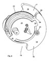
- Fig. 4
- die Massenteile der
Fig. 3 bei mit einer definierten Drehzahl angetriebener Kurbelwelle.
- Fig. 1
- 1 schematically a perspective view of an exemplary embodiment of a mixing device according to the invention with a partially cutaway housing,
- Fig. 2
- schematically a perspective, enlarged bottom view of the eccentric drive of the mixing device according to
Fig. 1 .
- Fig. 3
- only extremely schematically and by way of example an embodiment of the additional mass formed by two mass parts in their basic position when the crankshaft is stationary, and
- Fig. 4
- the mass parts of
Fig. 3 at driven at a defined speed crankshaft.
In der
Die Mischvorrichtung 1 weist eine Halteeinrichtung 3 zur Aufnahme und Halterung eines hier nicht dargestellten Gebindes auf, das in einer Spanneinrichtung 4 der Halteeinrichtung 3 verklemmt wird. Dazu weist die Spanneinrichtung 4 der Halteeinrichtung 3 zwei in etwa vertikal gegenüberliegende Spannteller 5, 6 auf, von denen das obere Spannteller 5 entlang der hier lediglich äußerst schematisch dargestellten Gewindespindeln 7, 8, entsprechend angetrieben über einen hier ebenfalls lediglich äußerst schematisch und beispielhaft dargestellten Spindelantrieb 9 nach unten in Richtung zum einen Aufstandsbereich 10 für das Gebinde ausbildenden unteren Spannteller 6 verlagert wird.The
Wie dies insbesondere auch aus der
Die Drehachse der Kurbelwelle verläuft in Kurbelwellen-Längsrichtung gesehen entlang der durch das freie Wellenende 15 vorgegebenen Richtung, so dass diese Kurbelwelle 14 den Exzenter des Exzenterantriebs 11 ausbildet.The axis of rotation of the crankshaft extends in the crankshaft longitudinal direction along the direction predetermined by the
Wie dies nunmehr insbesondere aus der
Zur Montage werden die beiden Massenteile 16, 17 von gegenüberliegenden Seiten der Kurbelwelle 14 her auf diese aufgesteckt und dann stirnseitig mittels einer Stirnplatte 20 durch zum Beispiel mehrere Schraubverbindungen 21, die hier lediglich äußerst schematisch dargestellt sind, lagefixiert, ohne deren radiale Verschwenkbarkeit relativ zur Kurbelwelle 14 zu beeinträchtigen.For assembly, the two
Wie dies aus der
Die Vorspannkraft der hier beispielhaft als Kraftspeicher fungierenden Spiralfeder 23 ist hier so ausgelegt, dass im Mischbetrieb bei mittels des Antriebsmotors 12 angetriebener Kurbelwelle 14 ab einer definierten und in Abhängigkeit von vorgegebenen Mischparametern vorgegebenen Kurbelwellen-Drehzahl sich die Massenteile 16, 17 von der in der
Der maximale Verlagerungsweg der Massenteile 16, 17 ist durch ein weiteres Anschlagelement 30 an der Stirnplatte 20, das sich hier gegenüberliegend zum Anschlagelement 25 befindet, begrenzt, sobald der Gummipufferanschlag 24 dort zur Anlage kommt. Die stirnplattenseitigen Anschlagelemente 25, 30 sind bevorzugt so ausgebildet, dass die Unwuchtmassen 18, 19 bei dieser maximalen Verlagerungsmöglichkeit einander, bezogen auf den Kurbelwellenumfang, im Wesentlichen überdecken und somit dort die größte Unwucht ausgebildet ist.The maximum displacement of the
Bei einem derartigen Unwuchtbetrieb der Mischvorrichtung 1 wird auf die Halteeinrichtung 3 eine gezielte Oszillations- bzw. Vibrationsbewegung übertragen, wozu die Halteeinrichtung 3, wie dies nunmehr wiederum aus den
Am Ende des Mischbetriebs, wenn der Antriebsmotor 12 abgeschalten wird, verringert sich entsprechend auch die Drehzahl der Kurbelwelle 14 wieder bis zum Stillstand, so dass dann die Spiralfeder 23 die Massenteile 16, 17 wieder in die in der
Wie dies der
Claims (12)
- Mixing device to mix mixtures received in containers,
having a holding device (3) for the receiving and holding of at least one container, and
having an eccentric cam drive (11) having a crankshaft (14) as an eccentric, by means of which the holding device (3) and thus a container received or held in this is able to be set in a defined oscillation and/or vibration movement as a mixing movement,
characterised in that,
the crankshaft (14) is provided with at least one additional mass that is able to be changed depending on the rotational speed and/or is able to be displaced relative to the crankshaft (14), said additional mass, originating from an additional mass base position (29) during standstill of the crankshaft (14), providing an imbalance with increasing rotational speed of the crankshaft which increases to a defined degree and causes the mixing movement of the holding device (3),
in that the additional mass is formed in two parts and has two mass parts (16, 17) braced against each other elastically by means of an energy store, such that the energy store holds the mass parts (16, 17) in the additional mass base position during standstill of the crankshaft (14) and all mass parts (16, 17) are displaced from a defined rotational speed of the crankshaft (14) against the bracing power of the energy storage, and
in that the two mass parts (16, 17) are braced against each other by means of a spiral spring (23) as an energy store, which is led around the crankshaft (14) at least in regions, wherein the spiral spring (23) engages one of the two mass parts (16, 17) with one of its spiral spring ends (26, 27) respectively and pushes and/or braces this into the respective additional mass base position (29) during standstill of the crankshaft (14). - Mixing device according to claim 1, characterised in that the mass parts (16, 17) are designed and/or arranged in such a way that these provide a decreasing imbalance in the case of the rotational speed of the crankshaft (14) decreasing again, until the imbalance of the additional mass base position (29) is achieved during standstill of the crankshaft (14), and/or in that the at least one additional mass (16, 17) provides a defined low or substantially no imbalance during standstill of the crankshaft (14).
- Mixing device according to claim 1 or 2, characterised in that the displacement path of the mass parts (16, 17) is limited in at least one direction by a stop element (24, 25, 30), in particular a rubber buffer, in such a way that the mass parts (16, 17) are pressed against the stop element (25) in the additional mass base position (29) during a substantial standstill of the crankshaft (14) and/or in that, from a defined rotational speed of the crankshaft (14), the mass parts (16, 17) come into contact with the stop element (30).
- Mixing device according to claim 3, characterised in that the stop element (24, 25, 30) is formed in many parts and has, on the crankshaft (14), two first crankshaft-side stop elements (25, 30) that are at a distance from each other, preferably at an angle of 180° from each other, and which interact with a second additional mass-side counter element (24) and are adjacent to the displacement path.
- Mixing device according to one of claims 1 to 4, characterised in that the mass parts (16, 17) are held and/or mounted so that they are able to swivel radially on the crankshaft (14), in particular positively encompass the crankshaft (14) at least in sections and/or are guided into grooves there.
- Mixing device according to one of the preceding claims, characterised in that the spiral spring (23) braces the two mass parts (16, 17) against each other in the additional mass base position (29) during a substantial standstill of the crankshaft (14) in such a way that the mass parts (16, 17) are neutralised to a defined extent with regard to the crankshaft imbalance, preferably substantially completely, in particular in such a way that the imbalance masses (18, 19) of the mass parts (16, 17) generating the imbalance have a defined distance from one another and/or with respect to the crankshaft rotational axis, and
in that the mass parts (16, 17) braced against each other are able to be displaced away from each other with increasing rotational speed of the crankshaft (14) against the force of the spiral spring (23), such that the imbalance of the crankshaft (14) is increased depending on the rotational speed of the crankshaft (14) and/or the displacement path, in particular in such a way that the imbalance masses (18, 19) of the mass parts (16, 17) generating the imbalance are overlapped to an increasing extent. - Mixing device according to one of claims 1 to 6, characterised in that the eccentric cam drive (11) is a component of the holding device (3), which holding device (3) is mounted and/or supported moveably for the generation of the defined mixing movement.
- Mixing device according to clam 7, characterised in that the holding device (3) is mounted and/or supported moveably on a housing (2) of the mixing device (1) by means of at least one bearing device (31), such that the holding device (3) carries out a defined mixing movement in the mixing operation relative to the housing (2).
- Mixing device according to claim 8, characterised in that the bearing device is formed by several supports (31) that are at a distance from one another, engage with the holding device and cause an elastic suspension, in particular by a telescopic support and/or spring damper as a support, causing an elastic suspension.
- Mixing device according to claim 9, characterised in that the supports (31) are mounted with their free support ends in a respective housing-side damping element, preferably an elastomer bearing (34).
- Mixing device according to one of claims 1 to 10, characterised in that the holding device (3) has a clamping device (4) having clamping plates (5, 6) lying approximately vertically opposite each other in the assembled state, at least one of which is able to be displaced in the vertical direction for the clamping reception of a container between the clamping plates (5, 6), wherein it is preferably provided that the eccentric cam drive (11) is held and/or mounted on one of the two clamping plates (5, 6), in particular on a lower clamping plate (6) of the holding device (3) relative to the assembled position.
- Mixing device according to one of claims 1 to 11, characterised in that the eccentric cam drive (11) has an electrical drive motor (12) which drives the crankshaft (14) directly or indirectly by means of a drive belt (13).
Priority Applications (1)
| Application Number | Priority Date | Filing Date | Title |
|---|---|---|---|
| EP10004033.6A EP2377604B1 (en) | 2010-04-16 | 2010-04-16 | Mixing device for mixing mixed goods held in containers |
Applications Claiming Priority (1)
| Application Number | Priority Date | Filing Date | Title |
|---|---|---|---|
| EP10004033.6A EP2377604B1 (en) | 2010-04-16 | 2010-04-16 | Mixing device for mixing mixed goods held in containers |
Publications (2)
| Publication Number | Publication Date |
|---|---|
| EP2377604A1 EP2377604A1 (en) | 2011-10-19 |
| EP2377604B1 true EP2377604B1 (en) | 2014-10-29 |
Family
ID=42697251
Family Applications (1)
| Application Number | Title | Priority Date | Filing Date |
|---|---|---|---|
| EP10004033.6A Active EP2377604B1 (en) | 2010-04-16 | 2010-04-16 | Mixing device for mixing mixed goods held in containers |
Country Status (1)
| Country | Link |
|---|---|
| EP (1) | EP2377604B1 (en) |
Families Citing this family (1)
| Publication number | Priority date | Publication date | Assignee | Title |
|---|---|---|---|---|
| CN105478044B (en) * | 2016-01-12 | 2018-06-26 | 冯丹 | Lift swing oscillator |
Citations (1)
| Publication number | Priority date | Publication date | Assignee | Title |
|---|---|---|---|---|
| US2372791A (en) * | 1944-01-10 | 1945-04-03 | Smith Engineering Works | Screen |
Family Cites Families (7)
| Publication number | Priority date | Publication date | Assignee | Title |
|---|---|---|---|---|
| FR874909A (en) * | 1939-03-30 | 1942-08-31 | Improvements to vibrating devices | |
| CH488528A (en) * | 1968-03-28 | 1970-04-15 | Jacot Simon | Device for deburring, smoothing, polishing and mixing |
| US3919575A (en) * | 1973-10-03 | 1975-11-11 | Bosch Gmbh Robert | Vibrator generator |
| US4619532A (en) * | 1984-11-29 | 1986-10-28 | Everett Douglas Hougen | Shaker for paint containers |
| US4828394A (en) * | 1987-07-17 | 1989-05-09 | Andrews Robin D R | Relating to vibratory machines |
| DE20307593U1 (en) | 2003-05-15 | 2003-07-24 | Collomix Ruehr Mischgeraete | Mixing unit for high viscosity material, comprises housing containing frame, eccentric drive with drive shaft, and tensioning unit |
| ITTO20050726A1 (en) * | 2005-10-12 | 2007-04-13 | Stradale Ltd | DEVICE TO MIX OR AMALGATE LIQUID, GRANULAR OR POWDER PRODUCTS |
-
2010
- 2010-04-16 EP EP10004033.6A patent/EP2377604B1/en active Active
Patent Citations (1)
| Publication number | Priority date | Publication date | Assignee | Title |
|---|---|---|---|---|
| US2372791A (en) * | 1944-01-10 | 1945-04-03 | Smith Engineering Works | Screen |
Also Published As
| Publication number | Publication date |
|---|---|
| EP2377604A1 (en) | 2011-10-19 |
Similar Documents
| Publication | Publication Date | Title |
|---|---|---|
| EP2265419B1 (en) | Hand-held power tool for impacting driven tools | |
| EP1725373B1 (en) | Wobble drive | |
| DE102012009987B4 (en) | laboratory ball mill | |
| EP2927660B1 (en) | Device for testing rotary test samples under load | |
| WO2002053321A1 (en) | Manual machine tool | |
| EP1899245B1 (en) | Linear vibration conveyor | |
| DE102012009984A1 (en) | Laboratory ball mill, particular planetary- or centrifugal force-mono ball mill for crushing and mixing of samples, has carrier device which is rotatably mounted around central axis and grinding station with receiving device | |
| EP2564943A2 (en) | Oscillation exciter for creating an aligned excited oscillation | |
| EP3862487B1 (en) | Vibration plate with electric drive | |
| DE3033476C2 (en) | Vibration device for material compaction | |
| DE102012009982A1 (en) | Laboratory ball mill e.g. planetary mono ball mill for crushing material, has receiving device rotatably mounted to carrier device, which is provided with cage and clamping element for axial clamping of grinding vessel in cage | |
| EP2072183A1 (en) | Surface grinding machine | |
| EP2428788B1 (en) | Device for providing a rotating bearing for a rotor to be balanced | |
| EP2732100B1 (en) | Unbalance exciter for a ground compaction device | |
| DE102007037043A1 (en) | Auxiliary handle device | |
| EP2377604B1 (en) | Mixing device for mixing mixed goods held in containers | |
| EP2578519B1 (en) | Linear vibration conveyer | |
| AT520666A1 (en) | Entkernmaschine for coring of cast workpieces and methods for producing cast workpieces | |
| EP2377602A1 (en) | Clamping device for a mixed goods container in a mixing device | |
| WO2013186372A1 (en) | Ball mill having spatial unbalance compensation | |
| EP1618999B1 (en) | Hand held percussive tool or drill | |
| DE10037680A1 (en) | Flywheel with speed-adaptive vibration damper | |
| DE202010017633U1 (en) | Clamping device for a mixed material container in a mixing device | |
| DE102004035128A1 (en) | Test control unit for stabilizers, has drive unit setting vibrating bodies into torsion vibrations, and supports and coupling units arranged so that stabilizers are mounted symmetrical to rotation axis of frequency response system | |
| DE102015009698B4 (en) | Richterreger and vibrating machine with Richterreger |
Legal Events
| Date | Code | Title | Description |
|---|---|---|---|
| AK | Designated contracting states |
Kind code of ref document: A1 Designated state(s): AT BE BG CH CY CZ DE DK EE ES FI FR GB GR HR HU IE IS IT LI LT LU LV MC MK MT NL NO PL PT RO SE SI SK SM TR |
|
| AX | Request for extension of the european patent |
Extension state: AL BA ME RS |
|
| PUAI | Public reference made under article 153(3) epc to a published international application that has entered the european phase |
Free format text: ORIGINAL CODE: 0009012 |
|
| 17P | Request for examination filed |
Effective date: 20120418 |
|
| 17Q | First examination report despatched |
Effective date: 20120706 |
|
| GRAP | Despatch of communication of intention to grant a patent |
Free format text: ORIGINAL CODE: EPIDOSNIGR1 |
|
| INTG | Intention to grant announced |
Effective date: 20140526 |
|
| GRAS | Grant fee paid |
Free format text: ORIGINAL CODE: EPIDOSNIGR3 |
|
| GRAA | (expected) grant |
Free format text: ORIGINAL CODE: 0009210 |
|
| AK | Designated contracting states |
Kind code of ref document: B1 Designated state(s): AT BE BG CH CY CZ DE DK EE ES FI FR GB GR HR HU IE IS IT LI LT LU LV MC MK MT NL NO PL PT RO SE SI SK SM TR |
|
| REG | Reference to a national code |
Ref country code: GB Ref legal event code: FG4D Free format text: NOT ENGLISH |
|
| REG | Reference to a national code |
Ref country code: CH Ref legal event code: EP |
|
| REG | Reference to a national code |
Ref country code: AT Ref legal event code: REF Ref document number: 693274 Country of ref document: AT Kind code of ref document: T Effective date: 20141115 |
|
| REG | Reference to a national code |
Ref country code: IE Ref legal event code: FG4D Free format text: LANGUAGE OF EP DOCUMENT: GERMAN |
|
| REG | Reference to a national code |
Ref country code: DE Ref legal event code: R096 Ref document number: 502010008124 Country of ref document: DE Effective date: 20141211 |
|
| REG | Reference to a national code |
Ref country code: NL Ref legal event code: T3 |
|
| REG | Reference to a national code |
Ref country code: LT Ref legal event code: MG4D |
|
| PG25 | Lapsed in a contracting state [announced via postgrant information from national office to epo] |
Ref country code: FI Free format text: LAPSE BECAUSE OF FAILURE TO SUBMIT A TRANSLATION OF THE DESCRIPTION OR TO PAY THE FEE WITHIN THE PRESCRIBED TIME-LIMIT Effective date: 20141029 Ref country code: IS Free format text: LAPSE BECAUSE OF FAILURE TO SUBMIT A TRANSLATION OF THE DESCRIPTION OR TO PAY THE FEE WITHIN THE PRESCRIBED TIME-LIMIT Effective date: 20150228 Ref country code: LT Free format text: LAPSE BECAUSE OF FAILURE TO SUBMIT A TRANSLATION OF THE DESCRIPTION OR TO PAY THE FEE WITHIN THE PRESCRIBED TIME-LIMIT Effective date: 20141029 Ref country code: ES Free format text: LAPSE BECAUSE OF FAILURE TO SUBMIT A TRANSLATION OF THE DESCRIPTION OR TO PAY THE FEE WITHIN THE PRESCRIBED TIME-LIMIT Effective date: 20141029 Ref country code: PT Free format text: LAPSE BECAUSE OF FAILURE TO SUBMIT A TRANSLATION OF THE DESCRIPTION OR TO PAY THE FEE WITHIN THE PRESCRIBED TIME-LIMIT Effective date: 20150302 Ref country code: NO Free format text: LAPSE BECAUSE OF FAILURE TO SUBMIT A TRANSLATION OF THE DESCRIPTION OR TO PAY THE FEE WITHIN THE PRESCRIBED TIME-LIMIT Effective date: 20150129 |
|
| PG25 | Lapsed in a contracting state [announced via postgrant information from national office to epo] |
Ref country code: CY Free format text: LAPSE BECAUSE OF FAILURE TO SUBMIT A TRANSLATION OF THE DESCRIPTION OR TO PAY THE FEE WITHIN THE PRESCRIBED TIME-LIMIT Effective date: 20141029 Ref country code: GR Free format text: LAPSE BECAUSE OF FAILURE TO SUBMIT A TRANSLATION OF THE DESCRIPTION OR TO PAY THE FEE WITHIN THE PRESCRIBED TIME-LIMIT Effective date: 20150130 Ref country code: HR Free format text: LAPSE BECAUSE OF FAILURE TO SUBMIT A TRANSLATION OF THE DESCRIPTION OR TO PAY THE FEE WITHIN THE PRESCRIBED TIME-LIMIT Effective date: 20141029 Ref country code: LV Free format text: LAPSE BECAUSE OF FAILURE TO SUBMIT A TRANSLATION OF THE DESCRIPTION OR TO PAY THE FEE WITHIN THE PRESCRIBED TIME-LIMIT Effective date: 20141029 Ref country code: SE Free format text: LAPSE BECAUSE OF FAILURE TO SUBMIT A TRANSLATION OF THE DESCRIPTION OR TO PAY THE FEE WITHIN THE PRESCRIBED TIME-LIMIT Effective date: 20141029 Ref country code: PL Free format text: LAPSE BECAUSE OF FAILURE TO SUBMIT A TRANSLATION OF THE DESCRIPTION OR TO PAY THE FEE WITHIN THE PRESCRIBED TIME-LIMIT Effective date: 20141029 |
|
| REG | Reference to a national code |
Ref country code: DE Ref legal event code: R097 Ref document number: 502010008124 Country of ref document: DE |
|
| PG25 | Lapsed in a contracting state [announced via postgrant information from national office to epo] |
Ref country code: DK Free format text: LAPSE BECAUSE OF FAILURE TO SUBMIT A TRANSLATION OF THE DESCRIPTION OR TO PAY THE FEE WITHIN THE PRESCRIBED TIME-LIMIT Effective date: 20141029 Ref country code: SK Free format text: LAPSE BECAUSE OF FAILURE TO SUBMIT A TRANSLATION OF THE DESCRIPTION OR TO PAY THE FEE WITHIN THE PRESCRIBED TIME-LIMIT Effective date: 20141029 Ref country code: RO Free format text: LAPSE BECAUSE OF FAILURE TO SUBMIT A TRANSLATION OF THE DESCRIPTION OR TO PAY THE FEE WITHIN THE PRESCRIBED TIME-LIMIT Effective date: 20141029 Ref country code: EE Free format text: LAPSE BECAUSE OF FAILURE TO SUBMIT A TRANSLATION OF THE DESCRIPTION OR TO PAY THE FEE WITHIN THE PRESCRIBED TIME-LIMIT Effective date: 20141029 Ref country code: CZ Free format text: LAPSE BECAUSE OF FAILURE TO SUBMIT A TRANSLATION OF THE DESCRIPTION OR TO PAY THE FEE WITHIN THE PRESCRIBED TIME-LIMIT Effective date: 20141029 |
|
| PG25 | Lapsed in a contracting state [announced via postgrant information from national office to epo] |
Ref country code: IT Free format text: LAPSE BECAUSE OF FAILURE TO SUBMIT A TRANSLATION OF THE DESCRIPTION OR TO PAY THE FEE WITHIN THE PRESCRIBED TIME-LIMIT Effective date: 20141029 |
|
| PLBE | No opposition filed within time limit |
Free format text: ORIGINAL CODE: 0009261 |
|
| STAA | Information on the status of an ep patent application or granted ep patent |
Free format text: STATUS: NO OPPOSITION FILED WITHIN TIME LIMIT |
|
| 26N | No opposition filed |
Effective date: 20150730 |
|
| PG25 | Lapsed in a contracting state [announced via postgrant information from national office to epo] |
Ref country code: MC Free format text: LAPSE BECAUSE OF FAILURE TO SUBMIT A TRANSLATION OF THE DESCRIPTION OR TO PAY THE FEE WITHIN THE PRESCRIBED TIME-LIMIT Effective date: 20141029 Ref country code: LU Free format text: LAPSE BECAUSE OF FAILURE TO SUBMIT A TRANSLATION OF THE DESCRIPTION OR TO PAY THE FEE WITHIN THE PRESCRIBED TIME-LIMIT Effective date: 20150416 |
|
| REG | Reference to a national code |
Ref country code: CH Ref legal event code: PL |
|
| REG | Reference to a national code |
Ref country code: IE Ref legal event code: MM4A |
|
| PG25 | Lapsed in a contracting state [announced via postgrant information from national office to epo] |
Ref country code: CH Free format text: LAPSE BECAUSE OF NON-PAYMENT OF DUE FEES Effective date: 20150430 Ref country code: LI Free format text: LAPSE BECAUSE OF NON-PAYMENT OF DUE FEES Effective date: 20150430 |
|
| REG | Reference to a national code |
Ref country code: FR Ref legal event code: ST Effective date: 20151231 |
|
| PG25 | Lapsed in a contracting state [announced via postgrant information from national office to epo] |
Ref country code: FR Free format text: LAPSE BECAUSE OF NON-PAYMENT OF DUE FEES Effective date: 20150430 Ref country code: SI Free format text: LAPSE BECAUSE OF FAILURE TO SUBMIT A TRANSLATION OF THE DESCRIPTION OR TO PAY THE FEE WITHIN THE PRESCRIBED TIME-LIMIT Effective date: 20141029 |
|
| PG25 | Lapsed in a contracting state [announced via postgrant information from national office to epo] |
Ref country code: IE Free format text: LAPSE BECAUSE OF NON-PAYMENT OF DUE FEES Effective date: 20150416 |
|
| REG | Reference to a national code |
Ref country code: AT Ref legal event code: MM01 Ref document number: 693274 Country of ref document: AT Kind code of ref document: T Effective date: 20150416 |
|
| PG25 | Lapsed in a contracting state [announced via postgrant information from national office to epo] |
Ref country code: AT Free format text: LAPSE BECAUSE OF NON-PAYMENT OF DUE FEES Effective date: 20150416 |
|
| PG25 | Lapsed in a contracting state [announced via postgrant information from national office to epo] |
Ref country code: MT Free format text: LAPSE BECAUSE OF FAILURE TO SUBMIT A TRANSLATION OF THE DESCRIPTION OR TO PAY THE FEE WITHIN THE PRESCRIBED TIME-LIMIT Effective date: 20141029 |
|
| PG25 | Lapsed in a contracting state [announced via postgrant information from national office to epo] |
Ref country code: HU Free format text: LAPSE BECAUSE OF FAILURE TO SUBMIT A TRANSLATION OF THE DESCRIPTION OR TO PAY THE FEE WITHIN THE PRESCRIBED TIME-LIMIT; INVALID AB INITIO Effective date: 20100416 Ref country code: BG Free format text: LAPSE BECAUSE OF FAILURE TO SUBMIT A TRANSLATION OF THE DESCRIPTION OR TO PAY THE FEE WITHIN THE PRESCRIBED TIME-LIMIT Effective date: 20141029 Ref country code: SM Free format text: LAPSE BECAUSE OF FAILURE TO SUBMIT A TRANSLATION OF THE DESCRIPTION OR TO PAY THE FEE WITHIN THE PRESCRIBED TIME-LIMIT Effective date: 20141029 |
|
| PG25 | Lapsed in a contracting state [announced via postgrant information from national office to epo] |
Ref country code: BE Free format text: LAPSE BECAUSE OF NON-PAYMENT OF DUE FEES Effective date: 20150430 |
|
| PG25 | Lapsed in a contracting state [announced via postgrant information from national office to epo] |
Ref country code: TR Free format text: LAPSE BECAUSE OF FAILURE TO SUBMIT A TRANSLATION OF THE DESCRIPTION OR TO PAY THE FEE WITHIN THE PRESCRIBED TIME-LIMIT Effective date: 20141029 |
|
| PG25 | Lapsed in a contracting state [announced via postgrant information from national office to epo] |
Ref country code: MK Free format text: LAPSE BECAUSE OF FAILURE TO SUBMIT A TRANSLATION OF THE DESCRIPTION OR TO PAY THE FEE WITHIN THE PRESCRIBED TIME-LIMIT Effective date: 20141029 |
|
| REG | Reference to a national code |
Ref country code: DE Ref legal event code: R079 Ref document number: 502010008124 Country of ref document: DE Free format text: PREVIOUS MAIN CLASS: B01F0015000000 Ipc: B01F0035000000 |
|
| PGFP | Annual fee paid to national office [announced via postgrant information from national office to epo] |
Ref country code: NL Payment date: 20230426 Year of fee payment: 14 |
|
| P01 | Opt-out of the competence of the unified patent court (upc) registered |
Effective date: 20230526 |
|
| PGFP | Annual fee paid to national office [announced via postgrant information from national office to epo] |
Ref country code: DE Payment date: 20230620 Year of fee payment: 14 |
|
| PGFP | Annual fee paid to national office [announced via postgrant information from national office to epo] |
Ref country code: GB Payment date: 20230420 Year of fee payment: 14 |