EP2376880B1 - Method and system for detecting small amounts of substances - Google Patents
Method and system for detecting small amounts of substances Download PDFInfo
- Publication number
- EP2376880B1 EP2376880B1 EP09833742.1A EP09833742A EP2376880B1 EP 2376880 B1 EP2376880 B1 EP 2376880B1 EP 09833742 A EP09833742 A EP 09833742A EP 2376880 B1 EP2376880 B1 EP 2376880B1
- Authority
- EP
- European Patent Office
- Prior art keywords
- light
- area
- detection
- wavelength
- individual
- Prior art date
- Legal status (The legal status is an assumption and is not a legal conclusion. Google has not performed a legal analysis and makes no representation as to the accuracy of the status listed.)
- Active
Links
- 239000000126 substance Substances 0.000 title claims description 34
- 238000000034 method Methods 0.000 title claims description 12
- 238000001514 detection method Methods 0.000 claims description 51
- 230000003287 optical effect Effects 0.000 claims description 33
- 239000002245 particle Substances 0.000 claims description 21
- 238000001228 spectrum Methods 0.000 claims description 11
- 238000001237 Raman spectrum Methods 0.000 claims description 9
- 239000002360 explosive Substances 0.000 claims description 8
- 239000000383 hazardous chemical Substances 0.000 claims description 6
- 238000004458 analytical method Methods 0.000 claims description 3
- 238000001914 filtration Methods 0.000 claims description 2
- 238000012545 processing Methods 0.000 description 8
- 238000001069 Raman spectroscopy Methods 0.000 description 7
- 230000003595 spectral effect Effects 0.000 description 6
- 238000005259 measurement Methods 0.000 description 4
- 239000002575 chemical warfare agent Substances 0.000 description 3
- 231100001261 hazardous Toxicity 0.000 description 3
- 230000006641 stabilisation Effects 0.000 description 3
- 238000011105 stabilization Methods 0.000 description 3
- 238000001499 laser induced fluorescence spectroscopy Methods 0.000 description 2
- 238000012986 modification Methods 0.000 description 2
- 230000004048 modification Effects 0.000 description 2
- 239000002243 precursor Substances 0.000 description 2
- 241000295146 Gallionellaceae Species 0.000 description 1
- 238000007630 basic procedure Methods 0.000 description 1
- 230000005540 biological transmission Effects 0.000 description 1
- 239000000599 controlled substance Substances 0.000 description 1
- 230000001419 dependent effect Effects 0.000 description 1
- 238000013461 design Methods 0.000 description 1
- 239000003814 drug Substances 0.000 description 1
- 229940079593 drug Drugs 0.000 description 1
- 230000000694 effects Effects 0.000 description 1
- 239000013056 hazardous product Substances 0.000 description 1
- 239000003317 industrial substance Substances 0.000 description 1
- 239000004973 liquid crystal related substance Substances 0.000 description 1
- 238000012544 monitoring process Methods 0.000 description 1
- 238000004091 panning Methods 0.000 description 1
- 238000011202 physical detection method Methods 0.000 description 1
- 238000001945 resonance Rayleigh scattering spectroscopy Methods 0.000 description 1
- 230000035939 shock Effects 0.000 description 1
- 230000000087 stabilizing effect Effects 0.000 description 1
- 231100000331 toxic Toxicity 0.000 description 1
- 230000002588 toxic effect Effects 0.000 description 1
Images
Classifications
-
- G—PHYSICS
- G01—MEASURING; TESTING
- G01J—MEASUREMENT OF INTENSITY, VELOCITY, SPECTRAL CONTENT, POLARISATION, PHASE OR PULSE CHARACTERISTICS OF INFRARED, VISIBLE OR ULTRAVIOLET LIGHT; COLORIMETRY; RADIATION PYROMETRY
- G01J3/00—Spectrometry; Spectrophotometry; Monochromators; Measuring colours
- G01J3/02—Details
- G01J3/06—Scanning arrangements arrangements for order-selection
-
- G—PHYSICS
- G01—MEASURING; TESTING
- G01J—MEASUREMENT OF INTENSITY, VELOCITY, SPECTRAL CONTENT, POLARISATION, PHASE OR PULSE CHARACTERISTICS OF INFRARED, VISIBLE OR ULTRAVIOLET LIGHT; COLORIMETRY; RADIATION PYROMETRY
- G01J3/00—Spectrometry; Spectrophotometry; Monochromators; Measuring colours
- G01J3/28—Investigating the spectrum
- G01J3/44—Raman spectrometry; Scattering spectrometry ; Fluorescence spectrometry
-
- G—PHYSICS
- G01—MEASURING; TESTING
- G01J—MEASUREMENT OF INTENSITY, VELOCITY, SPECTRAL CONTENT, POLARISATION, PHASE OR PULSE CHARACTERISTICS OF INFRARED, VISIBLE OR ULTRAVIOLET LIGHT; COLORIMETRY; RADIATION PYROMETRY
- G01J3/00—Spectrometry; Spectrophotometry; Monochromators; Measuring colours
- G01J3/28—Investigating the spectrum
- G01J3/2803—Investigating the spectrum using photoelectric array detector
-
- G—PHYSICS
- G01—MEASURING; TESTING
- G01J—MEASUREMENT OF INTENSITY, VELOCITY, SPECTRAL CONTENT, POLARISATION, PHASE OR PULSE CHARACTERISTICS OF INFRARED, VISIBLE OR ULTRAVIOLET LIGHT; COLORIMETRY; RADIATION PYROMETRY
- G01J3/00—Spectrometry; Spectrophotometry; Monochromators; Measuring colours
- G01J3/28—Investigating the spectrum
- G01J3/30—Measuring the intensity of spectral lines directly on the spectrum itself
- G01J3/32—Investigating bands of a spectrum in sequence by a single detector
-
- G—PHYSICS
- G01—MEASURING; TESTING
- G01N—INVESTIGATING OR ANALYSING MATERIALS BY DETERMINING THEIR CHEMICAL OR PHYSICAL PROPERTIES
- G01N21/00—Investigating or analysing materials by the use of optical means, i.e. using sub-millimetre waves, infrared, visible or ultraviolet light
- G01N21/62—Systems in which the material investigated is excited whereby it emits light or causes a change in wavelength of the incident light
- G01N21/63—Systems in which the material investigated is excited whereby it emits light or causes a change in wavelength of the incident light optically excited
- G01N21/65—Raman scattering
-
- G—PHYSICS
- G01—MEASURING; TESTING
- G01N—INVESTIGATING OR ANALYSING MATERIALS BY DETERMINING THEIR CHEMICAL OR PHYSICAL PROPERTIES
- G01N21/00—Investigating or analysing materials by the use of optical means, i.e. using sub-millimetre waves, infrared, visible or ultraviolet light
- G01N21/84—Systems specially adapted for particular applications
- G01N21/88—Investigating the presence of flaws or contamination
-
- G—PHYSICS
- G01—MEASURING; TESTING
- G01N—INVESTIGATING OR ANALYSING MATERIALS BY DETERMINING THEIR CHEMICAL OR PHYSICAL PROPERTIES
- G01N33/00—Investigating or analysing materials by specific methods not covered by groups G01N1/00 - G01N31/00
- G01N33/0004—Gaseous mixtures, e.g. polluted air
- G01N33/0009—General constructional details of gas analysers, e.g. portable test equipment
- G01N33/0027—General constructional details of gas analysers, e.g. portable test equipment concerning the detector
- G01N33/0036—General constructional details of gas analysers, e.g. portable test equipment concerning the detector specially adapted to detect a particular component
- G01N33/0057—Warfare agents or explosives
-
- G—PHYSICS
- G01—MEASURING; TESTING
- G01N—INVESTIGATING OR ANALYSING MATERIALS BY DETERMINING THEIR CHEMICAL OR PHYSICAL PROPERTIES
- G01N33/00—Investigating or analysing materials by specific methods not covered by groups G01N1/00 - G01N31/00
- G01N33/22—Fuels; Explosives
- G01N33/227—Explosives, e.g. combustive properties thereof
-
- G—PHYSICS
- G01—MEASURING; TESTING
- G01N—INVESTIGATING OR ANALYSING MATERIALS BY DETERMINING THEIR CHEMICAL OR PHYSICAL PROPERTIES
- G01N21/00—Investigating or analysing materials by the use of optical means, i.e. using sub-millimetre waves, infrared, visible or ultraviolet light
- G01N21/17—Systems in which incident light is modified in accordance with the properties of the material investigated
- G01N2021/1793—Remote sensing
Definitions
- the present invention relates to detection of substances or molecules, in particular detection of very small amounts of substances or of particles of substances at stand-off distances.
- a substance e.g. an explosive substance or a controlled drug, that is hit by a laser beam will reflect or scatter most of the received light.
- the reflected and scattered light will mainly have the same wavelength as the received light, however some of the scattered light will be wavelength-shifted, this being “Raman scattered” light.
- the distribution of this scattered light comprising light of a plurality of wavelengths is called a "Raman spectrum”.
- the Raman spectrum for each substance or more precisely for each type of molecule thus, in the way similar to other spectra, comprises one or more wavelength bands/lines and is molecule-specific. Every band or line in the Raman spectrum corresponds to a vibrational mode in the molecule. Due to the unique Raman spectrum for each molecule a substance can be identified by comparing a measured Raman spectrum to reference spectra.
- a laser beam is directed at the substance and the reflected and scattered light is collected using a telescope.
- the Raman spectrum is measured using an optical filter system and an optical sensor.
- a signal processing algorithm is used to compare the measured spectrum to various spectra stored in a database.
- Remote detection can be assumed to be made at distances, these distances called stand-off distances, larger than those ordinarily in a laboratory where the substance to be examined is placed in a direct vicinity of a spectrometer, the distance generally being taken as larger than 50 cm or commonly larger than 5 m and often in the range of 10 -100 m.
- a difficult task in substance detection is to identify small amounts, also called trace amounts, of a relevant substance or a substance searched for that is located amid many other substances.
- a signal from the relevant substance is obtained together with signals from the other substances, where the latter signals can be called noise.
- SNR signal-to-noise ratio
- One such task is to identify substances present in fingerprints, where a number of other substances may also be present.
- Substances in fingerprints usually present themselves in the form of particles. Therefore, in order to maximize the SNR it is desirable to perform the detection using the area of the fingerprint where the ratio of relevant particles to irrelevant particles is as high as possible.
- the area having the largest SNR is obviously the area of one relevant particle, excluding all surrounding area. This is true not only for fingerprints, but for every application where it is desirable to detect trace amounts of substances in a cluttered environment.
- the detector used must have a near part-ide-size resolution at stand-off distances and second, the detector has to be capable of locating near particle-sized objects at stand-off distances.
- an area of detection or of interest can be divided into a plurality of smaller areas, herein called subareas, where the size of each subarea is comparable to the size of one or of a plurality of, e.g. a few such as 2 - 5 or better 2 - 3, particles. Since such a subarea will contain only one or only a few particles the SNR thereof will be high if any relevant particle is present. In extreme cases, such as for detecting special organic molecules, the subareas may even have a size comparable to the of a single or of a few molecules.
- any subarea of the larger area having one or a few relevant particles can be found.
- a laser beam is directed at a target, focusing a telescope at a place on the target illuminated by the laser beam and depicting the telescope image on a camera having several picture elements. Each picture element will then correspond to an individual element subarea on the target.
- An optical filter inserted between the telescope and the camera provides spectral information regarding the substances on the target. By repetitiously changing the band-pass wavelength of the optical filter, and collecting the response of the camera for each filter setting, the individual spectral response for each element subarea can be determined.
- Fig. 1 is a schematic of apparatus for standoff Raman spectroscopy, i.e. Raman spectroscopy for an object located at a relatively large distance of the device for collecting Raman scattered light.
- a monochromatic light beam is issued by a laser 1 and is directed at an area 2 or region of a target 3. When the light of the light beam hits the area, most of the light is scattered. Also, most of the scattered light has the same wavelength as the light hitting the area. However, a small fraction of the scattered light has shifted wavelengths.
- the scattered light is collected by an optical telescope 4 that is set to sharply depict the area 2 illuminated by the laser beam.
- the optical telescope obviously collects all light, including both reflected and scattered light, issued from the depicted area in the direction of the telescope, the reflected light constituting noise.
- the telescope image is depicted on the light sensitive surface 5 of a camera 6, the light sensitive surface comprising a plurality of picture elements 7, also called pixels, see Fig. 2 .
- the light sensitive surface may be called a pixel array.
- Each of the picture elements then corresponds to an individual element subarea 2' included in the illuminated area 2 of the target 3.
- Some device for obtaining spectral information about the substances in the illuminated area 3 of the target such as an optical filter 8 can be inserted between the telescope 4 and the camera 6.
- the optical filter can be the band-pass type, i.e. it can be designed to allow transmission of light only within a wavelength window.
- the size of the image of a particle may e.g. roughly be of the same magnitude as a pixel 7 and then the particle may also have a size approximately corresponding to that of the element subarea 2' that corresponds to the pixel.
- the pixel size and the stand-off distance determine the design parameters of the optical system.
- the magnification of the optical system may be determined so that the element subarea corresponding to a pixel has a size dependent on characteristics of the relevant substances and their particle size distribution, and considering the background noise, as discussed above, i.e. the contribution from irrelevant substances in the signal resulting from detection in the light sensitive surface 5 of the camera 6, the physical detection method used and the desired SNR.
- the particle size is typically in the range of 1 - 100 ⁇ m and stand-off distances can e.g. be up to 1000 m.
- the shape of the pixels 7 and the shape of the pixel array 5 may be arbitrary.
- the rectangular or square picture element and the rectangular pixel array seen in Fig, 2 represent the typical shapes found in commercial cameras, however, a single row or a single column of pixels or a non-regular or non-contiguous configuration of pixels may also be used.
- the detection method used can be ordinary Raman spectroscopy.
- Other detection methods that can be used include variations of Raman Spectroscopy, e.g. near-resonant Raman spectroscopy and resonance-enhanced Raman spectroscopy (RRS or RERS), and similar methods such as Laser-Induced Fluorescence (LIF).
- Raman Spectroscopy e.g. near-resonant Raman spectroscopy and resonance-enhanced Raman spectroscopy (RRS or RERS), and similar methods such as Laser-Induced Fluorescence (LIF).
- LIF Laser-Induced Fluorescence
- the optical filter 8 may e.g. be an LCTF (Liquid Crystal Tunable Filter) or an AOTF (Acousto-Optical Tunable Filter).
- the laser 1 can be an Nd-YAG pulsed laser but other lasers such as excimer lasers, e.g. KrF lasers, may also be used. Some applications may also use continuous-wave (CW) lasers. Some applications may require tunable lasers for e.g. fluorescence rejection and resonance enhancement.
- the relevant substances suitable to detect can include, but are not limited to explosives, explosives markers and explosives precursors.
- Other substances of interest may be TICs (Toxic Industrial Chemicals), CWAs (Chemical Warfare Agents), drugs, drug-pre-cursors and hazardous substances in general.
- non-hazardous substances indicative of a hazardous activity and/or of hazardous contents may be of interest.
- the apparatus can include a control unit 11 comprising units or modules for executing various tasks.
- a laser control module 12 can be connected to the laser 1 for controlling when light pulses are emitted and the length of the pulses.
- a camera module 13 can be connected to the camera 6 for controlling when the pixels 7 of the light sensitive surface 5 are open for detecting light and for controlling the length of their detection time periods.
- the signals from the camera can be input to an image processing unit 14 which e.g. can select the pixels, the signals from which are suited for analysis.
- a filter module 15 is connected to the optical filter 8 for controlling the filtering characteristics thereof.
- the basic procedure when searching for a specific substance or molecule in the target 3 can be as follows.
- the relevant pixel 7 may be a single pixel which corresponds to the total area 2 illuminated by the laser beam, i.e. the areas 2 and 2' may be identical. If the area 2 illuminated by the laser beam is depicted on a group of pixels 7, the signals stored for each pixel in the group can be analyzed individually or the signals from all pixels in the group can be summed for each setting of the optical filter 8 and the resulting sums can then be analyzed.
- the method can be adapted to various special cases by e.g. selecting the location of the illuminated area 2 and the shape thereof and by analyzing the signals obtained for e.g. groups of pixels 7 together with each other. Such a group of pixels then correspond to a subarea on the target 3 included in the illuminated area 2 but larger than each of the element subareas 2'. Special embodiments will now be described.
- some stabilization device or method can be used, e.g. mechanical or optical stabilization.
- image processing such as that performed in the image processing module 14 can be used to stabilize the detection.
- the laser 1 can be set to emit light pulses of e.g. the length 10 ns.
- the camera control module 13 controls the camera 6 to be open for detection only within suitably set time windows so that the pixels 7 only detect received light, i.e. taking pictures, during these time windows.
- the time windows are e.g. set to have a selected delay in relay to each issued light pulse and to have a suitably selected length to give an optimum detection of only light scattered from the illuminated subarea.
- an image stabilizing procedure can be used, e.g. executed in an image stabilization module 18, in which the taken pictures are compared to each other and if necessary displaced, so that in all the resulting pictures the signals for each pixel come from the same element subarea 2' of the object 3.
- the resulting pictures are analyzed by e.g. summing the signals for each pixel 7 of the selected subarea and each setting of the optical filter 8. These sums then constitute the measured spectrum of scattered light for the selected subarea.
- Image processing may be used to identify areas on the target which are of particular interest for detection.
- First an overview picture of the target 3 for some suitable wavelength band can be captured and thereupon the captured picture is analyzed for images of objects matching already captured pictures of objects in a built-in or externally available database, not shown. Examples of such objects include door handles, which are likely to contain trace amounts from fingerprints.
- the detector system may then be manually or automatically directed at one or more of such identified areas.
- Image processing may also be used to match patterns of detected particles to patterns in a database, not shown.
- An object of interest may first be analyzed for the existence of particles of substances, the spectra of which are included in the database. Then the location of the particles in a picture of the whole object is matched against known patterns of particle location.
- An area and/or an object can be scanned using:
- the laser beam may be formed or shaped, e.g. by a suitable optical system, not shown, to have a cross-section having the shape of a thin bar or a thin straight line so that it illuminates a corresponding strip-shaped area 2" of the target 3, i.e. of the object of interest, see Fig. 4 .
- the width of the strip-shaped area can correspond to the width of a subarea of interest. In particular it can correspond to or possibly slightly exceed, such as not exceeding by more than 25 % or better 10 %, the width or height of an area that is depicted on a single pixel, i.e. of an element subarea 2'.
- the light sensitive surface 5 of the camera 6 may then include only a single linear array of pixels 7, i.e.
- the pixels may as in conventional cameras have a rectangular or square shape but they could also be e.g. polygonal.
- the illuminated thin line may be oriented horizontally, vertically or in an arbitrary direction.
- An area and/or an object can be scanned using a "bar-laser" as described above.
- the scanning can be made from a stationary geographical location using a detection device having pan and tilt functions as above.
- the scanning can alternatively be performed in the "moving" way described above.
- the detection device may optionally also have a pan function or a tilt function or both these functions.
- a laser beam formed to have a cross-section of a bar or a thin straight line as described above can also be used together with a conventional rectangular light sensitive surface 5 having a plurality of horizontal rows and a plurality of vertical columns of pixels 7 as seen in Fig. 4 . Then the area of the light sensitive surface 5 that corresponds to the illuminated linear area 2" on the target 3 is active for detection.
- a wavelength dispersive device 19 of an edge or linear type e.g. a cylinder-segment lens, a prism or a diffraction grating, see Fig. 3 , can be used.
- the wavelength dispersive device can be placed to deflect the collected reflected and scattered light output from the telescope 4 before it passes onto the array 5 of pixels 7.
- the wavelength dispersive device 19 will for a proper positioning deflect the light so that light of different wavelengths hits different areas of the array 5 of pixels. Then, usually light of the longest wavelengths hits a straight line of pixels at one end or side of the pixel array and light of the shortest wavelengths hits a straight line of pixels at the opposite end or side of the pixel array.
- the information or signals obtained from a row of pixels, or a column then represents/represent the intensity of light, scattered from the corresponding linear area of the target and having wavelengths only within a narrow wavelength band, i.e. the spectral response for a narrow wavelength band from the illuminated area of the target.
- a laser beam which illuminates an area 2 of the object 3 corresponding to one or more pixels 7 can be used.
- the spectrum is obtained in one measurement using spectral-spreading techniques or several measurements of one spectral band at a time.
- the beam is moved to the next subarea, that can be adjacent or non-adjacent, and another measurement is made.
- the image of the total object 3 is obtained by adding the responses from the individual subareas for which measurements have been made.
- the detection system as described herein can be used in ordinary land-based vehicles but also in un-manned vehicles, e.g. in a UAV (Unmanned Aerial Vehicle) or in a naval vehicle.
- un-manned vehicles e.g. in a UAV (Unmanned Aerial Vehicle) or in a naval vehicle.
Landscapes
- Physics & Mathematics (AREA)
- Spectroscopy & Molecular Physics (AREA)
- General Physics & Mathematics (AREA)
- Health & Medical Sciences (AREA)
- Chemical & Material Sciences (AREA)
- Life Sciences & Earth Sciences (AREA)
- Pathology (AREA)
- Analytical Chemistry (AREA)
- Biochemistry (AREA)
- General Health & Medical Sciences (AREA)
- Immunology (AREA)
- Engineering & Computer Science (AREA)
- Nuclear Medicine, Radiotherapy & Molecular Imaging (AREA)
- Combustion & Propulsion (AREA)
- Food Science & Technology (AREA)
- Medicinal Chemistry (AREA)
- Investigating, Analyzing Materials By Fluorescence Or Luminescence (AREA)
- Investigating Or Analysing Materials By Optical Means (AREA)
Description
- The present invention relates to detection of substances or molecules, in particular detection of very small amounts of substances or of particles of substances at stand-off distances.
- A substance, e.g. an explosive substance or a controlled drug, that is hit by a laser beam will reflect or scatter most of the received light. The reflected and scattered light will mainly have the same wavelength as the received light, however some of the scattered light will be wavelength-shifted, this being "Raman scattered" light. The distribution of this scattered light comprising light of a plurality of wavelengths is called a "Raman spectrum".
- The Raman spectrum for each substance or more precisely for each type of molecule thus, in the way similar to other spectra, comprises one or more wavelength bands/lines and is molecule-specific. Every band or line in the Raman spectrum corresponds to a vibrational mode in the molecule. Due to the unique Raman spectrum for each molecule a substance can be identified by comparing a measured Raman spectrum to reference spectra.
- For stand-off detection, i.e. remote detection or detection at some distance, a laser beam is directed at the substance and the reflected and scattered light is collected using a telescope. The Raman spectrum is measured using an optical filter system and an optical sensor. In order to identify the substance or molecule for which the Raman spectrum has been measured a signal processing algorithm is used to compare the measured spectrum to various spectra stored in a database. Remote detection can be assumed to be made at distances, these distances called stand-off distances, larger than those ordinarily in a laboratory where the substance to be examined is placed in a direct vicinity of a spectrometer, the distance generally being taken as larger than 50 cm or commonly larger than 5 m and often in the range of 10 -100 m.
- A difficult task in substance detection is to identify small amounts, also called trace amounts, of a relevant substance or a substance searched for that is located amid many other substances. In the detection, conventionally a signal from the relevant substance is obtained together with signals from the other substances, where the latter signals can be called noise. The lower the proportion of signal to noise, this called the signal-to-noise ratio (SNR), is, the more difficult the detection becomes. This problem is common to a multitude of applications for particle detection.
- One such task is to identify substances present in fingerprints, where a number of other substances may also be present. Substances in fingerprints usually present themselves in the form of particles. Therefore, in order to maximize the SNR it is desirable to perform the detection using the area of the fingerprint where the ratio of relevant particles to irrelevant particles is as high as possible. The area having the largest SNR is obviously the area of one relevant particle, excluding all surrounding area. This is true not only for fingerprints, but for every application where it is desirable to detect trace amounts of substances in a cluttered environment.
- To achieve this, two objectives have to be met. First, the detector used must have a near part-ide-size resolution at stand-off distances and second, the detector has to be capable of locating near particle-sized objects at stand-off distances.
- In the examination of the present patent application
US 2007/0081156A1 was cited. While it shows some of the characteristics of the present invention, it does not show stand-off distances of 10-100 meters, which are used in the present invention. Furthermore, it is directed towards detecting bioagents, not hazardous molecules of a definite kind. The mere mentioning in passing of chemical warfare agents detection or hazardous material monitoring does not give information enough about such a use. - It is an object of the present invention to provide a method according to
claim 1 and a device according toclaim 6 for detecting very small amounts of substances. - Generally, an area of detection or of interest can be divided into a plurality of smaller areas, herein called subareas, where the size of each subarea is comparable to the size of one or of a plurality of, e.g. a few such as 2 - 5 or better 2 - 3, particles. Since such a subarea will contain only one or only a few particles the SNR thereof will be high if any relevant particle is present. In extreme cases, such as for detecting special organic molecules, the subareas may even have a size comparable to the of a single or of a few molecules.
- By grouping a plurality of subareas to form a larger area and simultaneously detecting all individual subareas included in said plurality, any subarea of the larger area having one or a few relevant particles can be found.
- Generally, in detecting a substance, a laser beam is directed at a target, focusing a telescope at a place on the target illuminated by the laser beam and depicting the telescope image on a camera having several picture elements. Each picture element will then correspond to an individual element subarea on the target. An optical filter inserted between the telescope and the camera provides spectral information regarding the substances on the target. By repetitiously changing the band-pass wavelength of the optical filter, and collecting the response of the camera for each filter setting, the individual spectral response for each element subarea can be determined.
- The present invention is defined in the appended claims.
- The invention will be better appreciated from a consideration of the following detailed description of non-limiting embodiments presented hereinbelow with reference to the accompanying drawings, in which:
-
Fig. 1 is a schematic of a detection system for detecting small amounts of substances, -
Fig. 2 is a schematic illustrating how particles are imaged onto individual pixels, -
Fig. 3 is a schematic similar toFig. 1 having also a wavelength separating device, and -
Fig. 4 is a schematic similar toFig. 2 for an illuminated strip imaged onto corresponding pixels. -
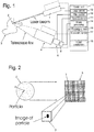
Fig. 1 is a schematic of apparatus for standoff Raman spectroscopy, i.e. Raman spectroscopy for an object located at a relatively large distance of the device for collecting Raman scattered light. A monochromatic light beam is issued by alaser 1 and is directed at anarea 2 or region of atarget 3. When the light of the light beam hits the area, most of the light is scattered. Also, most of the scattered light has the same wavelength as the light hitting the area. However, a small fraction of the scattered light has shifted wavelengths. The scattered light is collected by an optical telescope 4 that is set to sharply depict thearea 2 illuminated by the laser beam. The optical telescope obviously collects all light, including both reflected and scattered light, issued from the depicted area in the direction of the telescope, the reflected light constituting noise. The telescope image is depicted on the lightsensitive surface 5 of acamera 6, the light sensitive surface comprising a plurality ofpicture elements 7, also called pixels, seeFig. 2 . Thus, the light sensitive surface may be called a pixel array. Each of the picture elements then corresponds to an individual element subarea 2' included in theilluminated area 2 of thetarget 3. - Some device for obtaining spectral information about the substances in the
illuminated area 3 of the target such as anoptical filter 8 can be inserted between the telescope 4 and thecamera 6. The optical filter can be the band-pass type, i.e. it can be designed to allow transmission of light only within a wavelength window. By repetitiously changing the setting of the optical filter, such as moving the wavelength window of theoptical filter 8, and collecting the response of thecamera 6 for each chosen setting or wavelength window, the individual spectral response for each of the element subareas 2' included in theilluminated area 2 can be determined. - As can be seen in
Fig. 2 the size of the image of a particle may e.g. roughly be of the same magnitude as apixel 7 and then the particle may also have a size approximately corresponding to that of the element subarea 2' that corresponds to the pixel. The pixel size and the stand-off distance determine the design parameters of the optical system. The magnification of the optical system may be determined so that the element subarea corresponding to a pixel has a size dependent on characteristics of the relevant substances and their particle size distribution, and considering the background noise, as discussed above, i.e. the contribution from irrelevant substances in the signal resulting from detection in the lightsensitive surface 5 of thecamera 6, the physical detection method used and the desired SNR. The particle size is typically in the range of 1 - 100 µm and stand-off distances can e.g. be up to 1000 m. - The shape of the
pixels 7 and the shape of thepixel array 5 may be arbitrary. The rectangular or square picture element and the rectangular pixel array seen inFig, 2 represent the typical shapes found in commercial cameras, however, a single row or a single column of pixels or a non-regular or non-contiguous configuration of pixels may also be used. - The detection method used can be ordinary Raman spectroscopy. Other detection methods that can be used include variations of Raman Spectroscopy, e.g. near-resonant Raman spectroscopy and resonance-enhanced Raman spectroscopy (RRS or RERS), and similar methods such as Laser-Induced Fluorescence (LIF).
- The
optical filter 8 may e.g. be an LCTF (Liquid Crystal Tunable Filter) or an AOTF (Acousto-Optical Tunable Filter). Thelaser 1 can be an Nd-YAG pulsed laser but other lasers such as excimer lasers, e.g. KrF lasers, may also be used. Some applications may also use continuous-wave (CW) lasers. Some applications may require tunable lasers for e.g. fluorescence rejection and resonance enhancement. - The relevant substances suitable to detect can include, but are not limited to explosives, explosives markers and explosives precursors. Other substances of interest may be TICs (Toxic Industrial Chemicals), CWAs (Chemical Warfare Agents), drugs, drug-pre-cursors and hazardous substances in general. Also, non-hazardous substances indicative of a hazardous activity and/or of hazardous contents may be of interest.
- The apparatus can include a
control unit 11 comprising units or modules for executing various tasks. Thus, alaser control module 12 can be connected to thelaser 1 for controlling when light pulses are emitted and the length of the pulses. Acamera module 13 can be connected to thecamera 6 for controlling when thepixels 7 of the lightsensitive surface 5 are open for detecting light and for controlling the length of their detection time periods. The signals from the camera can be input to animage processing unit 14 which e.g. can select the pixels, the signals from which are suited for analysis. Afilter module 15 is connected to theoptical filter 8 for controlling the filtering characteristics thereof. - As appears from the description above, the basic procedure when searching for a specific substance or molecule in the
target 3 can be as follows. - 1. The
laser 1 is set so that its emitted light beam is directed to anarea 2 on thetarget 3. - 2. The telescope 4 is set so that it sharply or distinctly depicts the illuminated
area 2. - 3. The
optical filter 8 is set to allow light of a first wavelength band to pass. - 4. The
camera 6 is activated to take a picture. The signal from eachpixel 7 is fed to thecontrol unit 11 and stored. - 5. The setting of the
optical filter 8 is changed to allow light of another wavelength to pass. - 6. The steps 4. and 5. are repeated until signals from the
camera 6 for light of each wavelength band of interest have been recorded. - 7. The stored signals for a relevant one of the
pixels 7 or for each one of a group of pixels are analyzed by e.g. comparing them to already stored signal patterns. The result of the comparison is stored. - 8. The direction of the laser beam is changed so that it hits another
area 2 of thetarget 3. - 9. The
steps 2. - 7. are repeated for this another illuminatedarea 2. - 10. The stored results are evaluated.
- In the comparing
step 7. therelevant pixel 7 may be a single pixel which corresponds to thetotal area 2 illuminated by the laser beam, i.e. theareas 2 and 2' may be identical. If thearea 2 illuminated by the laser beam is depicted on a group ofpixels 7, the signals stored for each pixel in the group can be analyzed individually or the signals from all pixels in the group can be summed for each setting of theoptical filter 8 and the resulting sums can then be analyzed. - Generally, the method can be adapted to various special cases by e.g. selecting the location of the illuminated
area 2 and the shape thereof and by analyzing the signals obtained for e.g. groups ofpixels 7 together with each other. Such a group of pixels then correspond to a subarea on thetarget 3 included in the illuminatedarea 2 but larger than each of the element subareas 2'. Special embodiments will now be described. - In the case where the telescope 4 is exposed to mechanical shock and vibration, some stabilization device or method can be used, e.g. mechanical or optical stabilization. Also image processing such as that performed in the
image processing module 14 can be used to stabilize the detection. In particular, thelaser 1 can be set to emit light pulses of e.g. the length 10 ns. Thecamera control module 13 controls thecamera 6 to be open for detection only within suitably set time windows so that thepixels 7 only detect received light, i.e. taking pictures, during these time windows. The time windows are e.g. set to have a selected delay in relay to each issued light pulse and to have a suitably selected length to give an optimum detection of only light scattered from the illuminated subarea. If the telescope 4 is moving during the detection, the detected signals from eachpixel 5 will not come from the same small element subarea 2' of theobject 3. Before evaluating the detected signals, an image stabilizing procedure can be used, e.g. executed in animage stabilization module 18, in which the taken pictures are compared to each other and if necessary displaced, so that in all the resulting pictures the signals for each pixel come from the same element subarea 2' of theobject 3. Finally, the resulting pictures are analyzed by e.g. summing the signals for eachpixel 7 of the selected subarea and each setting of theoptical filter 8. These sums then constitute the measured spectrum of scattered light for the selected subarea. - Image processing may be used to identify areas on the target which are of particular interest for detection. First an overview picture of the
target 3 for some suitable wavelength band can be captured and thereupon the captured picture is analyzed for images of objects matching already captured pictures of objects in a built-in or externally available database, not shown. Examples of such objects include door handles, which are likely to contain trace amounts from fingerprints. The detector system may then be manually or automatically directed at one or more of such identified areas. - Image processing may also be used to match patterns of detected particles to patterns in a database, not shown. An object of interest may first be analyzed for the existence of particles of substances, the spectra of which are included in the database. Then the location of the particles in a picture of the whole object is matched against known patterns of particle location.
- An area and/or an object can be scanned using:
- 1. A geographically stationary detection system in which the optical devices needed for detection, such as the
laser 1, the telescope 4, theoptical filter 8 and thecamera 6, are mounted to angularly move as one unit, in particular having pan and tilt functions, These functions can e.g. be controlled by amovement control module 17. Also, for setting the focusing of the telescope 4, a focusing control module 16 can be used. By angularly moving the optical devices, i.e. panning and/or tilting them as one unit, an object or a surface can be continuously scanned, capturing overlapping pictures of the object or surface. Image processing is used to produce resulting pictures of the whole object or surface, so that as above eachpicture element 7 in the resulting pictures corresponds to one, and only one, small element subarea 2' of theobject 3 or surface of interest. The resulting pictures can then be analyzed to produce spectra of light scattered from subareas of the object or surface. - 2. A geographically moving detection system, e.g. mounted on a vehicle, not shown, so that the optical devices needed for detection are rigidly attached to the vehicle. The optical devices are directed to and continuously scan an
object 3 or a surface by virtue of the geographical movement. Image processing is as above used to produce resulting pictures of the whole object or surface, so that as above eachpicture element 7 in the resulting pictures corresponds to one, and only one, small element subarea of the object or surface. The resulting pictures can then be analyzed to produce spectra of light scattered from subareas of the object or surface. - 3. A combination of 1. and 2., i.e. a geographically moving detection system in which the optical devices needed for detection are mounted to have pan and tilt functions.
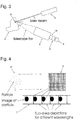
- The laser beam may be formed or shaped, e.g. by a suitable optical system, not shown, to have a cross-section having the shape of a thin bar or a thin straight line so that it illuminates a corresponding strip-shaped
area 2" of thetarget 3, i.e. of the object of interest, seeFig. 4 . The width of the strip-shaped area can correspond to the width of a subarea of interest. In particular it can correspond to or possibly slightly exceed, such as not exceeding by more than 25 % or better 10 %, the width or height of an area that is depicted on a single pixel, i.e. of an element subarea 2'. The lightsensitive surface 5 of thecamera 6 may then include only a single linear array ofpixels 7, i.e. pixels arranged along a line such as in one row or in one column. The pixels may as in conventional cameras have a rectangular or square shape but they could also be e.g. polygonal. The light from the illuminated strip-shaped area orthin line 2" on theobject 3, i.e. both reflected and scattered light from this area, is projected onto the linear pixel array in thecamera 6. The illuminated thin line may be oriented horizontally, vertically or in an arbitrary direction. - An area and/or an object can be scanned using a "bar-laser" as described above. The scanning can be made from a stationary geographical location using a detection device having pan and tilt functions as above. The scanning can alternatively be performed in the "moving" way described above. In the latter case, the detection device may optionally also have a pan function or a tilt function or both these functions.
- A laser beam formed to have a cross-section of a bar or a thin straight line as described above can also be used together with a conventional rectangular light
sensitive surface 5 having a plurality of horizontal rows and a plurality of vertical columns ofpixels 7 as seen inFig. 4 . Then the area of the lightsensitive surface 5 that corresponds to the illuminatedlinear area 2" on thetarget 3 is active for detection. In order to improve the speed of detection, a wavelengthdispersive device 19 of an edge or linear type, e.g. a cylinder-segment lens, a prism or a diffraction grating, seeFig. 3 , can be used. The wavelength dispersive device can be placed to deflect the collected reflected and scattered light output from the telescope 4 before it passes onto thearray 5 ofpixels 7. Thewavelength dispersive device 19 will for a proper positioning deflect the light so that light of different wavelengths hits different areas of thearray 5 of pixels. Then, usually light of the longest wavelengths hits a straight line of pixels at one end or side of the pixel array and light of the shortest wavelengths hits a straight line of pixels at the opposite end or side of the pixel array. Depending on the layout of the pixel array the information or signals obtained from a row of pixels, or a column, then represents/represent the intensity of light, scattered from the corresponding linear area of the target and having wavelengths only within a narrow wavelength band, i.e. the spectral response for a narrow wavelength band from the illuminated area of the target. - For investigating an
object 3, a laser beam which illuminates anarea 2 of theobject 3 corresponding to one ormore pixels 7 can be used. The spectrum is obtained in one measurement using spectral-spreading techniques or several measurements of one spectral band at a time. The beam is moved to the next subarea, that can be adjacent or non-adjacent, and another measurement is made. The image of thetotal object 3 is obtained by adding the responses from the individual subareas for which measurements have been made. - The detection system as described herein can be used in ordinary land-based vehicles but also in un-manned vehicles, e.g. in a UAV (Unmanned Aerial Vehicle) or in a naval vehicle.
- It should be understood herein and in the claims hereof that such terms as "top" and "bottom", "upwardly" and "downwordly", "width" and "height" and the like have been used for illustration purposes only, in order to provide a clear and understandable description and claiming of the invention.
- While specific embodiments of the invention have been illustrated and described herein, it is realized that numerous other embodiments may be envisaged and that numerous additional advantages, modifications and changes will readily occur to those skilled in the art without departing from the scope of the invention. Therefore, the invention in its broader aspects is not limited to the specific details, representative devices and illustrated examples shown and described herein. Accordingly, various modifications may be made without departing from the scope of the general inventive concept as defined by the appended claims. Numerous other embodiments may be envisaged without departing from the scope of the invention.
Claims (11)
- A method of detecting trace amounts of substances in a cluttered environment at stand-off distances for determining whether an area of detection on an object contains a hazardous substance, the area or detection being illuminated with light of a definite wavelength and the scattered light being analyzed in order to obtain a Raman-spectrum or a similar spectrum, the light scattered by the object being collected and concentrated by an optical system, in particular an optical system of the telescope type, depicting the image on a light detection device, characterized in
that the stand-off distance is ranging from 10 m to 100 m,
that the hazardous substance consists of molecules of a definite kind, in particular an explosive or a component of an explosive,
that the area of detection is divided into a plurality of smaller areas, called subareas, where the size of each subarea is comparable to the size of one or a few particles of molecules of the definite kind,
that a plurality of subareas is grouped to form a larger area and all individual subareas included in said plurality being simultaneously detected by means of the image from the optical system being depicted on the light detection device having several picture elements in a picture element array, wherein each picture element corresponds to an individual subarea, and
that in analyzing the scattered light, the detection signals from each of the individual picture elements are individually analyzed. - A method according to claim 1, characterized in that the collected light is filtered before it is detected so that light of only one wavelength range is analyzed.
- A method according to claim 2, characterized in that the band-pass wavelength of the optical filter is repetitiously changed and the analyzing of the scattered light is executed consecutively for each of a plurality of wavelength ranges.
- A method according to anyone of claims 1 - 3, characterized in that the illuminated area of the surface of the object is a line region or a strip-shaped area, in particular a strip-shaped area having a width corresponding to or slightly exceeding the width or the height of an area that is depicted on a single one of the individual picture element.
- A method according to claim 4, characterized in that the collected light is passed through a wavelength dispersive device of an edge or linear type having an edge or axis oriented so that the light collected from the line region hits parallel lines of the individual picture elements and the light collected from the line region hitting each of these lines includes only wavelengths of a corresponding individual wavelength band.
- A system of detecting trace amounts of substances in a cluttered environment at stand-off distances for determining whether an area of detection on an object contains a hazardous substance, comprising a light source for illuminating the area of detection with light of a definite wavelength, an optical system, in particular an optical system of the telescope type, for collecting and concentrating light from the illuminated area of the surface of the object, a light detection device receiving the collected and concentrated light, and an analysis unit for obtaining, from signals from the light detection device, a Raman-spectrum or a similar spectrum, characterized in
that the stand-off distance is ranging from 10 m to 100 m,
that the hazardous substance consists of molecules of a definite kind, in particular an explosive or a component of an explosive,
that the light detection device comprises a light sensitive surface including a plurality of individual picture elements arranged as a picture element array, each of the individual picture elements providing detection signals, and that the analysis unit is adapted to divide the area of detection into a plurality of smaller areas, called subareas, where the size of each subarea is comparable to the size of one or a few particles of molecules of the definite kind, group a plurality of subareas to form a larger area, and simultaneously detect all individual subareas included in said plurality by the image from the optical system being depicted on the light detection device and analyze individually the detection signals from each of the individual picture elements, wherein each picture element corresponds to an individual subarea. - A system according to claim 6, characterized by a filter for filtering the collected light before being received by the light detection device, so that light of only one wavelength range is detected.
- A system according to claim 7, characterized in that the filter is tunable so that the light detection device can detect light for each of a plurality of wavelength ranges consecutively by tuning the filter accordingly.
- A system according to anyone of claims 6-8, characterized in that the light source is arranged so that the illuminated area of the surface of the object is a line region or a strip-shaped area, in particular a strip-shaped area having a width corresponding to or slightly exceeding the width or the height of an area that is depicted on a single one of the individual picture element.
- A system according to claim 9, characterized by a wavelength dispersive device of an edge or linear type arranged so that the collected and concentrated light is passed therethrough, the wavelength dispersive device being an edge or linear type having an edge or axis oriented so that the light collected from the line region hits parallel lines of the individual picture elements and the light collected from the line region hitting each of these lines includes only wavelengths of a corresponding individual wavelength band.
- A system according to claim 10, characterized in that the wavelength dispersive device is a cylinder-segment lens, a prism or a diffraction grating.
Applications Claiming Priority (2)
| Application Number | Priority Date | Filing Date | Title |
|---|---|---|---|
| SE0802612A SE533454C2 (en) | 2008-12-18 | 2008-12-18 | Detection of small amounts of substances |
| PCT/SE2009/051440 WO2010071579A1 (en) | 2008-12-18 | 2009-12-17 | Detecting small amounts of substances |
Publications (3)
| Publication Number | Publication Date |
|---|---|
| EP2376880A1 EP2376880A1 (en) | 2011-10-19 |
| EP2376880A4 EP2376880A4 (en) | 2017-12-20 |
| EP2376880B1 true EP2376880B1 (en) | 2020-02-12 |
Family
ID=42269034
Family Applications (1)
| Application Number | Title | Priority Date | Filing Date |
|---|---|---|---|
| EP09833742.1A Active EP2376880B1 (en) | 2008-12-18 | 2009-12-17 | Method and system for detecting small amounts of substances |
Country Status (9)
| Country | Link |
|---|---|
| US (1) | US20120086939A1 (en) |
| EP (1) | EP2376880B1 (en) |
| JP (1) | JP2012513027A (en) |
| CN (1) | CN102257370A (en) |
| CA (1) | CA2745631A1 (en) |
| IL (1) | IL213267A0 (en) |
| SE (1) | SE533454C2 (en) |
| SG (1) | SG172151A1 (en) |
| WO (1) | WO2010071579A1 (en) |
Families Citing this family (11)
| Publication number | Priority date | Publication date | Assignee | Title |
|---|---|---|---|---|
| CA2872898A1 (en) | 2012-05-09 | 2013-11-14 | Seagate Technology Llc | Surface features mapping |
| CN103398990B (en) * | 2013-07-26 | 2016-08-24 | 中国地质大学(武汉) | The system and method for target is moved in a kind of quick identification |
| US10538325B1 (en) * | 2014-11-11 | 2020-01-21 | United Services Automobile Association | Utilizing unmanned vehicles to initiate and/or facilitate claims processing |
| CN104931477A (en) * | 2015-01-23 | 2015-09-23 | 成都鼎智汇科技有限公司 | High-precision Raman-spectrum explosive recognition instrument |
| CN105092485A (en) * | 2015-08-27 | 2015-11-25 | 泉州装备制造研究所 | Dangerous article detection method and device |
| US10139836B2 (en) | 2016-09-27 | 2018-11-27 | International Business Machines Corporation | Autonomous aerial point of attraction highlighting for tour guides |
| EP3803293A4 (en) * | 2018-05-30 | 2022-06-15 | Pendar Technologies, LLC | Methods and devices for standoff differential raman spectroscopy with increased eye safety and decreased risk of explosion |
| WO2019231512A1 (en) | 2018-05-30 | 2019-12-05 | Pendar Technologies, Llc | Methods and devices for standoff differential raman spectroscopy with increased eye safety and decreased risk of explosion |
| US11774353B2 (en) * | 2018-10-30 | 2023-10-03 | The Government Of The United States Of America, As Represented By The Secretary Of The Navy | Methods and apparatuses for biomimetic standoff detection of hazardous chemicals |
| JP7342629B2 (en) * | 2019-11-06 | 2023-09-12 | 株式会社島津製作所 | Sample component estimation method, sample component estimation device, sample component estimation program, learning method and learning program |
| CN112326626A (en) * | 2020-11-06 | 2021-02-05 | 公安部第三研究所 | Vehicle-mounted scanning type detection device for laser Raman spectrum analysis of pavement substances |
Family Cites Families (11)
| Publication number | Priority date | Publication date | Assignee | Title |
|---|---|---|---|---|
| CN85104863B (en) * | 1985-06-25 | 1988-05-04 | 株式会社岛津制作所 | Analysing method and device for element state |
| CN1162993A (en) * | 1994-08-20 | 1997-10-22 | 雷尼肖公司 | Detector for explosive substances |
| US6040906A (en) * | 1996-07-11 | 2000-03-21 | Harhay; Gregory P. | Resonance raman spectroscopy for identifying and quantitating biomatter, organic, and inorganic analytes |
| ATE514072T1 (en) * | 1997-05-05 | 2011-07-15 | Chemometec As | METHOD FOR DETERMINING PARTICLES IN A LIQUID SAMPLE |
| DE102004037064A1 (en) * | 2004-07-30 | 2006-02-16 | Abb Patent Gmbh | Method and device for functional testing of a field device before its initial commissioning |
| GB0426993D0 (en) * | 2004-12-09 | 2005-01-12 | Council Cent Lab Res Councils | Apparatus for depth-selective raman spectroscopy |
| WO2007123555A2 (en) * | 2005-07-14 | 2007-11-01 | Chemimage Corporation | Time and space resolved standoff hyperspectral ied explosives lidar detector |
| EP1949053A2 (en) | 2005-10-07 | 2008-07-30 | Chemimage Corporation | System and method for a chemical imaging threat assessor with a probe |
| US7796251B2 (en) * | 2006-03-22 | 2010-09-14 | Itt Manufacturing Enterprises, Inc. | Method, apparatus and system for rapid and sensitive standoff detection of surface contaminants |
| US7333190B1 (en) * | 2006-10-26 | 2008-02-19 | Itt Manufacturing Enterprises, Inc. | Raman interrogation of threat aerosols |
| GB0701477D0 (en) * | 2007-01-25 | 2007-03-07 | Renishaw Plc | Spectroscopic apparatus and methods |
-
2008
- 2008-12-18 SE SE0802612A patent/SE533454C2/en unknown
-
2009
- 2009-12-17 CN CN2009801510155A patent/CN102257370A/en active Pending
- 2009-12-17 WO PCT/SE2009/051440 patent/WO2010071579A1/en active Application Filing
- 2009-12-17 JP JP2011542067A patent/JP2012513027A/en not_active Withdrawn
- 2009-12-17 US US13/140,376 patent/US20120086939A1/en not_active Abandoned
- 2009-12-17 CA CA2745631A patent/CA2745631A1/en not_active Abandoned
- 2009-12-17 EP EP09833742.1A patent/EP2376880B1/en active Active
- 2009-12-17 SG SG2011043502A patent/SG172151A1/en unknown
-
2011
- 2011-05-31 IL IL213267A patent/IL213267A0/en unknown
Non-Patent Citations (1)
| Title |
|---|
| None * |
Also Published As
| Publication number | Publication date |
|---|---|
| EP2376880A4 (en) | 2017-12-20 |
| CN102257370A (en) | 2011-11-23 |
| CA2745631A1 (en) | 2010-06-24 |
| EP2376880A1 (en) | 2011-10-19 |
| US20120086939A1 (en) | 2012-04-12 |
| SE0802612A1 (en) | 2010-06-19 |
| WO2010071579A1 (en) | 2010-06-24 |
| SE533454C2 (en) | 2010-10-05 |
| IL213267A0 (en) | 2011-07-31 |
| SG172151A1 (en) | 2011-07-28 |
| JP2012513027A (en) | 2012-06-07 |
Similar Documents
| Publication | Publication Date | Title |
|---|---|---|
| EP2376880B1 (en) | Method and system for detecting small amounts of substances | |
| US8665433B2 (en) | Standoff explosives detector using deep-UV Raman spectroscopy | |
| US7692775B2 (en) | Time and space resolved standoff hyperspectral IED explosives LIDAR detection | |
| US7564546B2 (en) | Dynamic imaging of biological cells and other subjects | |
| US8379193B2 (en) | SWIR targeted agile raman (STAR) system for on-the-move detection of emplace explosives | |
| US20120062697A1 (en) | Hyperspectral imaging sensor for tracking moving targets | |
| EP2930496B1 (en) | Raman micro-spectrometry system and method for analyzing microscopic objects in a fluidic sample | |
| US20120062740A1 (en) | Hyperspectral imaging sensor for tracking moving targets | |
| US20090219525A1 (en) | System and method for portable raman spectroscopy | |
| US10969339B2 (en) | Optical readers | |
| US20120145906A1 (en) | Portable system for detecting explosives and a method of use thereof | |
| US20130135609A1 (en) | Targeted Agile Raman System for Detection of Unknown Materials | |
| WO2006083316A2 (en) | Multipoint method for identifying hazardous agents | |
| DE10314424A1 (en) | Warning system for real-time spatially resolved detection of icing of component or part surfaces employs diffuse infrared reflection spectrometry with a modified thermographic camera or infrared planar detector array | |
| US11067513B2 (en) | Simultaneous detection of multiple spectra of scattered radiation | |
| US8994934B1 (en) | System and method for eye safe detection of unknown targets | |
| Ponsardin et al. | Expanding applications for surface-contaminant sensing using the laser interrogation of surface agents (LISA) technique | |
| US10495515B2 (en) | Adaptive, very high resolution imaging spectrometer | |
| CA3148141A1 (en) | Raman spectroscopy for minerals identification | |
| Higdon et al. | Laser interrogation of surface agents (LISA) for chemical agent reconnaissance | |
| Bar | Raman-based point and proximal detection and imaging | |
| Gasser et al. | Stand-off hyperspectral imaging-towards mobile, high throughput remote chemical identification and quantification using chemometrics | |
| Boysworth et al. | Thomas H. Chyba, N. Scott Higdon, Wayne T. Armstrong, C. Ted Lobb, Patrick L. Ponsardin, Dale A. Richter, Brian T. Kelly, Quang Bui and Robert Babnick |
Legal Events
| Date | Code | Title | Description |
|---|---|---|---|
| PUAI | Public reference made under article 153(3) epc to a published international application that has entered the european phase |
Free format text: ORIGINAL CODE: 0009012 |
|
| 17P | Request for examination filed |
Effective date: 20110711 |
|
| AK | Designated contracting states |
Kind code of ref document: A1 Designated state(s): AT BE BG CH CY CZ DE DK EE ES FI FR GB GR HR HU IE IS IT LI LT LU LV MC MK MT NL NO PL PT RO SE SI SK SM TR |
|
| DAX | Request for extension of the european patent (deleted) | ||
| RA4 | Supplementary search report drawn up and despatched (corrected) |
Effective date: 20171122 |
|
| RIC1 | Information provided on ipc code assigned before grant |
Ipc: G01N 21/88 20060101ALI20171116BHEP Ipc: G01N 21/65 20060101ALI20171116BHEP Ipc: G01J 3/06 20060101AFI20171116BHEP Ipc: G01N 33/22 20060101ALI20171116BHEP |
|
| STAA | Information on the status of an ep patent application or granted ep patent |
Free format text: STATUS: EXAMINATION IS IN PROGRESS |
|
| 17Q | First examination report despatched |
Effective date: 20190320 |
|
| REG | Reference to a national code |
Ref country code: DE Ref legal event code: R079 Ref document number: 602009061185 Country of ref document: DE Free format text: PREVIOUS MAIN CLASS: G01J0003060000 Ipc: G01J0003320000 |
|
| GRAP | Despatch of communication of intention to grant a patent |
Free format text: ORIGINAL CODE: EPIDOSNIGR1 |
|
| STAA | Information on the status of an ep patent application or granted ep patent |
Free format text: STATUS: GRANT OF PATENT IS INTENDED |
|
| RIC1 | Information provided on ipc code assigned before grant |
Ipc: G01J 3/44 20060101ALI20190613BHEP Ipc: G01N 21/65 20060101ALI20190613BHEP Ipc: G01J 3/32 20060101AFI20190613BHEP |
|
| INTG | Intention to grant announced |
Effective date: 20190717 |
|
| GRAS | Grant fee paid |
Free format text: ORIGINAL CODE: EPIDOSNIGR3 |
|
| GRAA | (expected) grant |
Free format text: ORIGINAL CODE: 0009210 |
|
| STAA | Information on the status of an ep patent application or granted ep patent |
Free format text: STATUS: THE PATENT HAS BEEN GRANTED |
|
| AK | Designated contracting states |
Kind code of ref document: B1 Designated state(s): AT BE BG CH CY CZ DE DK EE ES FI FR GB GR HR HU IE IS IT LI LT LU LV MC MK MT NL NO PL PT RO SE SI SK SM TR |
|
| REG | Reference to a national code |
Ref country code: GB Ref legal event code: FG4D |
|
| REG | Reference to a national code |
Ref country code: CH Ref legal event code: EP |
|
| REG | Reference to a national code |
Ref country code: AT Ref legal event code: REF Ref document number: 1232744 Country of ref document: AT Kind code of ref document: T Effective date: 20200215 |
|
| REG | Reference to a national code |
Ref country code: IE Ref legal event code: FG4D |
|
| REG | Reference to a national code |
Ref country code: DE Ref legal event code: R096 Ref document number: 602009061185 Country of ref document: DE |
|
| PG25 | Lapsed in a contracting state [announced via postgrant information from national office to epo] |
Ref country code: NO Free format text: LAPSE BECAUSE OF FAILURE TO SUBMIT A TRANSLATION OF THE DESCRIPTION OR TO PAY THE FEE WITHIN THE PRESCRIBED TIME-LIMIT Effective date: 20200512 Ref country code: FI Free format text: LAPSE BECAUSE OF FAILURE TO SUBMIT A TRANSLATION OF THE DESCRIPTION OR TO PAY THE FEE WITHIN THE PRESCRIBED TIME-LIMIT Effective date: 20200212 |
|
| REG | Reference to a national code |
Ref country code: LT Ref legal event code: MG4D |
|
| REG | Reference to a national code |
Ref country code: NL Ref legal event code: MP Effective date: 20200212 |
|
| PG25 | Lapsed in a contracting state [announced via postgrant information from national office to epo] |
Ref country code: HR Free format text: LAPSE BECAUSE OF FAILURE TO SUBMIT A TRANSLATION OF THE DESCRIPTION OR TO PAY THE FEE WITHIN THE PRESCRIBED TIME-LIMIT Effective date: 20200212 Ref country code: GR Free format text: LAPSE BECAUSE OF FAILURE TO SUBMIT A TRANSLATION OF THE DESCRIPTION OR TO PAY THE FEE WITHIN THE PRESCRIBED TIME-LIMIT Effective date: 20200513 Ref country code: LV Free format text: LAPSE BECAUSE OF FAILURE TO SUBMIT A TRANSLATION OF THE DESCRIPTION OR TO PAY THE FEE WITHIN THE PRESCRIBED TIME-LIMIT Effective date: 20200212 Ref country code: SE Free format text: LAPSE BECAUSE OF FAILURE TO SUBMIT A TRANSLATION OF THE DESCRIPTION OR TO PAY THE FEE WITHIN THE PRESCRIBED TIME-LIMIT Effective date: 20200212 Ref country code: IS Free format text: LAPSE BECAUSE OF FAILURE TO SUBMIT A TRANSLATION OF THE DESCRIPTION OR TO PAY THE FEE WITHIN THE PRESCRIBED TIME-LIMIT Effective date: 20200612 Ref country code: BG Free format text: LAPSE BECAUSE OF FAILURE TO SUBMIT A TRANSLATION OF THE DESCRIPTION OR TO PAY THE FEE WITHIN THE PRESCRIBED TIME-LIMIT Effective date: 20200512 |
|
| PG25 | Lapsed in a contracting state [announced via postgrant information from national office to epo] |
Ref country code: NL Free format text: LAPSE BECAUSE OF FAILURE TO SUBMIT A TRANSLATION OF THE DESCRIPTION OR TO PAY THE FEE WITHIN THE PRESCRIBED TIME-LIMIT Effective date: 20200212 |
|
| PG25 | Lapsed in a contracting state [announced via postgrant information from national office to epo] |
Ref country code: CZ Free format text: LAPSE BECAUSE OF FAILURE TO SUBMIT A TRANSLATION OF THE DESCRIPTION OR TO PAY THE FEE WITHIN THE PRESCRIBED TIME-LIMIT Effective date: 20200212 Ref country code: PT Free format text: LAPSE BECAUSE OF FAILURE TO SUBMIT A TRANSLATION OF THE DESCRIPTION OR TO PAY THE FEE WITHIN THE PRESCRIBED TIME-LIMIT Effective date: 20200705 Ref country code: RO Free format text: LAPSE BECAUSE OF FAILURE TO SUBMIT A TRANSLATION OF THE DESCRIPTION OR TO PAY THE FEE WITHIN THE PRESCRIBED TIME-LIMIT Effective date: 20200212 Ref country code: LT Free format text: LAPSE BECAUSE OF FAILURE TO SUBMIT A TRANSLATION OF THE DESCRIPTION OR TO PAY THE FEE WITHIN THE PRESCRIBED TIME-LIMIT Effective date: 20200212 Ref country code: EE Free format text: LAPSE BECAUSE OF FAILURE TO SUBMIT A TRANSLATION OF THE DESCRIPTION OR TO PAY THE FEE WITHIN THE PRESCRIBED TIME-LIMIT Effective date: 20200212 Ref country code: SM Free format text: LAPSE BECAUSE OF FAILURE TO SUBMIT A TRANSLATION OF THE DESCRIPTION OR TO PAY THE FEE WITHIN THE PRESCRIBED TIME-LIMIT Effective date: 20200212 Ref country code: SK Free format text: LAPSE BECAUSE OF FAILURE TO SUBMIT A TRANSLATION OF THE DESCRIPTION OR TO PAY THE FEE WITHIN THE PRESCRIBED TIME-LIMIT Effective date: 20200212 Ref country code: DK Free format text: LAPSE BECAUSE OF FAILURE TO SUBMIT A TRANSLATION OF THE DESCRIPTION OR TO PAY THE FEE WITHIN THE PRESCRIBED TIME-LIMIT Effective date: 20200212 Ref country code: ES Free format text: LAPSE BECAUSE OF FAILURE TO SUBMIT A TRANSLATION OF THE DESCRIPTION OR TO PAY THE FEE WITHIN THE PRESCRIBED TIME-LIMIT Effective date: 20200212 |
|
| REG | Reference to a national code |
Ref country code: DE Ref legal event code: R097 Ref document number: 602009061185 Country of ref document: DE |
|
| REG | Reference to a national code |
Ref country code: AT Ref legal event code: MK05 Ref document number: 1232744 Country of ref document: AT Kind code of ref document: T Effective date: 20200212 |
|
| PLBE | No opposition filed within time limit |
Free format text: ORIGINAL CODE: 0009261 |
|
| STAA | Information on the status of an ep patent application or granted ep patent |
Free format text: STATUS: NO OPPOSITION FILED WITHIN TIME LIMIT |
|
| 26N | No opposition filed |
Effective date: 20201113 |
|
| PG25 | Lapsed in a contracting state [announced via postgrant information from national office to epo] |
Ref country code: AT Free format text: LAPSE BECAUSE OF FAILURE TO SUBMIT A TRANSLATION OF THE DESCRIPTION OR TO PAY THE FEE WITHIN THE PRESCRIBED TIME-LIMIT Effective date: 20200212 Ref country code: IT Free format text: LAPSE BECAUSE OF FAILURE TO SUBMIT A TRANSLATION OF THE DESCRIPTION OR TO PAY THE FEE WITHIN THE PRESCRIBED TIME-LIMIT Effective date: 20200212 |
|
| PG25 | Lapsed in a contracting state [announced via postgrant information from national office to epo] |
Ref country code: PL Free format text: LAPSE BECAUSE OF FAILURE TO SUBMIT A TRANSLATION OF THE DESCRIPTION OR TO PAY THE FEE WITHIN THE PRESCRIBED TIME-LIMIT Effective date: 20200212 Ref country code: SI Free format text: LAPSE BECAUSE OF FAILURE TO SUBMIT A TRANSLATION OF THE DESCRIPTION OR TO PAY THE FEE WITHIN THE PRESCRIBED TIME-LIMIT Effective date: 20200212 |
|
| REG | Reference to a national code |
Ref country code: CH Ref legal event code: PL |
|
| PG25 | Lapsed in a contracting state [announced via postgrant information from national office to epo] |
Ref country code: MC Free format text: LAPSE BECAUSE OF FAILURE TO SUBMIT A TRANSLATION OF THE DESCRIPTION OR TO PAY THE FEE WITHIN THE PRESCRIBED TIME-LIMIT Effective date: 20200212 |
|
| REG | Reference to a national code |
Ref country code: BE Ref legal event code: MM Effective date: 20201231 |
|
| PG25 | Lapsed in a contracting state [announced via postgrant information from national office to epo] |
Ref country code: LU Free format text: LAPSE BECAUSE OF NON-PAYMENT OF DUE FEES Effective date: 20201217 Ref country code: IE Free format text: LAPSE BECAUSE OF NON-PAYMENT OF DUE FEES Effective date: 20201217 |
|
| PG25 | Lapsed in a contracting state [announced via postgrant information from national office to epo] |
Ref country code: LI Free format text: LAPSE BECAUSE OF NON-PAYMENT OF DUE FEES Effective date: 20201231 Ref country code: CH Free format text: LAPSE BECAUSE OF NON-PAYMENT OF DUE FEES Effective date: 20201231 |
|
| PG25 | Lapsed in a contracting state [announced via postgrant information from national office to epo] |
Ref country code: TR Free format text: LAPSE BECAUSE OF FAILURE TO SUBMIT A TRANSLATION OF THE DESCRIPTION OR TO PAY THE FEE WITHIN THE PRESCRIBED TIME-LIMIT Effective date: 20200212 Ref country code: MT Free format text: LAPSE BECAUSE OF FAILURE TO SUBMIT A TRANSLATION OF THE DESCRIPTION OR TO PAY THE FEE WITHIN THE PRESCRIBED TIME-LIMIT Effective date: 20200212 Ref country code: CY Free format text: LAPSE BECAUSE OF FAILURE TO SUBMIT A TRANSLATION OF THE DESCRIPTION OR TO PAY THE FEE WITHIN THE PRESCRIBED TIME-LIMIT Effective date: 20200212 |
|
| PG25 | Lapsed in a contracting state [announced via postgrant information from national office to epo] |
Ref country code: MK Free format text: LAPSE BECAUSE OF FAILURE TO SUBMIT A TRANSLATION OF THE DESCRIPTION OR TO PAY THE FEE WITHIN THE PRESCRIBED TIME-LIMIT Effective date: 20200212 |
|
| PG25 | Lapsed in a contracting state [announced via postgrant information from national office to epo] |
Ref country code: BE Free format text: LAPSE BECAUSE OF NON-PAYMENT OF DUE FEES Effective date: 20201231 |
|
| PGFP | Annual fee paid to national office [announced via postgrant information from national office to epo] |
Ref country code: GB Payment date: 20231219 Year of fee payment: 15 |
|
| PGFP | Annual fee paid to national office [announced via postgrant information from national office to epo] |
Ref country code: FR Payment date: 20231220 Year of fee payment: 15 Ref country code: DE Payment date: 20231019 Year of fee payment: 15 |