EP2376814B1 - Method for the operation of a transmission device - Google Patents
Method for the operation of a transmission device Download PDFInfo
- Publication number
- EP2376814B1 EP2376814B1 EP10700250.3A EP10700250A EP2376814B1 EP 2376814 B1 EP2376814 B1 EP 2376814B1 EP 10700250 A EP10700250 A EP 10700250A EP 2376814 B1 EP2376814 B1 EP 2376814B1
- Authority
- EP
- European Patent Office
- Prior art keywords
- transmission
- shift element
- transmission device
- locking shift
- operating state
- Prior art date
- Legal status (The legal status is an assumption and is not a legal conclusion. Google has not performed a legal analysis and makes no representation as to the accuracy of the status listed.)
- Active
Links
Images


Classifications
-
- F—MECHANICAL ENGINEERING; LIGHTING; HEATING; WEAPONS; BLASTING
- F16—ENGINEERING ELEMENTS AND UNITS; GENERAL MEASURES FOR PRODUCING AND MAINTAINING EFFECTIVE FUNCTIONING OF MACHINES OR INSTALLATIONS; THERMAL INSULATION IN GENERAL
- F16H—GEARING
- F16H61/00—Control functions within control units of change-speed- or reversing-gearings for conveying rotary motion ; Control of exclusively fluid gearing, friction gearing, gearings with endless flexible members or other particular types of gearing
- F16H61/04—Smoothing ratio shift
- F16H61/0403—Synchronisation before shifting
-
- B—PERFORMING OPERATIONS; TRANSPORTING
- B60—VEHICLES IN GENERAL
- B60W—CONJOINT CONTROL OF VEHICLE SUB-UNITS OF DIFFERENT TYPE OR DIFFERENT FUNCTION; CONTROL SYSTEMS SPECIALLY ADAPTED FOR HYBRID VEHICLES; ROAD VEHICLE DRIVE CONTROL SYSTEMS FOR PURPOSES NOT RELATED TO THE CONTROL OF A PARTICULAR SUB-UNIT
- B60W10/00—Conjoint control of vehicle sub-units of different type or different function
- B60W10/04—Conjoint control of vehicle sub-units of different type or different function including control of propulsion units
- B60W10/08—Conjoint control of vehicle sub-units of different type or different function including control of propulsion units including control of electric propulsion units, e.g. motors or generators
-
- F—MECHANICAL ENGINEERING; LIGHTING; HEATING; WEAPONS; BLASTING
- F16—ENGINEERING ELEMENTS AND UNITS; GENERAL MEASURES FOR PRODUCING AND MAINTAINING EFFECTIVE FUNCTIONING OF MACHINES OR INSTALLATIONS; THERMAL INSULATION IN GENERAL
- F16H—GEARING
- F16H3/00—Toothed gearings for conveying rotary motion with variable gear ratio or for reversing rotary motion
- F16H3/44—Toothed gearings for conveying rotary motion with variable gear ratio or for reversing rotary motion using gears having orbital motion
- F16H3/62—Gearings having three or more central gears
- F16H3/66—Gearings having three or more central gears composed of a number of gear trains without drive passing from one train to another
-
- F—MECHANICAL ENGINEERING; LIGHTING; HEATING; WEAPONS; BLASTING
- F16—ENGINEERING ELEMENTS AND UNITS; GENERAL MEASURES FOR PRODUCING AND MAINTAINING EFFECTIVE FUNCTIONING OF MACHINES OR INSTALLATIONS; THERMAL INSULATION IN GENERAL
- F16H—GEARING
- F16H61/00—Control functions within control units of change-speed- or reversing-gearings for conveying rotary motion ; Control of exclusively fluid gearing, friction gearing, gearings with endless flexible members or other particular types of gearing
-
- F—MECHANICAL ENGINEERING; LIGHTING; HEATING; WEAPONS; BLASTING
- F16—ENGINEERING ELEMENTS AND UNITS; GENERAL MEASURES FOR PRODUCING AND MAINTAINING EFFECTIVE FUNCTIONING OF MACHINES OR INSTALLATIONS; THERMAL INSULATION IN GENERAL
- F16H—GEARING
- F16H3/00—Toothed gearings for conveying rotary motion with variable gear ratio or for reversing rotary motion
- F16H3/44—Toothed gearings for conveying rotary motion with variable gear ratio or for reversing rotary motion using gears having orbital motion
- F16H2003/442—Toothed gearings for conveying rotary motion with variable gear ratio or for reversing rotary motion using gears having orbital motion comprising two or more sets of orbital gears arranged in a single plane
-
- F—MECHANICAL ENGINEERING; LIGHTING; HEATING; WEAPONS; BLASTING
- F16—ENGINEERING ELEMENTS AND UNITS; GENERAL MEASURES FOR PRODUCING AND MAINTAINING EFFECTIVE FUNCTIONING OF MACHINES OR INSTALLATIONS; THERMAL INSULATION IN GENERAL
- F16H—GEARING
- F16H3/00—Toothed gearings for conveying rotary motion with variable gear ratio or for reversing rotary motion
- F16H3/44—Toothed gearings for conveying rotary motion with variable gear ratio or for reversing rotary motion using gears having orbital motion
- F16H2003/445—Toothed gearings for conveying rotary motion with variable gear ratio or for reversing rotary motion using gears having orbital motion without permanent connection between the input and the set of orbital gears
-
- F—MECHANICAL ENGINEERING; LIGHTING; HEATING; WEAPONS; BLASTING
- F16—ENGINEERING ELEMENTS AND UNITS; GENERAL MEASURES FOR PRODUCING AND MAINTAINING EFFECTIVE FUNCTIONING OF MACHINES OR INSTALLATIONS; THERMAL INSULATION IN GENERAL
- F16H—GEARING
- F16H61/00—Control functions within control units of change-speed- or reversing-gearings for conveying rotary motion ; Control of exclusively fluid gearing, friction gearing, gearings with endless flexible members or other particular types of gearing
- F16H61/04—Smoothing ratio shift
- F16H61/0403—Synchronisation before shifting
- F16H2061/0407—Synchronisation before shifting by control of clutch in parallel torque path
-
- F—MECHANICAL ENGINEERING; LIGHTING; HEATING; WEAPONS; BLASTING
- F16—ENGINEERING ELEMENTS AND UNITS; GENERAL MEASURES FOR PRODUCING AND MAINTAINING EFFECTIVE FUNCTIONING OF MACHINES OR INSTALLATIONS; THERMAL INSULATION IN GENERAL
- F16H—GEARING
- F16H61/00—Control functions within control units of change-speed- or reversing-gearings for conveying rotary motion ; Control of exclusively fluid gearing, friction gearing, gearings with endless flexible members or other particular types of gearing
- F16H61/20—Preventing gear creeping ; Transmission control during standstill, e.g. hill hold control
- F16H2061/205—Hill hold control, e.g. with torque converter or a friction device slightly engaged to keep vehicle stationary
-
- F—MECHANICAL ENGINEERING; LIGHTING; HEATING; WEAPONS; BLASTING
- F16—ENGINEERING ELEMENTS AND UNITS; GENERAL MEASURES FOR PRODUCING AND MAINTAINING EFFECTIVE FUNCTIONING OF MACHINES OR INSTALLATIONS; THERMAL INSULATION IN GENERAL
- F16H—GEARING
- F16H2200/00—Transmissions for multiple ratios
- F16H2200/003—Transmissions for multiple ratios characterised by the number of forward speeds
- F16H2200/006—Transmissions for multiple ratios characterised by the number of forward speeds the gear ratios comprising eight forward speeds
-
- F—MECHANICAL ENGINEERING; LIGHTING; HEATING; WEAPONS; BLASTING
- F16—ENGINEERING ELEMENTS AND UNITS; GENERAL MEASURES FOR PRODUCING AND MAINTAINING EFFECTIVE FUNCTIONING OF MACHINES OR INSTALLATIONS; THERMAL INSULATION IN GENERAL
- F16H—GEARING
- F16H2200/00—Transmissions for multiple ratios
- F16H2200/20—Transmissions using gears with orbital motion
- F16H2200/2002—Transmissions using gears with orbital motion characterised by the number of sets of orbital gears
- F16H2200/2012—Transmissions using gears with orbital motion characterised by the number of sets of orbital gears with four sets of orbital gears
-
- F—MECHANICAL ENGINEERING; LIGHTING; HEATING; WEAPONS; BLASTING
- F16—ENGINEERING ELEMENTS AND UNITS; GENERAL MEASURES FOR PRODUCING AND MAINTAINING EFFECTIVE FUNCTIONING OF MACHINES OR INSTALLATIONS; THERMAL INSULATION IN GENERAL
- F16H—GEARING
- F16H2200/00—Transmissions for multiple ratios
- F16H2200/20—Transmissions using gears with orbital motion
- F16H2200/203—Transmissions using gears with orbital motion characterised by the engaging friction means not of the freewheel type, e.g. friction clutches or brakes
- F16H2200/2046—Transmissions using gears with orbital motion characterised by the engaging friction means not of the freewheel type, e.g. friction clutches or brakes with six engaging means
-
- F—MECHANICAL ENGINEERING; LIGHTING; HEATING; WEAPONS; BLASTING
- F16—ENGINEERING ELEMENTS AND UNITS; GENERAL MEASURES FOR PRODUCING AND MAINTAINING EFFECTIVE FUNCTIONING OF MACHINES OR INSTALLATIONS; THERMAL INSULATION IN GENERAL
- F16H—GEARING
- F16H2200/00—Transmissions for multiple ratios
- F16H2200/20—Transmissions using gears with orbital motion
- F16H2200/203—Transmissions using gears with orbital motion characterised by the engaging friction means not of the freewheel type, e.g. friction clutches or brakes
- F16H2200/2064—Transmissions using gears with orbital motion characterised by the engaging friction means not of the freewheel type, e.g. friction clutches or brakes using at least one positive clutch, e.g. dog clutch
-
- F—MECHANICAL ENGINEERING; LIGHTING; HEATING; WEAPONS; BLASTING
- F16—ENGINEERING ELEMENTS AND UNITS; GENERAL MEASURES FOR PRODUCING AND MAINTAINING EFFECTIVE FUNCTIONING OF MACHINES OR INSTALLATIONS; THERMAL INSULATION IN GENERAL
- F16H—GEARING
- F16H2200/00—Transmissions for multiple ratios
- F16H2200/20—Transmissions using gears with orbital motion
- F16H2200/2094—Transmissions using gears with orbital motion using positive clutches, e.g. dog clutches
-
- F—MECHANICAL ENGINEERING; LIGHTING; HEATING; WEAPONS; BLASTING
- F16—ENGINEERING ELEMENTS AND UNITS; GENERAL MEASURES FOR PRODUCING AND MAINTAINING EFFECTIVE FUNCTIONING OF MACHINES OR INSTALLATIONS; THERMAL INSULATION IN GENERAL
- F16H—GEARING
- F16H2306/00—Shifting
- F16H2306/40—Shifting activities
- F16H2306/44—Removing torque from current gears
-
- F—MECHANICAL ENGINEERING; LIGHTING; HEATING; WEAPONS; BLASTING
- F16—ENGINEERING ELEMENTS AND UNITS; GENERAL MEASURES FOR PRODUCING AND MAINTAINING EFFECTIVE FUNCTIONING OF MACHINES OR INSTALLATIONS; THERMAL INSULATION IN GENERAL
- F16H—GEARING
- F16H2306/00—Shifting
- F16H2306/40—Shifting activities
- F16H2306/46—Uncoupling of current gear
Landscapes
- Engineering & Computer Science (AREA)
- General Engineering & Computer Science (AREA)
- Mechanical Engineering (AREA)
- Chemical & Material Sciences (AREA)
- Combustion & Propulsion (AREA)
- Transportation (AREA)
- Control Of Transmission Device (AREA)
Description
Die Erfindung betrifft ein Verfahren zum Betreiben einer Getriebevorrichtung gemäß der im Oberbegriff des Patentanspruches 1 näher definierten Art, wie aus der
Aus der Praxis bekannte und als Automatgetriebe ausgeführte Getriebevorrichtungen sind zum Darstellen verschiedener Übersetzungen mit Schaltelementen ausgeführt, über welche jeweils ein anliegendes Drehmoment reibschlüssig übertragbar ist. Bei Vorliegen einer Anforderung zum Darstellen einer definierten Übersetzung werden jeweils wenigstens eines oder mehrere der reibschlüssigen Schaltelemente aus dem Kraftfluss einer Getriebevorrichtung abgeschaltet, während wenigstens ein weiteres oder weitere reibschlüssige Schaltelemente zur Darstellung der angeforderten Übersetzung in den Kraftfluss der Getriebevorrichtung zugeschaltet werden. Während des Zuschaltvorganges eines reibschlüssigen Schaltelementes sind zur Gewährleistung eines gewünschten Schaltkomforts sowie einer zugkraftunterbrechungsfreien Schaltung keine besonderen Synchronisiermaßnahmen erforderlich, da ein angestrebter Schaltkomfort und auch eine zugkräftunterbrechungsfreie Schaltung mittels reibschlüssigen Schaltelementen bei definierten Anpressdrücken innerhalb eines breiten Differenzdrehzahlbandes realisierbar sind.From the practice known and designed as an automatic transmission gear devices are designed to represent various translations with switching elements, via which in each case an applied torque is frictionally transferable. In the presence of a request for representing a defined translation, at least one or more of the frictional switching elements are switched off from the power flow of a transmission device, while at least one further or further frictional switching elements are switched to represent the requested translation in the power flow of the transmission device. During the connection process of a frictional shift element to ensure a desired shift comfort and a traction interruption-free circuit no special synchronization measures are required because a desired shift comfort and a zugkräftunterbrechungsfreie circuit by means of frictional shift elements at defined contact pressures within a wide differential speed range can be realized.
Da derartige Getriebevorrichtungen in an sich bekannter Art und Weise auf Grund von im Bereich von geöffneten reibschlüssigen Schaltelementen auftretenden Schleppverlusten mit nur unzureichenden Wirkungsgraden betreibbar sind, werden bestimmte reibschlüssige Schaltelemente durch formschlüssige Schaltelemente ersetzt. Bei solchen Automatgetrieben, die sowohl mit reibschlüssigen Schaltelementen als auch mit mindestens einem formschlüssigen Schaltelement und mit einer entsprechenden Radsatzkonstfuktion ausgeführt sind, ist zur Umsetzung einer definierten Schaltanforderung mindestens ein formschlüssiges Schaltelement in einen Kraftfluss einer Getriebevorrichtung zuzuschalten.Since such transmission devices are operable in known manner due to occurring in the range of open frictional shift elements drag losses with only insufficient efficiencies, certain frictional switching elements are replaced by positive switching elements. In such automatic transmissions, which are designed both with frictionally engaged shifting elements and with at least one interlocking shifting element and with a corresponding wheelset configuration, at least one is required to implement a defined shifting request to connect a positive switching element in a power flow of a transmission device.
Nachteilhafterweise sind formschlüssige Schaltelemente mit oder ohne zusätzliche konstruktive Synchronisiereinrichtungen im Vergleich zu reibschlüssigen Schaltelementen nur bei sehr geringen Differenzdrehzahlen, d. h. nahe ihrer Synchrondrehzahl, komfortabel schaltbar, wodurch ein Betrieb eines mit wenigstens einem formschlüssigen Schaltelement ausgeführten und als Automatgetriebe ausgebildeten Getriebevorrichtung zumindest während der Durchführung bestimmter Schaltungen, an welchen ein formschlüssiges Schaltelement beteiligt ist, in unerwünschtem Umfang beeinträchtigt ist. Eine angeforderte Schaltung ist unter Umständen erst nach Ablauf einer unerwünscht langen Schaltzeit abschließbar, da vor dem Schließen des an der angeforderten Schaltung beteiligten formschlüssigen Schaltelementes sich die Differenzdrehzahl im Bereich des formschlüssigen Schaltelementes auf einen Betrag einstellen muss, zu dem das formschlüssige Schaltelement in seinen geschlossenen Betriebszustand überführbar ist. Des Weiteren ist im Bereich eines zuzuschaltenden formschlüssigen Schaltelementes vor dem Erreichen des geschlossenen Betriebszustandes keine Lastübernahme wie bei einem reibschlüssigen Schaltelement möglich, womit Schaltungen mit formschlüssigen Schaltelementen nicht zugkraftunterbrechungsfrei durchführbar sind.Disadvantageously, positive-locking shifting elements with or without additional constructive synchronizing devices are only possible at very low differential rotational speeds, in comparison to frictional shifting elements. H. close to their synchronous speed, comfortably switchable, whereby an operation of a running with at least one interlocking switching element and designed as an automatic transmission device is at least during the implementation of certain circuits in which a form-locking switching element is involved, affected to an undesirable extent. A requested circuit may be closed only after expiration of an undesirably long switching time, as before the closing of the form-fitting switching element involved in the requested circuit, the differential speed must set in the form of interlocking switching element to an amount to which the positive switching element in its closed operating state is convertible. Furthermore, in the region of an interlocking interlocking switching element before reaching the closed operating state no load transfer as in a frictional switching element is possible, which circuits with positive switching elements are not zugkraftunterbrechungsfrei feasible.
Zusätzliche konstruktive Maßnahmen zum Synchronisieren von formschlüssigen Schaltelementen von Getriebevorrichtungen, um eine angeforderte Schaltung zugkraftunterbrechungsfrei innerhalb einer akzeptablen Schaltzeit bei gleichzeitig hohem Schaltkomfort durchführen zu können, erhöhen jedoch unerwünschterweise sowohl die Fertigungskosten als auch den Bauraumbedarf der Getriebevorrichtungen.However, additional design measures for synchronizing positive switching elements of transmission devices in order to perform a requested circuit traction interruption free within an acceptable switching time at the same time high comfort, but increase undesirably both the manufacturing costs and the space requirement of the transmission devices.
Der vorliegenden Erfindung liegt daher die Aufgabe zu Grunde, ein Verfahren zum Betreiben einer Getriebevorrichtung zur Verfügung zu stellen, mittels welchem Schaltungen in Getriebevorrichtungen, an welchen wenigstens ein formschlüssiges Schaltelement beteiligt ist, mit hohem Schaltkomfort kostengünstig und ohne zusätzlichen Bauraumbedarf einer Getriebevorrichtung innerhalb vordefinierter Schaltzeiten und vorzugsweise ohne Zugkraftunterbrechung durchführbar sind.The present invention is therefore based on the object to provide a method for operating a transmission device, by means of which circuits in transmission devices, in which at least one form-fitting switching element is involved, with high comfort and cost without additional space requirements of a transmission device within predefined switching times and preferably without interruption of traction are feasible.
Erfindungsgemäß wird diese Aufgabe mit einem Verfahren mit den Merkmalen des Patentanspruches 1 gelöst.According to the invention this object is achieved by a method having the features of
Bei dem erfindungsgemäßen Verfahren zum Betreiben einer Getriebevorrichtung mit mehreren reibschlüssigen Schaltelementen und wenigstens einem formschlüssigen Schaltelement zum Darstellen verschiedener Übersetzungen wird das formschlüssige Schaltelement bei einer angeforderten Schaltung, während der das formschlüssige Schaltelement aus einem geöffneten in einen geschlossenen Betriebszustand überführt wird, durch Anheben der Übertragungsfähigkeit wenigstens eines reibschlüssigen Schaltelementes, welches weder zur Darstellung des aktuellen Betriebszustands der Getriebevorrichtung noch zur Darstellung der einzulegenden Übersetzung in den Kraftfluss der Getriebevorrichtung zuzuschalten ist, wenigstens annähernd synchronisiert.In the method according to the invention for operating a transmission device with a plurality of frictionally engaged shift elements and at least one interlocking shift element for displaying various ratios, the interlocking shift element is at least requested by a boosted transmission capability at a requested shift during which the interlocking shift element is transferred from an open to a closed mode a frictionally engaged switching element, which is zuzuschalten neither to represent the current operating state of the transmission device nor to represent the einzulegenden translation into the power flow of the transmission device, at least approximately synchronized.
Damit wird das wenigstens eine formschlüssige Schaltelement ohne zusätzliche konstruktive Synchronisierungseinrichtungen durch einen entsprechenden Betrieb von in einer Getriebevorrichtung bereits vorhandenen Einrichtungen, d. h. vorliegend mittels wenigstens einem reibschlüssigen Schaltelement, effektiv, kostengünstig und mit geringem Bauraumbedarf der Getriebevorrichtung während einer angeforderten Schaltung vor dem Schließvorgang synchronisiert, so dass Schaltungen mit hohem Schaltkomfort mit gleichzeitig akzeptablen Schaltzeiten sowie vorzugsweise zugkraftunterbrechungsfrei durchführbar sind.Thus, the at least one interlocking switching element without additional constructive synchronization means by a corresponding operation of existing devices in a transmission device, ie in the present case synchronized by means of at least one frictional switching element, effectively, inexpensively and with low space requirements of the transmission device during a requested circuit before closing, so that circuits with high switching comfort with acceptable switching times and preferably zugkraftunterbrechungsfrei are feasible.
Bei dem Verfahren nach der Erfindung wird das formschlüssige Schaltelement in wenigstens annähernd synchronisiertem Betriebszustand in seinen geschlossenen Betriebszustand überführt, womit ein hoher Schaltkomfort bei gleichzeitig geringen mechanischen Belastungen im Bereich des formschlüssigen Schaltelementes erreicht wird.In the method according to the invention, the form-locking switching element is transferred in at least approximately synchronized operating state in its closed operating state, whereby a high switching comfort is achieved with low mechanical loads in the field of interlocking switching element.
Die Belastungen für die einzelnen Baugruppen einer Getriebevorrichtung sind bei einer weiteren vorteilhaften Variante des erfindungsgemäßen Verfahrens bei gleichzeitig hohem Schaltkomfort dadurch reduziert, dass die Übertragungsfähigkeit wenigstens eines weiteren reibschlüssigen Schaltelementes, welches weder an dem Synchronisiervorgang des formschlüssigen Schaltelementes noch zur Darstellung des aktuellen Betriebszustands der Getriebevorrichtung oder zur Darstellung der einzulegenden Übersetzung beteiligt ist, vor dem durch das Anheben der Übertragungsfähigkeit des reibschlüssigen Schaltelementes bewirkten Synchronisieren des formschlüssigen Schaltelementes angehoben und ein mit einem Getriebeausgang wirkverbundener Abtrieb eines mit der Getriebevorrichtung ausgebildeten Fahrzeuges abgebremst wird.The loads for the individual components of a transmission device are reduced in a further advantageous variant of the method according to the invention with high comfort that the transfer capability of at least one other frictional switching element, which neither on the synchronization of the positive switching element nor to represent the current operating state of the transmission device or involved in the representation of the gear ratio to be engaged, raised in front of the synchronizing of the interlocking switching element caused by the raising of the transmissibility of the frictional switching element, and decelerating an output of a vehicle-mounted transmission with a transmission output.
Bei einer Rückwärtsfahrt eines mit der Getriebevorrichtung ausgeführten Fahrzeuges mit einer Fahrzeuggeschwindigkeit größer als ein vordefinierter Schwellwert, einem Neutralbetriebszustand der Getriebevorrichtung, zu dem der Kraftfluss in der Getriebevorrichtung im Wesentlichen unterbrochen ist, und bei Vorliegen einer Anforderung zum Einlegen einer Übersetzung für Vorwärtsfahrt in der Getriebevorrichtung, zu deren Darstellung das formschlüssige Schaltelement in einen geschlossenen Betriebszustand zu überführen ist, wird der mit dem Abtrieb wirkverbundene Getriebeausgang durch Anheben der Übertragungsfähigkeit des weiteren reibschlüssigen Schaltelementes bei einer weiteren vorteilhaften Variante des Verfahrens nach der Erfindung abgebremst, um die angeforderte Schaltung mit hohem Schaltkomfort bei gleichzeitig geringen mechanischen Belastungen im Bereich des formschlüssigen Schaltelementes durchführen zu können.During reverse travel of a vehicle implemented with the transmission device with a vehicle speed greater than a predefined threshold value, a neutral operating state of the transmission device to which the power flow in the transmission device is substantially interrupted, and in the presence of a request for engaging a ratio for forward drive in the transmission device, To represent the interlocking switching element is to be converted into a closed operating state, the output connected to the output transmission output is slowed down by raising the transmission capacity of the further frictional switching element in a further advantageous variant of the method according to the invention to the requested circuit with high comfort at the same time low be able to perform mechanical loads in the region of the positive switching element.
Eine angeforderte Schaltung, während der ein formschlüssiges Schaltelement in den Kraftfluss einer Getriebevorrichtung zuzuschalten ist, wird mittels einer weiteren Variante des Verfahrens nach der Erfindung mit hohem Schaltkomfort bei gleichzeitig geringen mechanischen Belastungen im Bereich des formschlüssigen Schaltelementes durchgeführt, da bei einer Vorwärtsfahrt eines mit der Getriebevorrichtung ausgeführten Fahrzeuges und bei einer Fahrzeuggeschwindigkeit kleiner als ein vordefinierter Schwellwert, einem Neutralbetriebszustand der Getriebevorrichtung, zu dem der Kraftfluss in der Getriebevorrichtung im Wesentlichen unterbrochen ist und bei Vorliegen einer Anforderung zum Einlegen einer Übersetzung für Vorwärtsfahrt in der Getriebevorrichtung, zu deren Darstellung das formschlüssige Schaltelement in einen geschlossenen Betriebszustand zu überführen ist, das formschlüssige Schaltelement durch Anheben der Übertragungsfähigkeit eines reibschlüssigen Schaltelementes, dessen Übertragungsfähigkeit während der Darstellung der angeforderten Übersetzung im Wesentlichen Null ist, wenigstens annähernd synchronisiert und anschließend geschlossen wird, wobei daran anschließend ein den Kraftfluss in der Getriebevorrichtung herstellendes reibschlüssiges Schaltelement zugeschaltet wird.A requested circuit during which a positive switching element is zuzuschalten in the power flow of a transmission device is performed by means of a further variant of the method according to the invention with high switching comfort with low mechanical loads in the field of interlocking switching element, as in a forward drive one with the transmission device running vehicle and at a vehicle speed less than a predefined threshold, a neutral operating state of the transmission device to which the power flow in the transmission device is substantially interrupted and in the presence of a request for engaging a ratio for forward drive in the transmission device, to represent the interlocking switching element in to transfer a closed operating state, the interlocking switching element by raising the transmission capacity of a frictional switching element, its transmission capability is substantially zero during the presentation of the requested translation, at least approximately synchronized and then closed, wherein subsequently a frictional switching element producing the power flow in the transmission device is switched on.
Bei einer Rückwärtsfahrt mit einer Fahrzeuggeschwindigkeit kleiner als der Schwellwert wird das formschlüssige Schaltelement durch Anheben der Übertragungsfähigkeit des reibschlüssigen Schaltelementes wenigstens annähernd synchronisiert und anschließend geschlossen und wiederum daran anschließend ein den Kraftfluss in der Getriebevorrichtung herstellendes reibschlüssiges Schaltelement bei einer weiteren vorteilhaften Variante des Verfahrens nach der Erfindung zugeschaltet, um die angeforderte Schaltung mit hohem Komfort bei gleichzeitig geringen mechanischen Belastungen im Bereich des formschlüssigen Schaltelementes durchführen zu können.In a reverse drive with a vehicle speed less than the threshold value, the positive switching element is at least approximately synchronized by increasing the transmissibility of the frictional switching element and then closed and then subsequently a force flow in the transmission device producing frictional engagement element in a further advantageous variant of the method according to the invention switched to perform the requested circuit with high comfort at the same time low mechanical loads in the field of positive switching element.
Bei Vorliegen einer Anforderung für eine vorzugsweise zugkraftunterbrechungsfreie Zughochschaltung, während welcher das formschlüssige Schaltelement zur Darstellung der angeforderten Ziel-Übersetzung zuzuschalten ist, wird das formschlüssige Schaltelement bei einer weiteren vorteilhaften Variante des erfindungsgemäßen Verfahrens vor der Zuschaltung durch Anheben der Übertragungsfähigkeit wenigstens eines reibschlüssigen Schaltelementes, welches weder zur Darstellung des aktuellen Betriebszustandes in der Getriebevorrichtung noch zur Darstellung des angeforderten Betriebszustandes in den Kraftfluss der Getriebevorrichtung zuzuschalten ist, wenigstens annähernd synchronisiert.In the presence of a request for a preferably zugkraftunterbrechungsfreie train upshift, during which the positive switching element is zuzuschalten to represent the requested target translation, the positive switching element in a further advantageous variant of the method according to the invention before the connection by raising the transmission capacity of at least one frictional switching element, which is not switched on at least approximately synchronized to represent the current operating state in the transmission device nor to display the requested operating state in the power flow of the transmission device.
Die Übertragungsfähigkeit des zur Darstellung der Ist-Übersetzung vorgesehenen zugeschalteten reibschlüssigen Schaltelementes wird bei Vorliegen einer Getriebeeingangsdrehzahl, die wenigstens annähernd einer zu der angeforderten Ziel-Übersetzung äquivalenten Synchrondrehzahl entspricht, bei einer weiteren vorteilhaften Variante des erfindungsgemäßen Verfahrens abgesenkt, während das zuzuschaltende formschlüssige Schaltelement in seinen geschlossenen Betriebszustand überführt wird.The transmission capability of the provided for displaying the actual ratio switched frictional switching element is lowered in the presence of a transmission input speed which corresponds at least approximately to the required target translation equivalent synchronous speed in a further advantageous variant of the method according to the invention, while zuzuschaltende positive switching element in his closed operating state is transferred.
Bei einer weiteren vorteilhaften Variante des erfindungsgemäßen Verfahrens ist eine angeforderte Zughochschaltung dadurch zugkraftunterbrechungsfrei durchführbar, dass die Übertragungsfähigkeit eines zur Darstellung der Ist-Übersetzung in den Kraftfluss zugeschalteten reibschlüssigen Schaltelementes bei Vorliegen der Anforderung für die Zughochschaltung ausgehend von der Ist-Übersetzung in Richtung der Ziel-Übersetzung reduziert wird und das zum Synchronisieren des zuzuschaltenden formschlüssigen Schaltelements vorgesehene reibschlüssige Schaltelement für die Erhöhung der Übertragungsfähigkeit wenigstens annähernd vorbereitet ist.In a further advantageous variant of the method according to the invention, a requested upshift can be carried out without interruption of traction, that the transmission capability of a frictionally engaged shifting element connected to the force transmission for representing the actual transmission in the force flow is dependent on the actual transmission in the direction of the target upshift. Translation is reduced and provided for synchronizing the zuzuschaltenden positive switching element provided frictional switching element for increasing the transmission capacity is at least approximately.
Die Übertragungsfähigkeit des zur Darstellung der Ist-Übersetzung zugeschalteten reibschlüssigen Schaltelementes wird bei einer weiteren vorteilhaften Variante des erfindungsgemäßen Verfahrens wenigstens annähernd auf Null abgesenkt, wenn die Getriebeeingangsdrehzahl aufgrund der Übertragungsfähigkeit des zum Synchronisieren zuzuschaltenden formschlüssigen Schaltelementes vorgesehenen reibschlüssigen Schaltelementes von der zur Ist-Übersetzung äquivalenten Drehzahl in Richtung der zur Ziel-Übersetzung äquivalenten Drehzahl geführt wird. Damit wird auf einfache Art und Weise gewährleistet, dass eine angeforderte Zughochschaltung zugkraftunterbrechungsfrei bei gelichzeitig hohem Schaltkomfort durchführbar ist.In a further advantageous variant of the method according to the invention, the transmission capability of the frictional shift element connected to display the actual transmission is reduced at least approximately to zero, if the transmission input rotational speed is equivalent to the rotational speed equivalent to the actual transmission due to the transmissibility of the interlocking positive shifting element to be synchronized is performed in the direction of the target speed for the equivalent speed. This ensures in a simple manner that a requested Zughochschaltung traction interruption free at gelichzeitig high switching comfort is feasible.
Sowohl die in den Patentansprüchen angegebenen Merkmale als auch die in den nachfolgenden Ausführungsbeispielen des erfindungsgemäßen Gegenstandes angegebenen Merkmale sind jeweils für sich alleine oder in beliebiger Kombination miteinander geeignet, den erfindungsgemäßen Gegenstand weiterzubilden. Die jeweiligen Merkmalskombinationen stellen hinsichtlich der Weiterbildung des Gegenstandes nach der Erfindung keine Einschränkung dar, sondern weisen im Wesentlichen lediglich beispielhaften Charakter auf.Both the features specified in the claims and the features specified in the subsequent embodiments of the subject invention are each suitable alone or in any combination with each other to further develop the subject invention. The respective feature combinations represent no limitation with respect to the development of the subject matter according to the invention, but essentially have only an exemplary character.
Weitere Vorteile und vorteilhafte Ausführungsformen des erfindungsgemäßen Gegenstandes ergeben sich aus den Patentansprüchen und den nachfolgend unter Bezugnahme auf die Zeichnung prinzipmäßig beschriebenen Ausführungsbeispielen, wobei in der Beschreibung der verschiedenen Ausführungsbeispiele zugunsten der Übersichtlichkeit für bau- und funktionsgleiche Bauteile dieselben Bezugszeichen verwendet werden.Further advantages and advantageous embodiments of the subject invention will become apparent from the claims and the embodiments described in principle below with reference to the drawings, wherein the same reference numerals are used in the description of the various embodiments in favor of clarity for construction and functionally identical components.
Es zeigt:
- Fig. 1
- ein Räderschema einer Getriebevörrichtung;
- Fig. 2
- ein Schaltschema der Getriebevorrichtung gemäß
Fig. 1 in tabellarischer Form; - Fig. 3
- mehrere Verläufe verschiedener Betriebszustandsparameter der Getriebevorrichtung gemäß
Fig. 1 während der Durchführung einer angeforderten Schaltung; - Fig. 4
- eine
Fig. 3 entsprechende Darstellung verschiedener Verläufe von Betriebszustandsparametern während eines eine weitere Schaltung umfassenden Betriebszustandsverlaufes der Getriebevorrichtung gemäßFig. 1 ; und - Fig. 5
- eine
Fig. 3 entsprechende Darstellung verschiedener Verläufe von Betriebszustandsparametern während eines eine weitere Schaltung umfassenden Betriebszustandsverlaufes einer gegenüber der Getriebevorrichtung gemäßFig. 1 geänderten zweiten Ausführungsform der Getriebevorrichtung.
- Fig. 1
- a wheel diagram of a Getriebevörrichtung;
- Fig. 2
- a circuit diagram of the transmission device according to
Fig. 1 in tabular form; - Fig. 3
- several courses of various operating state parameters of the transmission device according to
Fig. 1 during the execution of a requested circuit; - Fig. 4
- a
Fig. 3 corresponding representation of different profiles of operating state parameters during a further circuit comprehensive operating state course of the transmission device according toFig. 1 ; and - Fig. 5
- a
Fig. 3 corresponding representation of different courses of operating state parameters during a further circuit comprehensive operating state course of a relation to the transmission device according toFig. 1 changed second embodiment of the transmission device.
Darüber hinaus umfasst die Getriebevorrichtung 1 vier Planetenradsätze P1 bis P4, wobei der erste und der zweite Planetenradsatz P1, P2, die vorzugsweise als Minus-Planetensätze ausgebildet sind, einen schaltbaren Vorschaltradsatz bilden, während der dritte und der vierte Planetenradsatz P3, P4 den Hauptradsatz darstellen. Zusätzlich umfasst die Getriebevorrichtung 1 sechs Schaltelemente A bis F, wovon die Schaltelemente B, D und E als Bremsen und die Schaltelemente A, C und F als Schaltkupplungen ausgeführt sind.In addition, the
Mit den Schaltelementen A bis F ist ein selektives Schalten von neun Vorwärtsgängen "1" bis "9" und einem Rückwärtsgang "R" realisierbar, wobei bis auf die vierte Übersetzungsstufe "4" zur Darstellung einer Übersetzung in der Getriebevorrichtung 1 bzw. zum Herstellen eines Kraftflusses in der Getriebevorrichtung 1 jeweils gleichzeitig drei Schaltelemente in einen geschlossenen Betriebszustand zu führen bzw. zu halten sind.With the switching elements A to F, a selective switching of nine forward gears "1" to "9" and a reverse gear "R" can be realized, except for the fourth gear ratio "4" to represent a translation in the
Die Schaltelemente B und C sind vorliegend als formschlüssige Schaltelemente ausgebildet, um im Betrieb der Getriebevorrichtung 1 im Vergleich zu Getriebevorrichtungen, die nur mit reibschlüssigen Schaltelementen ausgebildet sind, durch geöffnete reibschlüssige Schaltelemente verursachte Schleppmomente zu reduzieren. Da formschlüssige Schaltelemente im Allgemeinen nur innerhalb eines sehr schmalen Differenzdrehzahlbandes um die Synchrondrehzahl aus einem geöffneten Betriebszustand in einen geschlossenen Betriebszustand überführbar sind, wird die Synchronisierung eines zuzuschaltenden formschlüssigen Schaltelementes ohne zusätzliche konstruktive Ausführungen mittels des nachfolgend näher beschriebenen erfindungsgemäßen Verfahrens unterstützt bzw. durch die erfindungsgemäße Vorgehensweise vollständig realisiert. Dabei ist das nachbeschriebene Verfahren sowohl für Zug- als auch für Schubschaltungen geeignet, wobei die formschlüssigen Schaltelemente als Klauenkupplungen ausgeführt sein können, welche mit oder ohne zusätzliche Synchronisierung ausgebildet sind.The switching elements B and C are presently designed as a form-locking switching elements to reduce in operation of the
Die Wirkungsweise einer ersten Variante des erfindungsgemäßen Verfahrens wird anhand der in
Bis zu einem Zeitpunkt T1 befindet sich die Getriebevorrichtung 1 in einem so genannten Neutralbetriebszustand N, zu dem über die Getriebevorrichtung 1 im Wesentlichen kein Drehmoment von der Antriebswelle 2 in Richtung der Abtriebswelle 3 oder in umgekehrter Richtung führbar ist. Zum Zeitpunkt T1 ergeht eine Schaltanforderung zum Einlegen der ersten Übersetzungsstufe "1" für Vorwärtsfahrt, zu deren Darstellung das Schaltelement C, das Schaltelement D und das Schaltelement B in einen geschlossenen Betriebszustand zu überführen sind.Until a point in time T1, the
Zur Erhöhung einer Spontaneität wird das Schaltelement B im Neutralbetriebszustand N der Getriebevorrichtung 1 auch ohne entsprechende Schaltanforderung bereits in seinen geschlossenen Betriebszustand überführt und durch den Betätigungsdruck p_B gehalten. Das Schaltelement B ist auch zur Darstellung der Übersetzung "R" für Rückwärtsfahrt beteiligt, womit bei Vorliegen einer entsprechenden Schaltanforderung ausgehend von dem Neutralbetriebszustand N eine Schaltung in die Anfahrübersetzung bzw. die erste Übersetzung für Vorwärtsfahrt "1" oder in die Übersetzung "R" für Rückwärtsfahrt jeweils mit kurzer Schaltzeit durchführbar ist. Dies resultiert aus der Tatsache, dass dann jeweils nur die Schaltelemente C und D oder die Schaltelemente D und F zu schließen sind.To increase a spontaneity, the switching element B is already transferred in the neutral operating state N of the
Zur Umsetzung der Schaltanforderung vom Neutralbetriebszustand N in die erste Übersetzungsstufe "1" für Vorwärtsfahrt wird zunächst das weitere formschlüssige Schaltelement C geschlossen, welches bei gleichzeitig geschlossenem Schaltelement B und wiederum gleichzeitig in geöffnetem Betriebszustand vorliegendem weiteren reibschlüssigen Schaltelement D in geschlossenem Betriebszustand noch nicht den Kraftschluss in der Getriebevorrichtung 1 herstellt. Daran anschließend wird das reibschlüssige Schaltelement D zugeschaltet bzw. in seinen geschlossenen Betriebszustand überführt. Der Schaltvorgang ausgehend vom Neutralbetriebszustand N in Richtung der ersten Übersetzungsstufe "1" ist dann beendet.To implement the switching request from the neutral operating state N in the first gear ratio "1" for forward drive, the other form-locking switching element C is initially closed, which at the same time closed switching element B and again at the same time in the open operating state present further frictional engagement element D in the closed operating condition not the adhesion in the
Zur Synchronisierung des formschlüssigen Schaltelementes C vor dem eigentlichen Schließvorgang wird der Betätigungsdruck p_A des reibschlüssigen Schaltelementes A während eines bis zu einem zweiten Zeitpunkt T2 andauernden Druckpulses mit Betätigungsdruck p_A beaufschlagt und anschließend auf einem niedrigen Druckniveau p_A1 bis zu einem weiteren Zeitpunkt T3 weiter mit Druck versorgt, womit sich ein Kolben des reibschlüssigen Schaltelementes A an ein nicht näher dargestelltes Lamellenpaket des Schaltelementes A anlegt. Zum Zeitpunkt T3 wird der Betätigungsdruck p_A des Schaltelementes A entlang einer Druckrampe, die zu einem Zeitpunkt T4 endet, angehoben, womit die Übertragungsfähigkeit des Schaltelementes A ansteigt und eine Differenzdrehzahl nd_C im Bereich des zu schließenden formschlüssigen Schaltelementes C in der in
Gleichzeitig wird das Schaltelement C ab dem Zeitpunkt T2 während einer bis zu einem Zeitpunkt T5 andauernden Schnellfüllphase und einer sich daran bis zu einem Zeitpunkt T6 zeitlich erstreckenden Füllausgleichsphase für die Zuschaltung in den Kraftfluss der Getriebevorrichtung 1 vorbereitet. Das Schaltelement C liegt zum Zeitpunkt T6 in wenigstens annähernd synchronem Betriebszustand vor, zu dem ein weiteres Anheben des Betätigungsdruckes p_C ein Schließen des Schaltelementes C zur Folge hat.At the same time, the switching element C is prepared from the time T2 during a time until a time T5 lasting Schnellfüllphase and it up to a time T6 temporally extending Füllausgleichsphase for the connection in the power flow of the
Zwischen dem Zeitpunkt T4 und dem Zeitpunkt T6 wird der Betätigungsdruck p_A des Schaltelementes A über eine flachere Druckrampe als zwischen den Zeitpunkten T3 und T4 weiter angehoben, um die Differenzdrehzahl nd_C des Schaltelementes C möglichst gegen Null zu führen und das formschlüssige Schaltelement C harmonisch zu synchronisieren. Da die Differenzdrehzahl nd_C des Schaltelementes C zum Zeitpunkt T6 wenigstens annähernd gleich Null ist, wird der Betätigungsdruck p_C des Schaltelementes C zum Zeitpunkt T6 sprungförmig angehoben und das Schaltelement C schlagartig geschlossen, während der Betätigungsdruck p_A des Schaltelementes A, welches an der Darstellung der ersten Übersetzungsstufe "1" für Vorwärtsfahrt der Getriebevorrichtung 1 nicht beteiligt ist, sprungförmig wenigstens annähernd auf den Wert Null abgesenkt wird. Dadurch geht das Schaltelement A wiederum in seinen geöffneten Betriebszustand über, zu dem über das Schaltelement A im Wesentlichen kein Drehmoment führbar ist. Das bedeutet, dass der Zuschaltvorgang des formschlüssigen Schaltelementes C zum Zeitpunkt T6 beendet ist und das den Kraftschluss in der Getriebevorrichtung 1 herstellende weitere reibschlüssige Schaltelement D durch entsprechendes Anheben des Betätigungsdruckes des reibschlüssigen Schaltelementes D in den Kraftfluss der Getriebevorrichtung 1 zuschaltbar ist.Between the time T4 and the time T6, the actuation pressure p_A of the switching element A is further increased over a flatter pressure ramp than between the times T3 and T4 in order to bring the differential speed nd_C of the switching element C as close as possible to zero and to synchronize the form-fitting switching element C in a harmonious manner. Since the differential speed nd_C of the switching element C at the time T6 at least approximately equal Zero, the actuating pressure p_C of the switching element C is abruptly raised at time T6 and the switching element C is suddenly closed, while the actuating pressure p_A of the switching element A, which is not involved in the representation of the first gear ratio "1" for forward drive of the
Dabei besteht in Abhängigkeit des jeweils vorliegenden Anwendungsfalles die Möglichkeit, das Schaltelement D bereits vor dem Zuschaltzeitpunkt T6 des formschlüssigen Schaltelementes C für seine Zuschaltung durch entsprechende Druckführung seines Betätigungsdruckes vorzubereiten.In this case, depending on the particular application, the possibility of preparing the switching element D already before the Zuschaltzeitpunkt T6 of the positive switching element C for its connection by appropriate pressure control of its actuation pressure.
Die in
Die Verläufe der Betriebsparameter der Getriebevorrichtung 1 stellen sich während einer Schaltung und ausgehend von einem Betriebspunkt ein, zu dem sich die Getriebevorrichtung 1 im Neutralbetriebszustand befindet und ein mit der Getriebevorrichtung 1 ausgeführtes Fahrzeug in Rückwärtsfahrtrichtung rollt. Zum Zeitpunkt T1 ergeht wiederum eine Schaltanforderung zum Einlegen der ersten Übersetzungsstufe "1" für Vorwärtsfahrt in der Getriebevorrichtung 1. Da das Fahrzeug in Rückwärtsfahrtrichtung rollt, wird das Fahrzeug bei der zweiten Variante des Verfahrens nach der Erfindung vor dem eigentlichen Synchronisierungsvorgang des formschlüssigen Schaltelementes C durch das reibschlüssige Schaltelement A in der nachfolgend näher beschriebenen Art und Weise durch ein definiertes Abbremsen der Abtriebswelle 3 abgebremst.The characteristics of the operating parameters of the
Hierfür wird das reibschlüssige Schaltelement A in der vorbeschriebenen Art und Weise zwischen den Zeitpunkten T1 und T3 für das Anheben der Übertragungsfähigkeit des Schaltelementes A vorbereitet. Gleichzeitig wird der Betätigungsdruck p_C des Schaltelementes C in der zu
Zu einem zeitlich kurz auf den Zeitpunkt T7 folgenden Zeitpunkt T9 wird der Betätigungsdruck p_E des Schaltelementes E ebenfalls mittels eines vorliegend zum Zeitpunkt T3 endenden Schnellfüllpulses vorbefüllt und während einer sich daran anschließenden und zu einem Zeitpunkt T10 endenden Füllausgleichsphase für das Anheben der Übertragungsfähigkeit des Schaltelementes E vorbereitet.At a time T9 following the time T7, the actuating pressure p_E of the switching element E is also pre-filled by means of a fast filling pulse ending here at time T3 and prepared during a subsequent filling and ending at a time T10 Füllausgleichsphase for raising the transmission capacity of the switching element E. ,
Das zur Erhöhung der Spontaneität der sich im Neutralbetriebszustand befindenden Getriebevorrichtung 1 in geschlossenem Betriebszustand vorliegende Schaltelement B wird während des gesamten Betriebszustandsverlaufes mit einem Wert des Ansteuerdruckes p_B betätigt, zu dem das formschlüssige Schaltelement B in vollständig geschlossenem Zustand gehalten wird.The switching element B present in the closed operating state for increasing the spontaneity of the
Zum Zeitpunkt T8 wird der Betätigungsdruck p_D des Schaltelementes D über eine erste Druckrampe, weiche zum Zeitpunkt T11 endet, angehoben und bis zu einem weiteren Zeitpunkt T12 auf dem Druckniveau zum Zeitpunkt T11 belassen. Gleichzeitig wird der Betätigungsdruck p_E des Schaltelementes E zum Zeitpunkt T10 über eine erste Druckrampe. welche ebenfalls zum Zeitpunkt T12 endet, angehoben, womit sowohl über das Schaltelement D als auch über das Schaltelement E Drehmoment führbar ist. Das Anheben der Übertragungsfähigkeit des Schaltelementes D und auch der Übertragungsfähigkeit des Schaltelementes E führt zu einer Überbestimmung des Getrieberadsatzes der Getriebevorrichtung 1 und somit zu einem definierten Abbremsen der Abtriebswelle 3 sowie des Fahrzeuges.At time T8, the operating pressure p_D of the switching element D is raised via a first pressure ramp ending at time T11 and left at the pressure level at time T11 until another time T12. At the same time, the actuating pressure p_E of the switching element E at the time T10 via a first pressure ramp. which also ends at the time T12, raised, whereby with both the switching element D and via the switching element E torque is feasible. The raising of the transmission capability of the switching element D and also the transmission capability of the switching element E leads to an overdetermination of the gear set of the
Ab dem Zeitpunkt T12 werden sowohl der Betätigungsdruck p_D des Schaltelementes D als auch der Betätigungsdruck p_E des Schaltelementes E jeweils über eine zweite Druckrampe bis zum Zeitpunkt T6 angehoben und das Fahrzeug weiter abgebremst.From the time T12, both the actuation pressure p_D of the switching element D and the actuation pressure p_E of the switching element E are each raised by a second pressure ramp until time T6 and the vehicle is braked further.
Zusätzlich führt das Anheben des Betätigungsdruckes p_A des Schaltelementes A zwischen den Zeitpunkten T3 und T6 in der vorbeschriebenen Art und Weise zur Absenkung der Differenzdrehzahl nd_C des Schaltelementes C, wobei zum Zeitpunkt T6 die Differenzdrehzahl nd_C des Schaltelementes C wenigstens annähernd Null ist. Zum Zeitpunkt T6 wird das Schaltelement C durch Anheben des Betätigungsdruckes p_C geschlossen, während das reibschlüssige Schaltelement A durch sprungförmiges Absenken des Betätigungsdruckes p_A in seinen geöffneten Betriebszustand überführt wird. Gleichzeitig wird auch das Schaltelement E, welches ebenfalls nicht an der Darstellung der ersten Übersetzungsstufe "1" beteiligt ist, durch sprungförmiges Absenken des Betätigungsdruckes p_E in seinen geöffneten Betriebszustand überführt.In addition, raising the operating pressure p_A of the switching element A between the times T3 and T6 in the manner described above to lower the differential speed nd_C of the switching element C, wherein at time T6, the differential speed nd_C of the switching element C is at least approximately zero. At the time T6, the switching element C is closed by raising the actuating pressure p_C, while the frictional switching element A is transferred by jump-shaped lowering of the actuating pressure p_A in its open operating state. At the same time the switching element E, which is also not involved in the representation of the first gear ratio "1", transferred by jump-shaped lowering of the actuating pressure p_E in its open operating state.
Der Betätigungsdruck p_D des an der Darstellung der ersten Übersetzungsstufe "1" beteiligten Schaltelementes D wird auf dem Druckniveau, welches der Betätigungsdruck p_D zum Zeitpunkt T6 aufweist und das im Wesentlichen dem Schließdruck des Schaltelementes p_D entspricht, belassen, womit die angeforderte Schaltung zum Zeitpunkt T6 als beendet anzusehen ist.The actuation pressure p_D of the switching element D involved in the representation of the first transmission stage "1" is at the pressure level which the actuation pressure p_D at the time T6 and which substantially corresponds to the closing pressure of the switching element p_D, leave, so that the requested circuit is to be regarded as finished at the time T6.
Nachfolgend wird anhand weiterer in
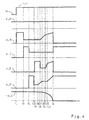
Der nachfolgenden Beschreibung liegt somit eine Getriebevorrichtung 1 zugrunde, welche bis auf das Schaltelement E grundsätzlich den gleichen konstruktiven Aufbau wie die Getriebevorrichtung 1 gemäß
Die in
Grundsätzlich ist das Schaltelement E zur Darstellung der zweiten Übersetzung "2", der sechsten Übersetzung "6" und der achten Übersetzung "8" in den Kraftfluss der Getriebevorrichtung 1 zuzuschalten und zur Darstellung der weiteren Übersetzungen "1 ", "3" bis "5", "7" und "9" für Vorwärtsfahrt in einen geöffneten Betriebszustand zu führen bzw. zu halten.Basically, the switching element E for displaying the second translation is "2", the sixth translation "6" and the eighth translation "8" in FIG to connect the power flow of the
Des Weiteren stellen die in
Zu einem Zeitpunkt T13 ist in der Getriebevorrichtung 1 die erste Übersetzungsstufe "1" oder die fünfte Übersetzungsstufe "5" eingelegt. Zu einem zeitlich darauf folgenden weiteren Zeitpunkt T14 liegt eine Anforderung für eine Zughochschaltung in Richtung der Ziel-Übersetzung "2" oder "6" vor, wobei zur Darstellung der zweiten Übersetzung "2" das reibschlüssige Schaltelement D abzuschalten und das formschlüssigen Schaltelement E zuzuschalten ist, während die beiden formschlüssigen Schaltelemente B und C in geschlossenem Betriebszustand gehalten werden. Wird durch die Zughochschaltung als Ziel-Übersetzung die sechste Übersetzungsstufe "6" angefordert, ist das reibschlüssige Schaltelement F abzuschalten und das formschlüssige Schaltelement E in den Kraftfluss zuzuschalten, während das formschlüssige Schaltelement C und das reibschlüssige Schaltelement A in geschlossenem Betriebszustand gehalten werden.At a time T13, the first gear stage "1" or the fifth gear stage "5" is engaged in the
Nachfolgend wird die weitere Variante des erfindungsgemäßen Verfahrens zunächst während der Durchführung der Zughochschaltung ausgehend von der ersten Übersetzungsstufe "1" in Richtung der angeforderten zweiten Übersetzung "2" näher beschrieben.In the following, the further variant of the method according to the invention will first be described in detail in the direction of the requested second translation "2" during the execution of the upshift starting from the first gear stage "1".
Zum Zeitpunkt T14, zu dem die Anforderung für die Zughochschaltung vorliegt, wird das reibschlüssige Schaltelement F, welches während der Darstellung der ersten Übersetzungsstufe "1" im Wesentlichen in seinem geöffneten Betriebszustand vorliegt, während eines sich bis zu einem Zeitpunkt T15 erstreckenden Schnellfüllpuls und während einer bis zu einem Zeitpunkt T16 andauernden sowie sich an den Schnellfüllpuls anschließenden Füllausgleichsphase in einen Betriebszustand überführt, von dem ausgehend ein Anheben des Betätigungsdruckes p_F einen Anstieg der Übertragungsfähigkeit bewirkt. Das zuzuschaltende formschlüssige Schaltelement E wird durch entsprechendes Anheben der Übertragungsfähigkeit des reibschlüssigen Schaltelementes F wenigstens annähernd in einen synchronen Betriebszustand überführt.At the time T14, at which the request for the pull upshift is present, the frictional switching element F, which during the presentation of the first gear stage "1" substantially in its open Operating state is present, during an up to a time T15 extending Schnellfüllpuls and during an ongoing until a time T16 and adjoining the Schnellfüllpuls Füllausgleichsphase into an operating state, starting from which starting raising the operating pressure p_F causes an increase in the transmission capacity. The zuzuschaltende positive switching element E is converted by appropriate lifting of the transmission capability of the frictional switching element F at least approximately in a synchronous operating state.
Hierfür wird der Betätigungsdruck p_F des reibschlüssigen Schaltelementes F nach dem Zeitpunkt T16 über eine bis zu einem weiteren Zeitpunkt T17 andauernde erste Druckrampe auf einen ersten Druckwert angehoben und während einer sich an die erste Druckrampe anschließenden zweiten Druckrampe, die eine geringere Steigung als die erste Druckrampe aufweist, bis zu einem Zeitpunkt T18 weiter erhöht.For this purpose, the actuation pressure p_F of the frictionally engaged switching element F is raised to a first pressure value after the time T16 via a first pressure ramp continuing until a further time T17 and during a second pressure ramp which adjoins the first pressure ramp and has a smaller pitch than the first pressure ramp , further increased until a time T18.
Gleichzeitig wird der Betätigungsdruck p_D des abzuschaltenden reibschlüssigen Schaltelementes D zum Zeitpunkt T15 sprungartig abgesenkt, anschließend bis zu einem Zeitpunkt T19 geregelt weiter reduziert und anschließend zum Zeitpunkt T19 im Wesentlichen vollständig auf Null geführt.At the same time, the actuation pressure p_D of the frictionally engaged switching element D to be disconnected is abruptly lowered at time T15, subsequently further reduced in a regulated manner up to a point in time T19, and then substantially completely zeroed out at time T19.
Das Absenken der Übertragungsfähigkeit des reibschlüssigen Schaltelementes D und die gleichzeitige Steigerung der Übertragungsfähigkeit des reibschlüssigen Schaltelementes F führt dazu, dass eine Getriebeeingangsdrehzahl n_mot der Getriebevorrichtung 1 zu einem Zeitpunkt T20, der im Wesentlichen dem Zeitpunkt T17 entspricht, ausgehend von einer zu der Synchrondrehzahl n_sync("1") der Ist-Übersetzung "1" äquivalenten Drehzahl in Richtung einer zu einer Synchrondrehzahl n_sync("2") der Ziel-Übersetzung "2" äquivalenten Drehzahl geführt wird, wobei die Getriebeeingangsdrehzahl n_mot im Wesentlichen der Synchrondrehzahl n_sync("2") vorliegend zum Zeitpunkt T18 entspricht.Lowering the transmissibility of the frictional engagement element D and simultaneously increasing the transmissibility of the frictional engagement element F results in a transmission input speed n_mot of the
Zu einem Zeitpunkt T21, der auf den Zeitpunkt T19 folgt und vor dem Zeitpunkt T18 liegt, wird der Betätigungsdruck p_E des zuzuschaltenden formschlüssigen Schaltelementes E auf einen ersten Druckwert angehoben, womit das formschlüssige Schaltelement E im Wesentlichen für die Zuschaltung vorbereitet wird. Anschließend wird der Betätigungsdruck p_E des formschlüssigen Schaltelementes E bis zum Zeitpunkt T18 im Wesentlichen auf dem zum Zeitpunkt T21 eingestellten Druckniveau gehalten. Zum Zeitpunkt T18, zu dem die Getriebeeingangsdrehzahl n_mot im Wesentlichen der Synchrondrehzahl n_sync("2") der Ziel-Übersetzung "2" entspricht, wird der Betätigungsdruck p_E des formschlüssigen Schaltelementes E auf das Schließdruckniveau angehoben und das formschlüssige Schaltelement E geschlossen.At a time T21, which follows the time T19 and before the time T18, the actuation pressure p_E of zuzuschaltenden positive switching element E is raised to a first pressure value, whereby the interlocking switching element E is prepared substantially for the connection. Subsequently, the actuation pressure p_E of the positive switching element E is maintained until the time T18 substantially at the pressure level set at time T21. At the time T18, at which the transmission input speed n_mot essentially corresponds to the synchronous speed n_sync ("2") of the target gear ratio "2", the actuation pressure p_E of the interlocking shift element E is raised to the closing pressure level and the interlocking shift element E is closed.
Das formschlüssige Schaltelement E befindet sich aufgrund der vorbeschriebenen Betätigung des reibschlüssigen Schaltelementes F zum Zeitpunkt T18 im Wesentlichen in seinem synchronen Betriebszustand und ist somit auf einfache Art und Weise aus seinem geöffneten Betriebszustand in seinen geschlossenen Betriebszustand überführbar. Der Betätigungsdruck p_F des reibschlüssigen Schaltelementes F wird nach dem Zeitpunkt T18 zunächst über eine bis zu einem Zeitpunkt T22 andauernde erste Druckrampe und eine sich daran anschließende zweite Druckrampe mit größerer Steigung im Wesentlichen auf Null abgesenkt, womit die angeforderte Zughochschaltung ausgehend von der ersten Übersetzungsstufe "1" in Richtung der zweiten Übersetzungsstufe "2" als beendet anzusehen ist.The positive switching element E is due to the above-described operation of the frictional engagement element F at time T18 substantially in its synchronous operating state and is thus in a simple manner from its open operating state into its closed operating state can be transferred. The actuation pressure p_F of the frictionally engaged shift element F is initially lowered substantially to zero over a time until a time T22 first pressure ramp and an adjoining second pressure ramp with a larger slope after the time T18, whereby the requested upshift starting from the first translation stage "1 "in the direction of the second translation stage" 2 "is considered to be completed.
Während der Durchführung der angeforderten Zughochschaltung stellt sich der in
Die Unstetigkeit im Verlauf der Fahrzeugbeschleunigung a_fzg resultiert aus der Tatsache, dass die Übertragungsfähigkeit des abzuschaltenden Schaltelementes D zum Zeitpunkt T15 bereits reduziert ist und die Übertragungsfähigkeit des zum Synchronisieren des zuzuschaltenden Schaltelementes E vorgesehenen reibschlüssigen Schaltelementes F das von einer Antriebsmaschine anliegende Drehmoment noch nicht im erforderlichen Umfang überträgt. Zum Zeitpunkt T23 ist die teilweise Lastübernahme im Bereich des Schaltelementes F vollzogen, womit die Fahrzeugbeschleunigung a_fzg bis zum Zeitpunkt T18 im Wesentlichen konstant bleibt. Zum Zeitpunkt T18, zu welchem das zuzuschaltende formschlüssige Schaltelement E geschlossen wird, sinkt die Fahrzeugbeschleunigung a_fzg auf das Niveau der Ziel-Übersetzung "2" ab und bleibt im Wesentlichen konstant.The discontinuity in the course of the vehicle acceleration a_fzg results from the fact that the transmissibility of the switching element D to be switched off is already reduced at time T15 and the transmission capability of the frictional switching element F provided for synchronizing the switching element E to be switched is not yet as required to the extent required by a drive machine transfers. At time T23, the partial load transfer in the region of the switching element F is completed, whereby the vehicle acceleration a_fzg remains substantially constant until time T18. At time T18, at which the positive-locking switching element E to be connected is closed, the vehicle acceleration a_fzg drops to the level of the target ratio "2" and remains substantially constant.
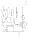
Die zu
Aufgrund der zu
Zughochschaltungen, während weichen zumindest ein formschlüssiges Schaltelement zuzuschalten ist, werden gemäß einer Variante des erfindungsgemäßen Verfahrens als Doppelhochschaltung bzw. als Mehrfachhochschaltung begonnen. Sobald die Getriebeeingangsdrehzahl jeweils die zur Synchrondrehzahl n_sync("2") bzw. n_sync("6") äquivalente Drehzahl erreicht, liegt das zu schließende formschlüssige Schaltelement E im Wesentlichen in synchronem Betriebszustand vor und ist dann einfach und zu einem definierten Zeitpunkt in seinen geschlossenen Betriebszustand überführbar. Die Übertragungsfähigkeit des die Synchronisierung des formschlüssigen Schaltelementes E bzw. die zugkraftunterbrechungsfreie Synchronisierung des formschlüssigen Schaltelementes E jeweils gewährleistenden reibschlüssigen Schaltelementes F oder D wird nach dem Zuschalten des formschlüssigen Schaltelementes E im Wesentlichen wieder auf Null oder auf einen niedrigen Wert abgesenkt.Zughochschaltungen, while soft at least one positive switching element is zuzuschalten be started according to a variant of the method according to the invention as a double upshift or as a multiple upshift. As soon as the transmission input rotational speed reaches the equivalent rotational speed n_sync ("2") or n_sync ("6"), the positive-locking switching element E to be closed lies substantially in synchronous operating state and is then in its closed state simply and at a defined time Operating state convertible. The transfer capability of the synchronization of the positive switching element E or the traction interruption-free synchronization of the positive switching element E respectively ensuring frictional switching element F or D is lowered after the connection of the positive switching element E substantially back to zero or to a low value.
Da im Bereich der für die Synchronisierung des formschlüssigen Schaltelementes E jeweils vorgesehenen Schaltelemente D und F unter Umständen hohe Reibleistungen auftreten können, sind diese beispielsweise über eine strategiefähige Kühlung und/oder eine entsprechende Getriebeschmierung versorgbar und/oder mit Hochleistungsreibbelägen ausführbar.Since high friction losses may occur in the region of the switching elements D and F respectively provided for the synchronization of the positive switching element E, these can be supplied, for example, via a cooling system capable of strategy and / or a corresponding gear lubrication and / or with high-performance friction linings.
Bei der Variante erfindungsgemäßen Vorgehensweise sind formschlüssige Schaltelemente jeweils nur zur Darstellung bis zum n-1ten Gang einer Getriebevorrichtung mit n-Gangstufen einsetzbar, da jeweils immer ein zur Darstellung des nächst höheren Ganges zuzuschaltendes reibschlüssiges Schaltelement für die Drehzahlangleichung bzw. die Synchronisierung des zuzuschaltenden formschlüssigen Schaltelementes herangezogen wird, um eine zugkraftunterbrechungsfreie Zughochschaltung durchführen zu können.In the variant according to the invention, interlocking shift elements can each be used only for presentation up to the n-1th gear of a transmission device with n-speed stages, as always one zuzuschaltendes for displaying the next higher gear frictional switching element for the speed matching or the synchronization of zuzuschaltenden positive switching element is used to perform a traction interruption-free upshift can.
Die erfindungsgemäße Vorgehensweise führt unter Umständen selbst bei einem Verzicht auf den höchstmöglichen Fahrgang bzw. dem Overdrive zu einer Reduzierung eines Kraftstoffverbrauches eines Fahrzeuges, wenn die Reduzierung des Kraftstoffverbrauches alleine aufgrund der Reduzierung der Schleppmomente im Bereich der Schaltelementes höher ist als während eines Betriebes im zusätzlichen Overdrive.The procedure according to the invention may even lead to a reduction of the fuel consumption of a vehicle even if the highest possible driving gear or the overdrive is dispensed with, if the reduction of fuel consumption is higher due to the reduction of the drag torque in the area of the shifting element than during operation in the additional overdrive ,
- 11
- Getriebevorrichtungtransmission device
- 22
- Antriebswelledrive shaft
- 33
- Abtriebswelleoutput shaft
- "1" bis "9""1" to "9"
- Übersetzung für VorwärtsfahrtTranslation for forward drive
- A bis FA to F
- Schaltelementswitching element
- a_fzga_fzg
- Fahrzeugbeschleunigungvehicle acceleration
- "N""N"
- NeutralbetriebszustandNeutral mode
- n_motn_mot
- GetriebeeingangsdrehzahlTransmission input speed
- n_syncn_sync
- SynchrondrehzahlSynchronous speed
- nd_Cnd_C
- Differenzdrehzahl des Schaltelementes CDifferential speed of the switching element C
- p_Ap_A
- Betätigungsdruckactuating pressure
- p_A1p_A1
- Druckniveaupressure level
- p_Bp_B
- Betätigungsdruckactuating pressure
- p_Cp_C
- Betätigungsdruckactuating pressure
- p_Dp_D
- Betätigungsdruckactuating pressure
- p_Ep_E
- Betätigungsdruckactuating pressure
- p_Fp_F
- Betätigungsdruckactuating pressure
- P1 bis P4P1 to P4
- Planetenradsatzplanetary gear
- "R""R"
- Übersetzung für RückwärtsfahrtTranslation for reverse
- T1 bis T23T1 to T23
- diskreter Zeitpunktdiscrete time
- tt
- ZeitTime
Claims (10)
- Method for operating a transmission device (1), having a plurality of frictionally locking shift elements (A, D, E, F) and at least one positively locking shift element (B, C) for bringing about different transmission ratios ("1" to "9", "R"), wherein in the event of a requested shift operation during which the positively locking shift element (C) is at least approximately synchronized and transferred into its closed operating state in at least an approximately synchronized operating state by raising the transmission capability of at least one frictionally locking shift element (A) which does not have to be connected into the force flux of the transmission device (1) either to bring about the current operating state of the transmission device (1) or to bring about the transmission ratio ("1") which is to be engaged, the positively locking shift element (C) is transferred from an opened operating state into a closed operating state, characterized in that subsequent to the transfer of the positively locking shift element (C) into its closed operating state a further frictionally locking shift element (D), which is to bring about the frictional engagement in the transmission device (1), is connected into the force flux of the transmission device (1) by correspondingly raising an activation pressure of the frictionally locking shift element (D), or is transferred into its closed operating state, wherein in order to form a transmission ratio in the transmission device (1) or in order to bring about a force flux in the transmission device (1) in each case three shift elements are to be placed or held in a closed operating state simultaneously.
- Method according to Claim 1, characterized in that the shift element (D) is already prepared for its connection by corresponding pressure regulation of its activation pressure even before a connection time (T6) of the positively locking shift element (C).
- Method according to Claim 1 or 2, characterized in that the transmission capability of at least one further frictionally locking shift element (E) which is not involved in the synchronization procedure of the positively locking shift element (C) either in bringing about the current operating state of the transmission device (1) or bringing about the transmission ratio ("1") to be engaged is raised before the synchronization of the positively locking shift element (C) which is brought about by raising the transmission capability of the frictionally locking shift element (A), and an output, which is operatively connected to a transmission output (3) of a vehicle which is embodied with the transmission device (1) is braked.
- Method according to Claim 3, characterized in that in the case of reverse travel of a vehicle which is embodied with the transmission device (1), with a vehicle speed which is higher than a predefined threshold value, in the case of a neutral operating state (N) of the transmission device, in which state the force flux in the transmission device (1) is essentially interrupted, and when a request to engage a transmission ratio ("1") for forward travel in the transmission device (1) is present, to bring about which transmission ratio ("1") the positively locking shift element (C) is to be transferred into a closed operating state, the transmission output (3) which is operatively connected to the output is braked by raising the transmission capability of the further frictionally locking shift element (E).
- Method according to one of Claims 1 to 4, characterized in that in the case of forward travel of a vehicle which is embodied with the transmission device (1), and in the case of a vehicle speed which is lower than a predefined threshold value, and in the case of a neutral operating state (N) of the transmission device (1) in which state the force flux in the transmission device is essentially interrupted, and when a request to engage a transmission ratio ("1") for forward travel in the transmission device (1) is present, to bring about which transmission ratio ("1") the positively locking shift element (C) has to be transferred into a closed operating state, the positively locking shift element (C) is at least approximately synchronized and subsequently closed by raising the transmission capability of a frictionally locking shift element (A), the transmission capability of which is essentially zero while the requested transmission ratio ("1") is being brought about, wherein subsequent to this a frictionally locking shift element (D) which brings about the force flux in the transmission device (1) is connected.
- Method according to Claim 5, characterized in that in the case of reverse travel with a vehicle speed which is less than the threshold value the positively locking shift element (C) is at least approximately synchronized and subsequently closed by raising the transmission capability of the frictionally locking shift element (A), and subsequently to this the frictionally locking shift element (D) which brings about the force flux in the transmission device (1) is in turn connected.
- Method according to one of Claims 1 to 6, characterized in that when a request for a traction upshift in order to bring about the requested target transmission ratio ("2" or "6") is present, the positively locking shift element (E) is to be connected, and before the connection is at least approximately synchronized by raising the transmission capability of at least one frictionally locking shift element (D or F) which does not have to be connected into the force flux of the transmission device (1) either to bring about the current operating state of the transmission device (1) or to bring about the requested operating state.
- Method according to Claim 7, characterized in that when a transmission input rotational speed (n_mot) which corresponds at least approximately to a synchronous rotational speed (n_sync("2") or n_sync ("6")) which is equivalent to the requested target transmission ratio ("2" or "6") is present, the transmission capability of the frictionally locking shift element (D or F) which is connected in order to bring about the actual transmission ratio ("1" or "5") is reduced, while the positively locking shift element (E) which is to be connected is transferred into a closed operating state.
- Method according to Claim 7 or 8, characterized in that when a request for the traction upshift starting from the actual transmission ratio ("1" or "5") in the direction of the target transmission ratio ("2" or "6") is present, the transmission capability of a frictionally locking shift element (D or F) which is connected into the force flux in order to bring about the actual transmission ratio ("1" or "5") is reduced if the frictionally locking shift element (F or D) which is provided for the synchronization of the positively locking shift element (E) which is to be connected is at least approximately prepared for the increasing of the transmission capability.
- Method according to one of Claims 7 to 9, characterized in that the transmission capability of the frictionally locking shift element (D or F) which is connected in order to bring about the actual transmission ratio ("1" or "5") is lowered at least approximately to zero if the transmission input rotational speed (n_mot) is regulated in the direction of the rotational speed (n_sync ("2") or n_sync ("6")), which is equivalent to the target transmission ratio ("2" or "6"), from the rotational speed (n_sync("1") or n_sync ("5")), which is equivalent to the actual transmission ratio ("1" or "5"), on the basis of the transmission capability of the frictionally locking shift element (F or D) which is provided for the synchronization of the positively locking shift element (E) which is to be connected.
Applications Claiming Priority (2)
| Application Number | Priority Date | Filing Date | Title |
|---|---|---|---|
| DE102009000253A DE102009000253A1 (en) | 2009-01-15 | 2009-01-15 | Method for operating a transmission device |
| PCT/EP2010/050341 WO2010081819A1 (en) | 2009-01-15 | 2010-01-13 | Method for the operation of a transmission device |
Publications (2)
| Publication Number | Publication Date |
|---|---|
| EP2376814A1 EP2376814A1 (en) | 2011-10-19 |
| EP2376814B1 true EP2376814B1 (en) | 2014-12-24 |
Family
ID=42029935
Family Applications (1)
| Application Number | Title | Priority Date | Filing Date |
|---|---|---|---|
| EP10700250.3A Active EP2376814B1 (en) | 2009-01-15 | 2010-01-13 | Method for the operation of a transmission device |
Country Status (6)
| Country | Link |
|---|---|
| US (1) | US8496562B2 (en) |
| EP (1) | EP2376814B1 (en) |
| KR (1) | KR101680917B1 (en) |
| CN (1) | CN102308125B (en) |
| DE (1) | DE102009000253A1 (en) |
| WO (1) | WO2010081819A1 (en) |
Families Citing this family (26)
| Publication number | Priority date | Publication date | Assignee | Title |
|---|---|---|---|---|
| DE102009056793A1 (en) * | 2009-12-03 | 2011-06-09 | Bayerische Motoren Werke Aktiengesellschaft | Method for switching automatic transmission of vehicle of reverse gear or neutral condition into forward gear or neutral condition into reverse gear, involves producing switching default from driver |
| DE102010042656B4 (en) * | 2010-10-20 | 2022-06-23 | Zf Friedrichshafen Ag | Powershift transmission |
| CA2833283A1 (en) * | 2011-05-02 | 2012-11-08 | Brock University | Processes and intermediates in the preparation of morphine analogs via n-demethylation of n-oxides using cyclodehydration reagents |
| DE102011076964A1 (en) * | 2011-06-06 | 2012-12-06 | Zf Friedrichshafen Ag | Method for switching transmission stage i.e. road gear, and/or reduction stage i.e. booster gear, in claw-switched transfer gear box in vehicle, involves asynchronizing switching element for assisting track adjustment of shifting claw |
| US8769819B2 (en) | 2011-10-14 | 2014-07-08 | Gm Global Technology Operations, Llc. | Methods of fabricating combination gear for stacked planetary gearset |
| DE102011087858B4 (en) | 2011-12-07 | 2024-01-18 | Zf Friedrichshafen Ag | Method for system pressure control for an automatic transmission comprising positive switching elements |
| DE102012211673A1 (en) * | 2012-07-05 | 2014-01-09 | Zf Friedrichshafen Ag | Method for operating an automatic transmission |
| DE102012216301A1 (en) * | 2012-09-13 | 2014-03-13 | Zf Friedrichshafen Ag | Method and control device for operating a transmission |
| DE102012220417A1 (en) | 2012-11-09 | 2014-05-15 | Zf Friedrichshafen Ag | Switching mechanism for automatic transmission for motor vehicle, has control device which is arranged between pressure source and operation device to join and to engage logic element half components with each other in defined position |
| DE102013202709A1 (en) * | 2013-02-20 | 2014-08-21 | Zf Friedrichshafen Ag | Method for operating a transmission device |
| DE102013202711A1 (en) * | 2013-02-20 | 2014-08-21 | Zf Friedrichshafen Ag | Method for operating a transmission device |
| DE102013202710A1 (en) * | 2013-02-20 | 2014-08-21 | Zf Friedrichshafen Ag | Method for operating a transmission device |
| DE102013204411A1 (en) * | 2013-03-14 | 2014-09-18 | Zf Friedrichshafen Ag | Method for carrying out push downshifts with participation of a form-fitting shift element in an automatic transmission comprising a lockup clutch |
| DE102013205177B4 (en) * | 2013-03-25 | 2019-01-17 | Bayerische Motoren Werke Aktiengesellschaft | Method for shifting a transmission |
| DE102013205564A1 (en) * | 2013-03-28 | 2014-10-02 | Zf Friedrichshafen Ag | Method for connecting a form-fitting switching element for realizing a gear in an automatic transmission, wherein at least one further Reibschaltelement is involved in the gear to be engaged |
| DE102013213239A1 (en) * | 2013-07-05 | 2015-01-22 | Zf Friedrichshafen Ag | Method and control device for operating a transmission |
| US9410621B2 (en) * | 2014-10-13 | 2016-08-09 | Zf Friedrichshafen Ag | Method for operating an automatic transmission in a limp mode |
| DE102014225455B4 (en) | 2014-12-10 | 2022-08-04 | Zf Friedrichshafen Ag | Method and control device for operating an automatic transmission |
| DE102014225453A1 (en) | 2014-12-10 | 2016-06-16 | Zf Friedrichshafen Ag | Method and control device for operating an automatic transmission |
| DE102015201922A1 (en) | 2015-02-04 | 2016-08-04 | Zf Friedrichshafen Ag | Method and control device for operating an automatic transmission |
| US9458929B2 (en) | 2015-03-05 | 2016-10-04 | Zf Friedrichshafen Ag | Method for operating an automatic transmission |
| DE102015005803A1 (en) * | 2015-05-06 | 2016-11-10 | Daimler Ag | Method for controlling a form-locking switching unit |
| DE102016200725B4 (en) * | 2016-01-20 | 2023-08-03 | Zf Friedrichshafen Ag | Method and control device for operating a transmission |
| DE102017204469A1 (en) * | 2017-03-17 | 2018-09-20 | Zf Friedrichshafen Ag | Method and control device for operating a transmission |
| DE102019209220A1 (en) * | 2019-06-26 | 2020-12-31 | Zf Friedrichshafen Ag | Method for operating a transmission |
| DE102019211405A1 (en) * | 2019-07-31 | 2021-02-04 | Zf Friedrichshafen Ag | Method and control device for operating a vehicle drive train |
Family Cites Families (13)
| Publication number | Priority date | Publication date | Assignee | Title |
|---|---|---|---|---|
| DE19714853A1 (en) * | 1997-04-10 | 1998-10-15 | Zahnradfabrik Friedrichshafen | Increasing the spontaneity of an automatic transmission |
| DE19814569C2 (en) * | 1998-04-01 | 2001-09-27 | Daimler Chrysler Ag | Gear change gear with a gear synchronizing gear |
| DE19830953A1 (en) * | 1998-07-10 | 2000-03-30 | Zahnradfabrik Friedrichshafen | Method and device for controlling a motor vehicle drive train |
| DE19939819C1 (en) * | 1999-08-21 | 2000-11-23 | Daimler Chrysler Ag | Transmission ratio switching method for automobile transmission uses controlled operation of clutches for 2 partial drive trains for selecting new gear ratio in disengaged drive train before re-engagement |
| DE10243278A1 (en) * | 2002-09-18 | 2004-03-25 | Volkswagen Ag | Device for synchronizing a double clutch transmission |
| DE102004014081A1 (en) * | 2004-03-23 | 2005-10-13 | Zf Friedrichshafen Ag | Planetary gear, in particular dual-clutch planetary gear |
| FR2883350B1 (en) | 2005-03-21 | 2008-11-07 | Peugeot Citroen Automobiles Sa | MOTOR VEHICLE GEARBOX AND METHOD OF CHANGING THE REPORTING FOR SUCH A GEARBOX. |
| DE102005032225B3 (en) * | 2005-07-09 | 2006-08-31 | Daimlerchrysler Ag | Estimating process for revs of transmission shaft involves estimating value dependent on switched-on duration of synchronizing element |
| DE102006006637B4 (en) * | 2006-02-14 | 2015-02-19 | Zf Friedrichshafen Ag | Multi-speed transmission |
| DE102006026602B4 (en) * | 2006-06-08 | 2020-07-09 | Zf Friedrichshafen Ag | Method of operating a drive train |
| DE102007023957A1 (en) * | 2007-05-23 | 2008-11-27 | Zf Friedrichshafen Ag | Method for controlling an automated powershift transmission |
| US7896770B2 (en) * | 2007-08-01 | 2011-03-01 | GM Global Technology Operations LLC | Multi-speed transmission |
| DE102008000429A1 (en) | 2008-02-28 | 2009-09-03 | Zf Friedrichshafen Ag | Multi-speed transmission |
-
2009
- 2009-01-15 DE DE102009000253A patent/DE102009000253A1/en not_active Withdrawn
-
2010
- 2010-01-13 KR KR1020117016365A patent/KR101680917B1/en active IP Right Grant
- 2010-01-13 EP EP10700250.3A patent/EP2376814B1/en active Active
- 2010-01-13 WO PCT/EP2010/050341 patent/WO2010081819A1/en active Application Filing
- 2010-01-13 US US13/140,032 patent/US8496562B2/en active Active
- 2010-01-13 CN CN201080004749.3A patent/CN102308125B/en active Active
Also Published As
| Publication number | Publication date |
|---|---|
| EP2376814A1 (en) | 2011-10-19 |
| KR20110112342A (en) | 2011-10-12 |
| KR101680917B1 (en) | 2016-11-29 |
| DE102009000253A1 (en) | 2010-07-22 |
| WO2010081819A1 (en) | 2010-07-22 |
| CN102308125B (en) | 2014-04-30 |
| US20110263382A1 (en) | 2011-10-27 |
| CN102308125A (en) | 2012-01-04 |
| US8496562B2 (en) | 2013-07-30 |
Similar Documents
| Publication | Publication Date | Title |
|---|---|---|
| EP2376814B1 (en) | Method for the operation of a transmission device | |
| EP2524156B1 (en) | Method for operating a transmission device having a plurality of friction-fit shift elements and at least one form-fit shift element | |
| EP0478945B1 (en) | Automatic gear change method of a multiple-path-gear-transmission using servo pressure means | |
| EP2652363B1 (en) | Method for the operation of a transmission device in a vehicle drive train | |
| EP2417378B1 (en) | Method for operating a vehicle drive train | |
| DE102009002203A1 (en) | Method for operating a transmission device with a plurality of friction and form-locking switching elements | |
| WO2011015466A1 (en) | Method for operating a transmission device of a vehicle drivetrain | |
| EP2457794A2 (en) | Method for operating a drive train | |
| EP2652365B1 (en) | Method for the operation of a transmission device in a vehicle drive train, comprising at least one form-fitting shifting element and multiple frictionally engaged shifting elements | |
| DE19908602A1 (en) | Automated drive train for a motor vehicle and method for controlling a drive train | |
| EP3393874B1 (en) | Method for operating a vehicle with a vehicle powertrain and a vehicle brake | |
| EP2524157B1 (en) | Method for operating a vehicle drive train having an internal combustion engine | |
| EP2870384B1 (en) | Method for operating an automatic transmission | |
| DE102013202709A1 (en) | Method for operating a transmission device | |
| DE102013202710A1 (en) | Method for operating a transmission device | |
| DE102015211367A1 (en) | Automatic transmission of a vehicle with a central synchronization device and method for operating an automatic transmission | |
| EP1002971B1 (en) | Vehicle drive train and method for controlling the shifting of the drive train | |
| DE102010063024A1 (en) | Method for operating transmission device vehicle drive train for wheel assembly, involves determining actual closing timing in function of course of operating state quantity of transmission apparatus | |
| DE19845604C5 (en) | Multi-step transmission and method for designing a gear of a stepped transmission | |
| DE102013202711A1 (en) | Method for operating a transmission device | |
| WO2022058122A1 (en) | Motor vehicle comprising at least two drive motors and comprising an automatic gearbox having a fixed gear ratio and a power-split gear ratio | |
| EP3878672A1 (en) | Method for operating a hybrid drive assembly with transmission and electric machine | |
| DE102014219099A1 (en) | Method for switching control of an automated manual transmission in an electric motor driven vehicle | |
| DE10321281A1 (en) | Automatic gearbox gear change method for either changing up or down in which torque transfer to the new gear change element commences before synchronized rotation speeds are achieved | |
| DE102010063026A1 (en) | Method for operating transmission device of vehicle drivetrain, involves varying course gradient of differential speed between current transmission input speed and synchronous input speed by applying rotation torque to transmission device |
Legal Events
| Date | Code | Title | Description |
|---|---|---|---|
| PUAI | Public reference made under article 153(3) epc to a published international application that has entered the european phase |
Free format text: ORIGINAL CODE: 0009012 |
|
| 17P | Request for examination filed |
Effective date: 20110601 |
|
| AK | Designated contracting states |
Kind code of ref document: A1 Designated state(s): AT BE BG CH CY CZ DE DK EE ES FI FR GB GR HR HU IE IS IT LI LT LU LV MC MK MT NL NO PL PT RO SE SI SK SM TR |
|
| DAX | Request for extension of the european patent (deleted) | ||
| GRAP | Despatch of communication of intention to grant a patent |
Free format text: ORIGINAL CODE: EPIDOSNIGR1 |
|
| INTG | Intention to grant announced |
Effective date: 20140807 |
|
| GRAS | Grant fee paid |
Free format text: ORIGINAL CODE: EPIDOSNIGR3 |
|
| GRAA | (expected) grant |
Free format text: ORIGINAL CODE: 0009210 |
|
| AK | Designated contracting states |
Kind code of ref document: B1 Designated state(s): AT BE BG CH CY CZ DE DK EE ES FI FR GB GR HR HU IE IS IT LI LT LU LV MC MK MT NL NO PL PT RO SE SI SK SM TR |
|
| REG | Reference to a national code |
Ref country code: GB Ref legal event code: FG4D Free format text: NOT ENGLISH |
|
| REG | Reference to a national code |
Ref country code: CH Ref legal event code: EP |
|
| REG | Reference to a national code |
Ref country code: IE Ref legal event code: FG4D Free format text: LANGUAGE OF EP DOCUMENT: GERMAN |
|
| REG | Reference to a national code |
Ref country code: AT Ref legal event code: REF Ref document number: 703331 Country of ref document: AT Kind code of ref document: T Effective date: 20150115 |
|
| REG | Reference to a national code |
Ref country code: DE Ref legal event code: R096 Ref document number: 502010008563 Country of ref document: DE Effective date: 20150219 |
|
| REG | Reference to a national code |
Ref country code: NL Ref legal event code: VDEP Effective date: 20141224 |
|
| PG25 | Lapsed in a contracting state [announced via postgrant information from national office to epo] |
Ref country code: FI Free format text: LAPSE BECAUSE OF FAILURE TO SUBMIT A TRANSLATION OF THE DESCRIPTION OR TO PAY THE FEE WITHIN THE PRESCRIBED TIME-LIMIT Effective date: 20141224 Ref country code: NO Free format text: LAPSE BECAUSE OF FAILURE TO SUBMIT A TRANSLATION OF THE DESCRIPTION OR TO PAY THE FEE WITHIN THE PRESCRIBED TIME-LIMIT Effective date: 20150324 Ref country code: LT Free format text: LAPSE BECAUSE OF FAILURE TO SUBMIT A TRANSLATION OF THE DESCRIPTION OR TO PAY THE FEE WITHIN THE PRESCRIBED TIME-LIMIT Effective date: 20141224 |
|
| REG | Reference to a national code |
Ref country code: LT Ref legal event code: MG4D |
|
| PG25 | Lapsed in a contracting state [announced via postgrant information from national office to epo] |
Ref country code: LV Free format text: LAPSE BECAUSE OF FAILURE TO SUBMIT A TRANSLATION OF THE DESCRIPTION OR TO PAY THE FEE WITHIN THE PRESCRIBED TIME-LIMIT Effective date: 20141224 Ref country code: HR Free format text: LAPSE BECAUSE OF FAILURE TO SUBMIT A TRANSLATION OF THE DESCRIPTION OR TO PAY THE FEE WITHIN THE PRESCRIBED TIME-LIMIT Effective date: 20141224 Ref country code: GR Free format text: LAPSE BECAUSE OF FAILURE TO SUBMIT A TRANSLATION OF THE DESCRIPTION OR TO PAY THE FEE WITHIN THE PRESCRIBED TIME-LIMIT Effective date: 20150325 Ref country code: SE Free format text: LAPSE BECAUSE OF FAILURE TO SUBMIT A TRANSLATION OF THE DESCRIPTION OR TO PAY THE FEE WITHIN THE PRESCRIBED TIME-LIMIT Effective date: 20141224 |
|
| PG25 | Lapsed in a contracting state [announced via postgrant information from national office to epo] |
Ref country code: NL Free format text: LAPSE BECAUSE OF FAILURE TO SUBMIT A TRANSLATION OF THE DESCRIPTION OR TO PAY THE FEE WITHIN THE PRESCRIBED TIME-LIMIT Effective date: 20141224 |
|
| PG25 | Lapsed in a contracting state [announced via postgrant information from national office to epo] |
Ref country code: RO Free format text: LAPSE BECAUSE OF FAILURE TO SUBMIT A TRANSLATION OF THE DESCRIPTION OR TO PAY THE FEE WITHIN THE PRESCRIBED TIME-LIMIT Effective date: 20141224 Ref country code: CZ Free format text: LAPSE BECAUSE OF FAILURE TO SUBMIT A TRANSLATION OF THE DESCRIPTION OR TO PAY THE FEE WITHIN THE PRESCRIBED TIME-LIMIT Effective date: 20141224 Ref country code: EE Free format text: LAPSE BECAUSE OF FAILURE TO SUBMIT A TRANSLATION OF THE DESCRIPTION OR TO PAY THE FEE WITHIN THE PRESCRIBED TIME-LIMIT Effective date: 20141224 Ref country code: ES Free format text: LAPSE BECAUSE OF FAILURE TO SUBMIT A TRANSLATION OF THE DESCRIPTION OR TO PAY THE FEE WITHIN THE PRESCRIBED TIME-LIMIT Effective date: 20141224 Ref country code: SK Free format text: LAPSE BECAUSE OF FAILURE TO SUBMIT A TRANSLATION OF THE DESCRIPTION OR TO PAY THE FEE WITHIN THE PRESCRIBED TIME-LIMIT Effective date: 20141224 |
|
| REG | Reference to a national code |
Ref country code: CH Ref legal event code: PL |
|
| PG25 | Lapsed in a contracting state [announced via postgrant information from national office to epo] |
Ref country code: PL Free format text: LAPSE BECAUSE OF FAILURE TO SUBMIT A TRANSLATION OF THE DESCRIPTION OR TO PAY THE FEE WITHIN THE PRESCRIBED TIME-LIMIT Effective date: 20141224 Ref country code: IS Free format text: LAPSE BECAUSE OF FAILURE TO SUBMIT A TRANSLATION OF THE DESCRIPTION OR TO PAY THE FEE WITHIN THE PRESCRIBED TIME-LIMIT Effective date: 20150424 Ref country code: LU Free format text: LAPSE BECAUSE OF FAILURE TO SUBMIT A TRANSLATION OF THE DESCRIPTION OR TO PAY THE FEE WITHIN THE PRESCRIBED TIME-LIMIT Effective date: 20150113 |
|
| REG | Reference to a national code |
Ref country code: DE Ref legal event code: R097 Ref document number: 502010008563 Country of ref document: DE |
|
| PG25 | Lapsed in a contracting state [announced via postgrant information from national office to epo] |
Ref country code: MC Free format text: LAPSE BECAUSE OF FAILURE TO SUBMIT A TRANSLATION OF THE DESCRIPTION OR TO PAY THE FEE WITHIN THE PRESCRIBED TIME-LIMIT Effective date: 20141224 |
|
| PG25 | Lapsed in a contracting state [announced via postgrant information from national office to epo] |
Ref country code: DK Free format text: LAPSE BECAUSE OF FAILURE TO SUBMIT A TRANSLATION OF THE DESCRIPTION OR TO PAY THE FEE WITHIN THE PRESCRIBED TIME-LIMIT Effective date: 20141224 Ref country code: CH Free format text: LAPSE BECAUSE OF NON-PAYMENT OF DUE FEES Effective date: 20150131 Ref country code: LI Free format text: LAPSE BECAUSE OF NON-PAYMENT OF DUE FEES Effective date: 20150131 |
|
| PLBE | No opposition filed within time limit |
Free format text: ORIGINAL CODE: 0009261 |
|
| REG | Reference to a national code |
Ref country code: IE Ref legal event code: MM4A |
|
| STAA | Information on the status of an ep patent application or granted ep patent |
Free format text: STATUS: NO OPPOSITION FILED WITHIN TIME LIMIT |
|
| 26N | No opposition filed |
Effective date: 20150925 |
|
| REG | Reference to a national code |
Ref country code: FR Ref legal event code: PLFP Year of fee payment: 7 |
|
| PG25 | Lapsed in a contracting state [announced via postgrant information from national office to epo] |
Ref country code: IT Free format text: LAPSE BECAUSE OF FAILURE TO SUBMIT A TRANSLATION OF THE DESCRIPTION OR TO PAY THE FEE WITHIN THE PRESCRIBED TIME-LIMIT Effective date: 20141224 |
|
| PG25 | Lapsed in a contracting state [announced via postgrant information from national office to epo] |
Ref country code: IE Free format text: LAPSE BECAUSE OF NON-PAYMENT OF DUE FEES Effective date: 20150113 |
|
| PG25 | Lapsed in a contracting state [announced via postgrant information from national office to epo] |
Ref country code: SI Free format text: LAPSE BECAUSE OF FAILURE TO SUBMIT A TRANSLATION OF THE DESCRIPTION OR TO PAY THE FEE WITHIN THE PRESCRIBED TIME-LIMIT Effective date: 20141224 |
|
| REG | Reference to a national code |
Ref country code: AT Ref legal event code: MM01 Ref document number: 703331 Country of ref document: AT Kind code of ref document: T Effective date: 20150113 |
|
| PG25 | Lapsed in a contracting state [announced via postgrant information from national office to epo] |
Ref country code: AT Free format text: LAPSE BECAUSE OF NON-PAYMENT OF DUE FEES Effective date: 20150113 |
|
| REG | Reference to a national code |
Ref country code: FR Ref legal event code: PLFP Year of fee payment: 8 |
|
| PG25 | Lapsed in a contracting state [announced via postgrant information from national office to epo] |
Ref country code: MT Free format text: LAPSE BECAUSE OF FAILURE TO SUBMIT A TRANSLATION OF THE DESCRIPTION OR TO PAY THE FEE WITHIN THE PRESCRIBED TIME-LIMIT Effective date: 20141224 |
|
| PG25 | Lapsed in a contracting state [announced via postgrant information from national office to epo] |
Ref country code: SM Free format text: LAPSE BECAUSE OF FAILURE TO SUBMIT A TRANSLATION OF THE DESCRIPTION OR TO PAY THE FEE WITHIN THE PRESCRIBED TIME-LIMIT Effective date: 20141224 Ref country code: BG Free format text: LAPSE BECAUSE OF FAILURE TO SUBMIT A TRANSLATION OF THE DESCRIPTION OR TO PAY THE FEE WITHIN THE PRESCRIBED TIME-LIMIT Effective date: 20141224 Ref country code: HU Free format text: LAPSE BECAUSE OF FAILURE TO SUBMIT A TRANSLATION OF THE DESCRIPTION OR TO PAY THE FEE WITHIN THE PRESCRIBED TIME-LIMIT; INVALID AB INITIO Effective date: 20100113 |
|
| PG25 | Lapsed in a contracting state [announced via postgrant information from national office to epo] |
Ref country code: CY Free format text: LAPSE BECAUSE OF FAILURE TO SUBMIT A TRANSLATION OF THE DESCRIPTION OR TO PAY THE FEE WITHIN THE PRESCRIBED TIME-LIMIT Effective date: 20141224 |
|
| PG25 | Lapsed in a contracting state [announced via postgrant information from national office to epo] |
Ref country code: PT Free format text: LAPSE BECAUSE OF FAILURE TO SUBMIT A TRANSLATION OF THE DESCRIPTION OR TO PAY THE FEE WITHIN THE PRESCRIBED TIME-LIMIT Effective date: 20150424 Ref country code: BE Free format text: LAPSE BECAUSE OF NON-PAYMENT OF DUE FEES Effective date: 20150131 |
|
| PG25 | Lapsed in a contracting state [announced via postgrant information from national office to epo] |
Ref country code: TR Free format text: LAPSE BECAUSE OF FAILURE TO SUBMIT A TRANSLATION OF THE DESCRIPTION OR TO PAY THE FEE WITHIN THE PRESCRIBED TIME-LIMIT Effective date: 20141224 |
|
| REG | Reference to a national code |
Ref country code: FR Ref legal event code: PLFP Year of fee payment: 9 |
|
| PG25 | Lapsed in a contracting state [announced via postgrant information from national office to epo] |
Ref country code: MK Free format text: LAPSE BECAUSE OF FAILURE TO SUBMIT A TRANSLATION OF THE DESCRIPTION OR TO PAY THE FEE WITHIN THE PRESCRIBED TIME-LIMIT Effective date: 20141224 |
|
| PGFP | Annual fee paid to national office [announced via postgrant information from national office to epo] |
Ref country code: FR Payment date: 20191216 Year of fee payment: 11 |
|
| PGFP | Annual fee paid to national office [announced via postgrant information from national office to epo] |
Ref country code: GB Payment date: 20200102 Year of fee payment: 11 |
|
| GBPC | Gb: european patent ceased through non-payment of renewal fee |
Effective date: 20210113 |
|
| PG25 | Lapsed in a contracting state [announced via postgrant information from national office to epo] |
Ref country code: FR Free format text: LAPSE BECAUSE OF NON-PAYMENT OF DUE FEES Effective date: 20210131 |
|
| PG25 | Lapsed in a contracting state [announced via postgrant information from national office to epo] |
Ref country code: GB Free format text: LAPSE BECAUSE OF NON-PAYMENT OF DUE FEES Effective date: 20210113 |
|
| PGFP | Annual fee paid to national office [announced via postgrant information from national office to epo] |
Ref country code: DE Payment date: 20221123 Year of fee payment: 14 |
|
| P01 | Opt-out of the competence of the unified patent court (upc) registered |
Effective date: 20230528 |