EP2376750B1 - Scr closed loop control system - Google Patents
Scr closed loop control system Download PDFInfo
- Publication number
- EP2376750B1 EP2376750B1 EP08878782.5A EP08878782A EP2376750B1 EP 2376750 B1 EP2376750 B1 EP 2376750B1 EP 08878782 A EP08878782 A EP 08878782A EP 2376750 B1 EP2376750 B1 EP 2376750B1
- Authority
- EP
- European Patent Office
- Prior art keywords
- nox
- scr
- catalyst
- urea
- sensor
- Prior art date
- Legal status (The legal status is an assumption and is not a legal conclusion. Google has not performed a legal analysis and makes no representation as to the accuracy of the status listed.)
- Active
Links
- 239000003054 catalyst Substances 0.000 claims description 72
- XSQUKJJJFZCRTK-UHFFFAOYSA-N Urea Chemical compound NC(N)=O XSQUKJJJFZCRTK-UHFFFAOYSA-N 0.000 claims description 40
- 239000004202 carbamide Substances 0.000 claims description 40
- QGZKDVFQNNGYKY-UHFFFAOYSA-N Ammonia Chemical compound N QGZKDVFQNNGYKY-UHFFFAOYSA-N 0.000 claims description 37
- 238000006243 chemical reaction Methods 0.000 claims description 23
- 238000011144 upstream manufacturing Methods 0.000 claims description 16
- 229910021529 ammonia Inorganic materials 0.000 claims description 15
- 238000000034 method Methods 0.000 claims description 14
- 230000002829 reductive effect Effects 0.000 claims description 10
- 230000001419 dependent effect Effects 0.000 claims description 9
- 238000002347 injection Methods 0.000 claims description 8
- 239000007924 injection Substances 0.000 claims description 8
- 231100000572 poisoning Toxicity 0.000 claims description 4
- 230000000607 poisoning effect Effects 0.000 claims description 4
- 230000006866 deterioration Effects 0.000 claims description 3
- 230000032683 aging Effects 0.000 claims description 2
- MWUXSHHQAYIFBG-UHFFFAOYSA-N nitrogen oxide Inorganic materials O=[N] MWUXSHHQAYIFBG-UHFFFAOYSA-N 0.000 description 63
- 239000007789 gas Substances 0.000 description 35
- 239000004071 soot Substances 0.000 description 32
- 239000005864 Sulphur Substances 0.000 description 29
- NINIDFKCEFEMDL-UHFFFAOYSA-N Sulfur Chemical compound [S] NINIDFKCEFEMDL-UHFFFAOYSA-N 0.000 description 27
- 230000003647 oxidation Effects 0.000 description 21
- 238000007254 oxidation reaction Methods 0.000 description 21
- 239000000446 fuel Substances 0.000 description 14
- 230000009467 reduction Effects 0.000 description 12
- 238000006722 reduction reaction Methods 0.000 description 12
- 235000019391 nitrogen oxide Nutrition 0.000 description 11
- GQPLMRYTRLFLPF-UHFFFAOYSA-N Nitrous Oxide Chemical compound [O-][N+]#N GQPLMRYTRLFLPF-UHFFFAOYSA-N 0.000 description 10
- 230000015572 biosynthetic process Effects 0.000 description 9
- 230000008901 benefit Effects 0.000 description 7
- 230000003197 catalytic effect Effects 0.000 description 7
- IJGRMHOSHXDMSA-UHFFFAOYSA-N Atomic nitrogen Chemical compound N#N IJGRMHOSHXDMSA-UHFFFAOYSA-N 0.000 description 6
- 239000011248 coating agent Substances 0.000 description 6
- 238000000576 coating method Methods 0.000 description 6
- 229910000069 nitrogen hydride Inorganic materials 0.000 description 5
- 239000001272 nitrous oxide Substances 0.000 description 5
- 230000015556 catabolic process Effects 0.000 description 4
- 238000006731 degradation reaction Methods 0.000 description 4
- 230000001590 oxidative effect Effects 0.000 description 4
- 239000002956 ash Substances 0.000 description 3
- QVGXLLKOCUKJST-UHFFFAOYSA-N atomic oxygen Chemical compound [O] QVGXLLKOCUKJST-UHFFFAOYSA-N 0.000 description 3
- 239000003638 chemical reducing agent Substances 0.000 description 3
- 239000001301 oxygen Substances 0.000 description 3
- 229910052760 oxygen Inorganic materials 0.000 description 3
- 230000008929 regeneration Effects 0.000 description 3
- 238000011069 regeneration method Methods 0.000 description 3
- 235000002918 Fraxinus excelsior Nutrition 0.000 description 2
- 229910021536 Zeolite Inorganic materials 0.000 description 2
- 238000004364 calculation method Methods 0.000 description 2
- 238000010531 catalytic reduction reaction Methods 0.000 description 2
- 238000002485 combustion reaction Methods 0.000 description 2
- 238000003745 diagnosis Methods 0.000 description 2
- 229910001873 dinitrogen Inorganic materials 0.000 description 2
- HNPSIPDUKPIQMN-UHFFFAOYSA-N dioxosilane;oxo(oxoalumanyloxy)alumane Chemical compound O=[Si]=O.O=[Al]O[Al]=O HNPSIPDUKPIQMN-UHFFFAOYSA-N 0.000 description 2
- 239000000463 material Substances 0.000 description 2
- 229910052757 nitrogen Inorganic materials 0.000 description 2
- 230000001105 regulatory effect Effects 0.000 description 2
- 239000010457 zeolite Substances 0.000 description 2
- OKTJSMMVPCPJKN-UHFFFAOYSA-N Carbon Chemical compound [C] OKTJSMMVPCPJKN-UHFFFAOYSA-N 0.000 description 1
- 230000002159 abnormal effect Effects 0.000 description 1
- 238000009825 accumulation Methods 0.000 description 1
- 230000003213 activating effect Effects 0.000 description 1
- 230000004913 activation Effects 0.000 description 1
- 239000011149 active material Substances 0.000 description 1
- XKMRRTOUMJRJIA-UHFFFAOYSA-N ammonia nh3 Chemical compound N.N XKMRRTOUMJRJIA-UHFFFAOYSA-N 0.000 description 1
- 238000013459 approach Methods 0.000 description 1
- 238000013528 artificial neural network Methods 0.000 description 1
- 230000009286 beneficial effect Effects 0.000 description 1
- 229910052799 carbon Inorganic materials 0.000 description 1
- 230000002860 competitive effect Effects 0.000 description 1
- 239000000470 constituent Substances 0.000 description 1
- 230000001276 controlling effect Effects 0.000 description 1
- 238000012937 correction Methods 0.000 description 1
- 238000000354 decomposition reaction Methods 0.000 description 1
- 230000003247 decreasing effect Effects 0.000 description 1
- 238000003795 desorption Methods 0.000 description 1
- 238000001514 detection method Methods 0.000 description 1
- 238000002405 diagnostic procedure Methods 0.000 description 1
- 239000002283 diesel fuel Substances 0.000 description 1
- 230000000694 effects Effects 0.000 description 1
- 238000009472 formulation Methods 0.000 description 1
- 239000005431 greenhouse gas Substances 0.000 description 1
- JEGUKCSWCFPDGT-UHFFFAOYSA-N h2o hydrate Chemical compound O.O JEGUKCSWCFPDGT-UHFFFAOYSA-N 0.000 description 1
- 238000010438 heat treatment Methods 0.000 description 1
- 230000000670 limiting effect Effects 0.000 description 1
- 239000000314 lubricant Substances 0.000 description 1
- 238000005461 lubrication Methods 0.000 description 1
- 238000005259 measurement Methods 0.000 description 1
- 229910044991 metal oxide Inorganic materials 0.000 description 1
- 150000004706 metal oxides Chemical class 0.000 description 1
- 230000005012 migration Effects 0.000 description 1
- 238000013508 migration Methods 0.000 description 1
- 239000000203 mixture Substances 0.000 description 1
- 229910000510 noble metal Inorganic materials 0.000 description 1
- 125000004430 oxygen atom Chemical group O* 0.000 description 1
- 230000036961 partial effect Effects 0.000 description 1
- 239000013618 particulate matter Substances 0.000 description 1
- 239000002574 poison Substances 0.000 description 1
- 231100000614 poison Toxicity 0.000 description 1
- 238000004064 recycling Methods 0.000 description 1
- 230000004044 response Effects 0.000 description 1
- 230000002441 reversible effect Effects 0.000 description 1
- 238000001179 sorption measurement Methods 0.000 description 1
- 230000001629 suppression Effects 0.000 description 1
- 229910052720 vanadium Inorganic materials 0.000 description 1
- LEONUFNNVUYDNQ-UHFFFAOYSA-N vanadium atom Chemical compound [V] LEONUFNNVUYDNQ-UHFFFAOYSA-N 0.000 description 1
Images
Classifications
-
- F—MECHANICAL ENGINEERING; LIGHTING; HEATING; WEAPONS; BLASTING
- F01—MACHINES OR ENGINES IN GENERAL; ENGINE PLANTS IN GENERAL; STEAM ENGINES
- F01N—GAS-FLOW SILENCERS OR EXHAUST APPARATUS FOR MACHINES OR ENGINES IN GENERAL; GAS-FLOW SILENCERS OR EXHAUST APPARATUS FOR INTERNAL COMBUSTION ENGINES
- F01N3/00—Exhaust or silencing apparatus having means for purifying, rendering innocuous, or otherwise treating exhaust
- F01N3/08—Exhaust or silencing apparatus having means for purifying, rendering innocuous, or otherwise treating exhaust for rendering innocuous
- F01N3/10—Exhaust or silencing apparatus having means for purifying, rendering innocuous, or otherwise treating exhaust for rendering innocuous by thermal or catalytic conversion of noxious components of exhaust
- F01N3/18—Exhaust or silencing apparatus having means for purifying, rendering innocuous, or otherwise treating exhaust for rendering innocuous by thermal or catalytic conversion of noxious components of exhaust characterised by methods of operation; Control
- F01N3/20—Exhaust or silencing apparatus having means for purifying, rendering innocuous, or otherwise treating exhaust for rendering innocuous by thermal or catalytic conversion of noxious components of exhaust characterised by methods of operation; Control specially adapted for catalytic conversion ; Methods of operation or control of catalytic converters
- F01N3/2066—Selective catalytic reduction [SCR]
- F01N3/208—Control of selective catalytic reduction [SCR], e.g. dosing of reducing agent
-
- F—MECHANICAL ENGINEERING; LIGHTING; HEATING; WEAPONS; BLASTING
- F01—MACHINES OR ENGINES IN GENERAL; ENGINE PLANTS IN GENERAL; STEAM ENGINES
- F01N—GAS-FLOW SILENCERS OR EXHAUST APPARATUS FOR MACHINES OR ENGINES IN GENERAL; GAS-FLOW SILENCERS OR EXHAUST APPARATUS FOR INTERNAL COMBUSTION ENGINES
- F01N11/00—Monitoring or diagnostic devices for exhaust-gas treatment apparatus, e.g. for catalytic activity
-
- F—MECHANICAL ENGINEERING; LIGHTING; HEATING; WEAPONS; BLASTING
- F01—MACHINES OR ENGINES IN GENERAL; ENGINE PLANTS IN GENERAL; STEAM ENGINES
- F01N—GAS-FLOW SILENCERS OR EXHAUST APPARATUS FOR MACHINES OR ENGINES IN GENERAL; GAS-FLOW SILENCERS OR EXHAUST APPARATUS FOR INTERNAL COMBUSTION ENGINES
- F01N13/00—Exhaust or silencing apparatus characterised by constructional features ; Exhaust or silencing apparatus, or parts thereof, having pertinent characteristics not provided for in, or of interest apart from, groups F01N1/00 - F01N5/00, F01N9/00, F01N11/00
- F01N13/009—Exhaust or silencing apparatus characterised by constructional features ; Exhaust or silencing apparatus, or parts thereof, having pertinent characteristics not provided for in, or of interest apart from, groups F01N1/00 - F01N5/00, F01N9/00, F01N11/00 having two or more separate purifying devices arranged in series
-
- F—MECHANICAL ENGINEERING; LIGHTING; HEATING; WEAPONS; BLASTING
- F01—MACHINES OR ENGINES IN GENERAL; ENGINE PLANTS IN GENERAL; STEAM ENGINES
- F01N—GAS-FLOW SILENCERS OR EXHAUST APPARATUS FOR MACHINES OR ENGINES IN GENERAL; GAS-FLOW SILENCERS OR EXHAUST APPARATUS FOR INTERNAL COMBUSTION ENGINES
- F01N3/00—Exhaust or silencing apparatus having means for purifying, rendering innocuous, or otherwise treating exhaust
- F01N3/08—Exhaust or silencing apparatus having means for purifying, rendering innocuous, or otherwise treating exhaust for rendering innocuous
- F01N3/10—Exhaust or silencing apparatus having means for purifying, rendering innocuous, or otherwise treating exhaust for rendering innocuous by thermal or catalytic conversion of noxious components of exhaust
- F01N3/103—Oxidation catalysts for HC and CO only
-
- F—MECHANICAL ENGINEERING; LIGHTING; HEATING; WEAPONS; BLASTING
- F01—MACHINES OR ENGINES IN GENERAL; ENGINE PLANTS IN GENERAL; STEAM ENGINES
- F01N—GAS-FLOW SILENCERS OR EXHAUST APPARATUS FOR MACHINES OR ENGINES IN GENERAL; GAS-FLOW SILENCERS OR EXHAUST APPARATUS FOR INTERNAL COMBUSTION ENGINES
- F01N3/00—Exhaust or silencing apparatus having means for purifying, rendering innocuous, or otherwise treating exhaust
- F01N3/08—Exhaust or silencing apparatus having means for purifying, rendering innocuous, or otherwise treating exhaust for rendering innocuous
- F01N3/10—Exhaust or silencing apparatus having means for purifying, rendering innocuous, or otherwise treating exhaust for rendering innocuous by thermal or catalytic conversion of noxious components of exhaust
- F01N3/105—General auxiliary catalysts, e.g. upstream or downstream of the main catalyst
- F01N3/108—Auxiliary reduction catalysts
-
- F—MECHANICAL ENGINEERING; LIGHTING; HEATING; WEAPONS; BLASTING
- F01—MACHINES OR ENGINES IN GENERAL; ENGINE PLANTS IN GENERAL; STEAM ENGINES
- F01N—GAS-FLOW SILENCERS OR EXHAUST APPARATUS FOR MACHINES OR ENGINES IN GENERAL; GAS-FLOW SILENCERS OR EXHAUST APPARATUS FOR INTERNAL COMBUSTION ENGINES
- F01N2560/00—Exhaust systems with means for detecting or measuring exhaust gas components or characteristics
- F01N2560/02—Exhaust systems with means for detecting or measuring exhaust gas components or characteristics the means being an exhaust gas sensor
- F01N2560/026—Exhaust systems with means for detecting or measuring exhaust gas components or characteristics the means being an exhaust gas sensor for measuring or detecting NOx
-
- F—MECHANICAL ENGINEERING; LIGHTING; HEATING; WEAPONS; BLASTING
- F01—MACHINES OR ENGINES IN GENERAL; ENGINE PLANTS IN GENERAL; STEAM ENGINES
- F01N—GAS-FLOW SILENCERS OR EXHAUST APPARATUS FOR MACHINES OR ENGINES IN GENERAL; GAS-FLOW SILENCERS OR EXHAUST APPARATUS FOR INTERNAL COMBUSTION ENGINES
- F01N2560/00—Exhaust systems with means for detecting or measuring exhaust gas components or characteristics
- F01N2560/14—Exhaust systems with means for detecting or measuring exhaust gas components or characteristics having more than one sensor of one kind
-
- F—MECHANICAL ENGINEERING; LIGHTING; HEATING; WEAPONS; BLASTING
- F01—MACHINES OR ENGINES IN GENERAL; ENGINE PLANTS IN GENERAL; STEAM ENGINES
- F01N—GAS-FLOW SILENCERS OR EXHAUST APPARATUS FOR MACHINES OR ENGINES IN GENERAL; GAS-FLOW SILENCERS OR EXHAUST APPARATUS FOR INTERNAL COMBUSTION ENGINES
- F01N2610/00—Adding substances to exhaust gases
- F01N2610/02—Adding substances to exhaust gases the substance being ammonia or urea
-
- F—MECHANICAL ENGINEERING; LIGHTING; HEATING; WEAPONS; BLASTING
- F01—MACHINES OR ENGINES IN GENERAL; ENGINE PLANTS IN GENERAL; STEAM ENGINES
- F01N—GAS-FLOW SILENCERS OR EXHAUST APPARATUS FOR MACHINES OR ENGINES IN GENERAL; GAS-FLOW SILENCERS OR EXHAUST APPARATUS FOR INTERNAL COMBUSTION ENGINES
- F01N2900/00—Details of electrical control or of the monitoring of the exhaust gas treating apparatus
- F01N2900/06—Parameters used for exhaust control or diagnosing
- F01N2900/16—Parameters used for exhaust control or diagnosing said parameters being related to the exhaust apparatus, e.g. particulate filter or catalyst
- F01N2900/1622—Catalyst reducing agent absorption capacity or consumption amount
-
- F—MECHANICAL ENGINEERING; LIGHTING; HEATING; WEAPONS; BLASTING
- F01—MACHINES OR ENGINES IN GENERAL; ENGINE PLANTS IN GENERAL; STEAM ENGINES
- F01N—GAS-FLOW SILENCERS OR EXHAUST APPARATUS FOR MACHINES OR ENGINES IN GENERAL; GAS-FLOW SILENCERS OR EXHAUST APPARATUS FOR INTERNAL COMBUSTION ENGINES
- F01N3/00—Exhaust or silencing apparatus having means for purifying, rendering innocuous, or otherwise treating exhaust
- F01N3/02—Exhaust or silencing apparatus having means for purifying, rendering innocuous, or otherwise treating exhaust for cooling, or for removing solid constituents of, exhaust
- F01N3/021—Exhaust or silencing apparatus having means for purifying, rendering innocuous, or otherwise treating exhaust for cooling, or for removing solid constituents of, exhaust by means of filters
- F01N3/033—Exhaust or silencing apparatus having means for purifying, rendering innocuous, or otherwise treating exhaust for cooling, or for removing solid constituents of, exhaust by means of filters in combination with other devices
- F01N3/035—Exhaust or silencing apparatus having means for purifying, rendering innocuous, or otherwise treating exhaust for cooling, or for removing solid constituents of, exhaust by means of filters in combination with other devices with catalytic reactors, e.g. catalysed diesel particulate filters
-
- Y—GENERAL TAGGING OF NEW TECHNOLOGICAL DEVELOPMENTS; GENERAL TAGGING OF CROSS-SECTIONAL TECHNOLOGIES SPANNING OVER SEVERAL SECTIONS OF THE IPC; TECHNICAL SUBJECTS COVERED BY FORMER USPC CROSS-REFERENCE ART COLLECTIONS [XRACs] AND DIGESTS
- Y02—TECHNOLOGIES OR APPLICATIONS FOR MITIGATION OR ADAPTATION AGAINST CLIMATE CHANGE
- Y02T—CLIMATE CHANGE MITIGATION TECHNOLOGIES RELATED TO TRANSPORTATION
- Y02T10/00—Road transport of goods or passengers
- Y02T10/10—Internal combustion engine [ICE] based vehicles
- Y02T10/12—Improving ICE efficiencies
-
- Y—GENERAL TAGGING OF NEW TECHNOLOGICAL DEVELOPMENTS; GENERAL TAGGING OF CROSS-SECTIONAL TECHNOLOGIES SPANNING OVER SEVERAL SECTIONS OF THE IPC; TECHNICAL SUBJECTS COVERED BY FORMER USPC CROSS-REFERENCE ART COLLECTIONS [XRACs] AND DIGESTS
- Y02—TECHNOLOGIES OR APPLICATIONS FOR MITIGATION OR ADAPTATION AGAINST CLIMATE CHANGE
- Y02T—CLIMATE CHANGE MITIGATION TECHNOLOGIES RELATED TO TRANSPORTATION
- Y02T10/00—Road transport of goods or passengers
- Y02T10/10—Internal combustion engine [ICE] based vehicles
- Y02T10/40—Engine management systems
Definitions
- the invention relates to a control method for an exhaust aftertreatment system according to the preambles of the independent claims.
- a diesel engine has an efficiency of up to about 52% and is thus the best converter of fossil energy.
- NO x emission concentration i.e. the emission of nitrogen oxides NO and NO 2
- Said high efficiency is however only possible at an elevated combustion temperature at which high NO x levels are inevitable.
- a suppression of NO x formation by internal means has the tendency to cause an increase in particulates, known as the NO x -particulates trade off.
- an excess of oxygen in the exhaust gas from a diesel engine prevents the use of stoichiometric 3-way-catalyst technology for reduction of NO x as is used in gasoline engine cars from the late 80-ties.
- JP2008 255899 A discloses a system in which an ammonia oxidation catalyst 14 having the function of oxidizing ammonia is installed in the exhaust passage 6 of the internal combustion engine 1 and the amount of N2O generated in the ammonia oxidation catalyst 14 is estimated based on the difference between the value detected by an upstream side NOx sensor 17 installed in the exhaust passage 6 on the downstream side of the ammonia oxidation catalyst 14 and the value detected by a downstream side NOx sensor 18 installed in the exhaust passage on the downstream side of the ammonia oxidation catalyst 14.
- a method for an exhaust aftertreatment system (10) of an engine (12) comprising at least one selective catalyst reaction (SCR) at least one clean up catalyst downstream said SCR, an urea injector upstream said SCR and a first NOx sensor downstream said clean up catalyst, the method comprising the steps of injecting a predetermined amount of urea by said injector, providing a second NOx sensor between said SCR and said clean up catalyst, measuring the NOx content received by said first NOx sensor, measuring the NOx content received by said second NOx sensor, comparing said first and said second NOx content with each other, reducing the predetermined amount of urea if said first NOx sensor is measuring a higher NOx content than said second NOx sensor.
- SCR selective catalyst reaction
- An advantage with this embodiment of the present invention is that it gives to possibility to detect ammonia slip and control ammonia/urea injection directly, while at the same time maintaining low NOx.
- Another advantage of the present invention is that it significantly reduces the need for continuous calibration of the SCR models.
- the accuracy of estimated stored NH3 increases when the ammonia slip after the SCR Is either estimated or measured.
- Yet another advantage of the present invention is that it compensated for ageing and deterioration of system performance.
- Still another advantage of the present invention is that it gives the possibility to detect system malfunctioning/poisoning.
- it is further comprising a look up table having a reduced urea amount related to the difference in NOx measured by the first NOx sensor and the second NOx sensor.
- An advantage of this embodiment is that the amount of urea can more quickly be adapted and adjusted to the current circumstances compared to a feed back loop which is the other possibility.
- said urea amount is reduced in predetermined increments until the NOx measured by said first NOx sensor subtracted by the NOx measured by the second NOx sensor is smaller than a predetermined ⁇ NOx.
- An advantage of this embodiment is that no prior measurements need to be done, the diagnostic method is self calibrating.
- an exhaust after treatment system comprising at least one selective catalyst reaction (SCR) at least one clean up catalyst downstream said SCR, an urea injector upstream said SCR and a first NOx sensor downstream said clean up catalyst, characterized by a second NOx sensor provided between said SCR and said clean up catalyst.
- SCR selective catalyst reaction
- control unit for comparing the detected NOx values from said first and second NOx sensors, wherein said control unit further comprising means for controlling the amount of urea injected by said urea injector where said amount of urea is dependent on the NOx values from said first and second NOx sensors.
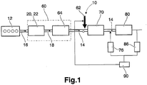
- a preferred exhaust gas after treatment system 10 depicted in Fig. 1 comprises a diesel particulate filter unit (DPFU) 60 arranged downstream of a diesel engine 12 and a NO x reducing unit 70 such as preferably a selective-catalytic-reduction (SCR) arrangement arranged downstream of said DPFU 60, wherein an injector 62 is provided for feeding reducing agent such as ammonia or urea into the exhaust gas and arranged downstream of said DPFU 60 and upstream said SCR catalyst. Downstream said SCR 70 is provided a clean up catalyst 80.
- the DPFU 60 comprises an oxidation catalyst stage (DOCS) 20, e.g.
- DOCS oxidation catalyst stage
- DOC oxidation catalyst
- DPF diesel particulate filter
- the DPF 64 can exhibit an oxidizing catalytic coating which can replace the DOC 22 as oxidation stage 20 or which can at least support the DOC 22.
- the clean-up catalyst 80 is used to clean-up excess of ammonia by reaction (R1). Partial oxidation of ammonia, given by reactions (R2) and (R3), may produce nitrous oxide (N 2 O) or elemental nitrogen, respectively. Complete oxidation of ammonia, expressed by reaction (R4), generates nitric oxide (NO).
- the catalyst consists of a metal oxide and some noble metal and could be coated on a similar structure as the SCR catalyst or on even on the same structure.
- a second NOx sensor 76 is provided between the SCR 70 and the clean up catalyst 80.
- a first NOx sensor 86 is provided downstream the clean up catalyst 80.
- the second NOx sensor 76 measures the NOx coming from the SCR 70.
- the first NOx sensor 86 measures the NOx coming from the SCR 70 and possibly the NOx created by the clean up catalyst 80.
- a control unit 90 compares the NOx values from the second NOx sensor 76 with the NOx values from the first NOx sensor 86. If the first NOx sensor 86 has detected a higher NOx content in the exhaust gases than the second NOx sensor 76 it is an indication that the clean up catalyst has transformed urea slip in the exhaust gases into NOx detected by said first NOx sensor 86.
- this first NOx sensor 86 is in fact detecting a higher NOx value than the second NOx sensor 76, a signal is sent the the urea injector 62 to decrease the urea injection by a predetermined amount.
- the feed back signal from the control unit to the urea injector may ensure that the correct amount of urea is injected to the SCR regardless of its storage capacity, operating conditions, deterioration of system performance and/or its age and at the same time keep the NOx levels at a low level.
- This feed back loop may significantly reduce the need for continuous calibration of the SCR system since it is selfcalibrated by said feed back signal from the control unit to the urea injector.
- the inventive method may also be used as a detection method of a malfunctioning and/or poisoned SCR. If abnormal amount of NOx is created by the clean up catalyst then one may suspect that the SCR system is not performing as it should.
- the amount of urea may be adjusted by sending a steering signal from the control unit 90 to the urea injector 62 which may decrease the opening time of the urea injector, decrease the frequency of a pulsated injection or a combination of said methods or any other well known method of adjusting the amount of an injector.
- a look up table may be used in order to determine the degree of reduced urea amount related to the difference in NOx measured by the first NOx sensor and the second NOx sensor.
- This table may comprise predetermined amounts of reduced urea injections corresponding to detected differences by said NOx sensors, i.e., a detected ⁇ NOx may correspond to a predetermined decreased amount of urea injection.
- the use of a first and a second NOx sensor after the SCR may result in increased robustness of tail pipe NOx control and assist in OBD (On Board Diagnosis) functions.
- the first and second NOx sensor may also significantly increase the accuracy of the estimation of NH3 storage in the SCR. Hence, the need for continuous calibration of the SCR buffer models may be reduced.
- the first and second NOx sensors also have the ability to detect ammonia slip. Hence, a more accurate and self adjusted urea injection for aged and reduced performance SCR catalyst may be accomplished while at the same time maintaining low NOx.
- Said urea amount may also be reduced in predetermined increments until the NOx measured by said first NOx sensor 86 subtracted by the NOx measured by the second NOx sensor 76 is smaller than a predetermined ⁇ NOx.
- the predetermined increments may be equal increments or larger in the beginning of the reduction than in the end of said reduction.
- the DOCS 20, i.e. the DOC 22 and/or the catalytic coating of the DPF 64, is preferably used to generate a sufficient amount of NO 2 for passive oxidation of soot trapped in the DPF 64 according to the reaction (R5) NO+NO 2 ⁇ NO 2 .
- the main function of the DPF 64 is to trap particulate matter such as soot and ashes contained in the exhaust gas.
- a typical vehicular exhaust aftertreatment system 10 requires one to several 100 000 km driving to fill the DPF 64 with ashes, and the DPF 64 can be emptied from ash by demounting the DPF 64 at service.
- To fill the DPF 64 with soot requires only one to several 1000 km driving.
- the soot can be oxidized to CO 2 which can be done during operation of the vehicle.
- the DPF 64 may be beneficial to coat with a catalytically active material including the properties of an oxidation catalyst into the DPF 64.
- a catalytically active material including the properties of an oxidation catalyst into the DPF 64.
- Regeneration of the DPF 64 may be accomplished in various ways known in the art.
- NO 2 can be used for passive oxidation of the trapped soot according to the reaction is (R6) 2NO 2 +C ⁇ 2NO+CO 2 .
- the amount of NO 2 in the exhaust gas fed into the DPF 64 can be increased by the DOCS 20 by oxidation of NO to NO 2 .
- the passive oxidation of soot can keep the soot level in the DPF 64 low at exhaust temperatures above 250°C. For some engine emissions the ratio of NO x /soot is too low for oxidizing the soot by NO 2 .
- Alternative to passive oxidation of soot it can be oxidized by oxygen at high temperatures, preferably at about 600°C. This can be achieved by either providing a burner (not shown) in the exhaust aftertreatment system 10 or by adding fuel to the exhaust gas which is burnt on an oxidation catalyst (not shown) upstream of the DPF 64. Activation of the burner or adding fuel is done in a regeneration phase which has a typical duration of a few minutes and which can last as long as 30 min if necessary.
- the exhaust gas Downstream of the DPF 64 and upstream of the nitrogen-oxides reduction unit 70, by way of example an SCR catalyst, the exhaust gas contains one or more constituents as NO and NO 2 , which can be deoxidized in the SCR catalyst.
- the main task of the SCR catalyst is to reduce NO x , i.e. NO and NO 2 , with a reductant to nitrogen gas N 2 and water H 2 O.
- NO x i.e. NO and NO 2
- ammonia NH 3 reacts with NO x to form nitrogen.
- urea is injected into the exhaust gas and by the exhaust gas temperature urea is thermolyzed or hydrolyzed into NH 3 in the exhaust gas and the SCR catalyst.
- the reductant e.g. NH 3 or urea
- the efficiency of the SCR catalyst is strongly dependent on the exhaust gas temperature, the space velocity of the exhaust gas and the NO 2 /NO ratio in the exhaust gas which enters the SCR catalyst.
- reaction (R7) has the highest efficiency and is efficient from exhaust temperatures below 200°C and above.
- Reaction (a) becomes efficient at 300°C and for reaction (c) the efficiency is lower than reaction (a) on vanadium based SCR-catalyst while it is on zeolite-based catalyst more efficient than reaction (a) but not as efficient as reaction (b).
- an unfavourable competitive reaction to reaction (c) exist which is generating the greenhouse gas N 2 O: (R10) 4NO2 + 4NH 3 ⁇ 2N 2 O + 2N 2 + 6H 2 O.
- the NO 2 formation in the DOCS 20 will depend on the exhaust gas mass flow and the temperature of the DOCS 20. Besides the flow and temperature dependency, the DOC 22 and/or the catalytic coating in the DPF 64 adsorbs sulphur (S), which can be contained in the exhaust gas, at lower temperatures and releases the sulphur at temperatures above 350°C. If driving conditions let the DOCS 20 adsorb a lot of sulphur, the NO 2 formation will be poisoned.
- S sulphur
- the NO 2 content after the DPF 64 will also depend on the condition of the DPF 64.
- Sulphur is the main source to deactivate NO 2 formation on the DOC 22 and on the catalytic coating of the DPF 64. Sulphur sticks to the catalyst at lower temperatures, typically below 400°C and is released at higher temperatures (> 400°C). The actual temperatures for sulphur adsorption and desorption depend on the particular catalyst formulation.
- Sulphur is removed from the DOC 22 and/or the coated DPF 64 by heating the catalysts to above 400°C for more than 5 minutes, which can be done by injecting fuel into the exhaust or by activating a burner.
- Another source of sulphur is the lubricant oil.
- Some conditions on some catalytic materials can cause a reversible degradation of the DOCS 20 in a manner that can it be reconditioned when heated to high temperatures above e.g. 500°C for a predetermined time period, e.g. several minutes.
- the desulphatisation temperature does not degrade the SCR-catalyst and during desulphatisation the SCR-catalyst gets a temperature where it works very efficient and the influence of NO 2 /NO ratio is low.
- the description of the virtual sensor is a map or physical model of the NO 2 formation in the DOC 22 and optionally in the DPF 64 if it's coated and on the NO 2 consumption in the DPF 64.
- the sulphur dependency of the NO 2 will not be included in the model since this invention is a way of handling the sulphur effect on NO 2 (and it's hard to model also due to unknown variations of sulphur content in the fuel (low-sulphur fuel could be any thing below 10ppm in Europe for example).
- NO x conversion may be used for on-board-diagnosis of the correct function of the DOCS 20, i.e. the DOC 22 and/or the oxidizing catalytic coating of the DPF 64, if the DPF 64 is provided with such a coating.
- the NO x conversion is derived from temperature, exhaust gas mass flow and NO 2 levels in the exhaust gas.
- the NO x sensor can be a real, physical sensor or a virtual sensor wherein the NO x level is calculated based on an appropriate model described below.
- exhaust gas flow The exhaust gas flow can be measured, or derived from the measured air intake flow and the fuel amount, or from the calculated air intake flow from engine speed, intake air pressure, intake air temperature, EGR amount and volumetric efficiency of the engine.
- exhaust gas flow in oxidation catalyst The exhaust gas flow in the DOCS 20 can be measured or calculated.
- Temperature in catalyst The temperature can e.g. be measured upstream of the DOCS 20. By applying an appropriate signal filter the measured value together with the exhaust gas flow into the DOCS 20 as a parameter can represent the actual catalyst temperature. Alternatively the temperature can be calculated by using a simple heat balance.
- the parameter "sulphur adsorbed from exhaust during a second” is the sulphur content in the fuel and lubrication oil consumed during the said second multiplied with a factor, wherein the factor is between 0 and 1 and has a temperature dependency which can e.g. be derived from a map containing temperature dependent values of the factor.
- the parameter "sulphur desorbed during a second” is the sulphur content in the DOCS 20 one second before multiplied with another temperature dependent factor which can be derived in the same way as the first factor described above.
- NO 2 formation in catalyst The NO 2 formation in the DOCS 20 can be derived from interpolating in a 3-D based on the parameters exhaust gas flow, temperature in catalyst and sulphur content. It can also be calculated using a physical model with sulphur content, temperature, exhaust gas flow and oxygen concentration as input parameters.
- the model can be e.g. a specific NO 2 formation rate which is k 1 ⁇ C NO ⁇ C O2 and an NO 2 decomposition rate which is k 2 ⁇ C NO2 , where k 1 and k 2 are temperature dependent and sulphur-content dependent parameters and C is the concentration of NO, NO 2 and O 2 , respectively.
- the specific rate is integrated over the catalyst volume.
- the HC level is also an input parameter to the model, e.g. as a denominator for the specific rates (1 + K a ⁇ C HC ).
- NO 2 out from the particulate filter The amount NO 2 which is released from the DPF 64 is the difference between the amount of NO 2 fed into the DPF 64, NO 2 formed in the DPF 64 (which is zero if no catalytic layer is provided in the DPF 64 for NO 2 generation) and NO 2 consumed by soot in the DPF 64.
- NO 2 formed in the DPF 64 can be calculated in the same manner as the NO 2 formed in the DOCS 20 (see above), preferably a physical model.
- NO 2 consumed by soot in the DPF 64 is proportional to the amount of soot in the DPF 64 and can be expressed as a specific rate k 3 ⁇ C NO2 ⁇ C soot . Again, k 3 is a temperature dependent parameter and C the respective concentration of NO 2 and soot.
- the usage of a pressure drop for calculation of a soot amount in the DPF 64 can introduce some errors due to the fact that the soot characteristic is changing with time. Therefore it is preferred to use a model for calculating the soot load and use the pressure drop as a qualitative check of the model.
- an actual measured and estimated conversion of NO 2 in the DPFU 60 and conversion NO x in the SCR catalyst can be derived.
- the NO x content upstream of the nitrogen-oxides reduction unit 70 can be measured or calculated. Downstream of the nitrogen-oxides reduction unit 70 the NO x content is measured and calculated. A difference between the measured and the calculated contents indicates that a problem with the NO oxidation in the DPFU 60 has occurred.
- the NO 2 content in the exhaust gas yielding an estimated NO 2 content upstream of the nitrogen-oxides reduction unit 70 and to calculate and/or to measure an expected NO x content upstream of the nitrogen-oxides reduction unit 70. Downstream of the nitrogen-oxides reduction unit 70 the NO x content is measured and calculated.
- One or more temperatures sensors are provided at convenient locations for determining the catalysts temperatures.
- the NO x -conversion is determined based on these values and on the temperature, exhaust gas massflow and the estimated NO 2 content.
Description
- The invention relates to a control method for an exhaust aftertreatment system according to the preambles of the independent claims.
- Present regulatory conditions in the automotive market have led to an increasing demand to improve fuel economy and reduce emissions in present vehicles. These regulatory conditions must be balanced with the demands of a consumer for high performance and quick response for a vehicle.
- A diesel engine has an efficiency of up to about 52% and is thus the best converter of fossil energy. NOx emission concentration, i.e. the emission of nitrogen oxides NO and NO2, is dependent upon local oxygen atom concentration and the local temperature. Said high efficiency is however only possible at an elevated combustion temperature at which high NOx levels are inevitable. Moreover, a suppression of NOx formation by internal means (air/fuel ratio) has the tendency to cause an increase in particulates, known as the NOx -particulates trade off. Furthermore, an excess of oxygen in the exhaust gas from a diesel engine prevents the use of stoichiometric 3-way-catalyst technology for reduction of NOx as is used in gasoline engine cars from the late 80-ties.
- Both carbon particulates and NOx are typical emissions in the exhaust gas of diesel engines. Requirements for reducing such emissions increase and trigger various approaches in the art to reduce emissions. In the European patent
EP 1 054 722 B1 an exhaust aftertreatment system is disclosed which combines a particulate filter collecting soot and nitrogen-oxides reduction catalysts in the exhaust tract. For removing soot NO2 is generated by oxidation of NO in an oxidation catalyst. Soot which is collected in a particulate filter is oxidized by NO2. Residual amounts of NO and NO2 in the exhaust gas are reduced to nitrogen gas in a selective-catalytic-reduction catalyst (SCR catalyst) by injecting ammonia into the SCR catalyst. - During operation all catalysts degrade due to accumulation of poisons, thermal migration of the catalyst material etc. This degradation seriously influences the operation of aftertreatment systems. Therefore it is desirable to detect the degradation of a catalyst in the aftertreatment system before the operation of the aftertreatment system fails or legal requirements cannot be fulfilled because of the degradation.
- According to its abstract,
JP2008 255899 A ammonia oxidation catalyst 14 having the function of oxidizing ammonia is installed in the exhaust passage 6 of the internal combustion engine 1 and the amount of N2O generated in theammonia oxidation catalyst 14 is estimated based on the difference between the value detected by an upstream side NOx sensor 17 installed in the exhaust passage 6 on the downstream side of theammonia oxidation catalyst 14 and the value detected by a downstreamside NOx sensor 18 installed in the exhaust passage on the downstream side of theammonia oxidation catalyst 14. - It is an object of the invention to provide an improved exhaust aftertreatment system control method. It is another object of the invention to provide an adequate improved exhaust aftertreatment system.
- The objects are achieved by the features of the independent claims. The other claims and the description disclose advantageous embodiments of the invention.
- In a first aspect of the present invention it is provided a method for an exhaust aftertreatment system (10) of an engine (12) comprising at least one selective catalyst reaction (SCR) at least one clean up catalyst downstream said SCR, an urea injector upstream said SCR and a first NOx sensor downstream said clean up catalyst, the method comprising the steps of injecting a predetermined amount of urea by said injector, providing a second NOx sensor between said SCR and said clean up catalyst, measuring the NOx content received by said first NOx sensor, measuring the NOx content received by said second NOx sensor, comparing said first and said second NOx content with each other, reducing the predetermined amount of urea if said first NOx sensor is measuring a higher NOx content than said second NOx sensor.
- An advantage with this embodiment of the present invention is that it gives to possibility to detect ammonia slip and control ammonia/urea injection directly, while at the same time maintaining low NOx.
- Another advantage of the present invention is that it significantly reduces the need for continuous calibration of the SCR models. The accuracy of estimated stored NH3 increases when the ammonia slip after the SCR Is either estimated or measured.
- Yet another advantage of the present invention is that it compensated for ageing and deterioration of system performance.
- Still another advantage of the present invention is that it gives the possibility to detect system malfunctioning/poisoning.
- In another example embodiment of the present invention it is further comprising a look up table having a reduced urea amount related to the difference in NOx measured by the first NOx sensor and the second NOx sensor.
- An advantage of this embodiment is that the amount of urea can more quickly be adapted and adjusted to the current circumstances compared to a feed back loop which is the other possibility.
- In still another example embodiment according to the present invention said urea amount is reduced in predetermined increments until the NOx measured by said first NOx sensor subtracted by the NOx measured by the second NOx sensor is smaller than a predetermined ΔNOx.
- An advantage of this embodiment is that no prior measurements need to be done, the diagnostic method is self calibrating.
- In another aspect of the present invention it is provided an exhaust after treatment system comprising at least one selective catalyst reaction (SCR) at least one clean up catalyst downstream said SCR, an urea injector upstream said SCR and a first NOx sensor downstream said clean up catalyst, characterized by a second NOx sensor provided between said SCR and said clean up catalyst.
- In yet another example embodiment of the present invention it further comprising a control unit for comparing the detected NOx values from said first and second NOx sensors, wherein said control unit further comprising means for controlling the amount of urea injected by said urea injector where said amount of urea is dependent on the NOx values from said first and second NOx sensors.
- The present invention together with the above-mentioned and other objects and advantages may best be understood from the following detailed description of the embodiments, but not restricted to the embodiments, wherein is shown schematically:
- Fig. 1
- a first embodiment of an exhaust aftertreatment system according to the invention;
- In the drawings, equal or similar elements are referred to by equal reference numerals. The drawings are merely schematic representations, not intended to portray specific parameters of the invention. Moreover, the drawings are intended to depict only typical embodiments of the invention and therefore should not be considered as limiting the scope of the invention.
- According to a first aspect of the invention a preferred exhaust gas after
treatment system 10 depicted inFig. 1 comprises a diesel particulate filter unit (DPFU) 60 arranged downstream of adiesel engine 12 and a NOx reducing unit 70 such as preferably a selective-catalytic-reduction (SCR) arrangement arranged downstream of saidDPFU 60, wherein aninjector 62 is provided for feeding reducing agent such as ammonia or urea into the exhaust gas and arranged downstream of said DPFU 60 and upstream said SCR catalyst. Downstream said SCR 70 is provided a clean upcatalyst 80. TheDPFU 60 comprises an oxidation catalyst stage (DOCS) 20, e.g. an oxidation catalyst (DOC) 22 and a diesel particulate filter (DPF) 64, which is arranged downstream of the DOC 22. Optionally, theDPF 64 can exhibit an oxidizing catalytic coating which can replace the DOC 22 as oxidation stage 20 or which can at least support the DOC 22. - The clean-
up catalyst 80 is used to clean-up excess of ammonia by reaction (R1). Partial oxidation of ammonia, given by reactions (R2) and (R3), may produce nitrous oxide (N2O) or elemental nitrogen, respectively. Complete oxidation of ammonia, expressed by reaction (R4), generates nitric oxide (NO). The catalyst consists of a metal oxide and some noble metal and could be coated on a similar structure as the SCR catalyst or on even on the same structure.
(R1) 4 NH3 + 3 O2 -> 2 N2 + 6 H2O
(R2) 2NH3 + 2 O2 -> N2O + 3 H2O
(R3) 4NH3 + 3 O2 -> 2N2 + 6 H2O
(R4) 4NH3 + 5 O2 -> 4NO + 6 H2O
- A
second NOx sensor 76 is provided between theSCR 70 and theclean up catalyst 80. Afirst NOx sensor 86 is provided downstream theclean up catalyst 80. Thesecond NOx sensor 76 measures the NOx coming from theSCR 70. Thefirst NOx sensor 86 measures the NOx coming from theSCR 70 and possibly the NOx created by the clean upcatalyst 80. Acontrol unit 90 compares the NOx values from thesecond NOx sensor 76 with the NOx values from thefirst NOx sensor 86. If thefirst NOx sensor 86 has detected a higher NOx content in the exhaust gases than thesecond NOx sensor 76 it is an indication that the clean up catalyst has transformed urea slip in the exhaust gases into NOx detected by saidfirst NOx sensor 86. If thisfirst NOx sensor 86 is in fact detecting a higher NOx value than thesecond NOx sensor 76, a signal is sent the theurea injector 62 to decrease the urea injection by a predetermined amount. The feed back signal from the control unit to the urea injector may ensure that the correct amount of urea is injected to the SCR regardless of its storage capacity, operating conditions, deterioration of system performance and/or its age and at the same time keep the NOx levels at a low level. This feed back loop may significantly reduce the need for continuous calibration of the SCR system since it is selfcalibrated by said feed back signal from the control unit to the urea injector. The inventive method may also be used as a detection method of a malfunctioning and/or poisoned SCR. If abnormal amount of NOx is created by the clean up catalyst then one may suspect that the SCR system is not performing as it should. - The amount of urea may be adjusted by sending a steering signal from the
control unit 90 to theurea injector 62 which may decrease the opening time of the urea injector, decrease the frequency of a pulsated injection or a combination of said methods or any other well known method of adjusting the amount of an injector. - A look up table may be used in order to determine the degree of reduced urea amount related to the difference in NOx measured by the first NOx sensor and the second NOx sensor. This table may comprise predetermined amounts of reduced urea injections corresponding to detected differences by said NOx sensors, i.e., a detected ΔNOx may correspond to a predetermined decreased amount of urea injection.
- The use of a first and a second NOx sensor after the SCR may result in increased robustness of tail pipe NOx control and assist in OBD (On Board Diagnosis) functions. The first and second NOx sensor may also significantly increase the accuracy of the estimation of NH3 storage in the SCR. Hence, the need for continuous calibration of the SCR buffer models may be reduced. The first and second NOx sensors also have the ability to detect ammonia slip. Hence, a more accurate and self adjusted urea injection for aged and reduced performance SCR catalyst may be accomplished while at the same time maintaining low NOx.
- Said urea amount may also be reduced in predetermined increments until the NOx measured by said
first NOx sensor 86 subtracted by the NOx measured by thesecond NOx sensor 76 is smaller than a predetermined ΔNOx. The predetermined increments may be equal increments or larger in the beginning of the reduction than in the end of said reduction. - The DOCS 20, i.e. the DOC 22 and/or the catalytic coating of the
DPF 64, is preferably used to generate a sufficient amount of NO2 for passive oxidation of soot trapped in theDPF 64 according to the reaction
(R5) NO+NO2→NO2.
- The main function of the
DPF 64 is to trap particulate matter such as soot and ashes contained in the exhaust gas. A typical vehicularexhaust aftertreatment system 10 requires one to several 100 000 km driving to fill theDPF 64 with ashes, and theDPF 64 can be emptied from ash by demounting theDPF 64 at service. To fill theDPF 64 with soot requires only one to several 1000 km driving. However, the soot can be oxidized to CO2 which can be done during operation of the vehicle. - For some applications it may be beneficial to coat the
DPF 64 with a catalytically active material including the properties of an oxidation catalyst into theDPF 64. For proper function of theDPF 64 it is recommended to control the amount of soot trapped in theDPF 64. Regeneration of theDPF 64 may be accomplished in various ways known in the art. Preferably, NO2 can be used for passive oxidation of the trapped soot according to the reaction is
(R6) 2NO2+C→2NO+CO2.
- For an efficient passive regeneration it is necessary to establish the exhaust gas temperature above a critical limit, preferably above 250°C, and to provide an adequate amount of NO2. The amount of NO2 in the exhaust gas fed into the
DPF 64 can be increased by the DOCS 20 by oxidation of NO to NO2. - Depending in the
engine 12 emissions of soot and nitrogen oxides NO, NO2, generally referred to as NOx, the passive oxidation of soot can keep the soot level in theDPF 64 low at exhaust temperatures above 250°C. For some engine emissions the ratio of NOx/soot is too low for oxidizing the soot by NO2. Alternative to passive oxidation of soot it can be oxidized by oxygen at high temperatures, preferably at about 600°C. This can be achieved by either providing a burner (not shown) in theexhaust aftertreatment system 10 or by adding fuel to the exhaust gas which is burnt on an oxidation catalyst (not shown) upstream of theDPF 64. Activation of the burner or adding fuel is done in a regeneration phase which has a typical duration of a few minutes and which can last as long as 30 min if necessary. - Downstream of the
DPF 64 and upstream of the nitrogen-oxides reduction unit 70, by way of example an SCR catalyst, the exhaust gas contains one or more constituents as NO and NO2, which can be deoxidized in the SCR catalyst. - The main task of the SCR catalyst is to reduce NOx, i.e. NO and NO2, with a reductant to nitrogen gas N2 and water H2O. On the SCR catalyst ammonia NH3 reacts with NOx to form nitrogen. Usually on vehicles urea is injected into the exhaust gas and by the exhaust gas temperature urea is thermolyzed or hydrolyzed into NH3 in the exhaust gas and the SCR catalyst. The reductant, e.g. NH3 or urea, is added to the exhaust gas upstream of the SCR catalyst, for instance by the injector 62 (indicated by a broad arrow upstream of the SCR catalyst). The efficiency of the SCR catalyst is strongly dependent on the exhaust gas temperature, the space velocity of the exhaust gas and the NO2/NO ratio in the exhaust gas which enters the SCR catalyst.
- Depending on the kind of NOx there are three principal chemical reactions possible:
(R7) 4NO + 4NH3 + O2 → 4N2 + 6H2O
(R8) NO + NO2 + 2NH3 → 2N2 + 3H2O
(R9) 6NO2 + 8NH3 → 7N2 + 12H2O
- The reaction (R7) has the highest efficiency and is efficient from exhaust temperatures below 200°C and above. Reaction (a) becomes efficient at 300°C and for reaction (c) the efficiency is lower than reaction (a) on vanadium based SCR-catalyst while it is on zeolite-based catalyst more efficient than reaction (a) but not as efficient as reaction (b). Further, on zeolite-based catalyst an unfavourable competitive reaction to reaction (c) exist which is generating the greenhouse gas N2O:
(R10) 4NO2 + 4NH3 → 2N2O + 2N2 + 6H2O.
- The NO2 formation in the DOCS 20 will depend on the exhaust gas mass flow and the temperature of the DOCS 20. Besides the flow and temperature dependency, the DOC 22 and/or the catalytic coating in the
DPF 64 adsorbs sulphur (S), which can be contained in the exhaust gas, at lower temperatures and releases the sulphur at temperatures above 350°C. If driving conditions let the DOCS 20 adsorb a lot of sulphur, the NO2 formation will be poisoned. The NO2 content after theDPF 64 will also depend on the condition of theDPF 64. - Sulphur is the main source to deactivate NO2 formation on the DOC 22 and on the catalytic coating of the
DPF 64. Sulphur sticks to the catalyst at lower temperatures, typically below 400°C and is released at higher temperatures (> 400°C). The actual temperatures for sulphur adsorption and desorption depend on the particular catalyst formulation. - When low sulphur diesel fuel is used, which is now generally available in Europe and USA, it will take several hours or a day of engine operation without reaching 400°C to give a noticeable decrease in NO2 formation in the DOC 20 and/or the
coated DPF 64. Such driving is unusual with heavy duty vehicles but can occur. However, sulphur poisoning of the DOC 22 and/or thecoated DPF 64 can occur after shorter times if the driver gets fuel with higher sulphur contents, e.g. when driving in markets without low-sulphur fuel or fuelling high sulphur fuel by mistake. It's then important to detect such a poisoning and make a desulphation of the DOCS 22. Sulphur is removed from the DOC 22 and/or thecoated DPF 64 by heating the catalysts to above 400°C for more than 5 minutes, which can be done by injecting fuel into the exhaust or by activating a burner. Another source of sulphur is the lubricant oil. - Some conditions on some catalytic materials can cause a reversible degradation of the DOCS 20 in a manner that can it be reconditioned when heated to high temperatures above e.g. 500°C for a predetermined time period, e.g. several minutes.
- The desulphatisation temperature does not degrade the SCR-catalyst and during desulphatisation the SCR-catalyst gets a temperature where it works very efficient and the influence of NO2/NO ratio is low.
- The description of the virtual sensor is a map or physical model of the NO2 formation in the DOC 22 and optionally in the
DPF 64 if it's coated and on the NO2 consumption in theDPF 64. The sulphur dependency of the NO2 will not be included in the model since this invention is a way of handling the sulphur effect on NO2 (and it's hard to model also due to unknown variations of sulphur content in the fuel (low-sulphur fuel could be any thing below 10ppm in Europe for example). - NOx conversion may be used for on-board-diagnosis of the correct function of the DOCS 20, i.e. the DOC 22 and/or the oxidizing catalytic coating of the
DPF 64, if theDPF 64 is provided with such a coating. The NOx conversion is derived from temperature, exhaust gas mass flow and NO2 levels in the exhaust gas. The NOx sensor can be a real, physical sensor or a virtual sensor wherein the NOx level is calculated based on an appropriate model described below. - A virtual NOx sensor is a rather complex model and consists preferably of following sub-models which are given in quotes:
"Engine-out NO x ": The amount of NOx at the outlet of theengine 12 can be estimated by a sensor or a model with following inputs for example: load or fuel amount, timing for fuel injection, engine speed, intake air pressure, intake air temperature, EGR (EGR = exhaust gas recycling) amount and intake air humidity. These are parameters of theengine 12 and sensed values. There are several ways to build the model. It can be map-based where all or at least some of the relevant parameters are, or can be, corrected by correction factors laid down in the map. It can also be a model built on a neural network as base. - "Exhaust gas flow": The exhaust gas flow can be measured, or derived from the measured air intake flow and the fuel amount, or from the calculated air intake flow from engine speed, intake air pressure, intake air temperature, EGR amount and volumetric efficiency of the engine.
- "Exhaust gas flow in oxidation catalyst": The exhaust gas flow in the DOCS 20 can be measured or calculated.
- "Temperature in catalyst": The temperature can e.g. be measured upstream of the DOCS 20. By applying an appropriate signal filter the measured value together with the exhaust gas flow into the DOCS 20 as a parameter can represent the actual catalyst temperature. Alternatively the temperature can be calculated by using a simple heat balance.
- "Sulphur in oxidation catalyst": The sulphur content in the DOCS 20 is preferably calculated. For instance the calculation can be derived from the parameters in parentheses: (sulphur content in catalyst)=(sulphur content in catalyst a second before) + (sulphur adsorbed from exhaust during a second) - (sulphur desorbed during a second). The parameter "sulphur adsorbed from exhaust during a second" is the sulphur content in the fuel and lubrication oil consumed during the said second multiplied with a factor, wherein the factor is between 0 and 1 and has a temperature dependency which can e.g. be derived from a map containing temperature dependent values of the factor. The parameter "sulphur desorbed during a second" is the sulphur content in the DOCS 20 one second before multiplied with another temperature dependent factor which can be derived in the same way as the first factor described above.
- "NO 2 formation in catalyst": The NO2 formation in the DOCS 20 can be derived from interpolating in a 3-D based on the parameters exhaust gas flow, temperature in catalyst and sulphur content. It can also be calculated using a physical model with sulphur content, temperature, exhaust gas flow and oxygen concentration as input parameters. The model can be e.g. a specific NO2 formation rate which is k1·CNO·CO2 and an NO2 decomposition rate which is k2·CNO2, where k1 and k2 are temperature dependent and sulphur-content dependent parameters and C is the concentration of NO, NO2 and O2, respectively. The specific rate is integrated over the catalyst volume. If there is a wide range of the HC content in the engine's working area or if an HC-injector is used, then the HC level is also an input parameter to the model, e.g. as a denominator for the specific rates (1 + Ka·CHC).
- "NO 2 out from the particulate filter": The amount NO2 which is released from the
DPF 64 is the difference between the amount of NO2 fed into theDPF 64, NO2 formed in the DPF 64 (which is zero if no catalytic layer is provided in theDPF 64 for NO2 generation) and NO2 consumed by soot in theDPF 64. NO2 formed in theDPF 64 can be calculated in the same manner as the NO2 formed in the DOCS 20 (see above), preferably a physical model. NO2 consumed by soot in theDPF 64 is proportional to the amount of soot in theDPF 64 and can be expressed as a specific rate k3·CNO2·Csoot. Again, k3 is a temperature dependent parameter and C the respective concentration of NO2 and soot. - "Soot load in particulate filter": The soot load in
DPF 64 can be derived from a measured pressure drop over theDPF 64 and/or by applying a model: (soot in theDPF 64 at a current time) = (soot in theDPF 64 at a time before the current time) + (soot emitted by the engine during the current time) - (soot burnt by NO2 during the current time). Soot burnt by NO2 during the current time is given by the "NO2 out from particulate filter" model, soot emitted by the engine during the current time is given from a soot sensor or a similar model as the "Engine-out NOx" model. - The usage of a pressure drop for calculation of a soot amount in the
DPF 64 can introduce some errors due to the fact that the soot characteristic is changing with time. Therefore it is preferred to use a model for calculating the soot load and use the pressure drop as a qualitative check of the model. - From estimating NO2 and NOx contents in the exhaust gas at different locations an actual measured and estimated conversion of NO2 in the
DPFU 60 and conversion NOx in the SCR catalyst can be derived. At high loads it is preferred to measure the NO2 content in the exhaust gas upstream of the nitrogen-oxides reduction unit 70 and to calculate, i.e. estimate an expected NO2 content upstream of the nitrogen-oxides reduction unit 70. Additionally, the NOx content upstream of the nitrogen-oxides reduction unit 70 can be measured or calculated. Downstream of the nitrogen-oxides reduction unit 70 the NOx content is measured and calculated. A difference between the measured and the calculated contents indicates that a problem with the NO oxidation in theDPFU 60 has occurred. - At low loads it is preferred to calculate the NO2 content in the exhaust gas yielding an estimated NO2 content upstream of the nitrogen-
oxides reduction unit 70 and to calculate and/or to measure an expected NOx content upstream of the nitrogen-oxides reduction unit 70. Downstream of the nitrogen-oxides reduction unit 70 the NOx content is measured and calculated. - One or more temperatures sensors (not shown) are provided at convenient locations for determining the catalysts temperatures.
- The NOx-conversion is determined based on these values and on the temperature, exhaust gas massflow and the estimated NO2 content.
Claims (7)
- A method for an exhaust aftertreatment system (10) of an engine (12) comprising at least one selective catalyst reaction (SCR), at least one clean up catalyst (80) downstream said SCR (70), an urea injector (62) upstream said SCR (70) and a first NOx sensor (86) downstream said clean up catalyst (80), the method comprising the steps of(a) injecting a predetermined amount of urea by said injector,(b) providing a second NOx sensor (76) between said SCR (70) and said clean up catalyst (80),(c) measuring the NOx content received by said first NOx sensor (86),(d) measuring the NOx content received by said second NOx sensor (76),(e) comparing said first and said second NOx content with each other, characterized by(f) reducing the predetermined amount of urea if said first NOx sensor (86) is measuring a higher NOx content than said second NOx sensor (76).
- The method according to claim 1, further comprising a look up table having a reduced urea amount related to the difference in NOx measured by the first NOx sensor (86) and the second NOx sensor (76).
- The method according to claim 1, wherein said urea amount is reduced in predetermined increments until the NOx measured by said first NOx sensor (86) subtracted by the NOx measured by the second NOx sensor (76) is smaller than a predetermined ΔNOx.
- A use of the method according to any one of claim 1-3 for compensating for ageing and/or deterioration of exhaust after treatment system performance.
- A use of the method according to any one of claim 1-3 for detecting SCR (70) malfunctioning and/poisoning.
- A use of the method according to any one of claim 1-3 for estimating the ammonia storage capacity in the SCR (70).
- An exhaust after treatment system comprising at least one selective catalyst reaction (SCR (70)), at least one clean up catalyst (80) downstream said SCR (70), an urea injector (62) upstream said SCR (70), a first NOx sensor (86) downstream said clean up catalyst (80) and a second NOx sensor (76) provided between said SCR (70) and said clean up catalyst (80), said exhaust after treatment system further comprising a control unit (90) for comparing the detected NOx values from said first and second NOx sensors (86, 76), wherein said control unit further comprising means for controlling the amount of urea injected by said urea injector (62) where said amount of urea is dependent on the NOx values from said first and second NOx sensors (86, 76), characterized in that said control unit (90) is adapted to send a signal to the urea injector (62) to decrease the urea injection by a predetermined amount if the first NOx sensor (86) detects a higher NOx value than the second NOx sensor (76).
Applications Claiming Priority (1)
| Application Number | Priority Date | Filing Date | Title |
|---|---|---|---|
| PCT/SE2008/000697 WO2010068147A1 (en) | 2008-12-12 | 2008-12-12 | Scr closed loop control system |
Publications (3)
| Publication Number | Publication Date |
|---|---|
| EP2376750A1 EP2376750A1 (en) | 2011-10-19 |
| EP2376750A4 EP2376750A4 (en) | 2015-05-27 |
| EP2376750B1 true EP2376750B1 (en) | 2018-10-03 |
Family
ID=42242941
Family Applications (1)
| Application Number | Title | Priority Date | Filing Date |
|---|---|---|---|
| EP08878782.5A Active EP2376750B1 (en) | 2008-12-12 | 2008-12-12 | Scr closed loop control system |
Country Status (3)
| Country | Link |
|---|---|
| US (1) | US8893476B2 (en) |
| EP (1) | EP2376750B1 (en) |
| WO (1) | WO2010068147A1 (en) |
Families Citing this family (17)
| Publication number | Priority date | Publication date | Assignee | Title |
|---|---|---|---|---|
| DE102009022882A1 (en) * | 2009-05-27 | 2010-12-02 | Bayerische Motoren Werke Aktiengesellschaft | A sensor for detecting the amount of a reducing agent and the amount of a pollutant in an exhaust gas |
| BR112012014614B1 (en) * | 2009-12-18 | 2020-12-08 | Volvo Lastvagnar Ab | method for controlling a fill level of a reducer buffer level |
| US8869512B2 (en) | 2011-04-06 | 2014-10-28 | Commins Inc. | Combined engine out NOX management |
| US20130000276A1 (en) * | 2011-06-30 | 2013-01-03 | Caterpillar Inc. | Virtual reductant quality sensor |
| DE102012201749B4 (en) * | 2012-02-07 | 2024-02-15 | Robert Bosch Gmbh | Method for monitoring an SCR catalytic converter |
| WO2013152780A1 (en) | 2012-04-10 | 2013-10-17 | Volvo Lastvagnar Ab | A self-diagnosing method for diagnosing a scr system |
| SE538378C2 (en) * | 2012-05-03 | 2016-06-07 | Scania Cv Ab | Method for detecting sulfur poisoning in an exhaust after-treatment system |
| US9845716B2 (en) * | 2014-02-13 | 2017-12-19 | Cummins Inc. | Techniques for control of an SCR aftertreatment system |
| US9261002B2 (en) | 2014-06-11 | 2016-02-16 | Cummins Inc. | Feed-back for closed-loop selective catalytic reduction control |
| US9909517B2 (en) | 2015-11-23 | 2018-03-06 | Cummins Inc. | Mult-mode controls for engines systems including SCR aftertreatment |
| US10215072B2 (en) * | 2017-03-23 | 2019-02-26 | GM Global Technology Operations LLC | Methods for controlling and detecting catalyst poisoning of selective catalytic reduction devices |
| FR3069574B1 (en) | 2017-07-25 | 2019-08-02 | Continental Automotive France | METHOD FOR ADAPTING A QUANTITY OF REDUCING AGENT FOR GAS NITROGEN OXIDE DEPOLLUTION IN AN ENGINE EXHAUST LINE |
| DE102018104385A1 (en) * | 2018-02-27 | 2018-05-03 | FEV Europe GmbH | Method for monitoring an ammonia slip catalyst |
| CN108868981B (en) * | 2018-06-29 | 2019-12-10 | 潍柴动力股份有限公司 | detection system and method |
| SE543014C2 (en) * | 2019-05-20 | 2020-09-29 | Scania Cv Ab | Exhaust gas aftertreatment system |
| CN114658521B (en) * | 2020-12-23 | 2023-03-07 | 北汽福田汽车股份有限公司 | Control method and device for diesel vehicle and diesel vehicle |
| CN114961956B (en) * | 2022-07-06 | 2023-12-15 | 潍柴动力股份有限公司 | Selective catalytic reduction conversion efficiency diagnosis method and device |
Family Cites Families (6)
| Publication number | Priority date | Publication date | Assignee | Title |
|---|---|---|---|---|
| GB9802504D0 (en) | 1998-02-06 | 1998-04-01 | Johnson Matthey Plc | Improvements in emission control |
| DE10100420A1 (en) | 2001-01-08 | 2002-07-11 | Bosch Gmbh Robert | Method and device for controlling an exhaust gas aftertreatment system |
| DE10126456B4 (en) | 2001-05-31 | 2004-05-19 | Daimlerchrysler Ag | Apparatus and method for removing nitrogen oxides from the exhaust lean burned internal combustion engines |
| JP4290109B2 (en) | 2004-10-29 | 2009-07-01 | 日産ディーゼル工業株式会社 | Exhaust purification equipment |
| US7562522B2 (en) * | 2006-06-06 | 2009-07-21 | Eaton Corporation | Enhanced hybrid de-NOx system |
| JP4706659B2 (en) * | 2007-04-05 | 2011-06-22 | トヨタ自動車株式会社 | Method for estimating N2O generation amount in ammonia oxidation catalyst and exhaust gas purification system for internal combustion engine |
-
2008
- 2008-12-12 EP EP08878782.5A patent/EP2376750B1/en active Active
- 2008-12-12 WO PCT/SE2008/000697 patent/WO2010068147A1/en active Application Filing
- 2008-12-12 US US13/139,303 patent/US8893476B2/en active Active
Non-Patent Citations (1)
| Title |
|---|
| None * |
Also Published As
| Publication number | Publication date |
|---|---|
| US20120137657A1 (en) | 2012-06-07 |
| EP2376750A1 (en) | 2011-10-19 |
| US8893476B2 (en) | 2014-11-25 |
| WO2010068147A1 (en) | 2010-06-17 |
| EP2376750A4 (en) | 2015-05-27 |
Similar Documents
| Publication | Publication Date | Title |
|---|---|---|
| EP2376750B1 (en) | Scr closed loop control system | |
| EP2126306B1 (en) | On-board-diagnosis method for an exhaust aftertreatment system and on-board-diagnosis system for an exhaust aftertreatment system | |
| JP5552488B2 (en) | Method for operating an exhaust gas purification device comprising an SCR catalytic converter and an exhaust gas purification component with oxidation catalytic action mounted upstream thereof | |
| US7950224B2 (en) | Method for controlling exhaust gas purification system | |
| KR102059602B1 (en) | System and method for diagnosing the selective catalytic reduction system of a motor vehicle | |
| JP5714919B2 (en) | Method for predicting the amount of nitrogen oxides and exhaust system using the same | |
| US8191413B2 (en) | Method for determining the nitrogen dioxide concentration in exhaust gases | |
| US20100107610A1 (en) | Exhaust System for an Internal Combustion Engine | |
| EP2460999B1 (en) | Method for predicting SOx stored at DeNOx catalyst and exhaust system using the same | |
| JP5759476B2 (en) | Method for controlling reducing agent storage and level in an exhaust gas aftertreatment device | |
| JP5093062B2 (en) | Exhaust gas purification device for internal combustion engine | |
| US9234474B2 (en) | Control oriented model for LNT regeneration | |
| WO2009024622A2 (en) | System and method for selective catalytic reduction control | |
| US10233811B2 (en) | Soot model configurable correction block (CCB) control system | |
| US10202879B2 (en) | Reduced order selective catalytic reduction | |
| US8682595B2 (en) | Method to estimate NO2 concentration in an exhaust gas of an internal combustion engine | |
| CN113544365B (en) | Method for adjusting the loading of a particle filter | |
| US10947885B2 (en) | Passive nitric oxide storage catalyst management | |
| EP3653853B1 (en) | Nox slip detection | |
| JP2023140571A (en) | Exhaust emission control device | |
| CN116201627A (en) | Method and system for sensor analysis in an exhaust aftertreatment system | |
| JP2021050605A (en) | Exhaust purification device |
Legal Events
| Date | Code | Title | Description |
|---|---|---|---|
| PUAI | Public reference made under article 153(3) epc to a published international application that has entered the european phase |
Free format text: ORIGINAL CODE: 0009012 |
|
| 17P | Request for examination filed |
Effective date: 20110712 |
|
| AK | Designated contracting states |
Kind code of ref document: A1 Designated state(s): AT BE BG CH CY CZ DE DK EE ES FI FR GB GR HR HU IE IS IT LI LT LU LV MC MT NL NO PL PT RO SE SI SK TR |
|
| DAX | Request for extension of the european patent (deleted) | ||
| RA4 | Supplementary search report drawn up and despatched (corrected) |
Effective date: 20150423 |
|
| RIC1 | Information provided on ipc code assigned before grant |
Ipc: F01N 3/035 20060101ALI20150417BHEP Ipc: F01N 3/10 20060101ALI20150417BHEP Ipc: F01N 13/00 20100101ALI20150417BHEP Ipc: F01N 3/20 20060101AFI20150417BHEP Ipc: F01N 11/00 20060101ALI20150417BHEP |
|
| GRAP | Despatch of communication of intention to grant a patent |
Free format text: ORIGINAL CODE: EPIDOSNIGR1 |
|
| RIC1 | Information provided on ipc code assigned before grant |
Ipc: F01N 3/10 20060101ALI20180227BHEP Ipc: F01N 3/20 20060101AFI20180227BHEP Ipc: F01N 3/035 20060101ALI20180227BHEP Ipc: F01N 11/00 20060101ALI20180227BHEP Ipc: F01N 13/00 20100101ALI20180227BHEP |
|
| INTG | Intention to grant announced |
Effective date: 20180321 |
|
| GRAS | Grant fee paid |
Free format text: ORIGINAL CODE: EPIDOSNIGR3 |
|
| GRAJ | Information related to disapproval of communication of intention to grant by the applicant or resumption of examination proceedings by the epo deleted |
Free format text: ORIGINAL CODE: EPIDOSDIGR1 |
|
| GRAL | Information related to payment of fee for publishing/printing deleted |
Free format text: ORIGINAL CODE: EPIDOSDIGR3 |
|
| GRAR | Information related to intention to grant a patent recorded |
Free format text: ORIGINAL CODE: EPIDOSNIGR71 |
|
| INTC | Intention to grant announced (deleted) | ||
| GRAA | (expected) grant |
Free format text: ORIGINAL CODE: 0009210 |
|
| INTG | Intention to grant announced |
Effective date: 20180823 |
|
| AK | Designated contracting states |
Kind code of ref document: B1 Designated state(s): AT BE BG CH CY CZ DE DK EE ES FI FR GB GR HR HU IE IS IT LI LT LU LV MC MT NL NO PL PT RO SE SI SK TR |
|
| REG | Reference to a national code |
Ref country code: GB Ref legal event code: FG4D |
|
| REG | Reference to a national code |
Ref country code: CH Ref legal event code: EP Ref country code: AT Ref legal event code: REF Ref document number: 1048842 Country of ref document: AT Kind code of ref document: T Effective date: 20181015 |
|
| REG | Reference to a national code |
Ref country code: IE Ref legal event code: FG4D Ref country code: DE Ref legal event code: R096 Ref document number: 602008057290 Country of ref document: DE |
|
| REG | Reference to a national code |
Ref country code: SE Ref legal event code: TRGR |
|
| REG | Reference to a national code |
Ref country code: NL Ref legal event code: MP Effective date: 20181003 |
|
| REG | Reference to a national code |
Ref country code: LT Ref legal event code: MG4D |
|
| REG | Reference to a national code |
Ref country code: AT Ref legal event code: MK05 Ref document number: 1048842 Country of ref document: AT Kind code of ref document: T Effective date: 20181003 |
|
| PG25 | Lapsed in a contracting state [announced via postgrant information from national office to epo] |
Ref country code: NL Free format text: LAPSE BECAUSE OF FAILURE TO SUBMIT A TRANSLATION OF THE DESCRIPTION OR TO PAY THE FEE WITHIN THE PRESCRIBED TIME-LIMIT Effective date: 20181003 |
|
| PG25 | Lapsed in a contracting state [announced via postgrant information from national office to epo] |
Ref country code: IS Free format text: LAPSE BECAUSE OF FAILURE TO SUBMIT A TRANSLATION OF THE DESCRIPTION OR TO PAY THE FEE WITHIN THE PRESCRIBED TIME-LIMIT Effective date: 20190203 Ref country code: FI Free format text: LAPSE BECAUSE OF FAILURE TO SUBMIT A TRANSLATION OF THE DESCRIPTION OR TO PAY THE FEE WITHIN THE PRESCRIBED TIME-LIMIT Effective date: 20181003 Ref country code: BG Free format text: LAPSE BECAUSE OF FAILURE TO SUBMIT A TRANSLATION OF THE DESCRIPTION OR TO PAY THE FEE WITHIN THE PRESCRIBED TIME-LIMIT Effective date: 20190103 Ref country code: HR Free format text: LAPSE BECAUSE OF FAILURE TO SUBMIT A TRANSLATION OF THE DESCRIPTION OR TO PAY THE FEE WITHIN THE PRESCRIBED TIME-LIMIT Effective date: 20181003 Ref country code: PL Free format text: LAPSE BECAUSE OF FAILURE TO SUBMIT A TRANSLATION OF THE DESCRIPTION OR TO PAY THE FEE WITHIN THE PRESCRIBED TIME-LIMIT Effective date: 20181003 Ref country code: LV Free format text: LAPSE BECAUSE OF FAILURE TO SUBMIT A TRANSLATION OF THE DESCRIPTION OR TO PAY THE FEE WITHIN THE PRESCRIBED TIME-LIMIT Effective date: 20181003 Ref country code: ES Free format text: LAPSE BECAUSE OF FAILURE TO SUBMIT A TRANSLATION OF THE DESCRIPTION OR TO PAY THE FEE WITHIN THE PRESCRIBED TIME-LIMIT Effective date: 20181003 Ref country code: LT Free format text: LAPSE BECAUSE OF FAILURE TO SUBMIT A TRANSLATION OF THE DESCRIPTION OR TO PAY THE FEE WITHIN THE PRESCRIBED TIME-LIMIT Effective date: 20181003 Ref country code: CZ Free format text: LAPSE BECAUSE OF FAILURE TO SUBMIT A TRANSLATION OF THE DESCRIPTION OR TO PAY THE FEE WITHIN THE PRESCRIBED TIME-LIMIT Effective date: 20181003 Ref country code: AT Free format text: LAPSE BECAUSE OF FAILURE TO SUBMIT A TRANSLATION OF THE DESCRIPTION OR TO PAY THE FEE WITHIN THE PRESCRIBED TIME-LIMIT Effective date: 20181003 Ref country code: NO Free format text: LAPSE BECAUSE OF FAILURE TO SUBMIT A TRANSLATION OF THE DESCRIPTION OR TO PAY THE FEE WITHIN THE PRESCRIBED TIME-LIMIT Effective date: 20190103 |
|
| PG25 | Lapsed in a contracting state [announced via postgrant information from national office to epo] |
Ref country code: PT Free format text: LAPSE BECAUSE OF FAILURE TO SUBMIT A TRANSLATION OF THE DESCRIPTION OR TO PAY THE FEE WITHIN THE PRESCRIBED TIME-LIMIT Effective date: 20190203 Ref country code: GR Free format text: LAPSE BECAUSE OF FAILURE TO SUBMIT A TRANSLATION OF THE DESCRIPTION OR TO PAY THE FEE WITHIN THE PRESCRIBED TIME-LIMIT Effective date: 20190104 |
|
| REG | Reference to a national code |
Ref country code: DE Ref legal event code: R097 Ref document number: 602008057290 Country of ref document: DE |
|
| PG25 | Lapsed in a contracting state [announced via postgrant information from national office to epo] |
Ref country code: IT Free format text: LAPSE BECAUSE OF FAILURE TO SUBMIT A TRANSLATION OF THE DESCRIPTION OR TO PAY THE FEE WITHIN THE PRESCRIBED TIME-LIMIT Effective date: 20181003 Ref country code: DK Free format text: LAPSE BECAUSE OF FAILURE TO SUBMIT A TRANSLATION OF THE DESCRIPTION OR TO PAY THE FEE WITHIN THE PRESCRIBED TIME-LIMIT Effective date: 20181003 |
|
| REG | Reference to a national code |
Ref country code: CH Ref legal event code: PL |
|
| PLBE | No opposition filed within time limit |
Free format text: ORIGINAL CODE: 0009261 |
|
| STAA | Information on the status of an ep patent application or granted ep patent |
Free format text: STATUS: NO OPPOSITION FILED WITHIN TIME LIMIT |
|
| PG25 | Lapsed in a contracting state [announced via postgrant information from national office to epo] |
Ref country code: LU Free format text: LAPSE BECAUSE OF NON-PAYMENT OF DUE FEES Effective date: 20181212 Ref country code: MC Free format text: LAPSE BECAUSE OF FAILURE TO SUBMIT A TRANSLATION OF THE DESCRIPTION OR TO PAY THE FEE WITHIN THE PRESCRIBED TIME-LIMIT Effective date: 20181003 Ref country code: SK Free format text: LAPSE BECAUSE OF FAILURE TO SUBMIT A TRANSLATION OF THE DESCRIPTION OR TO PAY THE FEE WITHIN THE PRESCRIBED TIME-LIMIT Effective date: 20181003 Ref country code: RO Free format text: LAPSE BECAUSE OF FAILURE TO SUBMIT A TRANSLATION OF THE DESCRIPTION OR TO PAY THE FEE WITHIN THE PRESCRIBED TIME-LIMIT Effective date: 20181003 Ref country code: EE Free format text: LAPSE BECAUSE OF FAILURE TO SUBMIT A TRANSLATION OF THE DESCRIPTION OR TO PAY THE FEE WITHIN THE PRESCRIBED TIME-LIMIT Effective date: 20181003 |
|
| 26N | No opposition filed |
Effective date: 20190704 |
|
| REG | Reference to a national code |
Ref country code: IE Ref legal event code: MM4A |
|
| GBPC | Gb: european patent ceased through non-payment of renewal fee |
Effective date: 20190103 |
|
| REG | Reference to a national code |
Ref country code: BE Ref legal event code: MM Effective date: 20181231 |
|
| PG25 | Lapsed in a contracting state [announced via postgrant information from national office to epo] |
Ref country code: IE Free format text: LAPSE BECAUSE OF NON-PAYMENT OF DUE FEES Effective date: 20181212 Ref country code: SI Free format text: LAPSE BECAUSE OF FAILURE TO SUBMIT A TRANSLATION OF THE DESCRIPTION OR TO PAY THE FEE WITHIN THE PRESCRIBED TIME-LIMIT Effective date: 20181003 |
|
| PG25 | Lapsed in a contracting state [announced via postgrant information from national office to epo] |
Ref country code: BE Free format text: LAPSE BECAUSE OF NON-PAYMENT OF DUE FEES Effective date: 20181231 |
|
| PG25 | Lapsed in a contracting state [announced via postgrant information from national office to epo] |
Ref country code: GB Free format text: LAPSE BECAUSE OF NON-PAYMENT OF DUE FEES Effective date: 20190103 Ref country code: LI Free format text: LAPSE BECAUSE OF NON-PAYMENT OF DUE FEES Effective date: 20181231 Ref country code: CH Free format text: LAPSE BECAUSE OF NON-PAYMENT OF DUE FEES Effective date: 20181231 |
|
| PG25 | Lapsed in a contracting state [announced via postgrant information from national office to epo] |
Ref country code: MT Free format text: LAPSE BECAUSE OF NON-PAYMENT OF DUE FEES Effective date: 20181212 |
|
| PG25 | Lapsed in a contracting state [announced via postgrant information from national office to epo] |
Ref country code: TR Free format text: LAPSE BECAUSE OF FAILURE TO SUBMIT A TRANSLATION OF THE DESCRIPTION OR TO PAY THE FEE WITHIN THE PRESCRIBED TIME-LIMIT Effective date: 20181003 |
|
| PG25 | Lapsed in a contracting state [announced via postgrant information from national office to epo] |
Ref country code: CY Free format text: LAPSE BECAUSE OF FAILURE TO SUBMIT A TRANSLATION OF THE DESCRIPTION OR TO PAY THE FEE WITHIN THE PRESCRIBED TIME-LIMIT Effective date: 20181003 Ref country code: HU Free format text: LAPSE BECAUSE OF FAILURE TO SUBMIT A TRANSLATION OF THE DESCRIPTION OR TO PAY THE FEE WITHIN THE PRESCRIBED TIME-LIMIT; INVALID AB INITIO Effective date: 20081212 |
|
| PGFP | Annual fee paid to national office [announced via postgrant information from national office to epo] |
Ref country code: DE Payment date: 20220527 Year of fee payment: 15 |
|
| PGFP | Annual fee paid to national office [announced via postgrant information from national office to epo] |
Ref country code: SE Payment date: 20231222 Year of fee payment: 16 Ref country code: FR Payment date: 20231226 Year of fee payment: 16 |