EP2376360B1 - Elevator provided with locking apparatus to prevent movement of the elevator car and locking apparatus to prevent movement of the elevator car - Google Patents
Elevator provided with locking apparatus to prevent movement of the elevator car and locking apparatus to prevent movement of the elevator car Download PDFInfo
- Publication number
- EP2376360B1 EP2376360B1 EP10729122.1A EP10729122A EP2376360B1 EP 2376360 B1 EP2376360 B1 EP 2376360B1 EP 10729122 A EP10729122 A EP 10729122A EP 2376360 B1 EP2376360 B1 EP 2376360B1
- Authority
- EP
- European Patent Office
- Prior art keywords
- locking apparatus
- traction sheave
- holding means
- elevator
- locking
- Prior art date
- Legal status (The legal status is an assumption and is not a legal conclusion. Google has not performed a legal analysis and makes no representation as to the accuracy of the status listed.)
- Not-in-force
Links
- 230000002265 prevention Effects 0.000 description 3
- 238000012512 characterization method Methods 0.000 description 2
- 230000009191 jumping Effects 0.000 description 2
- 239000002184 metal Substances 0.000 description 2
- 239000004020 conductor Substances 0.000 description 1
- 230000014509 gene expression Effects 0.000 description 1
- 238000009434 installation Methods 0.000 description 1
- 238000012544 monitoring process Methods 0.000 description 1
- 230000000284 resting effect Effects 0.000 description 1
Images


Classifications
-
- B—PERFORMING OPERATIONS; TRANSPORTING
- B66—HOISTING; LIFTING; HAULING
- B66B—ELEVATORS; ESCALATORS OR MOVING WALKWAYS
- B66B5/00—Applications of checking, fault-correcting, or safety devices in elevators
- B66B5/0043—Devices enhancing safety during maintenance
- B66B5/005—Safety of maintenance personnel
- B66B5/0056—Safety of maintenance personnel by preventing crushing
-
- B—PERFORMING OPERATIONS; TRANSPORTING
- B66—HOISTING; LIFTING; HAULING
- B66B—ELEVATORS; ESCALATORS OR MOVING WALKWAYS
- B66B11/00—Main component parts of lifts in, or associated with, buildings or other structures
- B66B11/04—Driving gear ; Details thereof, e.g. seals
- B66B11/043—Driving gear ; Details thereof, e.g. seals actuated by rotating motor; Details, e.g. ventilation
-
- B—PERFORMING OPERATIONS; TRANSPORTING
- B66—HOISTING; LIFTING; HAULING
- B66B—ELEVATORS; ESCALATORS OR MOVING WALKWAYS
- B66B5/00—Applications of checking, fault-correcting, or safety devices in elevators
- B66B5/0043—Devices enhancing safety during maintenance
-
- B—PERFORMING OPERATIONS; TRANSPORTING
- B66—HOISTING; LIFTING; HAULING
- B66D—CAPSTANS; WINCHES; TACKLES, e.g. PULLEY BLOCKS; HOISTS
- B66D5/00—Braking or detent devices characterised by application to lifting or hoisting gear, e.g. for controlling the lowering of loads
- B66D5/32—Detent devices
- B66D5/34—Detent devices having latches
-
- B—PERFORMING OPERATIONS; TRANSPORTING
- B66—HOISTING; LIFTING; HAULING
- B66B—ELEVATORS; ESCALATORS OR MOVING WALKWAYS
- B66B5/00—Applications of checking, fault-correcting, or safety devices in elevators
- B66B5/0087—Devices facilitating maintenance, repair or inspection tasks
Definitions
- the object of the present invention is an elevator provided with locking apparatus to prevent movement of the elevator car as presented in the preamble of claim 1 and a locking apparatus to prevent movement of the elevator car as presented in the preamble of claim 4.
- the US 5,202,539 discloses an elevator brake for a traction sheave, wherein a locking means activates a brake star which brake star hos brake surfaces with the traction sheave to brake the traction sheave. Via this device the braking torque of the braking action can be increased compared to the common operating brake of the traction sheave drive.
- the purpose of this invention is to eliminate the aforementioned drawbacks and to achieve an elevator provided with locking apparatus to prevent movement of the elevator car as well as an operationally reliable, easy to use, simple and inexpensive locking apparatus to prevent movement of the elevator car.
- the elevator according to the invention is characterized by what is disclosed in the characterization part of claim 1.
- the locking apparatus according to the invention is characterized by what is disclosed in the characterization part of claim 6.
- Other embodiments of the invention are characterized by what is disclosed in the other claims.
- inventive embodiments are also discussed in the descriptive section of the present application.
- the inventive content may also consist of several separate inventions, especially if the invention is considered in the light of expressions or implicit sub-tasks or from the point of view of advantages or categories of advantages achieved.
- some of the attributes contained in the claims below may be superfluous from the point of view of separate inventive concepts.
- the different details presented in connection with each embodiment can also be applied in other embodiments.
- at least some of the subordinate claims can in at least some situations be deemed to be inventive in their own right.
- the basic idea of the invention is to prevent unintended movement of the elevator car in servicing work, in connection with installation or in a corresponding situation by acting on the traction sheave.
- prevention is performed with a separate holding means, of which there can be one or more for each direction of rotation of the traction sheave or instead shared for both directions of rotation.
- one holding means is arranged to act on the traction sheave.
- the balancing in traction sheave elevators is often such that in a normal servicing situation unintended movement can occur in only one direction, in which case the only holding means can be suitably arranged to prevent movement in only this direction.
- a highly suitable solution is also one in which there is one dedicated holding means for each direction of rotation.
- the holding means is a prevention apparatus resting on the frame of the machine, which prevention apparatus can be brought, if necessary, to meet the detent on the traction sheave and thus to prevent rotation of the traction sheave.
- the holding apparatus can if necessary be made in connection with the brake incorporated in the machine.
- Functionally the holding apparatus is independent of the brake, whether it is in connection with the brake or separate from the brake.
- a further advantage is that the apparatus according to the invention is disposed in connection with the hoisting machine, in which case it is easy to access it when the hoisting machine or the brakes are being serviced.
- An advantage of the positioning of the apparatus is also that long trailing cables for the electrical monitoring of its space are not needed, because it is disposed near the control system of the elevator.
- Another advantage is that the apparatus can be used with different car heights.
- Yet another advantage is that the apparatus is suited for many different elevators and hoisting machines.
- Another advantage is also that the apparatus is easy to install and it is particularly suited to the modernization of a very old elevator, even if e.g. the car sling and the guide rails were made by different manufacturers.
- Another advantage is that the apparatus takes little space.
- a particularly suitable application for the invention is in connection with the machines of gearless elevators.
- a further advantage is that the solution is inexpensive and simple to implement.
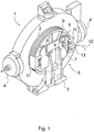
- Fig. 1 presents an oblique top view of a hoisting machine 1 of an elevator with its traction sheave 2.
- the hoisting machine 1 also comprises at least a frame 3, which depending on the model of the elevator is fitted to be fixed e.g. to the floor of the machine room or to the guide rail of the elevator in an elevator without machine room.
- the operating brakes 4 prevent rotational movement of the traction sheave 2.
- a locking apparatus 5 provided with a holding means 6 as presented in more detail in Fig. 3 is fitted in connection with the frame 3, which locking apparatus is arranged to arrest movement of the elevator car by preventing rotation of the traction sheave 2 by means of shape-locking, when e.g.
- the holding means 6 is e.g. a metal rod and it is fixed to its base 7 formed by the frame part of the locking apparatus 5 by means of a hinge 6a. In the case according to Fig. 1 , the holding means 6 is not in the locking position, so the elevator can move freely.
- Fig. 2 presents an oblique top view of a hoisting machine 1 of an elevator according to Fig. 1 , in which the locking apparatus 5 according to the invention is in its locking position.
- the holding means 6 of the locking apparatus 5 is turned around the hinge 6a into its locking position in the groove 8 such that the end of the holding means 6 on the side of the traction sheave 2 extends between the spokes 9 of the traction sheave 2.
- the traction sheave 2 starts to rotate the end of the holding means 6 that is between the spokes 9 hits the spoke 9 that functions as a holding detent, in which case the rotational movement of the traction sheave 2, and simultaneously movement of the elevator car, is prevented.
- Fig. 3 presents a more detailed oblique top view of one locking apparatus 5 according to the invention.
- the locking apparatus 5 comprises an essentially plate-like base 7 that functions as a frame part, which base is e.g. a piece cut into a certain shape from a metal plate.
- the base 7 is provided to be fixed essentially immovably to the frame 3 of the hoisting machine 1.
- the locking apparatus 5 also comprises an essentially rod-like holding means 6, which is hinged to the base 7 by means of a hinge 6a, as has been described above.
- the holding means 6 is hinged on the outer surface of the base 7, i.e. on a fixing lug 14 on the surface that points away from the traction sheave 2, which fixing lug comprises a hole essentially in the direction of the plane of the base for the hinge 6a.
- the holding means 6 is fixed near its first end between the fixing elements 15, which fixing elements 15 press the rod-like part of the holding element 6 tightly between each other. Owing to the viewing angle, only the second fixing means 15 is seen in Fig.
- Both fixing elements 15 comprise a hole, through which the hinge pin 6a can be pushed when installing the holding means 6 into its fixing lug 14.
- the hinge pin 6a of the holding means 6 is locked into its position in the axial direction e.g. by means of cotter pins, nuts or corresponding locking elements.
- the locking apparatus 5 comprises one or more grooves 8, at least on the top edge of the base 7, for the holding means 6, a locking means 10 and also position detector means 13 for the holding means 6.
- jump guards 11 are fixed to both side edges of the base 7, which jump guards do not however actually belong to the locking apparatus 5 itself. The jump guards 11 are arranged to prevent the hoisting ropes from jumping off the traction sheave 2.
- the holding means 6 is fitted to turn around the hinge 6a in the direction of the plane of the base 7 into the groove 8 on the top edge of the base 7 and thus to meet at its end on the traction sheave 2 side the holding detent 9 on the traction sheave 2, such as e.g. a spoke in the radial direction of the traction sheave or a corresponding cast detent.
- the holding means 6 can be activated, i.e. can be turned between the spokes of the traction sheave 2, either by hand or e.g. by remote control.
- the locking means 10 is hinged to its base 7 next to the groove 8.
- the locking means 10 is arranged to turn to close the groove 8 and thus to prevent the holding means 6 from jumping from its locking position out of the groove 8.
- Detector means 13 that detect the position of the holding means are also connected to the holding means 6, which detector means are arranged to give notification when the holding means 6 is in use, so that no attempt is made to drive the elevator when the holding means 6 is between the spokes 9 of the traction sheave 2.
- the detector means 13 are connected to the control system of the elevator e.g. via conductors 12.
- a second groove 8 is also made ready on the opposite side of the base 7 in the lateral direction so that the position of the holding means 6 could, if necessary, be changed or so that also a second holding means could be connected to the base 7.
- the locking apparatus can be fixed to elsewhere in the proximity of the traction sheave than to the hoisting machine itself.
- the holding means can be e.g. a rod or corresponding element that can be directly pushed inwards or pulled outwards. In this case the holding means is moved e.g. backwards and forwards in the axial direction of the traction sheave.
- the detent of the holding means can be something other than a spoke of the traction sheave, such as e.g. a detent made separately to the traction sheave.
- This type of detent can also be separate from the traction sheave, e.g. on the brake rim that rotates along with the traction sheave, on the rotor rim that rotates the traction sheave or on similar to it.
- An easy way to make a number of detents that are separate from the traction sheave is to connect a flange or ring, comprising teeth or holes, to the traction sheave.
Landscapes
- Engineering & Computer Science (AREA)
- Mechanical Engineering (AREA)
- Civil Engineering (AREA)
- Structural Engineering (AREA)
- Cage And Drive Apparatuses For Elevators (AREA)
Description
- The object of the present invention is an elevator provided with locking apparatus to prevent movement of the elevator car as presented in the preamble of
claim 1 and a locking apparatus to prevent movement of the elevator car as presented in the preamble ofclaim 4. - In some situations, e.g. when installing an elevator or when the hoisting machine or the brakes of an elevator are being serviced, tested or adjusted, movement of the elevator car and of the counterweight must be prevented in some other way than by means of the operating brakes. It is known that this can be performed by locking the elevator car and/or the counterweight into their positions on the guide rail e.g. by means of a safety gear, a latch or wedges. This is, however, awkward, laborious and time-consuming, and necessitates working in the elevator hoistway. Another prior-art solution is to fix a rope clamp to the hoisting roping, by means of which the hoisting roping is bound fast to e.g. the overhead beam of the hoistway. This is also, however, an awkward and time-consuming solution and requires special tools.
- The
US 5,202,539 discloses an elevator brake for a traction sheave, wherein a locking means activates a brake star which brake star hos brake surfaces with the traction sheave to brake the traction sheave. Via this device the braking torque of the braking action can be increased compared to the common operating brake of the traction sheave drive. - The purpose of this invention is to eliminate the aforementioned drawbacks and to achieve an elevator provided with locking apparatus to prevent movement of the elevator car as well as an operationally reliable, easy to use, simple and inexpensive locking apparatus to prevent movement of the elevator car. The elevator according to the invention is characterized by what is disclosed in the characterization part of
claim 1. Correspondingly, the locking apparatus according to the invention is characterized by what is disclosed in the characterization part ofclaim 6. Other embodiments of the invention are characterized by what is disclosed in the other claims. - Some inventive embodiments are also discussed in the descriptive section of the present application. The inventive content may also consist of several separate inventions, especially if the invention is considered in the light of expressions or implicit sub-tasks or from the point of view of advantages or categories of advantages achieved. In this case, some of the attributes contained in the claims below may be superfluous from the point of view of separate inventive concepts. Likewise the different details presented in connection with each embodiment can also be applied in other embodiments. In addition it can be stated that at least some of the subordinate claims can in at least some situations be deemed to be inventive in their own right.
- The basic idea of the invention is to prevent unintended movement of the elevator car in servicing work, in connection with installation or in a corresponding situation by acting on the traction sheave. According to the invention, prevention is performed with a separate holding means, of which there can be one or more for each direction of rotation of the traction sheave or instead shared for both directions of rotation. Preferably one holding means is arranged to act on the traction sheave. The balancing in traction sheave elevators is often such that in a normal servicing situation unintended movement can occur in only one direction, in which case the only holding means can be suitably arranged to prevent movement in only this direction. A highly suitable solution is also one in which there is one dedicated holding means for each direction of rotation. Preferably the holding means is a prevention apparatus resting on the frame of the machine, which
prevention apparatus can be brought, if necessary, to meet the detent on the traction sheave and thus to prevent rotation of the traction sheave. The holding apparatus can if necessary be made in connection with the brake incorporated in the machine. Functionally the holding apparatus is independent of the brake, whether it is in connection with the brake or separate from the brake. One advantage of the solution according to the invention is that by means of it movement of the elevator car and of the counterweight can be effectively, dependably and safely prevented. Another advantage is that the arrangement is very easy and quick to use, nor does it necessitate awkward working in the hoistway. A further advantage is that the apparatus according to the invention is disposed in connection with the hoisting machine, in which case it is easy to access it when the hoisting machine or the brakes are being serviced. An advantage of the positioning of the apparatus is also that long trailing cables for the electrical monitoring of its space are not needed, because it is disposed near the control system of the elevator. Another advantage is that the apparatus can be used with different car heights. Yet another advantage is that the apparatus is suited for many different elevators and hoisting machines. Another advantage is also that the apparatus is easy to install and it is particularly suited to the modernization of a very old elevator, even if e.g. the car sling and the guide rails were made by different manufacturers. Another advantage is that the apparatus takes little space. A particularly suitable application for the invention is in connection with the machines of gearless elevators. A further advantage is that the solution is inexpensive and simple to implement. - In the following, the invention will be described in greater detail by referring to an embodiment example and the attached simplified drawings, wherein
- Fig. 1
- presents an oblique top view of a hoisting machine of an elevator, in which a locking apparatus according to the invention is used, which locking apparatus is not in the locking position in the figure,
- Fig. 2
- presents an oblique top view of a hoisting machine of an elevator, in which a locking apparatus according to the invention is used, which locking apparatus is in the locking position in the figure, and
- Fig. 3
- presents an oblique top view of one locking apparatus according to the invention when detached.
-
Fig. 1 presents an oblique top view of a hoistingmachine 1 of an elevator with itstraction sheave 2. The hoistingmachine 1 also comprises at least aframe 3, which depending on the model of the elevator is fitted to be fixed e.g. to the floor of the machine room or to the guide rail of the elevator in an elevator without machine room. In a normal situation, when the elevator is not driving, theoperating brakes 4 prevent rotational movement of thetraction sheave 2. According to the invention, alocking apparatus 5 provided with aholding means 6 as presented in more detail inFig. 3 is fitted in connection with theframe 3, which locking apparatus is arranged to arrest movement of the elevator car by preventing rotation of thetraction sheave 2 by means of shape-locking, when e.g. the hoistingmachine 1 or thebrakes 4 are being serviced or when thebrakes 4 are disconnected for some other reason. Theholding means 6 is e.g. a metal rod and it is fixed to itsbase 7 formed by the frame part of thelocking apparatus 5 by means of ahinge 6a. In the case according toFig. 1 , the holding means 6 is not in the locking position, so the elevator can move freely. -
Fig. 2 presents an oblique top view of a hoistingmachine 1 of an elevator according toFig. 1 , in which thelocking apparatus 5 according to the invention is in its locking position. In this case the holding means 6 of thelocking apparatus 5 is turned around thehinge 6a into its locking position in thegroove 8 such that the end of the holding means 6 on the side of thetraction sheave 2 extends between thespokes 9 of thetraction sheave 2. When thetraction sheave 2 starts to rotate the end of theholding means 6 that is between thespokes 9 hits thespoke 9 that functions as a holding detent, in which case the rotational movement of thetraction sheave 2, and simultaneously movement of the elevator car, is prevented. -
Fig. 3 presents a more detailed oblique top view of onelocking apparatus 5 according to the invention. Thelocking apparatus 5 comprises an essentially plate-like base 7 that functions as a frame part, which base is e.g. a piece cut into a certain shape from a metal plate. Thebase 7 is provided to be fixed essentially immovably to theframe 3 of the hoistingmachine 1. - The
locking apparatus 5 also comprises an essentially rod-like holding means 6, which is hinged to thebase 7 by means of ahinge 6a, as has been described above. Theholding means 6 is hinged on the outer surface of thebase 7, i.e. on afixing lug 14 on the surface that points away from thetraction sheave 2, which fixing lug comprises a hole essentially in the direction of the plane of the base for thehinge 6a. Suitably there are twofixing lugs 14, and inFig. 3 for the sake of clarity only thefree fixing lug 14 is numbered. Theholding means 6 is fixed near its first end between thefixing elements 15, which fixingelements 15 press the rod-like part of theholding element 6 tightly between each other. Owing to the viewing angle, only the second fixing means 15 is seen inFig. 3 . Bothfixing elements 15 comprise a hole, through which thehinge pin 6a can be pushed when installing the holding means 6 into itsfixing lug 14. Thehinge pin 6a of theholding means 6 is locked into its position in the axial direction e.g. by means of cotter pins, nuts or corresponding locking elements. - In addition, the
locking apparatus 5 comprises one ormore grooves 8, at least on the top edge of thebase 7, for theholding means 6, a locking means 10 and also position detector means 13 for theholding means 6. In addition,jump guards 11 are fixed to both side edges of thebase 7, which jump guards do not however actually belong to thelocking apparatus 5 itself. Thejump guards 11 are arranged to prevent the hoisting ropes from jumping off thetraction sheave 2. - For preventing movement of the elevator car and rotational movement of the
traction sheave 2, the holding means 6 is fitted to turn around thehinge 6a in the direction of the plane of thebase 7 into thegroove 8 on the top edge of thebase 7 and thus to meet at its end on thetraction sheave 2 side theholding detent 9 on thetraction sheave 2, such as e.g. a spoke in the radial direction of the traction sheave or a corresponding cast detent. The holding means 6 can be activated, i.e. can be turned between the spokes of thetraction sheave 2, either by hand or e.g. by remote control. - The locking means 10 is hinged to its
base 7 next to thegroove 8. The locking means 10 is arranged to turn to close thegroove 8 and thus to prevent the holding means 6 from jumping from its locking position out of thegroove 8. Detector means 13 that detect the position of the holding means are also connected to the holding means 6, which detector means are arranged to give notification when the holding means 6 is in use, so that no attempt is made to drive the elevator when the holding means 6 is between thespokes 9 of thetraction sheave 2. The detector means 13 are connected to the control system of the elevator e.g. viaconductors 12. Asecond groove 8 is also made ready on the opposite side of thebase 7 in the lateral direction so that the position of the holding means 6 could, if necessary, be changed or so that also a second holding means could be connected to thebase 7. - It is obvious to the person skilled in the art that different embodiments of the invention are not limited to the example described above, but that they may be varied within the scope of the claims presented below. Thus, for example, the solution according to the invention can be used in a different type of hoisting machine than that described above.
- It is also obvious to the person skilled in the art that the locking apparatus can be fixed to elsewhere in the proximity of the traction sheave than to the hoisting machine itself.
- Likewise it is obvious to the person skilled in the art that the locking apparatus and holding means according to the invention can be different to what is described above. The holding means can be e.g. a rod or corresponding element that can be directly pushed inwards or pulled outwards. In this case the holding means is moved e.g. backwards and forwards in the axial direction of the traction sheave.
- It is further obvious to the person skilled in the art that the detent of the holding means can be something other than a spoke of the traction sheave, such as e.g. a detent made separately to the traction sheave. This type of detent can also be separate from the traction sheave, e.g. on the brake rim that rotates along with the traction sheave, on the rotor rim that rotates the traction sheave or on similar to it. There can be a number of detents. An easy way to make a number of detents that are separate from the traction sheave is to connect a flange or ring, comprising teeth or holes, to the traction sheave.
- It is further obvious to the person skilled in the art that there can be e.g. two holding means instead of one, of which e.g. one can lock the traction sheave in one direction of rotation and the other can lock the traction sheave in the other direction of rotation.
Claims (10)
- Elevator provided with locking apparatus (5) to prevent movement of the elevator car, which elevator comprises at least a hoisting machine (1) provided with a traction sheave (2), a frame (3) and at least one brake (4), which locking apparatus (5) comprises a holding means (6) for preventing rotational movement of the traction sheave (2), wherein the holding means (6) is fitted to meet the holding detent (9) on the traction sheave (2),
whereby the holding means (6) is hinged to the locking apparatus (5) by means of a hinge (6a) and arranged to turn around the hinge (6a) into its locking position against the holding detent (9) to prevent rotational movement of the traction sheave (2). - Elevator according to claim 1, characterized in that the locking apparatus (5) is fixed in connection with the hoisting machine (1) of the elevator.
- Elevator according to claim 1 or 2, characterized in that the flank of the traction sheave comprises one or more holding detents (9), and in that the holding means (6) is arranged to rest against the holding detent (9) to prevent rotational movement of the traction sheave (2).
- Locking apparatus to prevent movement of the elevator car, which locking apparatus (5) comprises a base (7) formed by the frame part (3) of the hoisting machine and a holding means (6) for preventing movement of the elevator car, which locking apparatus (5) is disposed with respect to the hoisting machine (1) such that the holding means (6) of the locking apparatus (5) is arranged to prevent rotational movement of the traction sheave (2) by means of shape-locking, wherein the holding means (6) is fitted to meet the holding detent (9) on the traction sheave (2), whereby the holding means (6) is arranged to meet the holding detent (9) on the traction sheave (2) by turning around a hinge (6a).
- Locking apparatus according to claim 4, characterized in that the base (7) of the locking apparatus is fixed to the frame (3) of the hoisting machine (1).
- Locking apparatus according to claim 4 or 5, characterized in that the holding means (6) is arranged to meet the holding detent (9) on the traction sheave (2).
- Locking apparatus according to claim 4, 5 or 6, characterized in that the holding means (6) is fixed to its base (7) on the frame (3) by means of a hinge (6a).
- Locking apparatus according to any of claims 4 - 7 above, characterized in that the base (7) comprises a groove (8), into which the holding means (6) is arranged to turn in the locking phase of the traction sheave (2).
- Locking apparatus according to any of claims 4 - 8, characterized in that the base (7) comprises a locking means (10), which is arranged to prevent the exit of the holding means (6) from the groove (8).
- Locking apparatus according to any of claims 4 - 9 above, characterized in that detector means (13) are connected to the holding means (6) for detecting the locking position of the holding means (6).
Applications Claiming Priority (2)
| Application Number | Priority Date | Filing Date | Title |
|---|---|---|---|
| FI20090010A FI125327B (en) | 2009-01-12 | 2009-01-12 | Elevator with the lift basket movement preventing locking device and the lift basket movement preventing locking device |
| PCT/FI2010/000002 WO2010079259A1 (en) | 2009-01-12 | 2010-01-12 | Elevator provided with locking apparatus to prevent movement of the elevator car and locking apparatus to prevent movement of the elevator car |
Publications (3)
| Publication Number | Publication Date |
|---|---|
| EP2376360A1 EP2376360A1 (en) | 2011-10-19 |
| EP2376360A4 EP2376360A4 (en) | 2014-07-23 |
| EP2376360B1 true EP2376360B1 (en) | 2017-07-12 |
Family
ID=40329440
Family Applications (1)
| Application Number | Title | Priority Date | Filing Date |
|---|---|---|---|
| EP10729122.1A Not-in-force EP2376360B1 (en) | 2009-01-12 | 2010-01-12 | Elevator provided with locking apparatus to prevent movement of the elevator car and locking apparatus to prevent movement of the elevator car |
Country Status (5)
| Country | Link |
|---|---|
| US (1) | US9751726B2 (en) |
| EP (1) | EP2376360B1 (en) |
| CN (1) | CN102272030B (en) |
| FI (1) | FI125327B (en) |
| WO (1) | WO2010079259A1 (en) |
Families Citing this family (8)
| Publication number | Priority date | Publication date | Assignee | Title |
|---|---|---|---|---|
| CN102774773A (en) * | 2012-08-06 | 2012-11-14 | 吴江信谊精密五金有限公司 | Brake device for traction sheave of elevator |
| CN102774772A (en) * | 2012-08-06 | 2012-11-14 | 吴江信谊精密五金有限公司 | Brake device for traction sheave of elevator |
| CN102774776B (en) * | 2012-08-06 | 2014-10-29 | 吴江信谊精密五金有限公司 | Brake latch hook for elevator traction sheave |
| CN102774771B (en) * | 2012-08-06 | 2014-10-29 | 吴江信谊精密五金有限公司 | Electromagnetic control traction sheave brake |
| CN103183266A (en) * | 2013-03-18 | 2013-07-03 | 苏州富士电梯有限公司 | Speed limiter tension device for elevator |
| CN104401834B (en) * | 2014-11-21 | 2016-08-17 | 申龙电梯股份有限公司 | Elevator traction machine band-type brake force checking device and method |
| CN115298128B (en) * | 2020-04-10 | 2025-11-28 | 三菱电机株式会社 | Auxiliary brake of passenger conveyor |
| CN112938722B (en) * | 2021-02-19 | 2022-09-20 | 山东易龙电梯有限公司 | Portal frame elevator overhauls safety pin structure |
Family Cites Families (18)
| Publication number | Priority date | Publication date | Assignee | Title |
|---|---|---|---|---|
| DE3406633A1 (en) * | 1983-03-09 | 1984-09-20 | Bongers & Deimann, 4000 Düsseldorf | Device for limiting the descent of a lift |
| CH680356A5 (en) * | 1989-09-15 | 1992-08-14 | Rudolf Frei Mechanische Werkst | Rotary lock for motorcycle or bicycle - has locking bolt blocking vehicle wheel and internal bolt for lock cylinder released via key |
| US5133201A (en) * | 1991-01-28 | 1992-07-28 | Lamott Darryl L | Vehicle wheel locking assembly |
| US5202539A (en) * | 1991-08-28 | 1993-04-13 | Inventio Ag | Emergency brake apparatus for an elevator |
| JP2726586B2 (en) | 1991-11-28 | 1998-03-11 | 株式会社東芝 | Elevator hoist |
| US5517837A (en) * | 1993-08-12 | 1996-05-21 | Wang; Teng-Cheng | Disc brake locking assembly |
| CA2166841C (en) | 1995-01-31 | 2006-08-22 | Heinrich Foelix | Temporary working space protection |
| JP2000191250A (en) * | 1998-12-25 | 2000-07-11 | Mitsubishi Electric Corp | Elevator hoist equipment |
| CN2427398Y (en) * | 2000-05-26 | 2001-04-25 | 李吉源 | Disc brake lock |
| JP4170295B2 (en) * | 2002-12-04 | 2008-10-22 | 三菱電機株式会社 | Elevator braking device |
| US7104367B2 (en) * | 2003-05-30 | 2006-09-12 | Warner Electric Europe S.A.S. | Modular and adaptable brake system for an elevator sheave |
| US6966409B2 (en) * | 2003-09-09 | 2005-11-22 | Jiun Jyh Wang | Backup power device for elevator |
| WO2006018884A1 (en) | 2004-08-19 | 2006-02-23 | Mitsubishi Denki Kabushiki Kaisha | Brake device for elevator |
| JP2006200604A (en) * | 2005-01-19 | 2006-08-03 | Mitsubishi Electric Corp | Rotating body stationary holding device |
| DE102005022897A1 (en) * | 2005-05-18 | 2006-11-23 | Chr. Mayr Gmbh + Co Kg | Mounting brake for traction sheave |
| US20080041127A1 (en) * | 2005-07-29 | 2008-02-21 | New Hampton Technologies, Llc | Vehicle Lock |
| US7392885B2 (en) * | 2006-08-14 | 2008-07-01 | Chiu Nan Wang | Emergency escape apparatus for elevator |
| TWI391160B (en) * | 2009-02-26 | 2013-04-01 | Rexon Ind Corp Ltd | Safety device for elliptical exercise machines |
-
2009
- 2009-01-12 FI FI20090010A patent/FI125327B/en active IP Right Grant
-
2010
- 2010-01-12 WO PCT/FI2010/000002 patent/WO2010079259A1/en not_active Ceased
- 2010-01-12 EP EP10729122.1A patent/EP2376360B1/en not_active Not-in-force
- 2010-01-12 CN CN201080004206.1A patent/CN102272030B/en not_active Expired - Fee Related
-
2011
- 2011-07-01 US US13/175,095 patent/US9751726B2/en not_active Expired - Fee Related
Non-Patent Citations (1)
| Title |
|---|
| None * |
Also Published As
| Publication number | Publication date |
|---|---|
| CN102272030B (en) | 2014-11-26 |
| CN102272030A (en) | 2011-12-07 |
| EP2376360A4 (en) | 2014-07-23 |
| EP2376360A1 (en) | 2011-10-19 |
| FI125327B (en) | 2015-08-31 |
| FI20090010L (en) | 2010-07-13 |
| WO2010079259A1 (en) | 2010-07-15 |
| US20110290592A1 (en) | 2011-12-01 |
| FI20090010A0 (en) | 2009-01-12 |
| US9751726B2 (en) | 2017-09-05 |
Similar Documents
| Publication | Publication Date | Title |
|---|---|---|
| US9751726B2 (en) | Locking apparatus to prevent movement of an elevator car | |
| EP2016015B1 (en) | Method for installing the hoisting roping of an elevator | |
| JP4722855B2 (en) | Elevator equipment | |
| US9862569B2 (en) | Brake and an elevator | |
| EP3283425B1 (en) | Elevator system | |
| EA016364B1 (en) | Arrangement in the supply of rope to the speed limiter | |
| KR20080092376A (en) | Elevator and elevator brake | |
| EP1717474B1 (en) | Brake device and hoist for elevator | |
| EP3656725B1 (en) | Fail safe bar for clutch type brake adjustment | |
| JP6336224B1 (en) | Elevator equipment | |
| CN1110441C (en) | Elevator with speed limiter | |
| CN112010139B (en) | Rope anti-drop device for elevator tractor | |
| JPWO2002053485A1 (en) | Elevator emergency braking system | |
| JP4387243B2 (en) | Elevator confinement rescue device | |
| JP6293078B2 (en) | Elevator equipment | |
| CN112499441A (en) | Machine room-less elevator transformation method and machine room-less elevator | |
| EP4729457A1 (en) | Car lock device and elevator system | |
| CN119858848A (en) | Traction machines and elevators | |
| JP2010037042A (en) | Elevator driving device | |
| JP2008265901A (en) | Elevator safety device | |
| JP2008024480A (en) | Man conveyor emergency braking system | |
| JP2025028539A (en) | Elevator Equipment | |
| JP2013112502A (en) | Elevator thin hoisting machine | |
| JP2011016603A (en) | Hoisting machine for elevator | |
| HK1133865A1 (en) | Elevator apparatus |
Legal Events
| Date | Code | Title | Description |
|---|---|---|---|
| PUAI | Public reference made under article 153(3) epc to a published international application that has entered the european phase |
Free format text: ORIGINAL CODE: 0009012 |
|
| 17P | Request for examination filed |
Effective date: 20110701 |
|
| AK | Designated contracting states |
Kind code of ref document: A1 Designated state(s): AT BE BG CH CY CZ DE DK EE ES FI FR GB GR HR HU IE IS IT LI LT LU LV MC MK MT NL NO PL PT RO SE SI SK SM TR |
|
| DAX | Request for extension of the european patent (deleted) | ||
| A4 | Supplementary search report drawn up and despatched |
Effective date: 20140623 |
|
| RIC1 | Information provided on ipc code assigned before grant |
Ipc: B66D 5/34 20060101ALI20140616BHEP Ipc: B66B 5/00 20060101AFI20140616BHEP Ipc: B66B 11/04 20060101ALI20140616BHEP |
|
| GRAP | Despatch of communication of intention to grant a patent |
Free format text: ORIGINAL CODE: EPIDOSNIGR1 |
|
| STAA | Information on the status of an ep patent application or granted ep patent |
Free format text: STATUS: GRANT OF PATENT IS INTENDED |
|
| INTG | Intention to grant announced |
Effective date: 20170214 |
|
| GRAS | Grant fee paid |
Free format text: ORIGINAL CODE: EPIDOSNIGR3 |
|
| GRAA | (expected) grant |
Free format text: ORIGINAL CODE: 0009210 |
|
| STAA | Information on the status of an ep patent application or granted ep patent |
Free format text: STATUS: THE PATENT HAS BEEN GRANTED |
|
| RIN1 | Information on inventor provided before grant (corrected) |
Inventor name: AHONIEMI, JARMO Inventor name: MALIN, MARKO Inventor name: KETONEN, ARI |
|
| AK | Designated contracting states |
Kind code of ref document: B1 Designated state(s): AT BE BG CH CY CZ DE DK EE ES FI FR GB GR HR HU IE IS IT LI LT LU LV MC MK MT NL NO PL PT RO SE SI SK SM TR |
|
| REG | Reference to a national code |
Ref country code: GB Ref legal event code: FG4D |
|
| REG | Reference to a national code |
Ref country code: CH Ref legal event code: EP |
|
| REG | Reference to a national code |
Ref country code: AT Ref legal event code: REF Ref document number: 908122 Country of ref document: AT Kind code of ref document: T Effective date: 20170715 |
|
| REG | Reference to a national code |
Ref country code: IE Ref legal event code: FG4D |
|
| REG | Reference to a national code |
Ref country code: DE Ref legal event code: R096 Ref document number: 602010043563 Country of ref document: DE |
|
| REG | Reference to a national code |
Ref country code: NL Ref legal event code: MP Effective date: 20170712 |
|
| REG | Reference to a national code |
Ref country code: LT Ref legal event code: MG4D |
|
| REG | Reference to a national code |
Ref country code: AT Ref legal event code: MK05 Ref document number: 908122 Country of ref document: AT Kind code of ref document: T Effective date: 20170712 |
|
| REG | Reference to a national code |
Ref country code: FR Ref legal event code: PLFP Year of fee payment: 9 |
|
| PG25 | Lapsed in a contracting state [announced via postgrant information from national office to epo] |
Ref country code: LT Free format text: LAPSE BECAUSE OF FAILURE TO SUBMIT A TRANSLATION OF THE DESCRIPTION OR TO PAY THE FEE WITHIN THE PRESCRIBED TIME-LIMIT Effective date: 20170712 Ref country code: FI Free format text: LAPSE BECAUSE OF FAILURE TO SUBMIT A TRANSLATION OF THE DESCRIPTION OR TO PAY THE FEE WITHIN THE PRESCRIBED TIME-LIMIT Effective date: 20170712 Ref country code: HR Free format text: LAPSE BECAUSE OF FAILURE TO SUBMIT A TRANSLATION OF THE DESCRIPTION OR TO PAY THE FEE WITHIN THE PRESCRIBED TIME-LIMIT Effective date: 20170712 Ref country code: SE Free format text: LAPSE BECAUSE OF FAILURE TO SUBMIT A TRANSLATION OF THE DESCRIPTION OR TO PAY THE FEE WITHIN THE PRESCRIBED TIME-LIMIT Effective date: 20170712 Ref country code: AT Free format text: LAPSE BECAUSE OF FAILURE TO SUBMIT A TRANSLATION OF THE DESCRIPTION OR TO PAY THE FEE WITHIN THE PRESCRIBED TIME-LIMIT Effective date: 20170712 Ref country code: NO Free format text: LAPSE BECAUSE OF FAILURE TO SUBMIT A TRANSLATION OF THE DESCRIPTION OR TO PAY THE FEE WITHIN THE PRESCRIBED TIME-LIMIT Effective date: 20171012 Ref country code: NL Free format text: LAPSE BECAUSE OF FAILURE TO SUBMIT A TRANSLATION OF THE DESCRIPTION OR TO PAY THE FEE WITHIN THE PRESCRIBED TIME-LIMIT Effective date: 20170712 |
|
| PG25 | Lapsed in a contracting state [announced via postgrant information from national office to epo] |
Ref country code: ES Free format text: LAPSE BECAUSE OF FAILURE TO SUBMIT A TRANSLATION OF THE DESCRIPTION OR TO PAY THE FEE WITHIN THE PRESCRIBED TIME-LIMIT Effective date: 20170712 Ref country code: BG Free format text: LAPSE BECAUSE OF FAILURE TO SUBMIT A TRANSLATION OF THE DESCRIPTION OR TO PAY THE FEE WITHIN THE PRESCRIBED TIME-LIMIT Effective date: 20171012 Ref country code: IS Free format text: LAPSE BECAUSE OF FAILURE TO SUBMIT A TRANSLATION OF THE DESCRIPTION OR TO PAY THE FEE WITHIN THE PRESCRIBED TIME-LIMIT Effective date: 20171112 Ref country code: PL Free format text: LAPSE BECAUSE OF FAILURE TO SUBMIT A TRANSLATION OF THE DESCRIPTION OR TO PAY THE FEE WITHIN THE PRESCRIBED TIME-LIMIT Effective date: 20170712 Ref country code: GR Free format text: LAPSE BECAUSE OF FAILURE TO SUBMIT A TRANSLATION OF THE DESCRIPTION OR TO PAY THE FEE WITHIN THE PRESCRIBED TIME-LIMIT Effective date: 20171013 Ref country code: LV Free format text: LAPSE BECAUSE OF FAILURE TO SUBMIT A TRANSLATION OF THE DESCRIPTION OR TO PAY THE FEE WITHIN THE PRESCRIBED TIME-LIMIT Effective date: 20170712 |
|
| REG | Reference to a national code |
Ref country code: DE Ref legal event code: R097 Ref document number: 602010043563 Country of ref document: DE |
|
| PG25 | Lapsed in a contracting state [announced via postgrant information from national office to epo] |
Ref country code: RO Free format text: LAPSE BECAUSE OF FAILURE TO SUBMIT A TRANSLATION OF THE DESCRIPTION OR TO PAY THE FEE WITHIN THE PRESCRIBED TIME-LIMIT Effective date: 20170712 Ref country code: DK Free format text: LAPSE BECAUSE OF FAILURE TO SUBMIT A TRANSLATION OF THE DESCRIPTION OR TO PAY THE FEE WITHIN THE PRESCRIBED TIME-LIMIT Effective date: 20170712 Ref country code: CZ Free format text: LAPSE BECAUSE OF FAILURE TO SUBMIT A TRANSLATION OF THE DESCRIPTION OR TO PAY THE FEE WITHIN THE PRESCRIBED TIME-LIMIT Effective date: 20170712 |
|
| PLBE | No opposition filed within time limit |
Free format text: ORIGINAL CODE: 0009261 |
|
| STAA | Information on the status of an ep patent application or granted ep patent |
Free format text: STATUS: NO OPPOSITION FILED WITHIN TIME LIMIT |
|
| PG25 | Lapsed in a contracting state [announced via postgrant information from national office to epo] |
Ref country code: SK Free format text: LAPSE BECAUSE OF FAILURE TO SUBMIT A TRANSLATION OF THE DESCRIPTION OR TO PAY THE FEE WITHIN THE PRESCRIBED TIME-LIMIT Effective date: 20170712 Ref country code: SM Free format text: LAPSE BECAUSE OF FAILURE TO SUBMIT A TRANSLATION OF THE DESCRIPTION OR TO PAY THE FEE WITHIN THE PRESCRIBED TIME-LIMIT Effective date: 20170712 Ref country code: EE Free format text: LAPSE BECAUSE OF FAILURE TO SUBMIT A TRANSLATION OF THE DESCRIPTION OR TO PAY THE FEE WITHIN THE PRESCRIBED TIME-LIMIT Effective date: 20170712 Ref country code: IT Free format text: LAPSE BECAUSE OF FAILURE TO SUBMIT A TRANSLATION OF THE DESCRIPTION OR TO PAY THE FEE WITHIN THE PRESCRIBED TIME-LIMIT Effective date: 20170712 |
|
| 26N | No opposition filed |
Effective date: 20180413 |
|
| PG25 | Lapsed in a contracting state [announced via postgrant information from national office to epo] |
Ref country code: SI Free format text: LAPSE BECAUSE OF FAILURE TO SUBMIT A TRANSLATION OF THE DESCRIPTION OR TO PAY THE FEE WITHIN THE PRESCRIBED TIME-LIMIT Effective date: 20170712 |
|
| REG | Reference to a national code |
Ref country code: CH Ref legal event code: PL |
|
| PG25 | Lapsed in a contracting state [announced via postgrant information from national office to epo] |
Ref country code: LU Free format text: LAPSE BECAUSE OF NON-PAYMENT OF DUE FEES Effective date: 20180112 |
|
| REG | Reference to a national code |
Ref country code: IE Ref legal event code: MM4A |
|
| REG | Reference to a national code |
Ref country code: BE Ref legal event code: MM Effective date: 20180131 |
|
| PG25 | Lapsed in a contracting state [announced via postgrant information from national office to epo] |
Ref country code: LI Free format text: LAPSE BECAUSE OF NON-PAYMENT OF DUE FEES Effective date: 20180131 Ref country code: CH Free format text: LAPSE BECAUSE OF NON-PAYMENT OF DUE FEES Effective date: 20180131 Ref country code: BE Free format text: LAPSE BECAUSE OF NON-PAYMENT OF DUE FEES Effective date: 20180131 |
|
| PG25 | Lapsed in a contracting state [announced via postgrant information from national office to epo] |
Ref country code: IE Free format text: LAPSE BECAUSE OF NON-PAYMENT OF DUE FEES Effective date: 20180112 |
|
| PG25 | Lapsed in a contracting state [announced via postgrant information from national office to epo] |
Ref country code: MC Free format text: LAPSE BECAUSE OF FAILURE TO SUBMIT A TRANSLATION OF THE DESCRIPTION OR TO PAY THE FEE WITHIN THE PRESCRIBED TIME-LIMIT Effective date: 20170712 |
|
| PG25 | Lapsed in a contracting state [announced via postgrant information from national office to epo] |
Ref country code: MT Free format text: LAPSE BECAUSE OF NON-PAYMENT OF DUE FEES Effective date: 20180112 |
|
| PG25 | Lapsed in a contracting state [announced via postgrant information from national office to epo] |
Ref country code: TR Free format text: LAPSE BECAUSE OF FAILURE TO SUBMIT A TRANSLATION OF THE DESCRIPTION OR TO PAY THE FEE WITHIN THE PRESCRIBED TIME-LIMIT Effective date: 20170712 |
|
| PG25 | Lapsed in a contracting state [announced via postgrant information from national office to epo] |
Ref country code: HU Free format text: LAPSE BECAUSE OF FAILURE TO SUBMIT A TRANSLATION OF THE DESCRIPTION OR TO PAY THE FEE WITHIN THE PRESCRIBED TIME-LIMIT; INVALID AB INITIO Effective date: 20100112 Ref country code: PT Free format text: LAPSE BECAUSE OF FAILURE TO SUBMIT A TRANSLATION OF THE DESCRIPTION OR TO PAY THE FEE WITHIN THE PRESCRIBED TIME-LIMIT Effective date: 20170712 |
|
| PG25 | Lapsed in a contracting state [announced via postgrant information from national office to epo] |
Ref country code: CY Free format text: LAPSE BECAUSE OF FAILURE TO SUBMIT A TRANSLATION OF THE DESCRIPTION OR TO PAY THE FEE WITHIN THE PRESCRIBED TIME-LIMIT Effective date: 20170712 Ref country code: MK Free format text: LAPSE BECAUSE OF NON-PAYMENT OF DUE FEES Effective date: 20170712 |
|
| PGFP | Annual fee paid to national office [announced via postgrant information from national office to epo] |
Ref country code: GB Payment date: 20220119 Year of fee payment: 13 Ref country code: DE Payment date: 20220119 Year of fee payment: 13 |
|
| PGFP | Annual fee paid to national office [announced via postgrant information from national office to epo] |
Ref country code: FR Payment date: 20220119 Year of fee payment: 13 |
|
| REG | Reference to a national code |
Ref country code: DE Ref legal event code: R119 Ref document number: 602010043563 Country of ref document: DE |
|
| GBPC | Gb: european patent ceased through non-payment of renewal fee |
Effective date: 20230112 |
|
| PG25 | Lapsed in a contracting state [announced via postgrant information from national office to epo] |
Ref country code: GB Free format text: LAPSE BECAUSE OF NON-PAYMENT OF DUE FEES Effective date: 20230112 Ref country code: DE Free format text: LAPSE BECAUSE OF NON-PAYMENT OF DUE FEES Effective date: 20230801 |
|
| PG25 | Lapsed in a contracting state [announced via postgrant information from national office to epo] |
Ref country code: FR Free format text: LAPSE BECAUSE OF NON-PAYMENT OF DUE FEES Effective date: 20230131 |