EP2375870A2 - Light control method and system - Google Patents
Light control method and system Download PDFInfo
- Publication number
- EP2375870A2 EP2375870A2 EP11161310A EP11161310A EP2375870A2 EP 2375870 A2 EP2375870 A2 EP 2375870A2 EP 11161310 A EP11161310 A EP 11161310A EP 11161310 A EP11161310 A EP 11161310A EP 2375870 A2 EP2375870 A2 EP 2375870A2
- Authority
- EP
- European Patent Office
- Prior art keywords
- color
- illumination
- luminaire
- daylight
- light
- Prior art date
- Legal status (The legal status is an assumption and is not a legal conclusion. Google has not performed a legal analysis and makes no representation as to the accuracy of the status listed.)
- Granted
Links
Images

Classifications
-
- H—ELECTRICITY
- H05—ELECTRIC TECHNIQUES NOT OTHERWISE PROVIDED FOR
- H05B—ELECTRIC HEATING; ELECTRIC LIGHT SOURCES NOT OTHERWISE PROVIDED FOR; CIRCUIT ARRANGEMENTS FOR ELECTRIC LIGHT SOURCES, IN GENERAL
- H05B45/00—Circuit arrangements for operating light-emitting diodes [LED]
- H05B45/20—Controlling the colour of the light
- H05B45/22—Controlling the colour of the light using optical feedback
-
- H—ELECTRICITY
- H05—ELECTRIC TECHNIQUES NOT OTHERWISE PROVIDED FOR
- H05B—ELECTRIC HEATING; ELECTRIC LIGHT SOURCES NOT OTHERWISE PROVIDED FOR; CIRCUIT ARRANGEMENTS FOR ELECTRIC LIGHT SOURCES, IN GENERAL
- H05B45/00—Circuit arrangements for operating light-emitting diodes [LED]
- H05B45/20—Controlling the colour of the light
- H05B45/24—Controlling the colour of the light using electrical feedback from LEDs or from LED modules
Definitions
- the present invention relates to a method for controlling at least one light source for achieving illumination with a desired color or color temperature. Furthermore, the present invention relates to a corresponding light control system for carrying out the method according to the invention.
- a certain area for example, the surface of a table or a wall area appear in a particular color or with a desired color temperature
- the ultimately resulting illumination in the area does not depend solely on the used and controllable light source but also influenced by other factors.
- the influence of the daylight entering through the window is relatively large and can lead to the illumination ultimately resulting in the area deviating significantly in terms of its color or color temperature from the light emitted by the light source or lamp. So it is Corrective actions required to take into account the influence of daylight.
- the present invention is therefore based on the object to provide a novel way to control the light output of a lamp, in which a lighting with a desired color or color temperature is achieved in a fast and reliable manner in a range, the above-described transient response is largely suppressed ,
- the inventive method is characterized by the fact that no control is carried out in the classical sense but instead suitable control values for the luminaire are calculated.
- suitable control values for the luminaire are calculated.
- the influence of the natural daylight is first calculated and, based on this, a suitable control value for the luminaire is calculated and transmitted to it.
- the current actual value of the illumination is again first determined. Based on this, however, supplementary information is taken into account in order to determine a suitable light output by calculation. As a result, the previously described transient response can be suppressed.
- the intensity and the color of the light emitted by the light can be calculated, for example, on the basis of the current control value of the light. This information is immediately available and can therefore be taken into account appropriately.
- the above-mentioned steps can be repeated again. In this case, a correction would then be made in a further step. Theoretically, these cycles could be repeated in any number. However, after one or two cycles, as a rule, the resulting illumination will deviate only insignificantly from the specified target value.
- the influence of daylight is taken into account by emitting a light corresponding to a color locus which differs from the desired color locus.
- By mixing between daylight and artificial light ultimately results in a lighting that corresponds to the desired color location.
- the light output of the light source has to be modified with regard to the color of the daylight.
- the problem may now arise that not at the same time lighting with the desired color and desired intensity can be obtained.
- this will be the intensity of the illumination since the brightness is usually more relevant than the color.
- the inventive method is not limited to a single light source but can of course be extended to a variety of light sources.
- FIG. 1 Shown is a room 100 in which a table 105 is located with a work surface 106.
- An illumination of the room 100 and in particular of the work surface 106 is carried out with the help of arranged on the ceiling of the room 100 lights 107-109, which are variable in terms of their light output. In particular, there is the possibility of intensity and to change the color of the emitted light.
- the control of the three lights 107-109 takes place via a control unit 110.
- the working surface 106 of the table 105 is also influenced by the natural daylight, which can enter the room 100 through a window 101.
- a blind 102 At the window 101 is a blind 102, over which the influence of daylight can be reduced.
- complete suppression of daylight is often undesirable.
- control unit 110 must adjust the light output of the lights 107-109 such that the resulting mixed light consisting of the artificial light and the outside light has the desired color location. This is done in the context of the method according to the invention, which will be described in more detail below.
- the light control system has a sensor 120, which is arranged, for example, on the ceiling of the room 100.
- the position of the sensor 120 may also be changed, but substantially, the sensor 120 is capable of determining the intensity and color location of the illumination present on the table surface 106. This information is transmitted from the sensor 120 to the control unit 110.
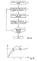
- FIG. 3a shows the sequence of the method according to the invention.
- FIG. 3b shows the resulting adjustment of the illumination to the desired color location compared to a classic scheme.
- the vertical axis characterizes a color parameter of the light.
- the color of the light output is determined only by a single parameter. In the present case, it could be, for example, the color temperature.
- the illumination has a color temperature T.
- the inventive method consists of several individual steps, which in FIG. 3a are shown and explained below.
- a first step 10 the current color location of the illumination present on the table surface 106 is first determined with the aid of the sensor 120.
- step 11 the intensity and the color location of the light emitted by the lights are determined. This can be done on the basis of the known current control values for the lights, which allow a conclusion on the emitted light.
- control unit 110 Based on the information obtained in steps 10 and 11, the influence of natural daylight is then calculated in step 12.
- the control unit 110 thus, what is the proportion of daylight.
- the color location of the daylight is determined.
- control values for the luminaires are then calculated in a further step 13, which arithmetically suitable for causing illumination of a table surface 106 when the artificial light is mixed with the daylight, which corresponds to the desired value T with respect to its color temperature. These control values are then transmitted to the luminaires.
- FIG. 3b The result of this procedure can FIG. 3b be removed.
- the set values to the lamp at the time t 1 In contrast to the continuous adjustment in the frame of the scheme is to be transmitted the set values to the lamp at the time t 1, so that directly receive a light with the color temperature value T. 1 Ideally, this already largely corresponds to the desired value T.
- step 14 Due to thermal changes of the light sources or aging phenomena, however, the case may arise that the resulting color temperature value T 1 deviates from the desired value T. This will be checked in step 14. Should it be determined that the deviation exceeds a predetermined limit, steps 11-13 are repeated (the current color actual value is already known due to the check in step 14). At the time T 2 , in turn, new control values are transferred to the lights, and the optimized color temperature value T 2 now results. This cycle could be repeated many times. Usually, however, it will already be after or Two steps result in a lighting that corresponds largely to the desired lighting. If, therefore, it is determined in step 14 that the resulting illumination within a predetermined limit has the desired color temperature value, the method is ended.
- the artificial light is selected in a targeted manner such that it compensates the influence of daylight in a suitable manner.
- the problem may arise that to compensate for the daylight, an artificial light is required, which indeed leads to the desired color, but ultimately leads to illumination with insufficient brightness.
- the intensity of the illumination is preferably higher Prioritized and then adjusted the color as much as possible.
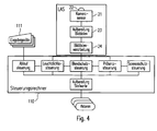
- a control system will be explained schematically, which is preferably used for carrying out the method according to the invention.
- This brings advantages in particular when several areas of the room are to be illuminated in different ways. Basically, this would require several individual sensors that record and evaluate the respective area.
- the system according to FIG. 4 is characterized by the fact that in turn only a single sensor unit is used.
- This provided with the reference numeral 120 sensor unit comprises an imaging digital sensor 21 with associated optics 22, means for processing the image data 23 and in particular a unit 24, which analyzes the image data and generates based on control information, which provides information about the intensity and the individual areas Color of the present lighting included.
- individual sections of the sensor 21, which may be formed for example by an RGB CCD sensor, detected, analyzed and evaluated. These respective areas would be the Areas correspond, which would have to be monitored by small sensors when using classical sensors.
- the information captured by the sensor unit 120 is then transmitted to the control unit 110, which takes into account this information in the manner described above and generates the control values for the lamps based thereon. Desired setpoint values for the illumination can be input via corresponding operating devices or input devices 111, which are coupled to the control unit 110.
Abstract
Description
Die vorliegende Erfindung betrifft ein Verfahren zum Steuern mindestens einer Lichtquelle zum Erzielen einer Beleuchtung mit einer gewünschten Farbe bzw. Farbtemperatur. Ferner betrifft die vorliegende Erfindung ein entsprechendes Lichtsteuersystem zur Durchführung des erfindungsgemäßen Verfahrens.The present invention relates to a method for controlling at least one light source for achieving illumination with a desired color or color temperature. Furthermore, the present invention relates to a corresponding light control system for carrying out the method according to the invention.
Die fortschreitende Entwicklung von Lichtquellen führt dazu, dass immer mehr Möglichkeiten bestehen, die Beleuchtung eines Bereichs oder einer Fläche in verschiedenster Art und Weise zu beeinflussen. Während früher in erster Linie eine Veränderung der Helligkeit durchgeführt wurde, besteht nunmehr auch die Möglichkeit, Einfluss auf die Farbe der Beleuchtung zu nehmen. Möglich wurde dies zunächst durch die Verwendung von entsprechenden Farbfiltern, welche den Lichtquellen zugeordnet waren. Mittlerweile werden allerdings immer öfter LEDs als Lichtquellen verwendet, welche eine deutlich komfortablere Beeinflussung der Farbabgabe ermöglichen. Es sind zwischenzeitlich LEDs in den verschiedensten Farben erhältlich, wobei die Möglichkeit besteht, durch die Kombination unterschiedlicher Farben Licht nahezu eines jeden beliebigen Farbtons zu erzielen. Insbesondere sogenannte RGB-Lichtquellen kommen zum Einsatz, bei denen die LEDs Licht in den Farben Rot, Grün und Blau emittieren. Darüber hinaus wird oftmals zusätzlich als weitere Grundfarbe auch noch Gelb verwendet, da hierdurch insbesondere die Erzeugung sogenannten Weißlichts, also von Licht, das für einen Betrachter als weiß empfunden wird, optimiert werden kann.The progressive development of light sources means that more and more possibilities exist for influencing the illumination of a region or a surface in various ways. While in the past, a change in brightness was primarily carried out, it is now also possible to influence the color of the lighting. This was made possible by the use of appropriate color filters, which were assigned to the light sources. Meanwhile, however, LEDs are increasingly used as light sources, which allow a much more comfortable influencing the color output. Meanwhile, LEDs are available in a wide range of colors, with the possibility of achieving almost any color by combining different colors of light. In particular, so-called RGB light sources are used, in which the LEDs emit light in the colors red, green and blue. In addition, yellow is often used in addition as a further base color, as this in particular the generation of so-called white light, that is, light that is perceived as white for a viewer, can be optimized.
Soll nunmehr ein bestimmter Bereich, beispielsweise die Oberfläche eines Tischs oder ein Wandbereich in einem bestimmten Farbton bzw. mit einer gewünschten Farbtemperatur erscheinen, so ist zu berücksichtigen, dass die letztendlich resultierende Beleuchtung in dem Bereich nicht ausschließlich von der verwendeten und ansteuerbaren Lichtquelle abhängt sondern auch durch andere Faktoren beeinflusst wird. Insbesondere der Einfluss des durch Fenster eintretenden Tageslichts ist verhältnismäßig groß und kann dazu führen, dass die in dem Bereich letztendlich resultierende Beleuchtung hinsichtlich ihrer Farbe oder ihrer Farbtemperatur deutlich von dem von der Lichtquelle bzw. Leuchte abgegebenen Licht abweicht. Es sind also Korrekturmaßnahmen erforderlich, mit denen der Einfluss des Tageslichts berücksichtigt werden kann.If now a certain area, for example, the surface of a table or a wall area appear in a particular color or with a desired color temperature, it should be noted that the ultimately resulting illumination in the area does not depend solely on the used and controllable light source but also influenced by other factors. In particular, the influence of the daylight entering through the window is relatively large and can lead to the illumination ultimately resulting in the area deviating significantly in terms of its color or color temperature from the light emitted by the light source or lamp. So it is Corrective actions required to take into account the influence of daylight.
Denkbar wäre in diesem Zusammenhang, einen Sensor auf den zu beleuchtenden Bereich zu richten und hierdurch den tatsächlich vorliegenden Farbton zu bestimmen. Diese Information kann dann an eine Steuereinheit übermittelt werden, welche im Sinne einer Regelung die Lichtabgabe der Leuchte solange verändert, bis letztendlich der gewünschte Farbton bzw. die gewünschte Farbtemperatur erhalten wird.It would be conceivable in this context to direct a sensor to the area to be illuminated and thereby determine the color actually present. This information can then be transmitted to a control unit, which changes the light output of the lamp in the sense of a regulation until finally the desired color or the desired color temperature is obtained.
Nachteilig an dieser Vorgehensweise ist allerdings, dass derartige Regelungsverfahren zu einem Einschwingverhalten führen, welches dazu führt, dass vor Erreichen des gewünschten Farbtons zunächst starke Veränderungen stattfinden. Diese werden oftmals als störend empfunden und sollten dementsprechend vermieden werden.A disadvantage of this approach, however, is that such control methods lead to a transient response, which leads to the fact that before reaching the desired hue first strong changes take place. These are often perceived as disturbing and should be avoided accordingly.
Der vorliegenden Erfindung liegt dementsprechend die Aufgabe zu Grunde, eine neuartige Möglichkeit zum Steuern der Lichtabgabe einer Leuchte anzugeben, bei der in schneller und zuverlässiger Weise in einem Bereich eine Beleuchtung mit einer gewünschten Farbe oder Farbtemperatur erzielt wird, wobei das oben geschilderte Einschwingverhalten weitestgehend unterdrückt wird.The present invention is therefore based on the object to provide a novel way to control the light output of a lamp, in which a lighting with a desired color or color temperature is achieved in a fast and reliable manner in a range, the above-described transient response is largely suppressed ,
Die Aufgabe wird durch ein Verfahren mit den Merkmalen des Anspruchs 1 sowie durch ein Lichtsteuersystem gemäß Anspruch 7 gelöst. Vorteilhafte Weiterbildungen der Erfindung sind Gegenstand der abhängigen Ansprüche.The object is achieved by a method having the features of claim 1 and by a light control system according to claim 7. Advantageous developments of the invention are the subject of the dependent claims.
Das erfindungsgemäße Verfahren zeichnet sich dadurch aus, dass keine Regelung im klassischen Sinne durchgeführt wird sondern stattdessen geeignete Stellwerte für die Leuchte berechnet werden. Hierbei wird zunächst der Einfluss des natürlichen Tageslichts berechnet und darauf basierend dann ein geeigneter Stellwert für die Leuchte berechnet und an diese übermittelt.The inventive method is characterized by the fact that no control is carried out in the classical sense but instead suitable control values for the luminaire are calculated. In this case, the influence of the natural daylight is first calculated and, based on this, a suitable control value for the luminaire is calculated and transmitted to it.
Erfindungsgemäß wird also ein Verfahren zum Steuern mindestens einer Leuchte zum Erzielen einer Beleuchtung mit einer gewünschten Farbe oder Farbtemperatur vorgeschlagen, welches die folgenden Schritte aufweist:
- a) Ermitteln des aktuellen Farborts einer in einem zu beleuchtenden Bereich vorliegenden Beleuchtung;
- b) Ermitteln der Intensität und des Farborts des von der Leuchte abgegebenen Lichts;
- c) Berechnen des Einflusses des natürlichen Tageslichts;
- d) Berechnen und Übermitteln eines Stellwerts für die Leuchte, wobei der Stellwert dazu geeignet ist, bei Mischung des von der Leuchte abgegebenen Lichts mit dem Tageslicht eine Beleuchtung mit einer Farbtemperatur zu erzielen, die im Wesentlichen einem vorgegebenen Sollwert entspricht.
- a) determining the current color location of a present in an area to be illuminated lighting;
- b) determining the intensity and color location of the light emitted by the luminaire;
- c) calculating the influence of natural daylight;
- d) calculating and transmitting a control value for the luminaire, wherein the manipulated variable is suitable for achieving illumination with a color temperature which substantially corresponds to a predetermined desired value when the light emitted by the luminaire is combined with the daylight.
Zu Beginn des erfindungsgemäßen Verfahrens wird also wiederum zunächst der aktuelle Istwert der Beleuchtung ermittelt. Darauf basierend werden allerdings dann ergänzende Informationen berücksichtigt, um eine geeignete Lichtabgabe rechnerisch zu bestimmen. Hierdurch kann das zuvor geschilderte Einschwingverhalten unterdrückt werden.At the beginning of the method according to the invention, therefore, the current actual value of the illumination is again first determined. Based on this, however, supplementary information is taken into account in order to determine a suitable light output by calculation. As a result, the previously described transient response can be suppressed.
Die Intensität und die Farbe des von der Leuchte abgegebenen Lichts kann beispielsweise auf Basis des aktuellen Stellwerts der Leuchte berechnet werden. Diese Informationen stehen unmittelbar zur Verfügung und können dementsprechend in geeigneter Weise berücksichtigt werden.The intensity and the color of the light emitted by the light can be calculated, for example, on the basis of the current control value of the light. This information is immediately available and can therefore be taken into account appropriately.
Sollte die Abweichung der resultierenden Beleuchtung von dem gewünschten Farbort eine vorgegebene Grenze überschreiten, können die oben genannten Schritte nochmals wiederholt werden. In diesem Fall würde dann also in einem weiteren Schritt eine Nachkorrektur vorgenommen werden. Theoretisch könnten diese Zyklen in beliebiger Anzahl wiederholt werden. Allerdings wird nach ein oder zwei Zyklen in der Regel die resultierende Beleuchtung nur noch unwesentlich von dem vorgegebenen Sollwert abweichen.If the deviation of the resulting illumination from the desired color location exceeds a predetermined limit, the above-mentioned steps can be repeated again. In this case, a correction would then be made in a further step. Theoretically, these cycles could be repeated in any number. However, after one or two cycles, as a rule, the resulting illumination will deviate only insignificantly from the specified target value.
Grundsätzlich wird der Einfluss des Tageslichts dadurch berücksichtigt, dass die Leuchte ein Licht entsprechend einem Farbort abgegeben wird, welcher von dem gewünschten Farbort abweicht. Durch die Vermischung zwischen Tageslicht und künstlichem Licht allerdings ergibt sich dann letztendlich eine Beleuchtung, die dem gewünschten Farbort entspricht. Es muss also die Lichtabgabe der Lichtquelle im Hinblick auf die Farbe des Tageslichts modifiziert werden. Hierbei kann sich nunmehr das Problem ergeben, dass nicht gleichzeitig eine Beleuchtung mit gewünschter Farbe und gewünschter Intensität erhalten werden kann. In diesem Fall besteht die Möglichkeit, einem der beiden Parameter eine erhöhte Priorität zuzuweisen. Üblicherweise wird dies die Intensität der Beleuchtung sein, da die Helligkeit in der Regel eine größere Relevanz besitzt als die Farbe. Alternativ hierzu würde allerdings auch die Möglichkeit bestehen, in einem derartigen Fall den Einfluss des Tageslichts zumindest teilweise zu reduzieren, was beispielsweise durch den Einsatz von Jalousien oder dergleichen erfolgen kann.In principle, the influence of daylight is taken into account by emitting a light corresponding to a color locus which differs from the desired color locus. By mixing between daylight and artificial light, however, ultimately results in a lighting that corresponds to the desired color location. So the light output of the light source has to be modified with regard to the color of the daylight. Here, the problem may now arise that not at the same time lighting with the desired color and desired intensity can be obtained. In this case it is possible to assign an increased priority to one of the two parameters. Usually, this will be the intensity of the illumination since the brightness is usually more relevant than the color. Alternatively, however, would also be possible to reduce the influence of daylight in such a case, at least partially, which can be done for example by the use of blinds or the like.
Das erfindungsgemäße Verfahren ist nicht auf eine einzige Lichtquelle beschränkt sondern kann selbstverständlich auf eine Vielzahl von Lichtquellen ausgeweitet werden.The inventive method is not limited to a single light source but can of course be extended to a variety of light sources.
Ferner wird erfindungsgemäß ein Lichtsteuersystem zum Erzielen einer Beleuchtung mit einer gewünschten Farbtemperatur vorgeschlagen, welches aufweist:
- eine Leuchte, deren Lichtabgabe hinsichtlich der Intensität und des Farborts veränderbar ist;
- Sensormittel zum Erfassen des aktuellen Farborts einer in einem zu beleuchtenden Bereich vorliegenden Beleuchtung und
- eine Steuereinheit, welche dazu ausgebildet ist, die Intensität und den Farbort des von der Leuchte abgegebenen Lichts zu bestimmen, darauf basierend den Einfluss des natürlichen Tageslichts zu berechnen und einen Stellwert für die Leuchte zu berechnen und zu übermitteln, wobei der Stellwert dazu geeignet ist, bei der Mischung des von der Leuchte abgegebenen Lichts mit dem Tageslicht eine Beleuchtung mit einer Farbtemperatur zu erzielen, die im Wesentlichen einem vorgegebenen Sollwert entspricht.
- a lamp whose light output is changeable with respect to the intensity and the color location;
- Sensor means for detecting the current color locus of existing in an area to be illuminated lighting and
- a control unit which is designed to determine the intensity and the color location of the light emitted by the luminaire, to calculate thereon the influence of the natural daylight and to calculate and transmit a control value for the luminaire, the control value being suitable to achieve, with the mixing of the light emitted by the luminaire with the daylight, illumination with a color temperature which substantially corresponds to a predetermined desired value.
Nachfolgend soll die Erfindung anhand der beiliegenden Zeichnung näher erläutert werden. Es zeigen:
- Figuren 1 und 2
- schematisch die Ansichten eines Raums, bei dem das erfindungsgemäße Steuerungskonzept zum Einsatz kommen soll;
- Figur 3a
- den Ablauf des erfindungsgemäßen Verfahrens;
- Figur 3b
- ein Schema zur Verdeutlichung der Vorgehensweise bei der erfindungsgemäßen Lichtsteuerung und
- Figur 4
- ein zur Realisierung des erfindungsgemäßen Verfahrens bevorzugt eingesetztes Lichtsteuersystem.
- Figures 1 and 2
- schematically the views of a room in which the control concept according to the invention is to be used;
- FIG. 3a
- the course of the method according to the invention;
- FIG. 3b
- a scheme for illustrating the procedure in the light control according to the invention and
- FIG. 4
- a preferably used for the realization of the method according to the invention light control system.
Anhand der
Neben dem Licht der Leuchten 107-109 wird die Arbeitsfläche 106 des Tischs 105 allerdings auch durch das natürliche Tageslicht beeinflusst, welches durch ein Fenster 101 in den Raum 100 einfallen kann. An dem Fenster 101 befindet sich eine Jalousie 102, über welche der Einfluss des Tageslichts reduziert werden kann. Eine vollständige Unterdrückung des Tageslichts ist allerdings oftmals nicht gewünscht.In addition to the light of the lamps 107-109, however, the working
Soll nun die Oberfläche 106 des Tischs 105 in einer bestimmten Farbe oder Farbtemperatur erscheinen, so muss die Steuereinheit 110 die Lichtabgabe der Leuchten 107-109 derart einstellen, dass das resultierende Mischlicht bestehend aus dem künstlichen Licht und dem Außenlicht den gewünschten Farbort aufweist. Dies erfolgt im Rahmen des erfindungsgemäßen Verfahrens, welches nachfolgend näher beschrieben werden soll.Now, if the
Voraussetzung des Verfahrens ist, dass Informationen über die aktuell an der Tischoberfläche 106 vorliegenden Beleuchtungsbedingungen erhalten werden. Hierfür weist das Lichtsteuersystem einen Sensor 120 auf, der beispielsweise an der Decke des Raums 100 angeordnet ist. Die Position des Sensors 120 kann auch verändert werden, wesentlich allerdings ist, dass der Sensor 120 in der Lage ist, die Intensität und den Farbort der an der Tischoberfläche 106 vorliegenden Beleuchtung zu bestimmen. Diese Informationen werden von dem Sensor 120 an die Steuereinheit 110 übermittelt.The prerequisite of the method is that information about the lighting conditions currently present on the
Der Ablauf des erfindungsgemäßen Verfahrens ist schematisch in
Würde zum Einstellen des Kunstlichts eine klassische Regelung vorgenommen werden, so würde sich für die resultierende Beleuchtung ein Farbverlauf ergeben, welcher der Kurve II entspricht. Erkennbar ist, dass hier die Regelung zunächst zu einer schnellen Anpassung der Farbtemperatur führt, allerdings zunächst die gewünschte Farbtemperatur T überschritten wird, was weitere Korrekturen erfordert, die letztendlich zu dem angedeuteten Einschwingverhalten führen. Die Farbe der Beleuchtung wird in diesem Fall also während des Anpassens periodisch verändert, was als unangenehm empfunden wird. Mit dem erfindungsgemäßen Verfahren wird dies verhindert.If a classical regulation were to be made for adjusting the artificial light, a color progression would result for the resulting illumination which corresponds to the curve II. It can be seen that the regulation initially leads to a rapid adjustment of the color temperature, but first the desired color temperature T is exceeded, which requires further corrections, which ultimately lead to the indicated transient response. The color of the illumination is changed periodically in this case during fitting, which is perceived as unpleasant. This is prevented by the method according to the invention.
Das erfindungsgemäße Verfahren besteht aus mehreren einzelnen Schritten, die in
Basierend auf den in den Schritten 10 und 11 erhaltenen Informationen wird dann in Schritt 12 der Einfluss des natürlichen Tageslichts berechnet. Die Steuereinheit 110 also, wie hoch der Anteil des Tageslichts ist. Insbesondere wird auch der Farbort des Tageslichts bestimmt. Darauf basierend werden dann in einem weiteren Schritt 13 Stellwerte für die Leuchten berechnet, welche rechnerisch dazu geeignet sind, bei Mischung des Kunstlichts mit dem Tageslicht eine Beleuchtung einer Tischoberfläche 106 hervorzurufen, welche hinsichtlich ihrer Farbtemperatur dem gewünschten Wert T entspricht. Diese Stellwerte werden dann an die Leuchten übermittelt.Based on the information obtained in
Das Ergebnis dieser Vorgehensweise kann
Aufgrund von thermischen Veränderungen der Lichtquellen oder Alterungserscheinungen kann allerdings der Fall auftreten, dass der resultierende Farbtemperaturwert T1 von dem gewünschten Wert T abweicht. Dies wird in Schritt 14 überprüft. Sollte hierbei festgestellt werden, dass die Abweichung eine vorgegebene Grenze überschreitet, so werden die Schritte 11-13 wiederholt (der aktuelle Farb-Istwert ist aufgrund der Kontrolle in Schritt 14 ohnehin bereits bekannt). Zum Zeitpunkt T2 werden dann wiederum neue Stellwerte an die Leuchten übergeben und es ergibt sich nunmehr der optimierte Farbtemperaturwert T2. Dieser Zyklus könnte des Öfteren wiederholt werden. In der Regel wird sich allerdings bereits nach ein oder zwei Schritten eine Beleuchtung ergeben, die weitestgehend der gewünschten Beleuchtung entspricht. Wird also in Schritt 14 festgestellt, dass die daraus resultierende Beleuchtung innerhalb einer vorgegebenen Grenze den gewünschten Farbtemperaturwert aufweist, so wird das Verfahren beendet.Due to thermal changes of the light sources or aging phenomena, however, the case may arise that the resulting color temperature value T 1 deviates from the desired value T. This will be checked in
Ein Vergleich zu Kurve II im Falle einer klassischen Regelung zeigt unmittelbar, dass bei einem erfindungsgemäßen Verfahren kein störendes Einschwingverhalten der Beleuchtung erfolgt. Die Anpassung der Beleuchtung erfolgt deutlich effektiver und schneller. Wesentlich hierbei ist, dass die geeigneten Stellwerte gezielt berechnet werden, wobei hierfür die zuvor erhaltenen ergänzenden Informationen berücksichtigt werden. Das vorliegende Beispiel wurde anhand der Anpassung der Farbtemperatur geschildert. Selbstverständlich ist das Verfahren allerdings nicht auf eine Farbtemperaturanpassung beschränkt sondern kann grundsätzlich eingesetzt werden, wenn eine Beleuchtung mit einem bestimmten Farbton, also auch außerhalb des Weißlichtbereichs erzielt werden soll.A comparison to curve II in the case of a classical control directly shows that no disturbing transient response of the illumination occurs in a method according to the invention. The adaptation of the lighting is much more effective and faster. It is essential here that the appropriate control values are calculated in a targeted manner, taking into account the previously obtained supplementary information for this purpose. The present example was described by the adjustment of the color temperature. Of course, the method is, however, not limited to a color temperature adjustment but can be used in principle, if an illumination with a certain hue, so also outside the white light area to be achieved.
Im Zuge des Verfahrens wird also das Kunstlicht in gezielter Weise derart gewählt, dass es den Einfluss des Tageslichts in geeigneter Weise ausgleicht. Es kann sich hierbei nun das Problem ergeben, dass zum Ausgleichen des Tageslichts ein Kunstlicht erforderlich ist, welches zwar zu der gewünschten Farbe führt, allerdings letztendlich zu einer Beleuchtung mit einer unzureichenden Helligkeit führt, In einem derartigen Fall wird bevorzugt der Intensität der Beleuchtung eine höhere Priorität eingeräumt und dann die Farbe so gut wie möglich angepasst. Denkbar wäre allerdings auch, den Einfluss des Tageslichts durch die Ansteuerung der Jalousie zu reduzieren.In the course of the process, therefore, the artificial light is selected in a targeted manner such that it compensates the influence of daylight in a suitable manner. In this case, the problem may arise that to compensate for the daylight, an artificial light is required, which indeed leads to the desired color, but ultimately leads to illumination with insufficient brightness. In such a case, the intensity of the illumination is preferably higher Prioritized and then adjusted the color as much as possible. However, it would also be conceivable to reduce the influence of daylight by controlling the blind.
Abschließend soll schematisch ein Steuersystem erläutert werden, welches zur Durchführung des erfindungsgemäßen Verfahrens bevorzugt zum Einsatz kommt. Dieses bringt insbesondere dann Vorteile mit sich, wenn mehrere Bereiche des Raums in unterschiedlicher Weise beleuchtet werden sollen. Grundsätzlich wären hierfür mehrere einzelne Sensoren erforderlich, die den jeweiligen Bereich erfassen und bewerten. Das System gemäß
Die von der Sensoreinheit120 erfassten Informationen werden dann an die Steuereinheit 110 übermittelt, welche diese Informationen in der oben beschriebenen Weise berücksichtigt und darauf basierend die Stellwerte für die Leuchten generiert. Gewünschte Sollwerte für die Beleuchtung können über entsprechende Bedieneinrichtungen bzw. Eingabegeräte 111, die mit der Steuereinheit 110 gekoppelt sind, eingegeben werden.The information captured by the
Claims (7)
dadurch gekennzeichnet,
dass die Intensität und der Farbort des von der Leuchte (107, 108, 109) abgegebenen Lichts auf Basis des aktuellen Stellwerts der Leuchte (107, 108, 109) berechnet werden.Method according to claim 1,
characterized,
that the intensity and the color point of the lamp (107, 108, 109) emitting light on the basis of the current control value of the lamp (107, 108, 109) are calculated.
dadurch gekennzeichnet,
dass das Verfahren wiederholt wird, falls die Abweichung der Farbtemperatur der sich ergebenden Beleuchtung von dem Sollwert einen vorgegebenen Grenzwert überschreitet.Method according to claim 1 or 2,
characterized,
that the process is repeated if the deviation of the color temperature of the resulting illumination from the target value exceeds a predetermined limit.
dadurch gekennzeichnet,
dass beim Berechnen des Stellwerts eine für den Bereich vorgesehene Gesamthelligkeit der Beleuchtung Priorität genießt.Method according to one of the preceding claims,
characterized,
in that, when calculating the manipulated variable, priority is given to a total brightness of the illumination intended for the area.
dadurch gekennzeichnet,
dass der Einfluss des Tageslichts durch die Aktivierung von Blendschutz- oder Abschattungseinrichtungen, insbesondere Jalousien, zumindest teilweise reduziert wird.Method according to one of the preceding claims,
characterized,
that the influence of daylight is at least partially reduced by the activation of anti-glare or shading devices, in particular blinds.
dadurch gekennzeichnet,
dass Stellwerte für mehrere Leuchte (107, 108, 109) berechnet werden.Method according to one of the preceding claims,
characterized,
that control values for several luminaires (107, 108, 109) are calculated.
Applications Claiming Priority (1)
| Application Number | Priority Date | Filing Date | Title |
|---|---|---|---|
| DE102010003802A DE102010003802A1 (en) | 2010-04-09 | 2010-04-09 | Method and system for lighting control |
Publications (3)
| Publication Number | Publication Date |
|---|---|
| EP2375870A2 true EP2375870A2 (en) | 2011-10-12 |
| EP2375870A3 EP2375870A3 (en) | 2014-06-18 |
| EP2375870B1 EP2375870B1 (en) | 2017-03-01 |
Family
ID=44486136
Family Applications (1)
| Application Number | Title | Priority Date | Filing Date |
|---|---|---|---|
| EP11161310.5A Active EP2375870B1 (en) | 2010-04-09 | 2011-04-06 | Light control method and system |
Country Status (3)
| Country | Link |
|---|---|
| EP (1) | EP2375870B1 (en) |
| DE (1) | DE102010003802A1 (en) |
| PL (1) | PL2375870T3 (en) |
Cited By (1)
| Publication number | Priority date | Publication date | Assignee | Title |
|---|---|---|---|---|
| GB2547643A (en) * | 2016-02-29 | 2017-08-30 | Ping Lai Chung | Modeling illumination device |
Families Citing this family (1)
| Publication number | Priority date | Publication date | Assignee | Title |
|---|---|---|---|---|
| DE102011081097A1 (en) * | 2011-08-17 | 2013-02-21 | Siemens Aktiengesellschaft | Method for controlling and regulating a lighting system |
Family Cites Families (6)
| Publication number | Priority date | Publication date | Assignee | Title |
|---|---|---|---|---|
| WO1996028956A1 (en) * | 1995-03-10 | 1996-09-19 | Philips Electronics N.V. | Lighting system for controlling the colour temperature of artificial light under the influence of the daylight level |
| AT412825B (en) * | 2001-05-16 | 2005-07-25 | Siemens Ag Oesterreich | METHOD FOR REGULATING THE LIGHT RATIO IN A FIELD LIGHTED BY A LIGHT SOURCE CHANGED IN THEIR COLOR TEMPERATURE |
| KR100969907B1 (en) * | 2006-02-23 | 2010-07-13 | 파나소닉 전공 주식회사 | Led luminaire |
| CN101485234B (en) * | 2006-06-28 | 2012-08-08 | 皇家飞利浦电子股份有限公司 | Method of controlling a lighting system based on a target light distribution |
| WO2009034515A2 (en) * | 2007-09-11 | 2009-03-19 | Philips Intellectual Property & Standards Gmbh | Ambient light compensation sensor and procedure |
| US7595786B2 (en) * | 2007-11-13 | 2009-09-29 | Capella Microsystems, Corp. | Illumination system and illumination control method for adaptively adjusting color temperature |
-
2010
- 2010-04-09 DE DE102010003802A patent/DE102010003802A1/en not_active Withdrawn
-
2011
- 2011-04-06 EP EP11161310.5A patent/EP2375870B1/en active Active
- 2011-04-06 PL PL11161310T patent/PL2375870T3/en unknown
Non-Patent Citations (1)
| Title |
|---|
| None |
Cited By (1)
| Publication number | Priority date | Publication date | Assignee | Title |
|---|---|---|---|---|
| GB2547643A (en) * | 2016-02-29 | 2017-08-30 | Ping Lai Chung | Modeling illumination device |
Also Published As
| Publication number | Publication date |
|---|---|
| PL2375870T3 (en) | 2017-09-29 |
| DE102010003802A1 (en) | 2011-10-13 |
| EP2375870B1 (en) | 2017-03-01 |
| EP2375870A3 (en) | 2014-06-18 |
Similar Documents
| Publication | Publication Date | Title |
|---|---|---|
| EP3061321B1 (en) | Lamp which influences the melanopsin production | |
| EP0807877B2 (en) | System for controlling the brightness of a space | |
| DE102007003345B4 (en) | Light Control System | |
| DE3404085C2 (en) | Switch-off device for switching off excess light sources indoors with a dynamic time delay | |
| EP2005799A1 (en) | Colour temperature and colour location control for a light | |
| EP1886708B1 (en) | Lamp with melatonin protection effect | |
| EP2433472B1 (en) | Method for setting a chromaticity coordinate | |
| DE102006045744A1 (en) | A lamp operating device for operating one or more light sources and method for operating a lamp operating device | |
| DE102016121304A1 (en) | LIGHTING CONTROL DEVICE AND LIGHTING SYSTEM | |
| EP3142464B1 (en) | Lighting system | |
| EP2375870B1 (en) | Light control method and system | |
| DE102016102180A1 (en) | Lighting system, controllers, transducers and lighting methods | |
| EP2475227B1 (en) | Lighting system with multiple lights and device for implementing positioning values | |
| DE102013010512B4 (en) | Arrangement with at least one metameric lighting device and passenger cabin | |
| DE102012013039B4 (en) | Lighting device and method for operating the lighting device in a dimming mode | |
| EP2849536B1 (en) | Control method for a mixed light source and control device for a mixed light source | |
| DE102011122256A1 (en) | Device for controlling a lighting device and method for controlling a lighting device | |
| EP2375871B1 (en) | Light control method and system | |
| EP2779801A2 (en) | Lighting system and method for controlling a lighting system | |
| EP3374687A1 (en) | Led light, and method for influencing the spectral distribution of the led light | |
| DE102016104347A1 (en) | Simplified commissioning concept for controlling actuators of a building installation | |
| DE102015002640A1 (en) | Color matching between different lights | |
| EP3138369B1 (en) | Method for operating a light having a plurality of lighting units which are arranged behind each other | |
| EP4002957A1 (en) | Light for livestock rearing systems | |
| DE102012015969A1 (en) | Lighting device for use as slave lighting device in lighting system of motor car, has control device to switch off all LEDs simultaneously when one of LEDs reaches lower threshold intensity value |
Legal Events
| Date | Code | Title | Description |
|---|---|---|---|
| PUAI | Public reference made under article 153(3) epc to a published international application that has entered the european phase |
Free format text: ORIGINAL CODE: 0009012 |
|
| AK | Designated contracting states |
Kind code of ref document: A2 Designated state(s): AL AT BE BG CH CY CZ DE DK EE ES FI FR GB GR HR HU IE IS IT LI LT LU LV MC MK MT NL NO PL PT RO RS SE SI SK SM TR |
|
| AX | Request for extension of the european patent |
Extension state: BA ME |
|
| REG | Reference to a national code |
Ref country code: DE Ref legal event code: R079 Ref document number: 502011011697 Country of ref document: DE Free format text: PREVIOUS MAIN CLASS: H05B0037020000 Ipc: H05B0033080000 |
|
| PUAL | Search report despatched |
Free format text: ORIGINAL CODE: 0009013 |
|
| AK | Designated contracting states |
Kind code of ref document: A3 Designated state(s): AL AT BE BG CH CY CZ DE DK EE ES FI FR GB GR HR HU IE IS IT LI LT LU LV MC MK MT NL NO PL PT RO RS SE SI SK SM TR |
|
| AX | Request for extension of the european patent |
Extension state: BA ME |
|
| RIC1 | Information provided on ipc code assigned before grant |
Ipc: H05B 33/08 20060101AFI20140513BHEP |
|
| 17P | Request for examination filed |
Effective date: 20141215 |
|
| RBV | Designated contracting states (corrected) |
Designated state(s): AL AT BE BG CH CY CZ DE DK EE ES FI FR GB GR HR HU IE IS IT LI LT LU LV MC MK MT NL NO PL PT RO RS SE SI SK SM TR |
|
| GRAP | Despatch of communication of intention to grant a patent |
Free format text: ORIGINAL CODE: EPIDOSNIGR1 |
|
| INTG | Intention to grant announced |
Effective date: 20161020 |
|
| STAA | Information on the status of an ep patent application or granted ep patent |
Free format text: STATUS: GRANT OF PATENT IS INTENDED |
|
| GRAS | Grant fee paid |
Free format text: ORIGINAL CODE: EPIDOSNIGR3 |
|
| GRAA | (expected) grant |
Free format text: ORIGINAL CODE: 0009210 |
|
| STAA | Information on the status of an ep patent application or granted ep patent |
Free format text: STATUS: THE PATENT HAS BEEN GRANTED |
|
| AK | Designated contracting states |
Kind code of ref document: B1 Designated state(s): AL AT BE BG CH CY CZ DE DK EE ES FI FR GB GR HR HU IE IS IT LI LT LU LV MC MK MT NL NO PL PT RO RS SE SI SK SM TR |
|
| REG | Reference to a national code |
Ref country code: GB Ref legal event code: FG4D Free format text: NOT ENGLISH |
|
| REG | Reference to a national code |
Ref country code: CH Ref legal event code: EP Ref country code: CH Ref legal event code: NV Representative=s name: FELBER AND PARTNER AG, CH Ref country code: AT Ref legal event code: REF Ref document number: 872657 Country of ref document: AT Kind code of ref document: T Effective date: 20170315 |
|
| REG | Reference to a national code |
Ref country code: IE Ref legal event code: FG4D Free format text: LANGUAGE OF EP DOCUMENT: GERMAN |
|
| REG | Reference to a national code |
Ref country code: DE Ref legal event code: R096 Ref document number: 502011011697 Country of ref document: DE |
|
| REG | Reference to a national code |
Ref country code: FR Ref legal event code: PLFP Year of fee payment: 7 |
|
| REG | Reference to a national code |
Ref country code: SE Ref legal event code: TRGR |
|
| REG | Reference to a national code |
Ref country code: NL Ref legal event code: MP Effective date: 20170301 |
|
| REG | Reference to a national code |
Ref country code: LT Ref legal event code: MG4D |
|
| PG25 | Lapsed in a contracting state [announced via postgrant information from national office to epo] |
Ref country code: HR Free format text: LAPSE BECAUSE OF FAILURE TO SUBMIT A TRANSLATION OF THE DESCRIPTION OR TO PAY THE FEE WITHIN THE PRESCRIBED TIME-LIMIT Effective date: 20170301 Ref country code: NO Free format text: LAPSE BECAUSE OF FAILURE TO SUBMIT A TRANSLATION OF THE DESCRIPTION OR TO PAY THE FEE WITHIN THE PRESCRIBED TIME-LIMIT Effective date: 20170601 Ref country code: GR Free format text: LAPSE BECAUSE OF FAILURE TO SUBMIT A TRANSLATION OF THE DESCRIPTION OR TO PAY THE FEE WITHIN THE PRESCRIBED TIME-LIMIT Effective date: 20170602 Ref country code: FI Free format text: LAPSE BECAUSE OF FAILURE TO SUBMIT A TRANSLATION OF THE DESCRIPTION OR TO PAY THE FEE WITHIN THE PRESCRIBED TIME-LIMIT Effective date: 20170301 Ref country code: LT Free format text: LAPSE BECAUSE OF FAILURE TO SUBMIT A TRANSLATION OF THE DESCRIPTION OR TO PAY THE FEE WITHIN THE PRESCRIBED TIME-LIMIT Effective date: 20170301 |
|
| PG25 | Lapsed in a contracting state [announced via postgrant information from national office to epo] |
Ref country code: BG Free format text: LAPSE BECAUSE OF FAILURE TO SUBMIT A TRANSLATION OF THE DESCRIPTION OR TO PAY THE FEE WITHIN THE PRESCRIBED TIME-LIMIT Effective date: 20170601 Ref country code: LV Free format text: LAPSE BECAUSE OF FAILURE TO SUBMIT A TRANSLATION OF THE DESCRIPTION OR TO PAY THE FEE WITHIN THE PRESCRIBED TIME-LIMIT Effective date: 20170301 Ref country code: ES Free format text: LAPSE BECAUSE OF FAILURE TO SUBMIT A TRANSLATION OF THE DESCRIPTION OR TO PAY THE FEE WITHIN THE PRESCRIBED TIME-LIMIT Effective date: 20170301 Ref country code: RS Free format text: LAPSE BECAUSE OF FAILURE TO SUBMIT A TRANSLATION OF THE DESCRIPTION OR TO PAY THE FEE WITHIN THE PRESCRIBED TIME-LIMIT Effective date: 20170301 |
|
| PG25 | Lapsed in a contracting state [announced via postgrant information from national office to epo] |
Ref country code: NL Free format text: LAPSE BECAUSE OF FAILURE TO SUBMIT A TRANSLATION OF THE DESCRIPTION OR TO PAY THE FEE WITHIN THE PRESCRIBED TIME-LIMIT Effective date: 20170301 |
|
| PG25 | Lapsed in a contracting state [announced via postgrant information from national office to epo] |
Ref country code: CZ Free format text: LAPSE BECAUSE OF FAILURE TO SUBMIT A TRANSLATION OF THE DESCRIPTION OR TO PAY THE FEE WITHIN THE PRESCRIBED TIME-LIMIT Effective date: 20170301 Ref country code: SK Free format text: LAPSE BECAUSE OF FAILURE TO SUBMIT A TRANSLATION OF THE DESCRIPTION OR TO PAY THE FEE WITHIN THE PRESCRIBED TIME-LIMIT Effective date: 20170301 Ref country code: RO Free format text: LAPSE BECAUSE OF FAILURE TO SUBMIT A TRANSLATION OF THE DESCRIPTION OR TO PAY THE FEE WITHIN THE PRESCRIBED TIME-LIMIT Effective date: 20170301 Ref country code: EE Free format text: LAPSE BECAUSE OF FAILURE TO SUBMIT A TRANSLATION OF THE DESCRIPTION OR TO PAY THE FEE WITHIN THE PRESCRIBED TIME-LIMIT Effective date: 20170301 Ref country code: IT Free format text: LAPSE BECAUSE OF FAILURE TO SUBMIT A TRANSLATION OF THE DESCRIPTION OR TO PAY THE FEE WITHIN THE PRESCRIBED TIME-LIMIT Effective date: 20170301 |
|
| PG25 | Lapsed in a contracting state [announced via postgrant information from national office to epo] |
Ref country code: SM Free format text: LAPSE BECAUSE OF FAILURE TO SUBMIT A TRANSLATION OF THE DESCRIPTION OR TO PAY THE FEE WITHIN THE PRESCRIBED TIME-LIMIT Effective date: 20170301 Ref country code: IS Free format text: LAPSE BECAUSE OF FAILURE TO SUBMIT A TRANSLATION OF THE DESCRIPTION OR TO PAY THE FEE WITHIN THE PRESCRIBED TIME-LIMIT Effective date: 20170701 Ref country code: PT Free format text: LAPSE BECAUSE OF FAILURE TO SUBMIT A TRANSLATION OF THE DESCRIPTION OR TO PAY THE FEE WITHIN THE PRESCRIBED TIME-LIMIT Effective date: 20170703 |
|
| REG | Reference to a national code |
Ref country code: DE Ref legal event code: R097 Ref document number: 502011011697 Country of ref document: DE |
|
| PLBE | No opposition filed within time limit |
Free format text: ORIGINAL CODE: 0009261 |
|
| STAA | Information on the status of an ep patent application or granted ep patent |
Free format text: STATUS: NO OPPOSITION FILED WITHIN TIME LIMIT |
|
| REG | Reference to a national code |
Ref country code: IE Ref legal event code: MM4A |
|
| PG25 | Lapsed in a contracting state [announced via postgrant information from national office to epo] |
Ref country code: MC Free format text: LAPSE BECAUSE OF FAILURE TO SUBMIT A TRANSLATION OF THE DESCRIPTION OR TO PAY THE FEE WITHIN THE PRESCRIBED TIME-LIMIT Effective date: 20170301 Ref country code: DK Free format text: LAPSE BECAUSE OF FAILURE TO SUBMIT A TRANSLATION OF THE DESCRIPTION OR TO PAY THE FEE WITHIN THE PRESCRIBED TIME-LIMIT Effective date: 20170301 |
|
| 26N | No opposition filed |
Effective date: 20171204 |
|
| PG25 | Lapsed in a contracting state [announced via postgrant information from national office to epo] |
Ref country code: LU Free format text: LAPSE BECAUSE OF NON-PAYMENT OF DUE FEES Effective date: 20170406 Ref country code: SI Free format text: LAPSE BECAUSE OF FAILURE TO SUBMIT A TRANSLATION OF THE DESCRIPTION OR TO PAY THE FEE WITHIN THE PRESCRIBED TIME-LIMIT Effective date: 20170301 |
|
| REG | Reference to a national code |
Ref country code: BE Ref legal event code: MM Effective date: 20170430 |
|
| REG | Reference to a national code |
Ref country code: FR Ref legal event code: PLFP Year of fee payment: 8 |
|
| PG25 | Lapsed in a contracting state [announced via postgrant information from national office to epo] |
Ref country code: IE Free format text: LAPSE BECAUSE OF NON-PAYMENT OF DUE FEES Effective date: 20170406 |
|
| PG25 | Lapsed in a contracting state [announced via postgrant information from national office to epo] |
Ref country code: BE Free format text: LAPSE BECAUSE OF NON-PAYMENT OF DUE FEES Effective date: 20170430 |
|
| PG25 | Lapsed in a contracting state [announced via postgrant information from national office to epo] |
Ref country code: MT Free format text: LAPSE BECAUSE OF FAILURE TO SUBMIT A TRANSLATION OF THE DESCRIPTION OR TO PAY THE FEE WITHIN THE PRESCRIBED TIME-LIMIT Effective date: 20170301 |
|
| PG25 | Lapsed in a contracting state [announced via postgrant information from national office to epo] |
Ref country code: HU Free format text: LAPSE BECAUSE OF FAILURE TO SUBMIT A TRANSLATION OF THE DESCRIPTION OR TO PAY THE FEE WITHIN THE PRESCRIBED TIME-LIMIT; INVALID AB INITIO Effective date: 20110406 |
|
| PG25 | Lapsed in a contracting state [announced via postgrant information from national office to epo] |
Ref country code: CY Free format text: LAPSE BECAUSE OF NON-PAYMENT OF DUE FEES Effective date: 20170301 |
|
| PGFP | Annual fee paid to national office [announced via postgrant information from national office to epo] |
Ref country code: ES Payment date: 20190603 Year of fee payment: 10 |
|
| REG | Reference to a national code |
Ref country code: DE Ref legal event code: R079 Ref document number: 502011011697 Country of ref document: DE Free format text: PREVIOUS MAIN CLASS: H05B0033080000 Ipc: H05B0045000000 |
|
| PG25 | Lapsed in a contracting state [announced via postgrant information from national office to epo] |
Ref country code: MK Free format text: LAPSE BECAUSE OF FAILURE TO SUBMIT A TRANSLATION OF THE DESCRIPTION OR TO PAY THE FEE WITHIN THE PRESCRIBED TIME-LIMIT Effective date: 20170301 |
|
| PG25 | Lapsed in a contracting state [announced via postgrant information from national office to epo] |
Ref country code: TR Free format text: LAPSE BECAUSE OF FAILURE TO SUBMIT A TRANSLATION OF THE DESCRIPTION OR TO PAY THE FEE WITHIN THE PRESCRIBED TIME-LIMIT Effective date: 20170301 |
|
| PGFP | Annual fee paid to national office [announced via postgrant information from national office to epo] |
Ref country code: PL Payment date: 20200330 Year of fee payment: 10 |
|
| PG25 | Lapsed in a contracting state [announced via postgrant information from national office to epo] |
Ref country code: AL Free format text: LAPSE BECAUSE OF FAILURE TO SUBMIT A TRANSLATION OF THE DESCRIPTION OR TO PAY THE FEE WITHIN THE PRESCRIBED TIME-LIMIT Effective date: 20170301 |
|
| PGFP | Annual fee paid to national office [announced via postgrant information from national office to epo] |
Ref country code: SE Payment date: 20200424 Year of fee payment: 10 |
|
| REG | Reference to a national code |
Ref country code: AT Ref legal event code: MM01 Ref document number: 872657 Country of ref document: AT Kind code of ref document: T Effective date: 20200406 |
|
| PG25 | Lapsed in a contracting state [announced via postgrant information from national office to epo] |
Ref country code: AT Free format text: LAPSE BECAUSE OF NON-PAYMENT OF DUE FEES Effective date: 20200406 |
|
| REG | Reference to a national code |
Ref country code: DE Ref legal event code: R084 Ref document number: 502011011697 Country of ref document: DE |
|
| REG | Reference to a national code |
Ref country code: SE Ref legal event code: EUG |
|
| PG25 | Lapsed in a contracting state [announced via postgrant information from national office to epo] |
Ref country code: SE Free format text: LAPSE BECAUSE OF NON-PAYMENT OF DUE FEES Effective date: 20210407 |
|
| PG25 | Lapsed in a contracting state [announced via postgrant information from national office to epo] |
Ref country code: PL Free format text: LAPSE BECAUSE OF NON-PAYMENT OF DUE FEES Effective date: 20210406 |
|
| P01 | Opt-out of the competence of the unified patent court (upc) registered |
Effective date: 20230530 |
|
| PGFP | Annual fee paid to national office [announced via postgrant information from national office to epo] |
Ref country code: FR Payment date: 20230421 Year of fee payment: 13 Ref country code: DE Payment date: 20230427 Year of fee payment: 13 Ref country code: CH Payment date: 20230502 Year of fee payment: 13 |
|
| PGFP | Annual fee paid to national office [announced via postgrant information from national office to epo] |
Ref country code: GB Payment date: 20230418 Year of fee payment: 13 |