EP2375475A1 - Wiederaufladbare Batterie - Google Patents
Wiederaufladbare Batterie Download PDFInfo
- Publication number
- EP2375475A1 EP2375475A1 EP11152639A EP11152639A EP2375475A1 EP 2375475 A1 EP2375475 A1 EP 2375475A1 EP 11152639 A EP11152639 A EP 11152639A EP 11152639 A EP11152639 A EP 11152639A EP 2375475 A1 EP2375475 A1 EP 2375475A1
- Authority
- EP
- European Patent Office
- Prior art keywords
- case
- retainer
- lead tab
- rechargeable battery
- electrode assembly
- Prior art date
- Legal status (The legal status is an assumption and is not a legal conclusion. Google has not performed a legal analysis and makes no representation as to the accuracy of the status listed.)
- Granted
Links
Images


Classifications
-
- H—ELECTRICITY
- H01—ELECTRIC ELEMENTS
- H01M—PROCESSES OR MEANS, e.g. BATTERIES, FOR THE DIRECT CONVERSION OF CHEMICAL ENERGY INTO ELECTRICAL ENERGY
- H01M50/00—Constructional details or processes of manufacture of the non-active parts of electrochemical cells other than fuel cells, e.g. hybrid cells
- H01M50/20—Mountings; Secondary casings or frames; Racks, modules or packs; Suspension devices; Shock absorbers; Transport or carrying devices; Holders
-
- H—ELECTRICITY
- H01—ELECTRIC ELEMENTS
- H01M—PROCESSES OR MEANS, e.g. BATTERIES, FOR THE DIRECT CONVERSION OF CHEMICAL ENERGY INTO ELECTRICAL ENERGY
- H01M10/00—Secondary cells; Manufacture thereof
- H01M10/05—Accumulators with non-aqueous electrolyte
- H01M10/052—Li-accumulators
-
- H—ELECTRICITY
- H01—ELECTRIC ELEMENTS
- H01M—PROCESSES OR MEANS, e.g. BATTERIES, FOR THE DIRECT CONVERSION OF CHEMICAL ENERGY INTO ELECTRICAL ENERGY
- H01M10/00—Secondary cells; Manufacture thereof
- H01M10/05—Accumulators with non-aqueous electrolyte
- H01M10/058—Construction or manufacture
- H01M10/0587—Construction or manufacture of accumulators having only wound construction elements, i.e. wound positive electrodes, wound negative electrodes and wound separators
-
- H—ELECTRICITY
- H01—ELECTRIC ELEMENTS
- H01M—PROCESSES OR MEANS, e.g. BATTERIES, FOR THE DIRECT CONVERSION OF CHEMICAL ENERGY INTO ELECTRICAL ENERGY
- H01M50/00—Constructional details or processes of manufacture of the non-active parts of electrochemical cells other than fuel cells, e.g. hybrid cells
- H01M50/50—Current conducting connections for cells or batteries
- H01M50/543—Terminals
-
- H—ELECTRICITY
- H01—ELECTRIC ELEMENTS
- H01M—PROCESSES OR MEANS, e.g. BATTERIES, FOR THE DIRECT CONVERSION OF CHEMICAL ENERGY INTO ELECTRICAL ENERGY
- H01M50/00—Constructional details or processes of manufacture of the non-active parts of electrochemical cells other than fuel cells, e.g. hybrid cells
- H01M50/50—Current conducting connections for cells or batteries
- H01M50/572—Means for preventing undesired use or discharge
- H01M50/574—Devices or arrangements for the interruption of current
- H01M50/579—Devices or arrangements for the interruption of current in response to shock
-
- H—ELECTRICITY
- H01—ELECTRIC ELEMENTS
- H01M—PROCESSES OR MEANS, e.g. BATTERIES, FOR THE DIRECT CONVERSION OF CHEMICAL ENERGY INTO ELECTRICAL ENERGY
- H01M50/00—Constructional details or processes of manufacture of the non-active parts of electrochemical cells other than fuel cells, e.g. hybrid cells
- H01M50/10—Primary casings; Jackets or wrappings
- H01M50/102—Primary casings; Jackets or wrappings characterised by their shape or physical structure
- H01M50/103—Primary casings; Jackets or wrappings characterised by their shape or physical structure prismatic or rectangular
-
- H—ELECTRICITY
- H01—ELECTRIC ELEMENTS
- H01M—PROCESSES OR MEANS, e.g. BATTERIES, FOR THE DIRECT CONVERSION OF CHEMICAL ENERGY INTO ELECTRICAL ENERGY
- H01M50/00—Constructional details or processes of manufacture of the non-active parts of electrochemical cells other than fuel cells, e.g. hybrid cells
- H01M50/40—Separators; Membranes; Diaphragms; Spacing elements inside cells
- H01M50/463—Separators, membranes or diaphragms characterised by their shape
- H01M50/469—Separators, membranes or diaphragms characterised by their shape tubular or cylindrical
-
- H—ELECTRICITY
- H01—ELECTRIC ELEMENTS
- H01M—PROCESSES OR MEANS, e.g. BATTERIES, FOR THE DIRECT CONVERSION OF CHEMICAL ENERGY INTO ELECTRICAL ENERGY
- H01M50/00—Constructional details or processes of manufacture of the non-active parts of electrochemical cells other than fuel cells, e.g. hybrid cells
- H01M50/50—Current conducting connections for cells or batteries
- H01M50/531—Electrode connections inside a battery casing
- H01M50/538—Connection of several leads or tabs of wound or folded electrode stacks
-
- H—ELECTRICITY
- H01—ELECTRIC ELEMENTS
- H01M—PROCESSES OR MEANS, e.g. BATTERIES, FOR THE DIRECT CONVERSION OF CHEMICAL ENERGY INTO ELECTRICAL ENERGY
- H01M50/00—Constructional details or processes of manufacture of the non-active parts of electrochemical cells other than fuel cells, e.g. hybrid cells
- H01M50/50—Current conducting connections for cells or batteries
- H01M50/572—Means for preventing undesired use or discharge
- H01M50/584—Means for preventing undesired use or discharge for preventing incorrect connections inside or outside the batteries
- H01M50/586—Means for preventing undesired use or discharge for preventing incorrect connections inside or outside the batteries inside the batteries, e.g. incorrect connections of electrodes
-
- Y—GENERAL TAGGING OF NEW TECHNOLOGICAL DEVELOPMENTS; GENERAL TAGGING OF CROSS-SECTIONAL TECHNOLOGIES SPANNING OVER SEVERAL SECTIONS OF THE IPC; TECHNICAL SUBJECTS COVERED BY FORMER USPC CROSS-REFERENCE ART COLLECTIONS [XRACs] AND DIGESTS
- Y02—TECHNOLOGIES OR APPLICATIONS FOR MITIGATION OR ADAPTATION AGAINST CLIMATE CHANGE
- Y02E—REDUCTION OF GREENHOUSE GAS [GHG] EMISSIONS, RELATED TO ENERGY GENERATION, TRANSMISSION OR DISTRIBUTION
- Y02E60/00—Enabling technologies; Technologies with a potential or indirect contribution to GHG emissions mitigation
- Y02E60/10—Energy storage using batteries
-
- Y—GENERAL TAGGING OF NEW TECHNOLOGICAL DEVELOPMENTS; GENERAL TAGGING OF CROSS-SECTIONAL TECHNOLOGIES SPANNING OVER SEVERAL SECTIONS OF THE IPC; TECHNICAL SUBJECTS COVERED BY FORMER USPC CROSS-REFERENCE ART COLLECTIONS [XRACs] AND DIGESTS
- Y02—TECHNOLOGIES OR APPLICATIONS FOR MITIGATION OR ADAPTATION AGAINST CLIMATE CHANGE
- Y02P—CLIMATE CHANGE MITIGATION TECHNOLOGIES IN THE PRODUCTION OR PROCESSING OF GOODS
- Y02P70/00—Climate change mitigation technologies in the production process for final industrial or consumer products
- Y02P70/50—Manufacturing or production processes characterised by the final manufactured product
-
- Y—GENERAL TAGGING OF NEW TECHNOLOGICAL DEVELOPMENTS; GENERAL TAGGING OF CROSS-SECTIONAL TECHNOLOGIES SPANNING OVER SEVERAL SECTIONS OF THE IPC; TECHNICAL SUBJECTS COVERED BY FORMER USPC CROSS-REFERENCE ART COLLECTIONS [XRACs] AND DIGESTS
- Y02—TECHNOLOGIES OR APPLICATIONS FOR MITIGATION OR ADAPTATION AGAINST CLIMATE CHANGE
- Y02T—CLIMATE CHANGE MITIGATION TECHNOLOGIES RELATED TO TRANSPORTATION
- Y02T10/00—Road transport of goods or passengers
- Y02T10/60—Other road transportation technologies with climate change mitigation effect
- Y02T10/70—Energy storage systems for electromobility, e.g. batteries
Definitions
- the present invention relates to a rechargeable battery for controlling a position of an electrode assembly in a case.
- a rechargeable battery includes a jelly-roll-type electrode assembly having a separator and an anode and a cathode disposed at both sides of the separator, a case housing the electrode assembly, a cap plate sealing an opening of the case, an electrode terminal electrically connected to the electrode assembly and protruded outside the cap plate through a terminal hole formed on the cap plate, and a lead tab connecting the cathode and the anode of the electrode assembly to the electrode terminal, respectively.
- the electrode assembly has an uncoated region connected to the lead tab, and it is inserted into the case through the opening. Therefore, there is a gap between the uncoated region of the electrode assembly and an inner wall of the case. The gap enables the electrode assembly to be freely inserted into the case, but it generates movement of the electrode assembly in the case after the insertion.
- the present invention has been made in an effort to provide a rechargeable battery for improving vibration durability and electric insulating property of an electrode assembly by providing easy insertion of the electrode assembly and controlling a position of the electrode assembly in a case.
- An exemplary embodiment of the present invention provides a rechargeable battery including: an electrode assembly formed by winding an anode and a cathode installed at both sides of a separator together with the separator; a case housing the electrode assembly; a cap plate closing and sealing an opening formed at an end of the case; an electrode terminal installed at a terminal hole of the cap plate and extended to the inside/outside of the case; a lead tab connecting the electrode terminal and the electrode assembly in the case; and a retainer interposed between the lead tab and the case and formed with an electric insulating material.
- a further exemplary embodiment of the present invention provides a rechargeable battery comprising: at least one electrode assembly; a case accommodating the at least one electrode assembly, the case comprising a front surface, a rear surface and side surfaces; at least one electrode terminal being electrically connected to the at least one electrode assembly by at least one lead tab, wherein a retainer is joined to the at least one lead tab and disposed between the at least one lead tab and an inner wall of at least one of the front surface, the rear surface and the side surfaces of the case.
- the retainer directly contacts both, the inner wall of at least one of the front surface, the rear surface and the side surfaces of the case and the at least one lead tab.
- the retainer comprises an insulating material that electrically insulates the inner wall of the case from the lead tab.
- the retainer is a monolithic unit formed of an insulating material.
- the electrode assembly comprises an anode, a cathode and a separator disposed therebetween, each of the anode and the cathode comprising a current collecting part comprising a coated region in which an active material is coated on the current collecting part, and an uncoated region in which no active material is coated on the current collecting part, and further comprising a first electrode terminal and a second electrode terminal are provided, wherein the first electrode terminal is directly connected to a first lead tab, and the first lead tab is directly connected to the uncoated region of the anode, wherein the second electrode terminal is directly connected to a second lead tab, and the second lead tab is directly connected to the uncoated region of the cathode, and wherein a first retainer is interposed between the first lead tab and an inner wall of the case and a second retainer is interposed between the second lead tab and an inner wall of the case.
- each of the at least one lead tab comprises a connector directly connected to the electrode terminal; a body connected to the connector and facing the end portion of the uncoated region of the electrode assembly; and a current collector connected to the body and welded to both sides of the uncoated region of the electrode assembly.
- the retainer comprises a buffer attached to the body of the lead tab, a first hook connected to the buffer and hooked on the top of the body of the lead tab, and a second hook connected to the buffer and hooked on the bottom of the body of the lead tab.
- the first hook is configured as a pair hooked on the top of the body of the lead tab at both bottom sides of the connector.
- each of the at least one lead tab comprises a connector directly connected to the electrode terminal; a body formed as a current collector and connected to the connector and being welded at the end portion of the uncoated region of the electrode assembly; and an installing hole formed in the current collector.
- the retainer comprises a buffer attached to the current collector of the lead tab, a first hook connected to the buffer and hooked on a side portion of the current collector, and a second hook connected to the buffer and hooked in the installing hole of the current collector.
- the first hook is configured as a pair hooked on the current collector at both sides of the current collector.
- a distance between opposite inner side walls of the case, which are in direct contact with the first retainer and the second retainer, respectively, is equal to the sum of the distances between a side portion of the uncoated region of the anode and a side portion of the uncoated region of the cathode, the thickness of the body of the first lead tab, the thickness of the body of the second lead tab, the thickness of the buffer of the first retainer and the thickness of the buffer of the second retainer.
- a first thickness of the retainer along a first direction extending from a first side surface of the case to a second side surface of the case is equal to a gap between the at least one lead tab and an inner wall of one of the side surfaces of the case.
- a second thickness of the retainer along a second direction extending from the front surface of the case to the rear surface of the case is equal to a gap between the at least one lead tab and an inner wall of one of the front surface and the rear surface of the case.
- the rechargeable battery further comprises an additional buffer member formed of an elastic material between a buffer of each of the first and second retainer and the inside of the case, wherein a distance between opposite inner side walls of the case, which are in direct contact with the first retainer and the second retainer, respectively, is equal to the sum of the distances between a side portion of the uncoated region of the anode and a side portion of the uncoated region of the cathode, the thickness of the body of the first lead tab, the thickness of the body of the second lead tab, the thickness of the buffer of the first retainer and the thickness of the buffer of the second retainer, the thickness of the additional buffer member formed between the buffer of the first retainer the inside of the case and the thickness of the additional buffer member formed between the buffer of the second retainer the inside of the case.
- an additional buffer member formed of an elastic material between a buffer of each of the first and second retainer and the inside of the case, wherein a distance between opposite inner side walls of the case, which are in direct contact with the first retainer and
- the electric insulating material has an electrical conductivity (at 20°C) of less than 10 -4 S/m, more preferably less than 10 -5 S/m, more preferably less than 10 -6 S/m, more preferably less than 10 -7 S/m, more preferably less than 10 -8 S/m, more preferably less than 10 -9 S/m, more preferably less than 10 -10 S/m and still more preferably less than 10 -11 S/m.
- the retainer is formed of a thermoplastic, but the invention is not limited thereto.
- the retainer is formed of polypropylene, but the invention is not limited thereto.
- the complete retainer is formed of polypropylene.
- the retainer is monolithically formed as one piece. That is, retainer is an integrally formed component.
- the hardness of the material used for the retainer ranges between 10% and 1000%, more preferably between 50% and 500% of the hardness of polypropylene.
- the material of the additional buffer member may be different from the other material of the (monolithic) retainer. That is, preferably the retainer is monolithic except the additional buffer member. Preferably, the elasticity of the material of the additional buffer member is greater than the elasticity of the material of the (residual) retainer.
- the position of the electrode assembly is fixed in the case without degrading easy insertion of the electrode assembly by providing a retainer of an electrical insulating material between the lead tab and the case. Therefore, durability to the vibration of the electrode assembly in the case is improved, and the electric insulating property between the case and the uncoated region is improved.
- a further exemplary embodiment of the present invention provides a vehicle comprising the rechargeable battery according to at least one of the above-mentioned features.
- FIG. 1 shows a perspective view of a rechargeable battery according to a first exemplary embodiment of the present invention.
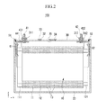
- FIG. 2 shows a cross-sectional view with respect to a II-II line in FIG. 1 .
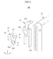
- FIG. 3 shows an exploded perspective view of a retainer, a lead tab, and an electrode assembly.
- FIG. 4 shows a cross-sectional view with respect to a IV-IV line in FIG. 3 .
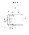
- FIG. 5 shows a cross-sectional view with respect to a V-V line in FIG. 3 .
- FIG. 6 shows an exploded perspective view of a retainer, a lead tab, and an electrode assembly in a rechargeable battery according to a second exemplary embodiment of the present invention.
- FIG. 7 shows a cross-sectional view with respect to a VII-VII line in FIG. 6 .
- FIG. 8 shows a cross-sectional view with respect to a VIII-VIII line in FIG. 6 .
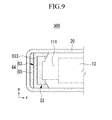
- FIG. 9 shows a cross-sectional view of a rechargeable battery according to a third exemplary embodiment of the present invention.
- Fig. 10 shows a schematic diagram of a vehicle including a rechargeable battery according to an embodiment of the present invention.
- FIG. 1 shows a perspective view of a rechargeable battery according to a first exemplary embodiment of the present invention
- FIG. 2 shows a cross-sectional view with respect to a II-II line in FIG. 1
- a rechargeable battery 100 includes a case 20 having an electrode assembly 10, a cap plate 30 closing and sealing an opening formed at one end of the case 20, electrode terminals 41 and 42 installed in terminal holes 311 and 312 of the cap plate 30, lead tabs 51 and 52 connecting the electrode terminals 41 and 42 to the electrode assembly 10, and retainers 61 and 62 interposed between the lead tabs 51 and 52 and an inner wall of the case 20.
- the lead tabs 51 and 52 are first welded to the respective uncoated regions 111 and 121 while the electrode assembly 10 is positioned outside the case, then the retainers 61, 62 are assembled to the respective lead tabs 51 and 52 and then this assembly is inserted into the case 20.
- the electrode assembly 10 includes a separator 13 that is an insulator, and an anode 11 and a cathode 12 disposed at both sides of the separator 13, and it is formed in the jelly roll form by winding the anode 11, the cathode 12, and the separator 13.
- the anode 11 and the cathode 12 include a current collecting part made of thin plate metal foil, and an active material being coated on a surface of the current collecting part. Also, the anode 11 and the cathode 12 can be divided into a coated region in which an active material is coated on the current collecting part, and uncoated regions 111 and 121 without an active material coated on the current collecting part.
- the coated region forms the major part of the anode 11 and the cathode 12 in the electrode assembly 10 (the major part preferably extends over more than 80%), and the uncoated regions 111 and 121 are disposed on both sides of the coated region in a jelly-roll state of the electrode assembly 10 where the anode 11, the cathode 12 and the separator 13 are formed in a jelly roll shape.
- the electrode assembly 10 in the jelly roll state forms an area with a wide front and rear, and the ends of the uncoated regions 111 and 121 form a narrow and long area (refer to FIG. 3 ), wherein the electrode assembly 10 is substantially a hexahedron.
- the case 20 forms the overall appearance of the rechargeable battery 100, and is formed of a conductive metal such as aluminum, an aluminum alloy, or nickel-plated steel.
- the conductive metal has an electrical conductivity (at 20°C) of more than 10 4 S/m, more preferably more than 10 5 S/m, more preferably more than 10 6 S/m, more preferably more than 10 7 S/m and still more preferably more than 3*10 7 S/m.
- the case 20 provides a space for housing the electrode assembly 10.
- the case 20 can be configured to be a hexahedron having an opening at one end so as to house the electrode assembly 10 that is hexahedral.
- the opening is oriented toward the top in the drawing.
- the case has planar side surfaces.
- the case has a cuboid shape.
- the cap plate 30 is made of a thin plate, and is combined with the opening of the case 20 to close and seal the opening.
- the cap plate 30 blocks the inside of the closed and sealed case 20 from the outside, and can also connect the inside and the outside if needed.
- the cap plate 30 includes an electrolyte injection hole 32 through which an electrolyte is injected inside the closed and sealed case 20.
- the electrolyte injection hole 32 is sealed by a sealing cap 33 after the electrolyte is injected.
- the cap plate 30 has a vent hole 35, and has a vent plate 34 that is thinner than the cap plate 30 and welded in the vent hole 35.
- the vent plate 34 is opened to discharge gas and prevent explosion of the rechargeable battery 100 when the internal pressure of the case 20 is increased to be greater than a predetermined value by gas that is generated by charging and discharging the electrode assembly 10.
- the electrode terminals 41 and 42 are installed in the terminal holes 311 and 312 formed in the cap plate 30, and draw out the anode 11 and the cathode 12 of the electrode assembly 10.
- the electrode terminals 41 and 42 are electrically insulated from the cap plate 30 since they are installed in the terminal holes 311 and 312 by providing external insulators 431 and 432 and internal insulators 441 and 442. Since the terminal holes 311 and 312, the internal insulators 441 and 442, and the external insulators 431 and 432 can be formed in a like configuration at the two electrode terminals 41 and 42, the end electrode terminal 41, the terminal hole 311, the internal insulator 441, and the external insulator 431 will be exemplarily described.
- the external insulator 431 is partially inserted into the terminal hole 311 from the external side of the cap plate 30 to electrically insulate the electrode terminal 41 and the cap plate 30. That is, the external insulator 431 insulates the external side of the electrode terminal 41 and the external side of the cap plate 30, and simultaneously insulates the external side of the electrode terminal 41 and the internal side of the terminal hole 311.
- the internal insulator 441 electrically insulates the cap plate 30 and the lead tab 51 corresponding to the terminal hole 311 inside the cap plate 30. That is, the internal insulator 441 insulates the top side of the lead tab 51 and the inside of the cap plate 30.
- FIG. 3 shows an exploded perspective view of a retainer 61, a lead tab 51, and an electrode assembly 10.
- the uncoated regions 111 and 121 and the retainers 61, 62 in the uncoated regions 111 and 121 are identically formed at the anode 11 and the cathode 12. Hence, only a part of the uncoated region 111 on the anode 11 is illustrated in Fig. 3 , and the uncoated region 111 on the anode 11 will be exemplified. Since the uncoated region 111 is continuously wound, the end of the uncoated region 111 forms lines that are gradually increased from the same center line.
- the lines at the end of the uncoated region 111 form a straight line unit that are formed as straight lines in the z-axis direction and are overlapped (or stacked) in the y-axis direction, and an arc portion is formed as a semicircle or as a semi-oval at both ends of the straight line unit in the z-axis direction and is overlapped in the z-axis direction.
- the lead tab 51 includes a connector 511 connected to the electrode terminal 41, a body 512 connected to the connector 511 and facing the end of the uncoated region 111 of the electrode assembly 10, and a current collector 513 connected to the body 512 and welded to both sides of the uncoated region 111.
- the connector 511 can be connected to the electrode terminal 41 by a caulking process which is inserting one end of the electrode terminal 41 into a hole of the connector 511 and transforming the end of the electrode terminal 41, and is provided between the cap plate 30 and the electrode assembly 10.
- the body 512 is connected to the connector 511 that is bent in the vertical direction from the horizontal direction to reach the end of the uncoated region 111, and is provided between the end of the uncoated region 111 and the case 20.
- the current collector 513 is formed to be on a plane corresponding to the front surface and the rear surface of the uncoated region 111 so as to be attached and welded to the surface of the uncoated region 111, and is provided between the front surface and the rear surface of the uncoated region 111 and the case 20.
- FIG. 4 shows a cross-sectional view with respect to a IV-IV line in FIG. 3
- FIG. 5 shows a cross-sectional view with respect to a V-V line in FIG. 3
- the retainer 61 is disposed at a gap G that is set between the lead tab 51 and the inner wall of the case 20 facing each other, and fixes the position of the electrode assembly 10 in the case 20. That is, the gap G between the lead tab 51 and the inner wall of the case 20 is filled with the retainer 61. Therefore, the retainer 61 prevents the electrode assembly 10 from moving along the x-axis direction in the case 20. As a result, durability to vibration of the electrode assembly 10 in the case 20 is improved, and the electric insulating property between the case 20 and the uncoated region 111 or between the case 20 and the lead tab 51 is improved.
- the retainer 61 is installed in the body 512 of the lead tab 51, and is provided between the body 512 and the case 20.
- the retainer 61 includes a buffer 613 attached to the body 512, a first hook 611 connected to the buffer 613 and hooked on the top of the body 512, and a second hook 612 connected to the buffer 613 and hooked on the bottom of the body 512.
- the first hook 611 is configured as a pair hooked on the top of the body 512 at both bottom sides of the connector 511. That is, the retainer 61 is stably installed at 3 points in the body 512 of the lead tab 51 by the first and second hooks 611 and 612.
- FIG. 6 shows an exploded perspective view of a retainer, a lead tab, and an electrode assembly in a rechargeable battery according to a second exemplary embodiment of the present invention
- FIG. 7 shows a cross-sectional view with respect to a VII-VII line in FIG. 6
- FIG. 8 shows a cross-sectional view with respect to a VIII-VIII line in FIG. 6 .
- a lead tab 53 in a rechargeable battery 200 according to the second exemplary embodiment, includes a connector 531 connected to the electrode terminal 41 and a current collector 532 connected to the connector 531 and welded at the end of the uncoated region 111 of the electrode assembly 10.
- the connector 531 can be connected to the electrode terminal 41 by a caulking process, and is provided between the cap plate 30 and the electrode assembly 10.
- the current collector 532 is connected to the connector 531 that is bent in the vertical direction from the horizontal direction to reach the end of the uncoated region 111, and is provided between the end of the uncoated region 111 and the case 20.
- a retainer 63 is disposed at the gap G1 that is set between the lead tab 53 and the inner wall of the case 20 facing each other, and fixes the position of the electrode assembly 10 in the case 20. That is, the gap G1 between the lead tab 53 and the inner wall of the case 20 is filled with the retainer 63. Therefore, the retainer 63 prevents the electrode assembly 10 from moving along the x-axis direction in the case 20. As a result, durability to vibration of the electrode assembly 10 in the case 20 is improved, and the electric insulating property between the case 20 and the uncoated region 111 or between the case 20 and the lead tab 53 is improved.
- the retainer 63 is installed in the current collector 532 of the lead tab 53, and is provided between of the current collector 532 and the case 20.
- the retainer 63 includes a buffer 633 attached to the current collector 532, a first hook 631 connected to the buffer 633 and hooked on the side of the current collector 532, and a second hook 632 connected to the buffer 633 and hooked in an installing hole 533 of the current collector 532.
- the first hook 631 is configured as a pair hooked on the current collector 532 at both sides of the current collector 532. That is, the retainer 63 is stably installed at 3 points in the current collector 532 of the lead tab 53 by the first and second hooks 631 and 632.
- the first hook 631 is provided between both sides of the current collector 532 and the case 20 (refer to FIG. 7 )
- the second hook 632 is provided between the current collector 532 and the case 20 (refer to FIG. 8 ).
- the retainer 63 according to the second exemplary embodiment is filled as the buffer 633 in the gap G1 that is set between the current collector 532 facing the end of the uncoated region 111 and the inner wall of the case 20, and is simultaneously filled as the first hook 631 in the gap G2 that is set between both ends of the current collector 532 facing the surface of the uncoated region 111 and the inner wall of the case 20 (front and rear side of the case) to thereby fix the position of the electrode assembly 10 in the case 20. That is, the retainer 63 prevents the electrode assembly 10 from moving in the x-axis and y-axis direction in the case 20. Hence, durability to vibration by the electrode assembly 10 in the case 20 is improved, and the electric insulating property between the case 20 and the uncoated region 111 or between the case 20 and the lead tab 53 is improved.
- FIG. 9 shows a cross-sectional view of a rechargeable battery according to a third exemplary embodiment of the present invention.
- a retainer 64 further includes a buffer member 65 between a buffer 633 of the retainer 63 according to the second exemplary embodiment and the inside of the case 20.
- the buffer member 65 can be formed with a foaming resin, a spring, or an elastic member.
- the rechargeable battery 300 discloses a configuration of the retainer 64 which is given by further adding the buffer member 65 to the retainer 63 compared to the second exemplary embodiment, and it is also possible to further apply a buffer member to the buffer 613 of the retainer 61 according to the first exemplary embodiment. Due to the elasticity of the buffer member 65, durability to vibration of the electrode assembly in the case is further improved, and also the electric insulating property between the case and the uncoated region or between the case and the lead tab is improved. Preferably, elasticity of the buffer is higher than the elasticity of the other components of the retainer.
- FIG. 10 shows a schematic diagram of a vehicle including a rechargeable battery according to an embodiment of the present invention.
- the vehicle may be, e.g., a hybrid electric vehicle, and all-electric vehicle, etc.
- the vehicle may include a power source that provides a motive power for the vehicle, as well as the rechargeable battery 300 described above.
- the rechargeable batteries 100 and 200 described above may be similarly used.
- a plurality of rechargeable batteries may be configured as a battery pack that provides electricity to and/or receives electricity from the power source.
- the rechargeable battery 300 may be housed in a housing 310, which may include a vent 320 to release gases, provide air flow to the rechargeable battery 300, etc.
Landscapes
- Chemical & Material Sciences (AREA)
- Chemical Kinetics & Catalysis (AREA)
- Electrochemistry (AREA)
- General Chemical & Material Sciences (AREA)
- Engineering & Computer Science (AREA)
- Manufacturing & Machinery (AREA)
- Connection Of Batteries Or Terminals (AREA)
- Secondary Cells (AREA)
- Cell Separators (AREA)
Applications Claiming Priority (2)
| Application Number | Priority Date | Filing Date | Title |
|---|---|---|---|
| US28285910P | 2010-04-12 | 2010-04-12 | |
| US12/801,967 US8628878B2 (en) | 2010-04-12 | 2010-07-06 | Hooked retainer for electrode body in rechargeable battery |
Publications (2)
| Publication Number | Publication Date |
|---|---|
| EP2375475A1 true EP2375475A1 (de) | 2011-10-12 |
| EP2375475B1 EP2375475B1 (de) | 2012-11-14 |
Family
ID=44146712
Family Applications (1)
| Application Number | Title | Priority Date | Filing Date |
|---|---|---|---|
| EP11152639A Active EP2375475B1 (de) | 2010-04-12 | 2011-01-31 | Wiederaufladbare Batterie |
Country Status (5)
| Country | Link |
|---|---|
| US (1) | US8628878B2 (de) |
| EP (1) | EP2375475B1 (de) |
| JP (1) | JP5204173B2 (de) |
| KR (1) | KR101223523B1 (de) |
| CN (1) | CN102214837B (de) |
Cited By (5)
| Publication number | Priority date | Publication date | Assignee | Title |
|---|---|---|---|---|
| EP2458659A1 (de) * | 2010-11-25 | 2012-05-30 | SB LiMotive Co., Ltd. | Wiederaufladbare Batterie |
| EP2581965A1 (de) * | 2011-10-13 | 2013-04-17 | Samsung SDI Co., Ltd. | Wiederaufladbare Batterie |
| EP2602841A1 (de) * | 2011-12-09 | 2013-06-12 | Samsung SDI Co., Ltd. | Batterie |
| EP3024064A1 (de) * | 2014-11-19 | 2016-05-25 | Samsung SDI Co., Ltd. | Sekundärbatterie |
| EP4560794A1 (de) * | 2023-11-23 | 2025-05-28 | Samsung Sdi Co., Ltd. | Sekundärbatterie mit haltern |
Families Citing this family (26)
| Publication number | Priority date | Publication date | Assignee | Title |
|---|---|---|---|---|
| JP5852926B2 (ja) * | 2011-07-01 | 2016-02-03 | 株式会社Gsユアサ | 蓄電素子及びスペーサ |
| KR20140010633A (ko) * | 2012-07-16 | 2014-01-27 | 삼성에스디아이 주식회사 | 배터리 팩 |
| KR20140096815A (ko) * | 2013-01-29 | 2014-08-06 | 삼성에스디아이 주식회사 | 이차 전지 |
| US20140272490A1 (en) * | 2013-03-12 | 2014-09-18 | Samsung Sdi Co., Ltd. | Rechargeable battery |
| KR101741028B1 (ko) * | 2013-04-08 | 2017-05-29 | 삼성에스디아이 주식회사 | 전지 유니트 및 이를 채용한 전지 모듈 |
| US10333113B2 (en) | 2013-06-19 | 2019-06-25 | Samsung Sdi Co., Ltd. | Rechargeable battery having retainer |
| KR101744087B1 (ko) * | 2013-06-25 | 2017-06-07 | 삼성에스디아이 주식회사 | 이차 전지 |
| KR101718060B1 (ko) * | 2013-11-22 | 2017-03-20 | 삼성에스디아이 주식회사 | 전극 집전체의 굽힘 강도를 강화한 이차 전지 |
| KR101749507B1 (ko) * | 2013-12-18 | 2017-07-03 | 삼성에스디아이 주식회사 | 전극 조립체의 절연을 강화한 이차 전지 |
| KR20150089311A (ko) | 2014-01-27 | 2015-08-05 | 삼성에스디아이 주식회사 | 이차 전지 |
| DE102014108803A1 (de) * | 2014-06-24 | 2015-12-24 | Dr. Ing. H.C. F. Porsche Aktiengesellschaft | Energiespeicher für ein Fahrzeug und Verfahren zum Bereitstellen eines Energiespeichers für ein Fahrzeug |
| KR101586949B1 (ko) | 2014-09-01 | 2016-01-20 | 주식회사다스 | 시트백 래치 |
| KR102371196B1 (ko) * | 2017-08-31 | 2022-03-07 | 삼성에스디아이 주식회사 | 이차 전지 |
| KR102450146B1 (ko) * | 2017-08-31 | 2022-10-04 | 삼성에스디아이 주식회사 | 이차 전지 |
| KR102571487B1 (ko) * | 2017-08-31 | 2023-08-28 | 삼성에스디아이 주식회사 | 이차 전지 및 그 조립 방법 |
| JP7059548B2 (ja) * | 2017-09-27 | 2022-04-26 | 株式会社Gsユアサ | 蓄電素子 |
| JP6479924B1 (ja) * | 2017-10-03 | 2019-03-06 | カルソニックカンセイ株式会社 | 組電池の製造方法及び組電池 |
| JP6962167B2 (ja) * | 2017-12-12 | 2021-11-05 | 三洋電機株式会社 | 二次電池 |
| CN108198989B (zh) * | 2018-01-16 | 2021-01-12 | 宁德时代新能源科技股份有限公司 | 连接构件和充电电池 |
| CN111969166B (zh) * | 2018-01-16 | 2022-11-29 | 宁德时代新能源科技股份有限公司 | 集流构件和电池 |
| CN111384350B (zh) * | 2018-12-29 | 2024-10-15 | 宁德时代新能源科技股份有限公司 | 二次电池以及电池模组 |
| KR102777223B1 (ko) * | 2019-03-11 | 2025-03-07 | 삼성에스디아이 주식회사 | 이차 전지 |
| KR102890541B1 (ko) * | 2019-05-14 | 2025-11-26 | 삼성에스디아이 주식회사 | 이차 전지 |
| CN112397817B (zh) * | 2019-07-30 | 2022-03-18 | 比亚迪股份有限公司 | 固态锂电池及其制备方法 |
| JP7529619B2 (ja) * | 2021-06-09 | 2024-08-06 | プライムプラネットエナジー&ソリューションズ株式会社 | 固定部材を備えた電池 |
| WO2025218258A1 (zh) * | 2024-04-15 | 2025-10-23 | 惠州亿纬动力电池有限公司 | 集流件、顶盖组件、电池和用电设备 |
Citations (3)
| Publication number | Priority date | Publication date | Assignee | Title |
|---|---|---|---|---|
| US20060024578A1 (en) * | 2004-07-28 | 2006-02-02 | Lee Sang-Won | Secondary battery |
| US20070196729A1 (en) * | 2006-02-21 | 2007-08-23 | Sanyo Electric Co., Ltd. | Prismatic battery |
| US20080038627A1 (en) * | 2006-08-11 | 2008-02-14 | Sanyo Electric Co., Ltd. | Non-aqueous electrolyte secondary cell |
Family Cites Families (4)
| Publication number | Priority date | Publication date | Assignee | Title |
|---|---|---|---|---|
| JP3536391B2 (ja) * | 1994-12-19 | 2004-06-07 | ソニー株式会社 | 巻回電極素子体及びその製造方法並びに巻回電極素子体を用いた電池の製造方法 |
| KR100551050B1 (ko) * | 2003-11-24 | 2006-02-09 | 삼성에스디아이 주식회사 | 형상기억합금에 의한 이차 전지의 캡 조립체 |
| KR100591425B1 (ko) * | 2004-09-09 | 2006-06-21 | 삼성에스디아이 주식회사 | 캔형 이차전지 |
| KR100637445B1 (ko) | 2005-07-07 | 2006-10-20 | 삼성에스디아이 주식회사 | 이차 전지 |
-
2010
- 2010-07-06 US US12/801,967 patent/US8628878B2/en active Active
- 2010-08-16 KR KR1020100078849A patent/KR101223523B1/ko active Active
- 2010-08-30 CN CN201010269387.2A patent/CN102214837B/zh active Active
- 2010-08-30 JP JP2010192487A patent/JP5204173B2/ja active Active
-
2011
- 2011-01-31 EP EP11152639A patent/EP2375475B1/de active Active
Patent Citations (3)
| Publication number | Priority date | Publication date | Assignee | Title |
|---|---|---|---|---|
| US20060024578A1 (en) * | 2004-07-28 | 2006-02-02 | Lee Sang-Won | Secondary battery |
| US20070196729A1 (en) * | 2006-02-21 | 2007-08-23 | Sanyo Electric Co., Ltd. | Prismatic battery |
| US20080038627A1 (en) * | 2006-08-11 | 2008-02-14 | Sanyo Electric Co., Ltd. | Non-aqueous electrolyte secondary cell |
Cited By (13)
| Publication number | Priority date | Publication date | Assignee | Title |
|---|---|---|---|---|
| US8734974B2 (en) | 2010-11-25 | 2014-05-27 | Samsung Sdi Co., Ltd. | Rechargeable battery |
| EP2458659A1 (de) * | 2010-11-25 | 2012-05-30 | SB LiMotive Co., Ltd. | Wiederaufladbare Batterie |
| CN103050656B (zh) * | 2011-10-13 | 2016-08-31 | 三星Sdi株式会社 | 可再充电电池 |
| CN103050656A (zh) * | 2011-10-13 | 2013-04-17 | 三星Sdi株式会社 | 可再充电电池 |
| US8889292B2 (en) | 2011-10-13 | 2014-11-18 | Samsung Sdi Co., Ltd. | Rechargeable battery |
| EP2581965A1 (de) * | 2011-10-13 | 2013-04-17 | Samsung SDI Co., Ltd. | Wiederaufladbare Batterie |
| EP2602841A1 (de) * | 2011-12-09 | 2013-06-12 | Samsung SDI Co., Ltd. | Batterie |
| CN103165857A (zh) * | 2011-12-09 | 2013-06-19 | 三星Sdi株式会社 | 二次电池 |
| US8962177B2 (en) | 2011-12-09 | 2015-02-24 | Samsung Sdi Co., Ltd. | Secondary battery |
| CN103165857B (zh) * | 2011-12-09 | 2017-07-07 | 三星Sdi株式会社 | 二次电池 |
| EP3024064A1 (de) * | 2014-11-19 | 2016-05-25 | Samsung SDI Co., Ltd. | Sekundärbatterie |
| US10396336B2 (en) | 2014-11-19 | 2019-08-27 | Samsung Sdi Co., Ltd. | Secondary battery |
| EP4560794A1 (de) * | 2023-11-23 | 2025-05-28 | Samsung Sdi Co., Ltd. | Sekundärbatterie mit haltern |
Also Published As
| Publication number | Publication date |
|---|---|
| US8628878B2 (en) | 2014-01-14 |
| EP2375475B1 (de) | 2012-11-14 |
| CN102214837A (zh) | 2011-10-12 |
| CN102214837B (zh) | 2014-06-04 |
| US20110250491A1 (en) | 2011-10-13 |
| KR20110114411A (ko) | 2011-10-19 |
| KR101223523B1 (ko) | 2013-01-17 |
| JP2011222474A (ja) | 2011-11-04 |
| JP5204173B2 (ja) | 2013-06-05 |
Similar Documents
| Publication | Publication Date | Title |
|---|---|---|
| EP2375475B1 (de) | Wiederaufladbare Batterie | |
| US12218302B2 (en) | Rechargeable battery and pack of the same | |
| EP2287942B1 (de) | Wiederaufladbare Batterie | |
| CN102035017B (zh) | 可再充电电池 | |
| CN113966562B (zh) | 可再充电电池 | |
| US10673055B2 (en) | Secondary battery | |
| EP2736097B1 (de) | Wiederaufladbare Batterie und Modul daraus | |
| EP3007246B1 (de) | Wiederaufladbare batterie | |
| US8501346B2 (en) | Rechargeable battery | |
| CN105789493B (zh) | 可再充电电池和可再充电电池组 | |
| EP2362461A1 (de) | Wiederaufladbare Batterie | |
| US20110300419A1 (en) | Secondary battery | |
| US10033026B2 (en) | Rechargeable battery having an external terminal and module thereof | |
| KR20130116087A (ko) | 이차 전지 및 그 모듈 | |
| CN104241560A (zh) | 可再充电电池 | |
| EP2849263A1 (de) | Wiederaufladbare Batterie | |
| US11075434B2 (en) | Rechargeable battery | |
| CN104282851A (zh) | 可再充电电池 | |
| CN106450407A (zh) | 二次电池 | |
| US8142921B2 (en) | Rechargeable battery and battery module | |
| CN106058134A (zh) | 可再充电电池 | |
| KR20170009132A (ko) | 이차 전지 및 이를 이용한 전지 모듈 | |
| US20150214536A1 (en) | Secondary battery | |
| KR20180047810A (ko) | 이차 전지 | |
| KR20180054278A (ko) | 이차 전지 |
Legal Events
| Date | Code | Title | Description |
|---|---|---|---|
| PUAI | Public reference made under article 153(3) epc to a published international application that has entered the european phase |
Free format text: ORIGINAL CODE: 0009012 |
|
| AK | Designated contracting states |
Kind code of ref document: A1 Designated state(s): AL AT BE BG CH CY CZ DE DK EE ES FI FR GB GR HR HU IE IS IT LI LT LU LV MC MK MT NL NO PL PT RO RS SE SI SK SM TR |
|
| AX | Request for extension of the european patent |
Extension state: BA ME |
|
| 17P | Request for examination filed |
Effective date: 20120326 |
|
| REG | Reference to a national code |
Ref country code: DE Ref legal event code: R079 Ref document number: 602011000426 Country of ref document: DE Free format text: PREVIOUS MAIN CLASS: H01M0002260000 Ipc: H01M0010052000 |
|
| GRAP | Despatch of communication of intention to grant a patent |
Free format text: ORIGINAL CODE: EPIDOSNIGR1 |
|
| RIC1 | Information provided on ipc code assigned before grant |
Ipc: H01M 10/0587 20100101ALI20120619BHEP Ipc: H01M 2/26 20060101AFI20120619BHEP Ipc: H01M 2/18 20060101ALI20120619BHEP Ipc: H01M 2/02 20060101ALI20120619BHEP Ipc: H01M 2/34 20060101ALI20120619BHEP |
|
| RIC1 | Information provided on ipc code assigned before grant |
Ipc: H01M 10/0587 20100101ALI20120629BHEP Ipc: H01M 2/26 20060101ALI20120629BHEP Ipc: H01M 10/052 20100101AFI20120629BHEP Ipc: H01M 2/02 20060101ALI20120629BHEP Ipc: H01M 2/34 20060101ALI20120629BHEP Ipc: H01M 2/18 20060101ALI20120629BHEP |
|
| RIN1 | Information on inventor provided before grant (corrected) |
Inventor name: BYUN, SANG-WON Inventor name: KIM, SUNG-BAE Inventor name: KIM, YONG-SAM |
|
| GRAS | Grant fee paid |
Free format text: ORIGINAL CODE: EPIDOSNIGR3 |
|
| GRAA | (expected) grant |
Free format text: ORIGINAL CODE: 0009210 |
|
| AK | Designated contracting states |
Kind code of ref document: B1 Designated state(s): AL AT BE BG CH CY CZ DE DK EE ES FI FR GB GR HR HU IE IS IT LI LT LU LV MC MK MT NL NO PL PT RO RS SE SI SK SM TR |
|
| REG | Reference to a national code |
Ref country code: GB Ref legal event code: FG4D |
|
| REG | Reference to a national code |
Ref country code: CH Ref legal event code: EP Ref country code: AT Ref legal event code: REF Ref document number: 584391 Country of ref document: AT Kind code of ref document: T Effective date: 20121115 |
|
| REG | Reference to a national code |
Ref country code: IE Ref legal event code: FG4D |
|
| REG | Reference to a national code |
Ref country code: DE Ref legal event code: R096 Ref document number: 602011000426 Country of ref document: DE Effective date: 20130110 |
|
| REG | Reference to a national code |
Ref country code: FR Ref legal event code: TQ Owner name: SAMSUNG SDI CO., LTD., KR Effective date: 20130218 Ref country code: FR Ref legal event code: TQ Owner name: ROBERT BOSCH GMBH, DE Effective date: 20130218 |
|
| REG | Reference to a national code |
Ref country code: NL Ref legal event code: VDEP Effective date: 20121114 |
|
| REG | Reference to a national code |
Ref country code: AT Ref legal event code: MK05 Ref document number: 584391 Country of ref document: AT Kind code of ref document: T Effective date: 20121114 |
|
| REG | Reference to a national code |
Ref country code: LT Ref legal event code: MG4D |
|
| PG25 | Lapsed in a contracting state [announced via postgrant information from national office to epo] |
Ref country code: LT Free format text: LAPSE BECAUSE OF FAILURE TO SUBMIT A TRANSLATION OF THE DESCRIPTION OR TO PAY THE FEE WITHIN THE PRESCRIBED TIME-LIMIT Effective date: 20121114 Ref country code: SE Free format text: LAPSE BECAUSE OF FAILURE TO SUBMIT A TRANSLATION OF THE DESCRIPTION OR TO PAY THE FEE WITHIN THE PRESCRIBED TIME-LIMIT Effective date: 20121114 Ref country code: NO Free format text: LAPSE BECAUSE OF FAILURE TO SUBMIT A TRANSLATION OF THE DESCRIPTION OR TO PAY THE FEE WITHIN THE PRESCRIBED TIME-LIMIT Effective date: 20130214 Ref country code: HR Free format text: LAPSE BECAUSE OF FAILURE TO SUBMIT A TRANSLATION OF THE DESCRIPTION OR TO PAY THE FEE WITHIN THE PRESCRIBED TIME-LIMIT Effective date: 20121114 Ref country code: ES Free format text: LAPSE BECAUSE OF FAILURE TO SUBMIT A TRANSLATION OF THE DESCRIPTION OR TO PAY THE FEE WITHIN THE PRESCRIBED TIME-LIMIT Effective date: 20130225 Ref country code: FI Free format text: LAPSE BECAUSE OF FAILURE TO SUBMIT A TRANSLATION OF THE DESCRIPTION OR TO PAY THE FEE WITHIN THE PRESCRIBED TIME-LIMIT Effective date: 20121114 |
|
| REG | Reference to a national code |
Ref country code: GB Ref legal event code: 732E Free format text: REGISTERED BETWEEN 20130425 AND 20130501 |
|
| REG | Reference to a national code |
Ref country code: DE Ref legal event code: R081 Ref document number: 602011000426 Country of ref document: DE Owner name: ROBERT BOSCH GMBH, DE Free format text: FORMER OWNER: SB LIMOTIVE CO., LTD., YONGIN-SI, GYEONGGI-DO, KR Effective date: 20130410 Ref country code: DE Ref legal event code: R081 Ref document number: 602011000426 Country of ref document: DE Owner name: SAMSUNG SDI CO., LTD., YONGIN-SI, KR Free format text: FORMER OWNER: SB LIMOTIVE CO., LTD., YONGIN-SI, GYEONGGI-DO, KR Effective date: 20130410 Ref country code: DE Ref legal event code: R081 Ref document number: 602011000426 Country of ref document: DE Owner name: SAMSUNG SDI CO., LTD., KR Free format text: FORMER OWNER: SB LIMOTIVE CO., LTD., YONGIN-SI, KR Effective date: 20130410 Ref country code: DE Ref legal event code: R081 Ref document number: 602011000426 Country of ref document: DE Owner name: ROBERT BOSCH GMBH, DE Free format text: FORMER OWNER: SB LIMOTIVE CO., LTD., YONGIN-SI, KR Effective date: 20130410 |
|
| PG25 | Lapsed in a contracting state [announced via postgrant information from national office to epo] |
Ref country code: GR Free format text: LAPSE BECAUSE OF FAILURE TO SUBMIT A TRANSLATION OF THE DESCRIPTION OR TO PAY THE FEE WITHIN THE PRESCRIBED TIME-LIMIT Effective date: 20130215 Ref country code: PL Free format text: LAPSE BECAUSE OF FAILURE TO SUBMIT A TRANSLATION OF THE DESCRIPTION OR TO PAY THE FEE WITHIN THE PRESCRIBED TIME-LIMIT Effective date: 20121114 Ref country code: PT Free format text: LAPSE BECAUSE OF FAILURE TO SUBMIT A TRANSLATION OF THE DESCRIPTION OR TO PAY THE FEE WITHIN THE PRESCRIBED TIME-LIMIT Effective date: 20130314 Ref country code: SI Free format text: LAPSE BECAUSE OF FAILURE TO SUBMIT A TRANSLATION OF THE DESCRIPTION OR TO PAY THE FEE WITHIN THE PRESCRIBED TIME-LIMIT Effective date: 20121114 Ref country code: BE Free format text: LAPSE BECAUSE OF FAILURE TO SUBMIT A TRANSLATION OF THE DESCRIPTION OR TO PAY THE FEE WITHIN THE PRESCRIBED TIME-LIMIT Effective date: 20121114 Ref country code: LV Free format text: LAPSE BECAUSE OF FAILURE TO SUBMIT A TRANSLATION OF THE DESCRIPTION OR TO PAY THE FEE WITHIN THE PRESCRIBED TIME-LIMIT Effective date: 20121114 |
|
| PG25 | Lapsed in a contracting state [announced via postgrant information from national office to epo] |
Ref country code: AT Free format text: LAPSE BECAUSE OF FAILURE TO SUBMIT A TRANSLATION OF THE DESCRIPTION OR TO PAY THE FEE WITHIN THE PRESCRIBED TIME-LIMIT Effective date: 20121114 |
|
| PG25 | Lapsed in a contracting state [announced via postgrant information from national office to epo] |
Ref country code: DK Free format text: LAPSE BECAUSE OF FAILURE TO SUBMIT A TRANSLATION OF THE DESCRIPTION OR TO PAY THE FEE WITHIN THE PRESCRIBED TIME-LIMIT Effective date: 20121114 Ref country code: RS Free format text: LAPSE BECAUSE OF FAILURE TO SUBMIT A TRANSLATION OF THE DESCRIPTION OR TO PAY THE FEE WITHIN THE PRESCRIBED TIME-LIMIT Effective date: 20121114 Ref country code: EE Free format text: LAPSE BECAUSE OF FAILURE TO SUBMIT A TRANSLATION OF THE DESCRIPTION OR TO PAY THE FEE WITHIN THE PRESCRIBED TIME-LIMIT Effective date: 20121114 Ref country code: CZ Free format text: LAPSE BECAUSE OF FAILURE TO SUBMIT A TRANSLATION OF THE DESCRIPTION OR TO PAY THE FEE WITHIN THE PRESCRIBED TIME-LIMIT Effective date: 20121114 Ref country code: SK Free format text: LAPSE BECAUSE OF FAILURE TO SUBMIT A TRANSLATION OF THE DESCRIPTION OR TO PAY THE FEE WITHIN THE PRESCRIBED TIME-LIMIT Effective date: 20121114 Ref country code: BG Free format text: LAPSE BECAUSE OF FAILURE TO SUBMIT A TRANSLATION OF THE DESCRIPTION OR TO PAY THE FEE WITHIN THE PRESCRIBED TIME-LIMIT Effective date: 20130214 |
|
| PG25 | Lapsed in a contracting state [announced via postgrant information from national office to epo] |
Ref country code: RO Free format text: LAPSE BECAUSE OF FAILURE TO SUBMIT A TRANSLATION OF THE DESCRIPTION OR TO PAY THE FEE WITHIN THE PRESCRIBED TIME-LIMIT Effective date: 20121114 Ref country code: MC Free format text: LAPSE BECAUSE OF NON-PAYMENT OF DUE FEES Effective date: 20130131 Ref country code: IT Free format text: LAPSE BECAUSE OF FAILURE TO SUBMIT A TRANSLATION OF THE DESCRIPTION OR TO PAY THE FEE WITHIN THE PRESCRIBED TIME-LIMIT Effective date: 20121114 Ref country code: NL Free format text: LAPSE BECAUSE OF FAILURE TO SUBMIT A TRANSLATION OF THE DESCRIPTION OR TO PAY THE FEE WITHIN THE PRESCRIBED TIME-LIMIT Effective date: 20121114 |
|
| PLBE | No opposition filed within time limit |
Free format text: ORIGINAL CODE: 0009261 |
|
| STAA | Information on the status of an ep patent application or granted ep patent |
Free format text: STATUS: NO OPPOSITION FILED WITHIN TIME LIMIT |
|
| 26N | No opposition filed |
Effective date: 20130815 |
|
| REG | Reference to a national code |
Ref country code: IE Ref legal event code: MM4A |
|
| PG25 | Lapsed in a contracting state [announced via postgrant information from national office to epo] |
Ref country code: CY Free format text: LAPSE BECAUSE OF FAILURE TO SUBMIT A TRANSLATION OF THE DESCRIPTION OR TO PAY THE FEE WITHIN THE PRESCRIBED TIME-LIMIT Effective date: 20121114 |
|
| REG | Reference to a national code |
Ref country code: DE Ref legal event code: R097 Ref document number: 602011000426 Country of ref document: DE Effective date: 20130815 |
|
| PG25 | Lapsed in a contracting state [announced via postgrant information from national office to epo] |
Ref country code: AL Free format text: LAPSE BECAUSE OF FAILURE TO SUBMIT A TRANSLATION OF THE DESCRIPTION OR TO PAY THE FEE WITHIN THE PRESCRIBED TIME-LIMIT Effective date: 20121114 Ref country code: IE Free format text: LAPSE BECAUSE OF NON-PAYMENT OF DUE FEES Effective date: 20130131 |
|
| PG25 | Lapsed in a contracting state [announced via postgrant information from national office to epo] |
Ref country code: MT Free format text: LAPSE BECAUSE OF FAILURE TO SUBMIT A TRANSLATION OF THE DESCRIPTION OR TO PAY THE FEE WITHIN THE PRESCRIBED TIME-LIMIT Effective date: 20121114 |
|
| REG | Reference to a national code |
Ref country code: CH Ref legal event code: PL |
|
| PG25 | Lapsed in a contracting state [announced via postgrant information from national office to epo] |
Ref country code: LI Free format text: LAPSE BECAUSE OF NON-PAYMENT OF DUE FEES Effective date: 20140131 Ref country code: CH Free format text: LAPSE BECAUSE OF NON-PAYMENT OF DUE FEES Effective date: 20140131 |
|
| PG25 | Lapsed in a contracting state [announced via postgrant information from national office to epo] |
Ref country code: SM Free format text: LAPSE BECAUSE OF FAILURE TO SUBMIT A TRANSLATION OF THE DESCRIPTION OR TO PAY THE FEE WITHIN THE PRESCRIBED TIME-LIMIT Effective date: 20121114 |
|
| PG25 | Lapsed in a contracting state [announced via postgrant information from national office to epo] |
Ref country code: TR Free format text: LAPSE BECAUSE OF FAILURE TO SUBMIT A TRANSLATION OF THE DESCRIPTION OR TO PAY THE FEE WITHIN THE PRESCRIBED TIME-LIMIT Effective date: 20121114 |
|
| PG25 | Lapsed in a contracting state [announced via postgrant information from national office to epo] |
Ref country code: MK Free format text: LAPSE BECAUSE OF FAILURE TO SUBMIT A TRANSLATION OF THE DESCRIPTION OR TO PAY THE FEE WITHIN THE PRESCRIBED TIME-LIMIT Effective date: 20121114 Ref country code: HU Free format text: LAPSE BECAUSE OF FAILURE TO SUBMIT A TRANSLATION OF THE DESCRIPTION OR TO PAY THE FEE WITHIN THE PRESCRIBED TIME-LIMIT; INVALID AB INITIO Effective date: 20110131 Ref country code: LU Free format text: LAPSE BECAUSE OF NON-PAYMENT OF DUE FEES Effective date: 20130131 |
|
| REG | Reference to a national code |
Ref country code: FR Ref legal event code: PLFP Year of fee payment: 6 |
|
| PG25 | Lapsed in a contracting state [announced via postgrant information from national office to epo] |
Ref country code: IS Free format text: LAPSE BECAUSE OF FAILURE TO SUBMIT A TRANSLATION OF THE DESCRIPTION OR TO PAY THE FEE WITHIN THE PRESCRIBED TIME-LIMIT Effective date: 20121114 |
|
| REG | Reference to a national code |
Ref country code: FR Ref legal event code: PLFP Year of fee payment: 7 |
|
| REG | Reference to a national code |
Ref country code: FR Ref legal event code: PLFP Year of fee payment: 8 |
|
| P01 | Opt-out of the competence of the unified patent court (upc) registered |
Effective date: 20230528 |
|
| PGFP | Annual fee paid to national office [announced via postgrant information from national office to epo] |
Ref country code: DE Payment date: 20241231 Year of fee payment: 15 |
|
| PGFP | Annual fee paid to national office [announced via postgrant information from national office to epo] |
Ref country code: GB Payment date: 20250102 Year of fee payment: 15 |
|
| PGFP | Annual fee paid to national office [announced via postgrant information from national office to epo] |
Ref country code: FR Payment date: 20251231 Year of fee payment: 16 |