EP2375249B1 - Vorrichtungen und Verfahren zum Trennen von Plasma aus einer Blutprobe - Google Patents
Vorrichtungen und Verfahren zum Trennen von Plasma aus einer Blutprobe Download PDFInfo
- Publication number
- EP2375249B1 EP2375249B1 EP11160450.0A EP11160450A EP2375249B1 EP 2375249 B1 EP2375249 B1 EP 2375249B1 EP 11160450 A EP11160450 A EP 11160450A EP 2375249 B1 EP2375249 B1 EP 2375249B1
- Authority
- EP
- European Patent Office
- Prior art keywords
- absorptive
- layer
- plasma
- backing
- separating
- Prior art date
- Legal status (The legal status is an assumption and is not a legal conclusion. Google has not performed a legal analysis and makes no representation as to the accuracy of the status listed.)
- Active
Links
- 210000004369 blood Anatomy 0.000 title claims description 57
- 239000008280 blood Substances 0.000 title claims description 57
- 238000000034 method Methods 0.000 title claims description 12
- 230000008569 process Effects 0.000 title claims description 9
- 239000010410 layer Substances 0.000 claims description 212
- 239000000853 adhesive Substances 0.000 claims description 71
- 230000001070 adhesive effect Effects 0.000 claims description 71
- 239000000463 material Substances 0.000 claims description 23
- 239000012790 adhesive layer Substances 0.000 claims description 16
- 230000001413 cellular effect Effects 0.000 claims description 11
- 210000000601 blood cell Anatomy 0.000 claims description 7
- 238000010828 elution Methods 0.000 claims description 6
- 210000002381 plasma Anatomy 0.000 description 91
- 238000000926 separation method Methods 0.000 description 23
- 238000011118 depth filtration Methods 0.000 description 21
- 238000004458 analytical method Methods 0.000 description 20
- 239000012528 membrane Substances 0.000 description 20
- 238000000576 coating method Methods 0.000 description 14
- 239000011248 coating agent Substances 0.000 description 12
- 238000004891 communication Methods 0.000 description 10
- 239000012530 fluid Substances 0.000 description 10
- 238000012360 testing method Methods 0.000 description 10
- 239000000306 component Substances 0.000 description 8
- 241000725303 Human immunodeficiency virus Species 0.000 description 5
- 238000009792 diffusion process Methods 0.000 description 5
- 229920006395 saturated elastomer Polymers 0.000 description 5
- 210000002966 serum Anatomy 0.000 description 5
- 238000005452 bending Methods 0.000 description 4
- 239000012503 blood component Substances 0.000 description 4
- 239000003292 glue Substances 0.000 description 4
- 230000003993 interaction Effects 0.000 description 4
- 239000002245 particle Substances 0.000 description 4
- 238000006243 chemical reaction Methods 0.000 description 3
- 238000001035 drying Methods 0.000 description 3
- 230000000694 effects Effects 0.000 description 3
- 238000005516 engineering process Methods 0.000 description 3
- 230000003287 optical effect Effects 0.000 description 3
- 239000000123 paper Substances 0.000 description 3
- 206010053567 Coagulopathies Diseases 0.000 description 2
- 241000700605 Viruses Species 0.000 description 2
- 238000010521 absorption reaction Methods 0.000 description 2
- 210000001772 blood platelet Anatomy 0.000 description 2
- 230000035602 clotting Effects 0.000 description 2
- 239000000470 constituent Substances 0.000 description 2
- 238000011109 contamination Methods 0.000 description 2
- 238000005520 cutting process Methods 0.000 description 2
- 230000001419 dependent effect Effects 0.000 description 2
- 238000001514 detection method Methods 0.000 description 2
- 210000003743 erythrocyte Anatomy 0.000 description 2
- 238000005534 hematocrit Methods 0.000 description 2
- 208000015181 infectious disease Diseases 0.000 description 2
- 239000002346 layers by function Substances 0.000 description 2
- 210000000265 leukocyte Anatomy 0.000 description 2
- 239000007788 liquid Substances 0.000 description 2
- 150000007523 nucleic acids Chemical class 0.000 description 2
- 102000039446 nucleic acids Human genes 0.000 description 2
- 108020004707 nucleic acids Proteins 0.000 description 2
- 230000037361 pathway Effects 0.000 description 2
- 239000004033 plastic Substances 0.000 description 2
- 238000003752 polymerase chain reaction Methods 0.000 description 2
- 238000003825 pressing Methods 0.000 description 2
- 230000004044 response Effects 0.000 description 2
- 239000007787 solid Substances 0.000 description 2
- 239000000126 substance Substances 0.000 description 2
- 238000012546 transfer Methods 0.000 description 2
- 206010018910 Haemolysis Diseases 0.000 description 1
- 239000004640 Melamine resin Substances 0.000 description 1
- 229920000877 Melamine resin Polymers 0.000 description 1
- 239000002313 adhesive film Substances 0.000 description 1
- 230000000274 adsorptive effect Effects 0.000 description 1
- 230000003321 amplification Effects 0.000 description 1
- 239000012491 analyte Substances 0.000 description 1
- 238000003556 assay Methods 0.000 description 1
- 238000004159 blood analysis Methods 0.000 description 1
- 210000004027 cell Anatomy 0.000 description 1
- 239000011093 chipboard Substances 0.000 description 1
- 230000006835 compression Effects 0.000 description 1
- 238000007906 compression Methods 0.000 description 1
- 238000001816 cooling Methods 0.000 description 1
- 230000006378 damage Effects 0.000 description 1
- 238000000354 decomposition reaction Methods 0.000 description 1
- 230000006837 decompression Effects 0.000 description 1
- 239000002274 desiccant Substances 0.000 description 1
- 238000010586 diagram Methods 0.000 description 1
- 210000000624 ear auricle Anatomy 0.000 description 1
- 230000002349 favourable effect Effects 0.000 description 1
- 239000003365 glass fiber Substances 0.000 description 1
- 230000002489 hematologic effect Effects 0.000 description 1
- 230000008588 hemolysis Effects 0.000 description 1
- 230000000984 immunochemical effect Effects 0.000 description 1
- 238000003475 lamination Methods 0.000 description 1
- 229920002521 macromolecule Polymers 0.000 description 1
- 230000014759 maintenance of location Effects 0.000 description 1
- 238000012986 modification Methods 0.000 description 1
- 230000004048 modification Effects 0.000 description 1
- 238000003199 nucleic acid amplification method Methods 0.000 description 1
- 239000011148 porous material Substances 0.000 description 1
- 238000004080 punching Methods 0.000 description 1
- 210000003462 vein Anatomy 0.000 description 1
Images
Classifications
-
- G—PHYSICS
- G01—MEASURING; TESTING
- G01N—INVESTIGATING OR ANALYSING MATERIALS BY DETERMINING THEIR CHEMICAL OR PHYSICAL PROPERTIES
- G01N33/00—Investigating or analysing materials by specific methods not covered by groups G01N1/00 - G01N31/00
- G01N33/48—Biological material, e.g. blood, urine; Haemocytometers
- G01N33/483—Physical analysis of biological material
- G01N33/487—Physical analysis of biological material of liquid biological material
- G01N33/49—Blood
- G01N33/491—Blood by separating the blood components
-
- B—PERFORMING OPERATIONS; TRANSPORTING
- B01—PHYSICAL OR CHEMICAL PROCESSES OR APPARATUS IN GENERAL
- B01L—CHEMICAL OR PHYSICAL LABORATORY APPARATUS FOR GENERAL USE
- B01L3/00—Containers or dishes for laboratory use, e.g. laboratory glassware; Droppers
- B01L3/50—Containers for the purpose of retaining a material to be analysed, e.g. test tubes
- B01L3/502—Containers for the purpose of retaining a material to be analysed, e.g. test tubes with fluid transport, e.g. in multi-compartment structures
- B01L3/5023—Containers for the purpose of retaining a material to be analysed, e.g. test tubes with fluid transport, e.g. in multi-compartment structures with a sample being transported to, and subsequently stored in an absorbent for analysis
-
- B—PERFORMING OPERATIONS; TRANSPORTING
- B01—PHYSICAL OR CHEMICAL PROCESSES OR APPARATUS IN GENERAL
- B01L—CHEMICAL OR PHYSICAL LABORATORY APPARATUS FOR GENERAL USE
- B01L2200/00—Solutions for specific problems relating to chemical or physical laboratory apparatus
- B01L2200/02—Adapting objects or devices to another
- B01L2200/028—Modular arrangements
-
- B—PERFORMING OPERATIONS; TRANSPORTING
- B01—PHYSICAL OR CHEMICAL PROCESSES OR APPARATUS IN GENERAL
- B01L—CHEMICAL OR PHYSICAL LABORATORY APPARATUS FOR GENERAL USE
- B01L2300/00—Additional constructional details
- B01L2300/04—Closures and closing means
- B01L2300/041—Connecting closures to device or container
- B01L2300/043—Hinged closures
-
- B—PERFORMING OPERATIONS; TRANSPORTING
- B01—PHYSICAL OR CHEMICAL PROCESSES OR APPARATUS IN GENERAL
- B01L—CHEMICAL OR PHYSICAL LABORATORY APPARATUS FOR GENERAL USE
- B01L2300/00—Additional constructional details
- B01L2300/06—Auxiliary integrated devices, integrated components
- B01L2300/0681—Filter
-
- B—PERFORMING OPERATIONS; TRANSPORTING
- B01—PHYSICAL OR CHEMICAL PROCESSES OR APPARATUS IN GENERAL
- B01L—CHEMICAL OR PHYSICAL LABORATORY APPARATUS FOR GENERAL USE
- B01L2300/00—Additional constructional details
- B01L2300/06—Auxiliary integrated devices, integrated components
- B01L2300/069—Absorbents; Gels to retain a fluid
-
- B—PERFORMING OPERATIONS; TRANSPORTING
- B01—PHYSICAL OR CHEMICAL PROCESSES OR APPARATUS IN GENERAL
- B01L—CHEMICAL OR PHYSICAL LABORATORY APPARATUS FOR GENERAL USE
- B01L2400/00—Moving or stopping fluids
- B01L2400/04—Moving fluids with specific forces or mechanical means
- B01L2400/0403—Moving fluids with specific forces or mechanical means specific forces
- B01L2400/0406—Moving fluids with specific forces or mechanical means specific forces capillary forces
Definitions
- the present invention is in the field of clinical analysis and medical diagnostics and more particularly relates to devices and a process for separating plasma from a blood sample.
- Blood analysis is commonly carried out on a sample of whole blood which for the majority of tests is drawn from the vein of the arm, the finger or the earlobe.
- a number of tests and procedures have been developed and many can be carried out simultaneously on one blood sample with such instruments as automatic analyzers. While most haematological tests relate to the blood cells, in daily routine, many tests are done on plasma or serum instead of the blood cells.
- immunochemical and nucleic acid analysis items can be observed. For instance, special tests can be used to detect substances contained in the plasma which are characteristic of specific infections such as HIV (Human Immunodeficiency Virus) particles. Accordingly, in view of performing such tests, there is an increasing need to separate plasma from the whole blood sample. Since these tests often involve sophisticated instruments, shipping of the plasma to specific analysis sites can be required.
- the European patent EP 1096254 B1 describes a device for separating hematocrit from a whole blood sample provided with an inlet port for receiving the sample, a reaction region and a capillary pathway connecting the inlet port with the reaction region.
- the capillary pathway which is provided with obstructions for keeping the blood cells back is integrally formed with the reaction region.
- Published European patent application EP 0 436 897 A2 discloses a device and method of separating the cellular components of whole blood from plasma or serum and assaying the plasma or serum for a soluble constituent.
- the device includes a filter pad that separates the cellular components of whole blood from the serum or plasma, in releasable contact with a test pad, that assays the serum or plasma for a particular soluble constituent.
- the filter pad contaminated with the cellular components, is detachable from the plasma or serum-saturated test pad.
- U.S. patent US 6,106,732 discloses devices including a sample-receiving element provided with a cover and a removable chipboard section positioned over a plasma sample retention pad.
- a sample-receiving element provided with a cover and a removable chipboard section positioned over a plasma sample retention pad.
- the present invention relates to a device for separating plasma from a blood sample as set out in claim 1 and a process for separating plasma from a blood sample as set out in claim 13.
- Other embodiments are described in the dependent claims.
- a new device for separating plasma from a whole blood sample including a partial volume of plasma and a partial volume of cellular components (hematocrit) is proposed.
- the device consists of a structure which usually, but not necessarily, is comprised of various functional layers, at least portions of which are stacked in an overlying relationship with respect to each other.
- the structure includes a first portion and a second portion in (or arranged to enable) fluid communication with the first portion and removably fixed thereto by means of at least one first adhesive element.
- the first portion is in contact with the second portion.
- the first portion includes a separating member provided with a first surface, in the following denoted as "separating member surface", for applying the blood sample or receiving the blood sample from a take-up member as detailed below.
- the separating member is adapted to permit the passage of plasma and plasma macromolecules but to inhibit the passage of blood cells so as to separate the plasma from the cells when drawing blood through the separating member. Otherwise, the separating member is being adapted to provide free passage with respect to any specific analyte of interest the size of which is smaller than the typical size of cellular blood components such as but not limited to HIV (Human Immunodeficiency Virus) or any other kind of virus particles.
- HIV Human Immunodeficiency Virus
- the separating member preferably includes a (chromatographic) depth filter element in series with a size-exclusion element, wherein the depth filter element slows the flow of blood cells relative to that of the plasma and the size-exclusion element permits plasma flow and blocks the passage of cellular blood components such as red and white blood cells and platelets.
- the depth filter element advantageously avoids clogging of the size-exclusion element and enables a lateral diffusion of the various components of blood so as to broaden the blood-contacted area of the second portion. The lateral diffusion can especially be useful in case of a lateral offset between the first and second portions.
- the first portion preferably is a structural entity (unit) related to taking up the whole blood sample and separating the plasma from the blood sample.
- the second portion includes an absorptive member for absorbing plasma which is or can be brought in fluid communication with the separating member.
- the absorptive member is provided with a second surface, in the following denoted as "absorptive member surface", which is or can be brought in contact with the separating member for receiving plasma from the separating member by means of capillary pressure generated by the absorptive member.
- the absorptive member is adapted for drying plasma contained therein so that the absorptive member may contain plasma in a wet or dried condition according to the specific demands of the user. Accordingly, the device of the invention allows for a capillary force-driven separation of plasma from the whole blood sample and absorption of the plasma by the absorptive member.
- the second portion includes a backing member such as a backing layer, preferably a solid (e.g. stiff) backing layer, e.g., arranged on one side of the absorptive member so as to structurally support, e.g. back, the absorptive member.
- a backing member such as a backing layer, preferably a solid (e.g. stiff) backing layer, e.g., arranged on one side of the absorptive member so as to structurally support, e.g. back, the absorptive member.
- the absorptive member is sandwiched in-between the separating member and the backing member.
- the backing member can, for instance, include a recess for accommodating the absorptive member.
- the second portion preferably is a structural entity (unit) related to absorbing the plasma and shipping the plasma to a dedicated analysis site preferably in a dried condition.
- the first portion is (removably) fixed to the backing member by means of at least one first adhesive element in such a manner that the first portion can be removed from the backing member without destroying the absorptive member.
- the first portion can be removed from the backing member without destroying the absorptive member by selectively breaking the first adhesive element thus serving as predetermined breaking zone.
- the first adhesive element is configured as an adhesive zone such as an adhesive spot or adhesive layer for fixing the first portion to the backing member.
- the first portion can, e.g., be fixed to the backing member in such a manner that it can be drawn away or peeled off from the backing member, e.g., backing layer.
- the first portion is fixed to a first supporting layer provided with an adhesive layer for fixing to the backing member, wherein the adhesive layer is adapted for peeling off the first supporting layer (together with the first portion) from the backing member.
- the first supporting layer can be provided on one or both sides with an adhesive layer consisting of adhesive material.
- the first adhesive element advantageously allows for an easy and cost-effective fixation of the first portion to the backing member and removal therefrom without destroying the absorptive member.
- the absorptive member is (removably) fixed to the backing member, e.g. backing layer, by means of at least one second adhesive element in such a manner that the absorptive member can be (non-destructively) removed from the backing member without destroying the absorptive member.
- the absorptive member can be removed from the backing member without destroying the absorptive member by selectively breaking the second adhesive element thus serving as predetermined breaking zone.
- the second adhesive element is configured as an adhesive zone such as an adhesive spot or adhesive layer for fixing the absorptive member to the backing member.
- the absorptive member is fixed to the backing member in such a manner that it can be drawn away or peeled off from the backing member, e.g. backing layer.
- the absorptive member is fixed to a second supporting layer provided with an adhesive layer for fixing to the backing member, wherein the adhesive layer is adapted for peeling off the second supporting layer from the backing member.
- the second supporting layer can be provided on one or both sides with an adhesive layer consisting of adhesive material.
- the second adhesive element advantageously allows for an easy and cost-effective fixation of the absorptive layer to the backing member and removal therefrom without destroying the absorptive member.
- the device includes at least one first gripping means such as a handle, adapted for manually or automatically removing the first portion from the backing member. Accordingly, the first portion can be readily removed from the backing member without a risk of contaminating the absorptive member by the user.
- the first gripping means is fixed to the separating member.
- the first supporting layer is provided with a first gripping portion, preferably free of adhesive material, for gripping the first supporting layer so that the first portion can be readily removed from the backing member.
- the device includes at least one second gripping means such as a handle, adapted for removing the absorptive member from the backing member which facilitates handling of the absorptive member and advantageously avoids contamination of the absorptive member.
- the second gripping means is fixed to the absorptive member.
- the second supporting layer is provided with a second gripping portion, preferably free of adhesive material, for gripping the second supporting layer so that the absorptive member can be readily removed from the backing member.
- the absorptive member can be removed from the first portion without destroying the absorptive member.
- the absorptive member can be readily removed from the first portion to be dried and shipped in a cost-effective and easy manner at ambient temperatures without a need for plasma cooling. Since virus particles contained in the plasma normally lose their infectiousness in a dried state, a risk-less and safe transport of the absorptive member is possible.
- the absorptive member can be safely shipped to an analysis site while being supported by the backing member and can be readily removed from the backing member at the analysis site facilitating plasma analysis.
- the first portion includes a take-up member for taking-up the whole blood sample which is in (or arranged to enable) fluid communication with the separating member so as to enable transport of the blood sample to the separating member.
- the take-up member is in contact with the separating member. Contrary to the separating member, the take-up member is adapted to transport the blood without holding back cellular components contained therein.
- the take-up member is provided with a third surface, in the following denoted as "take-up member surface", for applying the blood sample, wherein the separating member surface is in contact with the take-up member for receiving the blood sample from the take-up member by capillary pressure generated by the absorptive member.
- the take-up member advantageously allows for an easy capturing and storing of blood, preferably obtained from a patient's finger.
- the device further includes a cover member arranged on top of the first portion for covering at least a portion thereof provided with an opening for applying the blood sample to the take-up member surface or the separating member surface, respectively.
- the opening may be embodied as a mesh strip bonded to the cover member on both sides.
- the cover member is fixed to the second portion. In some embodiments, the cover member is fixed to a bottom member arranged at the bottom-side of the second portion.
- the take-up member is made of an elastically compressible material and arranged in-between the (non-elastic) cover member and the separating member in a (pre-)compressed condition so that the separating member is forced against the second portion and bottom member, respectively, by elastic decompression of the take-up member.
- the take-up member thus ensures a close fit with full contact for fluid communication between the various members of the device.
- the second portion in particular the backing member is being provided with a machine-readable label such as but not limited to a barcode which advantageously allows for an easy, quick and cost-effective identification of the absorptive member.
- the device of the invention further includes a humidity detector which being operatively coupled to the absorptive member can be used to detect humidity of the absorptive member.
- the humidity detector preferably is adapted to output at least two optical and/or acoustic signals which are different with respect to each other in response to a detection result, wherein a first signal can be related to a dried condition (absence of liquid plasma) and a second signal can be related to a wet condition (presence of liquid plasma) of the absorptive member.
- the two signals preferably are different colour signals of an optical signal means.
- the separating member contains a plasma-soluble dye so that dye-coloured plasma can be optically identified in the absorptive member, preferably for checking plasma-saturation of the absorptive member.
- the absorptive member has a plasma capacity which is less than the amount of plasma in the blood volume contained in the separating member and/or take-up member so that the absorptive member becomes saturated with a predetermined amount of plasma when at least a portion of plasma contained therein is drawn into the absorptive member.
- the absorptive member is made of a material adapted to be dissolved in an elution medium for eluting dried plasma which advantageously allows for an easy and cost-effective elution of dried plasma contained in the absorptive member thus eliminating a risk of clotting in subsequent (e.g. automated) pipetting operations.
- the material of the absorptive member may be chosen to specifically dissolve in the elution medium but not in the blood sample.
- the backing layer and/or the bottom layer is (are) adapted for keeping the absorptive element in a predetermined position with respect to the structure.
- the device is being made by conventional reel-to-reel technology wherein individual stripes or bands corresponding to the various members (layers) of the device are provided from feeding reels and then, following lamination of the bands, are wind-up by one target reel.
- Plural devices can readily be produced by cutting portions from the stacked band wind-up on the target reel thus enabling an easy and cost-effective way of producing the device in large numbers. Since those of skill in the art are aware of the reel-to-reel technology it is not further elucidated herein.
- one or more devices of the present invention are contained in an envelope preferably made of paper or papercard (cartone).
- the envelope preferably includes a bottom portion and two top portions connected to the bottom portion and arranged in opposite relationship with respect to each other.
- the top portions are adapted to be opened or closed according to the specific demands of the user, wherein in closed positions the top portions overlap each other so that the envelope fully covers the one or more devices.
- a second adhesive element embodied as a supporting layer provided with an adhesive layer on one or both sides, wherein the supporting layer is being provided with a second gripping portion free of adhesive layer(s) for manually or automatically gripping the supporting layer
- one of the top portions covers the second gripping portion so as to hide the second gripping portion in closed position of this top portion.
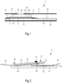
- FIG. 1 by means of a schematic diagram, an exemplary embodiment of the device for separating plasma from a whole blood sample is explained.
- a device for separating plasma from a whole blood sample generally referred to at reference numeral 1 includes a stacked structure comprised of various functional layers stacked in a parallel, overlying relationship with respect to each other.
- the device 1 is integrally formed using conventional reel-to-reel technology as detailed in the introductory portion.
- the stacked structure of the device 1 generally includes a first portion 2 and a second portion 3 in fluid communication, i.e., in contact with the first portion 2.
- the first portion 2 includes a take-up layer 4 for taking-up the blood sample made of flexible foamed material such as, but not limited to, open-cellular foamed plastic, e.g., made of melamine resin.
- the take-up layer 4 preferably is of rectangular, in particular quadratic shape having an edge length of about 10 mm and a thickness of about 1.5 mm.
- the first portion 2 further includes a depth filtration layer 5 adjacent the take-up layer 4 and in series with a plasma separation membrane 6.
- the depth filtration layer 5 is adapted to slow the flow of blood cells relative to that of the plasma in order to avoid clogging of the plasma separation membrane 6. It further enables a lateral diffusion of the blood components to thereby broaden the blood-contacted area of the plasma-separation membrane 6.
- the depth filtration layer 5 preferably is made of glass fibre material and is of rectangular, in particular quadratic shape having an edge length of about 14 mm and a thickness of about 1 mm.
- the plasma separation membrane 6 is adapted to permit plasma flow and block the passage of the cellular components of the blood, i.e. red and white blood cells and platelets. It preferably is made of porous filter material having pores adapted to capture the cellular components of the blood and preferably is of rectangular, in particular quadratic shape having an edge length of about 14 mm and a thickness of much smaller than 1 mm. In the introductory portion, the depth filtration layer 5 and the plasma separation membrane 6 together are denoted as "separating member".
- the second portion 3 includes an absorptive (wicking) layer 7 adjacent and in contact with the plasma separation membrane 6 for absorbing plasma by capillary pressure thus acting as suction pump for sucking blood through the separating member.
- the absorptive layer 7 preferably is made of porous filter paper and is of rectangular, in particular quadratic shape having an edge length of about 12 mm and a thickness of about 1 mm.
- the second portion 3 further includes a backing layer 8 adjacent the absorptive layer 7 for backing the absorptive layer 7 (film) which, e.g., can be made of stiff polyethylenterephtalate (PET) material and preferably is of rectangular, in particular quadratic shape having an edge length of about 12 mm and a thickness of about 500 ⁇ m.
- the backing layer 8 can, e.g., be provided with a recess 11 accommodating the absorptive layer 7.
- the lateral diffusion of the blood plasma caused by the depth-filtration layer 5 advantageously enables that an increased amount of plasma can be absorbed by the absorptive layer 7.
- the first portion 2 is removably fixed to the second portion 3 by a middle adhesive element 12 which, e.g., can be an adhesive layer consisting of adhesive material or may include a supporting layer provided on one or both sides with an adhesive layer made of adhesive material in such a manner that the first portion 2 can be drawn away or peeled off from the second portion 3 without destruction of the second portion 3, in particular, without destroying the absorptive layer 7. Accordingly, the first portion 2 can be removed from the second portion 3 by breaking (disconnecting) the adhesive element 12, the adhesive element 12 thus serving as predetermined breaking zone.
- a middle adhesive element 12 which, e.g., can be an adhesive layer consisting of adhesive material or may include a supporting layer provided on one or both sides with an adhesive layer made of adhesive material in such a manner that the first portion 2 can be drawn away or peeled off from the second portion 3 without destruction of the second portion 3, in particular, without destroying the absorptive layer 7. Accordingly, the first portion 2 can be removed from the second portion 3 by breaking
- the stacked structure further includes a cover layer 9 arranged on top of the stacked structure above the take-up layer 4 and a bottom layer 10 at the bottom-side of the backing layer 8, both of which can be made of non-elastic plastic materials.
- the cover layer 9 is fixed to the take-up layer 4 by an upper adhesive element 13 while the bottom layer 10 is fixed to both the backing layer 8 and the absorptive layer 7 by a lower adhesive element 14.
- the upper and lower adhesive elements 13, 14 are adhesive films made of adhesive material.
- the bottom layer 10 and the backing layer 8 together are adapted to keep the absorptive layer 7 in a predetermined position with respect to the stacked arrangement.
- the take-up layer 4 is made of an elastically compressible material and arranged in-between the cover layer 9 and the depth filtration layer 5 in a (pre-) compressed condition so that the non-elastic cover layer 9 and the non-elastic bottom layer 10 fixed to the cover layer 9 together take up the elastic (de-)compression force of the take-up layer 4.
- the depth filtration layer 5 is provided with a depth filtration layer surface 16 for receiving blood from the take-up layer 4 which is in close contact with full fit for fluid communication between the depth filtration layer 5 and the take-up layer 4.
- the plasma separation membrane 6 is provided with a plasma separation membrane surface 17 for receiving blood from the depth filtration layer 16 which is in close contact with full fit for fluid communication between the plasma separation membrane 6 and the depth filtration layer 5.
- the absorptive layer 7 is provided with an absorptive layer surface 18 for receiving plasma from the plasma separation membrane 6 which is in close contact with full fit for fluid communication between the absorptive layer 7 and the plasma separation membrane 6. Otherwise, the take-up layer 4 is provided with a take-up layer surface 15 for applying whole blood through an opening 19 of the cover layer 9. Accordingly, an intense capillary force can act on the blood sample applied on the take-up layer surface 15 to draw it through the depth filtration layer 5 and the plasma separation membrane 6 for plasma separation and absorption in the absorptive layer 7.
- the absorptive layer 7 Since the absorptive layer 7 has a plasma capacity which is less than the amount of plasma in the blood volume contained in the separating member comprised of the depth filtration layer 5 and the plasma separation membrane 6, the absorptive layer 7 becomes saturated with a predetermined amount of plasma when drawing at least a portion or all of the plasma contained in the separating member into the absorptive layer 7.
- the separating member preferably contains a plasma-soluble dye so as to signalize a plasma-saturated condition of the absorptive layer 7.
- a process for separating plasma from a blood sample starts with applying the whole blood on the take-up layer surface 15, e.g., in pricking a patient's finger and tipping onto the take-up layer surface 15 until a predetermined volume of the blood of, say, 150 ⁇ l is soaked into the take-up layer 4.
- the absorptive layer 7 After waiting for a predetermined time span of, e.g., a few minutes, it is checked whether the absorptive layer 7 is completely filled (saturated) with plasma, e.g., using a plasma-soluble dye as-above detailed. Upon reaching plasma saturation, the second portion 3 is peeled off from the first portion 2 in a wet condition of the absorptive layer 7 so as to separate the absorptive layer 7 from the separating member comprised of the depth filtration layer 5 and the plasma separation membrane 6.
- the absorptive layer 7 is dried for a predetermined time interval of, e.g., a few hours.
- a humidity detector (not illustrated) which is operatively coupled to the absorptive layer 7 can be used to detect humidity of the absorptive layer 7 for outputting at least two optical and/or acoustical signals which are different with respect to each other in response to a detection result, wherein a first signal signifies a dried condition and a second signal a wet condition of the absorptive layer 7.
- the second portion 3 including the dried absorptive layer 7 backed by the backing layer 8 can be packaged, preferably as card or vial on desiccant for shipping at room temperatures to a specific analysis site for plasma analysis.
- the backing layer 8 preferably is provided with a machine-readable label such as a barcode which advantageously allows for an easy, quick and cost-effective identification at the analysis site.
- the machine-readable label can, e.g., be disposed on a back-side of the backing layer 8, i.e., on a lower backing layer surface of the backing layer 8.
- the dried plasma is dissolved and diluted in an elution medium to perform specific tests which can be related to substances which are characteristic of specific infections such as HIV particles, e.g., involving the use of the polymerase chain reaction (PCR) or any other technique of the nucleic acid amplification type.
- the backing layer 8 can be made of a material which can be dissolved in the elution medium eliminating a risk of clotting in pipetting operations.
- FIG. 2 is a schematic sectional view another exemplary embodiment of the device 1 according to the invention is explained.
- Fig. 1 is a schematic sectional view another exemplary embodiment of the device 1 according to the invention.
- the second portion 3 is a structural entity comprised of a solid inert backing layer 8 wherein the absorptive layer 7 is arranged on an upper backing layer surface 20 of the backing layer 8.
- the absorptive layer 7 is removably fixed to the upper backing layer surface 20 of the backing layer 8 by a first adhesive spot 21, e.g., made of a brittle glue arranged in a middle portion of the absorptive layer 7 so that the absorptive layer is partly fixed to the backing layer 8 having non-fixed end region.
- the first adhesive spot 21 is denoted as second adhesive element.
- a second handle 24 is fixed to the absorptive layer 7 at an (non-fixed) edge region thereof so that the absorptive layer 7 can be readily removed from the backing layer 8 by manually gripping the second handle 24. While not shown in Fig. 2 , only the end-region of the absorptive layer 7 connected to the second handle 24 can be non-fixed to the backing layer 8 while the other end-region is fixed to the backing layer 8 by means of the first adhesive spot 21.
- the first portion 2 is a structural entity comprising the depth filtration layer 5 and the plasma separation membrane 6. While not shown in FIG. 2 , the first portion 2 may also include the take-up layer 4.
- the first portion 2 is removably fixed to the backing layer surface 20 by means of a second adhesive spot 22, e.g., made of a brittle glue at an edge region of the first portion 2.
- the second adhesive spot 21 is denoted as first adhesive element.
- both the first portion 2 and the second portion 3 are removably fixed to the upper backing layer surface 20 of the backing layer 8.
- the first portion 2 partly overlaps the second portion 3 in a region where the second portion is fixed to the backing layer 8. Accordingly, a first overlapping region 27 is formed which has a stacked configuration in which the first portion 2 is located above the second portion 3.
- the first portion 2 is arranged to enable fluid communication with the second portion 3 so that plasma can be transported from the first portion 2 to the absorptive layer 7. Accordingly, the first portion 2 or at least a part thereof is in contact with the second portion 3.
- first portion 2 or at least a part thereof can be brought in contact with the second portion 3 in such a way that plasma transfer is possible, e.g., by the pressing the first portion 2 in the direction of the backing layer 8.
- a first handle 23, opposite to the second handle 24, is fixed to the first portion 2 by means of the second adhesive spot 22 so that it can be readily removed from the backing layer 8 by manually gripping the first handle 23.
- a sample of whole blood 25 can be applied to the depth filtration layer surface 16 of the first overlapping region 27 which then is drawn through the first portion 2 to separate plasma 26 into the absorptive layer 7 by capillary pressure. Then, the first portion 2 is removed from the second portion 3 in a wet condition of the absorptive layer 7 by manual interaction at the first handle 23, followed by drying the absorptive layer 7 and shipping the second portion 3 to an analysis site in a dried condition.
- the absorptive layer 7 can be removed from the backing layer 8 by manual interaction of the second handle 24, if desired, e.g., at the analysis site facilitating plasma analysis.
- the absorptive layer 7 can, e.g., be removed from the backing layer 8 by bending the second portion 3 so that it can be helpful to have sufficient plasma-free space on both ends of the second portion 3 which allows for gripping and bending. Bending can also be reached by jamming the second portion 3 into a tube having an S-shaped inlet to thereby lose the absorptive layer 7 that can be left in the tube while removing the backing layer 8. Otherwise, the second portion 3 can have a predetermined breaking point which can be activated by inserting it in a suitable tube or, alternatively, can have a predetermined part for cutting or punching off. Obviously, the device 1 of Fig. 2 can be manufactured in a very easy and cost-effective manner in large numbers.
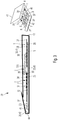
- FIG. 3 depicts a schematic sectional view and a small perspective view a yet another exemplary embodiment of the device 1 according to the invention is explained.
- Fig. 3 depicts a schematic sectional view and a small perspective view
- the device 1 includes the first portion 2 made up of the depth filtration layer 5 and the plasma separation membrane 6 and the second portion 3 made up of the absorptive layer 7, wherein both the first and second portions 2,3 are fixed to the upper backing layer surface 20 of the backing layer 8. While not shown in FIG. 3 , the first portion 2 may also include the take-up layer 4.
- the first portion 2 is fixed to the upper side of a first carrier or supporting layer 28 by means of a third adhesive spot 30 made of adhesive material such as brittle glue at an edge region of the first portion 2.
- the third adhesive spot 30 is located in a middle portion of the first supporting layer 28.
- the first supporting layer 28 is removably fixed to the upper backing layer surface 20 of the backing layer 8 by means of a peelable lower first adhesive coating 29 so that the first supporting layer 28 together with the first portion 2 can be peeled off from the backing layer 8 without destroying the absorptive layer 7, the first adhesive coating 29 thereby serving as predetermined breaking zone.
- the first supporting layer 28 which preferably is of rectangular shape extends well beyond the backing layer 8 to thereby form a first gripping portion 31 for manually gripping the first supporting layer 28.
- the first gripping portion 31 is free of the lower first adhesive coating 29. Accordingly, the lower first adhesive coating 29 covers only a part of the first supporting layer 28 so that the first supporting layer 28 can be readily peeled off from the backing layer 8.
- the second portion 3, i.e., the absorptive layer 7, is removably fixed to a second supporting layer 32 by means of a peelable upper second adhesive coating 34 made of adhesive material.
- the second supporting layer 32 is located adjacent the first supporting layer 28 leaving a small gap 36 between the first and second supporting layers 28, 32.
- the second supporting layer 32 is removably fixed to the backing layer 8 by means of a lower second adhesive coating 33 made of adhesive material so that the second supporting layer 32 together with the absorptive layer 7 can be peeled off from the backing layer 8 without destroying the absorptive layer 7, the lower second adhesive coating 33 thereby serving as predetermined breaking zone(s). Otherwise, the absorptive layer 7 can be removed from the upper second adhesive coating 34 without destroying the absorptive layer 7.
- the second supporting layer 32 which preferably is of rectangular shape extends well beyond the second portion 3 to thereby form a second gripping portion 37 for manually gripping the second supporting layer 32. While the lower second adhesive coating 33 extends beyond the second portion 3, the second gripping portion 37 is free of the second adhesive coatings 33, 34 so that the second supporting layer 32 can be readily peeled off from the backing layer 8. Accordingly, the second adhesive coatings 33, 34 cover only a part of the second supporting layer 32. While the second gripping portion 37 is in a flat position on the backing layer 8, it can be readily lift off for gripping, e.g., by means of a finger's nail.
- the first portion 2 extends towards the second portion 3 bridging the gap 36 and partly overlaps the second portion 3 in a region where the second portion 3 is fixed to the backing layer 8. Accordingly, a second overlapping region 38 is formed which has a stacked configuration in which the first portion 2 is located above the second portion 3 to be or to be brought in fluid communication (i.e. in contact) therewith so that plasma can be transported from the first portion 2 to the absorptive layer 7. Accordingly, the first portion 2 is positioned so that at least a part thereof is or can be brought into contact with the second portion 3 in such a way that plasma transfer is possible by the pressing the first portion 2 in the direction of the backing layer 8.
- an envelope 35 preferably made of paper or papercoard contains one or more devices 1. While the arrangement 39 is shown to contain three devices 1 in serial arrangement with respect to each other, those of skill in the art will appreciate that the arrangement 39 may also contain a larger or smaller number of devices 1.
- the envelope 35 includes a bottom portion 40 and a larger first top portion 41 and a smaller second top portion 42 connected to the bottom portion 40 by first and second connecting portions 43, 44, respectively, arranged in opposite relationship with respect to each other.
- the backing layer 8 is fixed to the envelope 35 by means of a fourth adhesive spot 45 made of adhesive material such as brittle glue at an edge region adjacent the second connecting portion 44 of the envelope 35.
- the first and second top portions 41, 42 can be opened or closed according to the specific demands of the user, e.g., by bending the connecting portions 43, 44, wherein in closed positions the top portions 41, 42 overlap each other so that the envelope 35 fully covers the devices 1. Stated more particularly, the larger first top portion 41 covers a major part of the devices 1 including the second overlapping region 38. Otherwise, the smaller second top portion 42 covers a minor part of the devices 1 including the second gripping portion 37.
- a sample of whole blood can be applied to the depth filtration layer surface 16 of the second overlapping region 38 of one or more devices 1.
- the blood is then drawn through the first portion 2 into the absorptive layer 7 by capillary pressure.
- the first portion 2 is removed from the second portion 3 in a wet condition of the absorptive layer 7 by manual interaction at the first gripping portion 31, followed by drying the absorptive layer 7 and shipping the arrangement 39 having the larger first top portion 41 in closed position to an analysis site in a dried condition.
- the absorptive layer 7 can be readily removed from the backing layer 8 by manual interaction at the second gripping portion 37 facilitating plasma analysis.
- the second gripping portion 37 is advantageously hide by the smaller first top portion 41 in closed position when applying the blood sample so that inadvertent manual gripping of the second gripping portion 37, e.g., by non-professional (non-medical) users can be avoided. Otherwise, the arrangement 39 can be safely shipped to the analysis site having the first and second top portions 41, 42 in closed positions to avoid contamination.
- the smaller second top portion 42 is opened to unhide the second gripping portion by professional (medical) users for manual gripping so as to remove the absorptive layer 7 from the backing layer 8.
Claims (13)
- Vorrichtung (1) zum Abtrennen von Plasma (26) aus einer Blutprobe (25), wobei die Blutprobe ein Teilvolumen von Plasma und ein Teilvolumen zellulärer Bestandteile aufweist, wobei die Vorrichtung das Folgende umfasst:einen ersten Abschnitt (2) mit einem Trennelement (5, 6) mit einer ersten Oberfläche (16) zum Auftragen oder Empfangen der Blutprobe (25), wobei das Trennelement (5, 6) dazu angepasst ist, das Durchleiten von Plasma zu erlauben, aber das Durchleiten von zellulären Bestandteilen zu unterbinden,einen zweiten Abschnitt (3) mit einem saugfähigen Element (7) zum Aufsaugen von Plasma und einem Trägerelement (8), das derart angeordnet ist, dass es das saugfähige Element (7) unterstützt, wobei das saugfähige Element (7) eine zweite Oberfläche (18) in Kontakt mit dem Trennelement (5, 6) zum Aufnehmen von Plasma aufweist und dazu angepasst ist, einen Kapillardruck zu erzeugen, um Plasma vom Trennelement (5, 6) zum saugfähigen Element (7) zu ziehen,wobei der erste Abschnitt (2) mit mindestens einem ersten Klebeelement (22; 29) derart am Trägerelement (8) befestigt ist, dass der erste Abschnitt (2) durch selektives Zerbrechen des ersten Klebeelements (22; 29) ohne Zerstörung des saugfähigen Elements (7) vom Trennelement (8) entfernt werden kann, undwobei das saugfähige Element (7) mit mindestens einem zweiten Klebeelement (21; 33) derart am Trägerelement (8) befestigt ist, dass das saugfähige Element (7) durch selektives Zerbrechen des zweiten Klebeelements (22; 29) ohne Zerstörung vom Trennelement (8) entfernt werden kann,wobei die Vorrichtung ferner Folgendes umfasst:
mindestens ein erstes Greifmittel (24; 37), das am saugfähigen Element (7) befestigt ist und zur Entfernung des saugfähigen Elements (7) vom Trägerelement (8) angepasst ist. - Vorrichtung (1) nach Anspruch 1, wobei der erste Abschnitt (2) an einer ersten Stützschicht (28), die eine Klebeschicht (29) zur Befestigung am Trägerelement (8) aufweist, befestigt ist, wobei die Klebeschicht (29) zum Abziehen der ersten Stützschicht (28) vom Trägerelement (8) angepasst ist.
- Vorrichtung (1) nach den Ansprüchen 1 oder 2, wobei das saugfähige Element (7) an einer zweiten Stützschicht (32), die eine Klebeschicht (33) zur Befestigung am Trägerelement (8) aufweist, befestigt ist, wobei die Klebeschicht (29) zum Abziehen der zweiten Stützschicht (32) vom Trägerelement (8) angepasst ist.
- Vorrichtung (1) nach Anspruch 1, wobei die ersten und zweiten Klebeelemente jeweils als Klebezone (22, 21) zur Befestigung des ersten Abschnitts (2) bzw. des saugfähigen Elements (7) am Trägerelement (8) ausgelegt sind.
- Vorrichtung (1) nach einem der vorhergehenden Ansprüche 1 bis 4, umfassend mindestens ein zweites Greifmittel (23; 31), das zur Entfernung des ersten Abschnitts (2) vom Trägerelement (8) angepasst ist.
- Vorrichtung (1) nach einem der vorhergehenden Ansprüche 1 bis 5, wobei der erste Abschnitt (2) ein Aufnahmeelement (4) mit einer dritten Oberfläche (15) zum Auftragen der Blutprobe (25) aufweist, wobei die erste Oberfläche (16) des Trennelements (5, 6) mit dem Aufnahmeelement (4) in Kontakt ist, um die Blutprobe durch einen vom saugfähigen Element (7) erzeugten Kapillardruck zu empfangen.
- Vorrichtung (1) nach einem der vorhergehenden Ansprüche 1 bis 6, umfassend ein Abdeckelement (9), das auf der Oberseite des ersten Abschnitts (2) angeordnet ist und mindestens einen Teil davon abdeckt, wobei das Abdeckelement (9) eine Öffnung (19) zum Auftragen der Blutprobe aufweist und am zweiten Abschnitt (3) und/oder einem Bodenelement (10), das an der Bodenseite des zweiten Abschnitts (3) angeordnet ist, befestigt ist.
- Vorrichtung (1) nach Anspruch 7, wobei das Aufnahmeelement (4) aus einem elastisch komprimierbaren Material gefertigt ist und zwischen dem Abdeckelement (9) und dem Trennelement (5, 6) in einem komprimierten Zustand angeordnet ist.
- Vorrichtung (1) nach einem der vorhergehenden Ansprüche 1 bis 7, wobei der zweite Abschnitt (3), insbesondere die Trägerschicht (8), ein maschinenlesbares Etikett, wie etwa einen Strichcode, aufweist.
- Vorrichtung (1) nach einem der vorhergehenden Ansprüche 1 bis 9, wobei das saugfähige Element (7) funktionsfähig mit einem Feuchtigkeitsdetektor verbunden ist, der zum Nachweisen von Feuchtigkeit des saugfähigen Elements (7) angepasst ist.
- Vorrichtung (1) nach einem der vorhergehenden Ansprüche 1 bis 10, wobei das saugfähige Element (7) aus einem Material gefertigt ist, das dazu angepasst ist, in einem Elutionsmedium zum Eluieren von getrocknetem Plasma gelöst zu werden.
- Vorrichtung (1) nach einem der vorhergehenden Ansprüche 1 bis 11, wobei das Trennelement (5, 6) einen plasmalöslichen Farbstoff enthält.
- Verfahren zum Abtrennen von Plasma aus einer Blutprobe, umfassend die folgenden Schritte:- Bereitstellen einer Vorrichtung nach einem der Ansprüche 1-12;- Auftragen der Blutprobe auf das Trennelement (5, 6), das zum Durchleiten von Plasma, aber zum Unterbinden des Durchleitens von Blutzellen angepasst ist;- Ziehen der Blutprobe durch das Trennelement (5, 6) zum saugfähigen Element (7) zum Absorbieren von Plasma mittels eines vom saugfähigen Element (7) erzeugten Kapillardrucks;- zerstörungsfreies Entfernen des ersten Abschnitts (2) vom Trägerelement (8) durch selektives Zerbrechen des ersten Klebeelements (22; 29), das den ersten Abschnitt (2) am Trägerelement (8) befestigt, ohne das saugfähige Element (7) zu zerstören;- zerstörungsfreies Entfernen des saugfähigen Elements (7) vom Trägerelement (8) durch selektives Zerbrechen eines zweiten Klebeelements (22; 29), das das saugfähige Element (7) am Trägerelement (8) befestigt, durch Verwendung mindestens eines Greifmittels (24; 37), das am saugfähigen Element (7) befestigt ist und zum Entfernen des saugfähigen Elements (7) vom Trägerelement (8) angepasst ist.
Priority Applications (1)
| Application Number | Priority Date | Filing Date | Title |
|---|---|---|---|
| EP11160450.0A EP2375249B1 (de) | 2010-04-09 | 2011-03-30 | Vorrichtungen und Verfahren zum Trennen von Plasma aus einer Blutprobe |
Applications Claiming Priority (2)
| Application Number | Priority Date | Filing Date | Title |
|---|---|---|---|
| EP10159497 | 2010-04-09 | ||
| EP11160450.0A EP2375249B1 (de) | 2010-04-09 | 2011-03-30 | Vorrichtungen und Verfahren zum Trennen von Plasma aus einer Blutprobe |
Publications (3)
| Publication Number | Publication Date |
|---|---|
| EP2375249A2 EP2375249A2 (de) | 2011-10-12 |
| EP2375249A3 EP2375249A3 (de) | 2016-12-14 |
| EP2375249B1 true EP2375249B1 (de) | 2019-12-25 |
Family
ID=42731819
Family Applications (1)
| Application Number | Title | Priority Date | Filing Date |
|---|---|---|---|
| EP11160450.0A Active EP2375249B1 (de) | 2010-04-09 | 2011-03-30 | Vorrichtungen und Verfahren zum Trennen von Plasma aus einer Blutprobe |
Country Status (2)
| Country | Link |
|---|---|
| US (1) | US20120088227A1 (de) |
| EP (1) | EP2375249B1 (de) |
Families Citing this family (12)
| Publication number | Priority date | Publication date | Assignee | Title |
|---|---|---|---|---|
| FR2982778A1 (fr) * | 2011-11-21 | 2013-05-24 | Centre Nat Rech Scient | Procede de separation membranaire en regime discontinu. |
| EP2986384B1 (de) * | 2013-04-15 | 2019-07-17 | Becton, Dickinson and Company | Übertragungsvorrichtung für die entnahme biologischer flüssigkeitsproben sowie trennungs- und testsystem für biologische flüssigkeiten |
| GB2516667A (en) * | 2013-07-29 | 2015-02-04 | Atlas Genetics Ltd | An improved cartridge, cartridge reader and method for preventing reuse |
| US10335078B2 (en) | 2014-08-04 | 2019-07-02 | General Electric Company | Device for separation and collection of plasma |
| US9950321B2 (en) * | 2014-08-04 | 2018-04-24 | General Electric Company | Device for separation and collection of plasma |
| DK3201624T3 (da) * | 2014-09-30 | 2020-06-02 | Siemens Healthcare Diagnostics Inc | Indretning til detektion af hæmolyse, system og fremgangsmåde |
| ES2903175T3 (es) * | 2015-03-31 | 2022-03-31 | Hoffmann La Roche | Tarjeta de separación de plasma |
| CN107923905B (zh) * | 2015-06-20 | 2020-05-26 | 卡皮泰奈尔公司 | 血浆分离微流体设备 |
| US20170128934A1 (en) | 2015-11-10 | 2017-05-11 | Neoteryx, Llc | Plasma extraction device |
| CN106526007B (zh) * | 2016-10-26 | 2019-10-25 | 上海万承生物科技有限公司 | 一种检测血浆活性成分方法及应用该方法的血浆卡 |
| FR3065284B1 (fr) | 2017-04-18 | 2019-06-14 | Ahlstrom-Munksjo Oyj | Nouvelle carte de collecte de plasma a partir d'un echantillon de sang |
| JP2021067491A (ja) * | 2019-10-18 | 2021-04-30 | 株式会社島津製作所 | 液体試料の処理方法および液体試料の処理装置 |
Family Cites Families (10)
| Publication number | Priority date | Publication date | Assignee | Title |
|---|---|---|---|---|
| US3666421A (en) * | 1971-04-05 | 1972-05-30 | Organon | Diagnostic test slide |
| US4839296A (en) * | 1985-10-18 | 1989-06-13 | Chem-Elec, Inc. | Blood plasma test method |
| CA2031975A1 (en) * | 1990-01-12 | 1991-07-13 | Brian R. Barkes | Device and method of separating and assaying whole blood |
| AU4766896A (en) * | 1995-02-09 | 1996-08-27 | First Medical, Inc. | Peristaltic system and method for plasma separation |
| EP0863802B1 (de) * | 1995-11-27 | 2003-04-02 | Roche Diagnostics GmbH | Element zum sammeln und transportieren von zu analyserendem probenmaterial und verfahren zur bestimmung eines analyts |
| US6106732A (en) * | 1998-04-16 | 2000-08-22 | Binax Services, Inc. | Integral blood plasma or serum isolation, metering and transport device |
| US6319719B1 (en) | 1999-10-28 | 2001-11-20 | Roche Diagnostics Corporation | Capillary hematocrit separation structure and method |
| US7569184B2 (en) * | 2002-04-23 | 2009-08-04 | Home Access Health Corporation | Quantitative analysis of a biological sample of unknown quantity |
| WO2007138614A1 (en) * | 2006-05-25 | 2007-12-06 | Arrow Coated Products Ltd | A water soluble film based matrix to collect samples extracted from living species |
| US8377379B2 (en) * | 2006-12-15 | 2013-02-19 | Kimberly-Clark Worldwide, Inc. | Lateral flow assay device |
-
2011
- 2011-03-30 EP EP11160450.0A patent/EP2375249B1/de active Active
- 2011-04-08 US US13/082,646 patent/US20120088227A1/en not_active Abandoned
Non-Patent Citations (1)
| Title |
|---|
| None * |
Also Published As
| Publication number | Publication date |
|---|---|
| EP2375249A3 (de) | 2016-12-14 |
| EP2375249A2 (de) | 2011-10-12 |
| US20120088227A1 (en) | 2012-04-12 |
Similar Documents
| Publication | Publication Date | Title |
|---|---|---|
| EP2375249B1 (de) | Vorrichtungen und Verfahren zum Trennen von Plasma aus einer Blutprobe | |
| US7407742B2 (en) | Plasma or serum separator, plasma or serum sampling method, plasma or serum separating method, test carrier and glass fiber | |
| EP1119414B1 (de) | Gerät zum sammeln biologischer proben und gebrauchsverfahren | |
| AU2015346009B2 (en) | Biological sample collection and storage assembly | |
| CN107430114B (zh) | 血浆分离卡 | |
| US20100324449A1 (en) | Blood Sampling Device Comprising At Least One Filter | |
| JP2021501340A (ja) | 液体試料採取装置 | |
| US20230398540A1 (en) | Simultaneous spot test and storage of blood samples | |
| US10675622B2 (en) | Sample collection and transfer device | |
| CN108291907B (zh) | 用于血液样品保存和红细胞比容分离的系统及方法 | |
| WO2013148071A1 (en) | Sample carrier for dried biological samples | |
| US20210018487A1 (en) | Plasma Separation Device | |
| CN113347926A (zh) | 血液样本的同时现场测试和储存 | |
| US20220257159A1 (en) | Unitary Plasma Separation Device | |
| CA2190732C (en) | Method and apparatus for the collection, storage, and real time analysisof blood and other bodily fluids |
Legal Events
| Date | Code | Title | Description |
|---|---|---|---|
| PUAI | Public reference made under article 153(3) epc to a published international application that has entered the european phase |
Free format text: ORIGINAL CODE: 0009012 |
|
| AK | Designated contracting states |
Kind code of ref document: A2 Designated state(s): AL AT BE BG CH CY CZ DE DK EE ES FI FR GB GR HR HU IE IS IT LI LT LU LV MC MK MT NL NO PL PT RO RS SE SI SK SM TR |
|
| AX | Request for extension of the european patent |
Extension state: BA ME |
|
| PUAL | Search report despatched |
Free format text: ORIGINAL CODE: 0009013 |
|
| AK | Designated contracting states |
Kind code of ref document: A3 Designated state(s): AL AT BE BG CH CY CZ DE DK EE ES FI FR GB GR HR HU IE IS IT LI LT LU LV MC MK MT NL NO PL PT RO RS SE SI SK SM TR |
|
| AX | Request for extension of the european patent |
Extension state: BA ME |
|
| RIC1 | Information provided on ipc code assigned before grant |
Ipc: G01N 33/49 20060101AFI20161104BHEP Ipc: B01L 3/00 20060101ALI20161104BHEP |
|
| STAA | Information on the status of an ep patent application or granted ep patent |
Free format text: STATUS: REQUEST FOR EXAMINATION WAS MADE |
|
| 17P | Request for examination filed |
Effective date: 20170609 |
|
| RBV | Designated contracting states (corrected) |
Designated state(s): AL AT BE BG CH CY CZ DE DK EE ES FI FR GB GR HR HU IE IS IT LI LT LU LV MC MK MT NL NO PL PT RO RS SE SI SK SM TR |
|
| GRAP | Despatch of communication of intention to grant a patent |
Free format text: ORIGINAL CODE: EPIDOSNIGR1 |
|
| STAA | Information on the status of an ep patent application or granted ep patent |
Free format text: STATUS: GRANT OF PATENT IS INTENDED |
|
| INTG | Intention to grant announced |
Effective date: 20190814 |
|
| GRAS | Grant fee paid |
Free format text: ORIGINAL CODE: EPIDOSNIGR3 |
|
| GRAA | (expected) grant |
Free format text: ORIGINAL CODE: 0009210 |
|
| STAA | Information on the status of an ep patent application or granted ep patent |
Free format text: STATUS: THE PATENT HAS BEEN GRANTED |
|
| AK | Designated contracting states |
Kind code of ref document: B1 Designated state(s): AL AT BE BG CH CY CZ DE DK EE ES FI FR GB GR HR HU IE IS IT LI LT LU LV MC MK MT NL NO PL PT RO RS SE SI SK SM TR |
|
| REG | Reference to a national code |
Ref country code: GB Ref legal event code: FG4D |
|
| REG | Reference to a national code |
Ref country code: CH Ref legal event code: EP |
|
| REG | Reference to a national code |
Ref country code: AT Ref legal event code: REF Ref document number: 1217680 Country of ref document: AT Kind code of ref document: T Effective date: 20200115 |
|
| REG | Reference to a national code |
Ref country code: DE Ref legal event code: R096 Ref document number: 602011064182 Country of ref document: DE |
|
| REG | Reference to a national code |
Ref country code: IE Ref legal event code: FG4D |
|
| REG | Reference to a national code |
Ref country code: NL Ref legal event code: MP Effective date: 20191225 |
|
| PG25 | Lapsed in a contracting state [announced via postgrant information from national office to epo] |
Ref country code: GR Free format text: LAPSE BECAUSE OF FAILURE TO SUBMIT A TRANSLATION OF THE DESCRIPTION OR TO PAY THE FEE WITHIN THE PRESCRIBED TIME-LIMIT Effective date: 20200326 Ref country code: LT Free format text: LAPSE BECAUSE OF FAILURE TO SUBMIT A TRANSLATION OF THE DESCRIPTION OR TO PAY THE FEE WITHIN THE PRESCRIBED TIME-LIMIT Effective date: 20191225 Ref country code: BG Free format text: LAPSE BECAUSE OF FAILURE TO SUBMIT A TRANSLATION OF THE DESCRIPTION OR TO PAY THE FEE WITHIN THE PRESCRIBED TIME-LIMIT Effective date: 20200325 Ref country code: FI Free format text: LAPSE BECAUSE OF FAILURE TO SUBMIT A TRANSLATION OF THE DESCRIPTION OR TO PAY THE FEE WITHIN THE PRESCRIBED TIME-LIMIT Effective date: 20191225 Ref country code: SE Free format text: LAPSE BECAUSE OF FAILURE TO SUBMIT A TRANSLATION OF THE DESCRIPTION OR TO PAY THE FEE WITHIN THE PRESCRIBED TIME-LIMIT Effective date: 20191225 Ref country code: LV Free format text: LAPSE BECAUSE OF FAILURE TO SUBMIT A TRANSLATION OF THE DESCRIPTION OR TO PAY THE FEE WITHIN THE PRESCRIBED TIME-LIMIT Effective date: 20191225 Ref country code: NO Free format text: LAPSE BECAUSE OF FAILURE TO SUBMIT A TRANSLATION OF THE DESCRIPTION OR TO PAY THE FEE WITHIN THE PRESCRIBED TIME-LIMIT Effective date: 20200325 |
|
| REG | Reference to a national code |
Ref country code: LT Ref legal event code: MG4D |
|
| PG25 | Lapsed in a contracting state [announced via postgrant information from national office to epo] |
Ref country code: HR Free format text: LAPSE BECAUSE OF FAILURE TO SUBMIT A TRANSLATION OF THE DESCRIPTION OR TO PAY THE FEE WITHIN THE PRESCRIBED TIME-LIMIT Effective date: 20191225 Ref country code: RS Free format text: LAPSE BECAUSE OF FAILURE TO SUBMIT A TRANSLATION OF THE DESCRIPTION OR TO PAY THE FEE WITHIN THE PRESCRIBED TIME-LIMIT Effective date: 20191225 |
|
| PG25 | Lapsed in a contracting state [announced via postgrant information from national office to epo] |
Ref country code: AL Free format text: LAPSE BECAUSE OF FAILURE TO SUBMIT A TRANSLATION OF THE DESCRIPTION OR TO PAY THE FEE WITHIN THE PRESCRIBED TIME-LIMIT Effective date: 20191225 |
|
| PG25 | Lapsed in a contracting state [announced via postgrant information from national office to epo] |
Ref country code: PT Free format text: LAPSE BECAUSE OF FAILURE TO SUBMIT A TRANSLATION OF THE DESCRIPTION OR TO PAY THE FEE WITHIN THE PRESCRIBED TIME-LIMIT Effective date: 20200520 Ref country code: CZ Free format text: LAPSE BECAUSE OF FAILURE TO SUBMIT A TRANSLATION OF THE DESCRIPTION OR TO PAY THE FEE WITHIN THE PRESCRIBED TIME-LIMIT Effective date: 20191225 Ref country code: NL Free format text: LAPSE BECAUSE OF FAILURE TO SUBMIT A TRANSLATION OF THE DESCRIPTION OR TO PAY THE FEE WITHIN THE PRESCRIBED TIME-LIMIT Effective date: 20191225 Ref country code: RO Free format text: LAPSE BECAUSE OF FAILURE TO SUBMIT A TRANSLATION OF THE DESCRIPTION OR TO PAY THE FEE WITHIN THE PRESCRIBED TIME-LIMIT Effective date: 20191225 Ref country code: EE Free format text: LAPSE BECAUSE OF FAILURE TO SUBMIT A TRANSLATION OF THE DESCRIPTION OR TO PAY THE FEE WITHIN THE PRESCRIBED TIME-LIMIT Effective date: 20191225 |
|
| PG25 | Lapsed in a contracting state [announced via postgrant information from national office to epo] |
Ref country code: IS Free format text: LAPSE BECAUSE OF FAILURE TO SUBMIT A TRANSLATION OF THE DESCRIPTION OR TO PAY THE FEE WITHIN THE PRESCRIBED TIME-LIMIT Effective date: 20200425 Ref country code: SM Free format text: LAPSE BECAUSE OF FAILURE TO SUBMIT A TRANSLATION OF THE DESCRIPTION OR TO PAY THE FEE WITHIN THE PRESCRIBED TIME-LIMIT Effective date: 20191225 Ref country code: SK Free format text: LAPSE BECAUSE OF FAILURE TO SUBMIT A TRANSLATION OF THE DESCRIPTION OR TO PAY THE FEE WITHIN THE PRESCRIBED TIME-LIMIT Effective date: 20191225 |
|
| REG | Reference to a national code |
Ref country code: DE Ref legal event code: R097 Ref document number: 602011064182 Country of ref document: DE |
|
| PG25 | Lapsed in a contracting state [announced via postgrant information from national office to epo] |
Ref country code: DK Free format text: LAPSE BECAUSE OF FAILURE TO SUBMIT A TRANSLATION OF THE DESCRIPTION OR TO PAY THE FEE WITHIN THE PRESCRIBED TIME-LIMIT Effective date: 20191225 Ref country code: ES Free format text: LAPSE BECAUSE OF FAILURE TO SUBMIT A TRANSLATION OF THE DESCRIPTION OR TO PAY THE FEE WITHIN THE PRESCRIBED TIME-LIMIT Effective date: 20191225 Ref country code: MC Free format text: LAPSE BECAUSE OF FAILURE TO SUBMIT A TRANSLATION OF THE DESCRIPTION OR TO PAY THE FEE WITHIN THE PRESCRIBED TIME-LIMIT Effective date: 20191225 |
|
| PLBE | No opposition filed within time limit |
Free format text: ORIGINAL CODE: 0009261 |
|
| STAA | Information on the status of an ep patent application or granted ep patent |
Free format text: STATUS: NO OPPOSITION FILED WITHIN TIME LIMIT |
|
| REG | Reference to a national code |
Ref country code: AT Ref legal event code: MK05 Ref document number: 1217680 Country of ref document: AT Kind code of ref document: T Effective date: 20191225 |
|
| PG25 | Lapsed in a contracting state [announced via postgrant information from national office to epo] |
Ref country code: SI Free format text: LAPSE BECAUSE OF FAILURE TO SUBMIT A TRANSLATION OF THE DESCRIPTION OR TO PAY THE FEE WITHIN THE PRESCRIBED TIME-LIMIT Effective date: 20191225 |
|
| 26N | No opposition filed |
Effective date: 20200928 |
|
| REG | Reference to a national code |
Ref country code: BE Ref legal event code: MM Effective date: 20200331 |
|
| PG25 | Lapsed in a contracting state [announced via postgrant information from national office to epo] |
Ref country code: LU Free format text: LAPSE BECAUSE OF NON-PAYMENT OF DUE FEES Effective date: 20200330 |
|
| PG25 | Lapsed in a contracting state [announced via postgrant information from national office to epo] |
Ref country code: IE Free format text: LAPSE BECAUSE OF NON-PAYMENT OF DUE FEES Effective date: 20200330 Ref country code: IT Free format text: LAPSE BECAUSE OF FAILURE TO SUBMIT A TRANSLATION OF THE DESCRIPTION OR TO PAY THE FEE WITHIN THE PRESCRIBED TIME-LIMIT Effective date: 20191225 Ref country code: AT Free format text: LAPSE BECAUSE OF FAILURE TO SUBMIT A TRANSLATION OF THE DESCRIPTION OR TO PAY THE FEE WITHIN THE PRESCRIBED TIME-LIMIT Effective date: 20191225 |
|
| PG25 | Lapsed in a contracting state [announced via postgrant information from national office to epo] |
Ref country code: BE Free format text: LAPSE BECAUSE OF NON-PAYMENT OF DUE FEES Effective date: 20200331 Ref country code: PL Free format text: LAPSE BECAUSE OF FAILURE TO SUBMIT A TRANSLATION OF THE DESCRIPTION OR TO PAY THE FEE WITHIN THE PRESCRIBED TIME-LIMIT Effective date: 20191225 |
|
| PG25 | Lapsed in a contracting state [announced via postgrant information from national office to epo] |
Ref country code: TR Free format text: LAPSE BECAUSE OF FAILURE TO SUBMIT A TRANSLATION OF THE DESCRIPTION OR TO PAY THE FEE WITHIN THE PRESCRIBED TIME-LIMIT Effective date: 20191225 Ref country code: MT Free format text: LAPSE BECAUSE OF FAILURE TO SUBMIT A TRANSLATION OF THE DESCRIPTION OR TO PAY THE FEE WITHIN THE PRESCRIBED TIME-LIMIT Effective date: 20191225 Ref country code: CY Free format text: LAPSE BECAUSE OF FAILURE TO SUBMIT A TRANSLATION OF THE DESCRIPTION OR TO PAY THE FEE WITHIN THE PRESCRIBED TIME-LIMIT Effective date: 20191225 |
|
| PG25 | Lapsed in a contracting state [announced via postgrant information from national office to epo] |
Ref country code: MK Free format text: LAPSE BECAUSE OF FAILURE TO SUBMIT A TRANSLATION OF THE DESCRIPTION OR TO PAY THE FEE WITHIN THE PRESCRIBED TIME-LIMIT Effective date: 20191225 |
|
| PGFP | Annual fee paid to national office [announced via postgrant information from national office to epo] |
Ref country code: FR Payment date: 20230209 Year of fee payment: 13 |
|
| PGFP | Annual fee paid to national office [announced via postgrant information from national office to epo] |
Ref country code: CH Payment date: 20230401 Year of fee payment: 13 |
|
| PGFP | Annual fee paid to national office [announced via postgrant information from national office to epo] |
Ref country code: DE Payment date: 20240220 Year of fee payment: 14 Ref country code: GB Payment date: 20240220 Year of fee payment: 14 |