EP2375202A1 - Method for making a refrigerating cell and refrigerating device comprising the refrigerating cell - Google Patents
Method for making a refrigerating cell and refrigerating device comprising the refrigerating cell Download PDFInfo
- Publication number
- EP2375202A1 EP2375202A1 EP11161376A EP11161376A EP2375202A1 EP 2375202 A1 EP2375202 A1 EP 2375202A1 EP 11161376 A EP11161376 A EP 11161376A EP 11161376 A EP11161376 A EP 11161376A EP 2375202 A1 EP2375202 A1 EP 2375202A1
- Authority
- EP
- European Patent Office
- Prior art keywords
- making
- enclosure
- hole
- reference means
- visual reference
- Prior art date
- Legal status (The legal status is an assumption and is not a legal conclusion. Google has not performed a legal analysis and makes no representation as to the accuracy of the status listed.)
- Granted
Links
- 238000000034 method Methods 0.000 title claims abstract description 29
- 230000000007 visual effect Effects 0.000 claims abstract description 47
- 235000013305 food Nutrition 0.000 claims abstract description 16
- 239000000463 material Substances 0.000 claims description 6
- 238000003754 machining Methods 0.000 claims description 5
- 238000005520 cutting process Methods 0.000 claims description 3
- 229920005669 high impact polystyrene Polymers 0.000 description 3
- 239000004797 high-impact polystyrene Substances 0.000 description 3
- 238000004519 manufacturing process Methods 0.000 description 3
- 239000004033 plastic Substances 0.000 description 2
- 239000000047 product Substances 0.000 description 2
- 239000007795 chemical reaction product Substances 0.000 description 1
- 230000007547 defect Effects 0.000 description 1
- 230000002950 deficient Effects 0.000 description 1
- 238000009429 electrical wiring Methods 0.000 description 1
- -1 for example Substances 0.000 description 1
- 239000011159 matrix material Substances 0.000 description 1
- 238000003856 thermoforming Methods 0.000 description 1
Images


Classifications
-
- F—MECHANICAL ENGINEERING; LIGHTING; HEATING; WEAPONS; BLASTING
- F25—REFRIGERATION OR COOLING; COMBINED HEATING AND REFRIGERATION SYSTEMS; HEAT PUMP SYSTEMS; MANUFACTURE OR STORAGE OF ICE; LIQUEFACTION SOLIDIFICATION OF GASES
- F25D—REFRIGERATORS; COLD ROOMS; ICE-BOXES; COOLING OR FREEZING APPARATUS NOT OTHERWISE PROVIDED FOR
- F25D23/00—General constructional features
- F25D23/06—Walls
- F25D23/065—Details
- F25D23/066—Liners
Definitions
- This invention relates to a method for making a refrigerating cell and a device for refrigerating and storing food products and comprising the refrigerating cell.
- Refrigerating cells normally comprise a thermoformed enclosure made by die forming and delimiting a zone for storing food products.
- a plurality of openings are then made in the enclosure to allow connection of refrigerated air conduits (for example in the case of a no-frost refrigerator) or for the passage of electrical wiring.
- These openings are holes which are usually made in the die formed enclosure by numerical control machines.
- the enclosure can then be sent to the assembly line.
- some of the enclosures are unexpectedly found not to have the openings in the required number or at the required positions (this may be due to errors positioning an enclosure relative to the numerical control machine or to a human error during programming of the numerical control machine). This may make it impossible to assemble the enclosure or create problems connected with the quality of the end product.
- the technical purpose which forms the basis of this invention is to propose a method for making a refrigerating cell and a refrigerating device for refrigerating and storing food products and comprising the refrigerating cell that overcome the above mentioned disadvantages of the prior art.
- this invention has for an aim to provide a method and a device which can speed up assembly in the production line.
- Another aim of the invention is to propose method which can improve product quality.
- a further aim of the invention is to propose a method which can facilitate the task of checking the work of a human operator.
- a further aim of the invention is to propose a method which can facilitate the performance of some of the steps in the method for making the refrigerating cell.
- the object of this invention is a method for making a refrigerating cell 1 comprising an enclosure 2 whose walls 20 delimit at least partially a zone 200 for storing food products.
- the enclosure 2 has an opening 23 giving access to the zone 200 for storing food products, the opening 23 being designed to be closed by a door.
- the enclosure 2 comprises a lower base 24 and a ceiling 25 opposite the lower base 24.
- the enclosure 2 also comprises two side walls 26 and an end wall 27 which are interposed between the base 24 and the ceiling 25.
- the end wall 27 is located opposite the opening 23 which is designed to be closed by a door.
- refrigerating cell is meant a cell designed to refrigerate and store food products at any temperature.
- the term "refrigerating cell” may denote both a cell designed to be used as a refrigerator compartment and a cell designed to be used as a freezer compartment.
- the method comprises the step of making by die forming (preferably by thermoforming) the walls 20 of the enclosure 2.
- the enclosure 2 is made of plastic material, preferably HIPS.
- the method subsequently comprises a step of making at least one through hole 21 passing through at least one of the walls 20 of the enclosure 2.
- the hole 21 might be made using a cutting tool such as a routing bit or a die and matrix (in the latter case, the process is known as blanking).
- the step of die forming the walls 20 of the enclosure 2 comprises also making by die forming visual reference means 3 that identify a first zone 22 where the through hole 21 is made (during the step of making at least one through 21 which passes through at least one of the walls 20 of the enclosure 2).
- the step of making the visual reference means 3 is thus simultaneous with the step of die forming the rest of the walls 20 of the enclosure 2.
- the through hole 21 is not made simultaneously with the step of die forming the rest of the enclosure 2 since that would create problems extracting the enclosure 2 from the mould.
- the step of making by die forming the visual reference means 3 comprises making the visual reference means 3 as a single part with the rest of the enclosure 2.
- the step of making by die forming the visual reference means 3 comprises making by die forming one or more irregularities on the walls 20 of the enclosure 2.
- the step of making by die forming the visual reference means 3 comprises the step of making by die forming at least one protrusion 30 or one groove forming part of the visual reference means 3 (meaning that the above mentioned irregularities may comprise the protrusions 30 or the grooves).
- the step of making at least one hole 21 is performed by numerical control machines or manually.
- the step of making at least one through hole 21 is preceded by the step of positioning a cutting tool relative to the first zone 22 with the aid of the visual reference means 3.
- the step of making at least one through hole 21 involves locating the hole 21 at a minimum distance of less than 1 millimetre (advantageously at a minimum distance of between 0.4 and 0.6 millimetres and preferably at a minimum distance of between 0.45 and 0.55 millimetres) from each single visual reference 3a, 3b, 3c, 3d forming part of the visual reference means 3.
- the step of making by die forming the visual reference means 3 comprises making the visual reference means 3 at least on the end wall 27.
- the step of making by die forming the visual reference means 3 comprises/coincides with the step of making by die forming at least four protrusions 30 or grooves forming part of the visual reference means 3 (alternatively, at least two protrusions 30 or grooves might be made by die forming - this embodiment not being illustrated).
- the step of making by die forming the visual reference means 3 coincides with the step of making by die forming a protrusion 30 or groove which surrounds the entire first zone. In the latter case, the protrusion 30 or groove is advantageously made on the end wall 27.
- the step of making by die forming the visual reference means 3 comprises making at least one, advantageously a plurality, preferably all the protrusions 30 or grooves, with two intersecting sections that meet at a common zone (this makes it easier for the user to identify the first zone 22).
- the method comprises the step of selecting the enclosure 2 where the through hole is at least partially outside the first zone 22 identified by the visual reference means 3.
- the method comprises examining the enclosure 2 to decide whether to reject it, use it without further removal of material or subject it to further removal of material.
- the enclosure 2 might be rejected if the first zone 22 is well outside the zone delimited by the visual reference means 3.
- the enclosure 2 is reused as far as possible, although further machining is sometimes necessary. Thanks to the invention, the user immediately notices any defects in the enclosure 2. This may have the added advantage that defective enclosures 2 are not sent to the assembly line and thus do not slow down the assembly line.
- the step of making the at least one through hole 21 is carried out at a first machining centre.
- the method comprises the steps of:
- the step of making at least one through hole 21 passing through at least one of the walls 20 of the enclosure 2 is carried out by a numerical control machine after positioning the enclosure 2 relative to the machine.
- This invention also has for an object a refrigerating device for refrigerating and storing food products and comprising a refrigerating cell 1 comprising an enclosure 2 in turn comprising walls 20 which identify a zone 200 for storing food products.
- the enclosure 2 is made of plastic material such as, for example, HIPS (high impact polystyrene). At least one of the walls 20 has a hole 21 which goes right through the thickness of it.
- the enclosure 2 has an opening 23 giving access to the zone 200 for storing food products; the opening 23 being closable by a door forming part of the device 1.
- walls 20 of the enclosure 2 comprise a lower base 24 and a ceiling 25 opposite the lower base 24.
- at least one hole 21 is made in the ceiling 25 of the enclosure 2.
- the walls 20 of the enclosure 2 also comprise two side walls 26 and an end wall 27 which are interposed between the base 24 and the ceiling 25.
- the end wall 27 is located opposite the opening 23 which is designed to be closed by a door.
- at least one hole 21 is made in the end wall 27 of the enclosure 2.
- the device 1 comprises visual reference means 3 which identify a first zone 22 where the hole 21 is made.
- the visual reference means 3 and the hole 21 are made at least in the end wall 27 of the enclosure 2.
- the visual reference means 3 extend along an imaginary line that surrounds the through hole 21.
- the visual reference means 3 are made as one with the enclosure 2.
- the visual reference means 3 comprise one or more irregularities on the surface of the enclosure 2. More specifically, an irregularity may be a groove or a protrusion. Conveniently, at least one, advantageously a plurality, preferably all the protrusions or grooves comprise two intersecting sections that meet at a common zone, the two sections extending along two corresponding edges of the hole 21 (provided always that the hole 21 has been made correctly). Advantageously, if the hole 21 has an edge whose sides are oriented at 90° to each other, the two sections of the above mentioned grooves are also oriented at 90°.
- the hole 21 is quadrilateral and the visual reference means 3 comprise four protrusions 30 or four grooves located at the four corners of the quadrilateral formed by the hole 21.
- the visual reference means 3 might comprise a single protrusion or groove surrounding the entire hole 22.
- the hole 21 might be quadrilateral and the visual reference means 3 might comprise two protrusions or grooves located at two opposite corners of the perimeter of the hole 21.
- the visual reference means 3 comprise a first and a second reference 3a, 3b, separate from each other, the minimum distance of the first and the second reference 3a, 3b from the hole 21 being less than 1 millimetre.
- the first and second references 3a, 3b form part of the protrusions 30 or grooves.
- the visual reference means 3 comprise a plurality of separate references 3a, 3b, 3c, 3d, the minimum distance of each of the references 3a, 3b from the hole 21 being less than 1 millimetre (advantageously, the minimum distance being between 0.4 and 0.6 millimetres and preferably the minimum distance being between 0.45 and 0.55 millimetres).
- This invention has important advantages. In particular, it allows product quality to be improved. Also, it allows assembly in the production line to be speeded up since only enclosures suitable for assembly reach the production line or, in any case, any unsuitable enclosures can be identified immediately and immediately rejected even in the assembly line.
Landscapes
- Engineering & Computer Science (AREA)
- Chemical & Material Sciences (AREA)
- Combustion & Propulsion (AREA)
- Physics & Mathematics (AREA)
- Mechanical Engineering (AREA)
- Thermal Sciences (AREA)
- General Engineering & Computer Science (AREA)
- Devices That Are Associated With Refrigeration Equipment (AREA)
Abstract
-making the walls (20) of the enclosure (2) by die forming;
-making at least one through hole (21) passing through at least one of the walls (20) of the enclosure (2).
The step of making the walls (20) of the enclosure (2) by die forming comprises making by die forming visual reference means (3) that identify a first zone (22) where the through hole (21) is made.
Description
- This invention relates to a method for making a refrigerating cell and a device for refrigerating and storing food products and comprising the refrigerating cell.
- Refrigerating cells normally comprise a thermoformed enclosure made by die forming and delimiting a zone for storing food products.
- A plurality of openings are then made in the enclosure to allow connection of refrigerated air conduits (for example in the case of a no-frost refrigerator) or for the passage of electrical wiring.
- These openings are holes which are usually made in the die formed enclosure by numerical control machines.
- The enclosure can then be sent to the assembly line. At the assembly line, some of the enclosures are unexpectedly found not to have the openings in the required number or at the required positions (this may be due to errors positioning an enclosure relative to the numerical control machine or to a human error during programming of the numerical control machine). This may make it impossible to assemble the enclosure or create problems connected with the quality of the end product.
- In this context, the technical purpose which forms the basis of this invention is to propose a method for making a refrigerating cell and a refrigerating device for refrigerating and storing food products and comprising the refrigerating cell that overcome the above mentioned disadvantages of the prior art.
- In particular, this invention has for an aim to provide a method and a device which can speed up assembly in the production line.
- Another aim of the invention is to propose method which can improve product quality.
- A further aim of the invention is to propose a method which can facilitate the task of checking the work of a human operator.
- A further aim of the invention is to propose a method which can facilitate the performance of some of the steps in the method for making the refrigerating cell.
- The technical purpose and aims specified are substantially achieved by a method for making a refrigerating cell and a refrigerating device for refrigerating and storing food products and comprising the technical features described in one or more of the appended claims.
- Further features and advantages of the invention are more apparent in the non-limiting description which follows of a preferred non-limiting embodiment of a method for making a refrigerating cell and a refrigerating device for refrigerating and storing food products as illustrated in the accompanying drawings, in which:
-
Figures 1 and 2 show an enclosure of the type described in this specification, before and after an operation of making holes in it, respectively; -
Figure 3 shows the enclosure ofFigure 1 from another perspective; -
Figure 4 shows the enclosure ofFigure 2 from another perspective; -
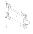
Figure 5 shows a detail of an enclosure described in this specification. - The object of this invention is a method for making a refrigerating cell 1 comprising an
enclosure 2 whosewalls 20 delimit at least partially azone 200 for storing food products. Theenclosure 2 has an opening 23 giving access to thezone 200 for storing food products, the opening 23 being designed to be closed by a door. - Advantageously, the
enclosure 2 comprises alower base 24 and aceiling 25 opposite thelower base 24. Theenclosure 2 also comprises twoside walls 26 and anend wall 27 which are interposed between thebase 24 and theceiling 25. Theend wall 27 is located opposite the opening 23 which is designed to be closed by a door. - By refrigerating cell is meant a cell designed to refrigerate and store food products at any temperature. For example, the term "refrigerating cell" may denote both a cell designed to be used as a refrigerator compartment and a cell designed to be used as a freezer compartment. The method comprises the step of making by die forming (preferably by thermoforming) the
walls 20 of theenclosure 2. Advantageously, theenclosure 2 is made of plastic material, preferably HIPS. - The method subsequently comprises a step of making at least one through hole 21 passing through at least one of the
walls 20 of theenclosure 2. For example, the hole 21 might be made using a cutting tool such as a routing bit or a die and matrix (in the latter case, the process is known as blanking). - The step of die forming the
walls 20 of theenclosure 2 comprises also making by die forming visual reference means 3 that identify a first zone 22 where the through hole 21 is made (during the step of making at least one through 21 which passes through at least one of thewalls 20 of the enclosure 2). The step of making the visual reference means 3 is thus simultaneous with the step of die forming the rest of thewalls 20 of theenclosure 2. - The through hole 21 is not made simultaneously with the step of die forming the rest of the
enclosure 2 since that would create problems extracting theenclosure 2 from the mould. The step of making by die forming the visual reference means 3 comprises making the visual reference means 3 as a single part with the rest of theenclosure 2. - The step of making by die forming the visual reference means 3 comprises making by die forming one or more irregularities on the
walls 20 of theenclosure 2. - The step of making by die forming the visual reference means 3 comprises the step of making by die forming at least one
protrusion 30 or one groove forming part of the visual reference means 3 (meaning that the above mentioned irregularities may comprise theprotrusions 30 or the grooves). - The step of making at least one hole 21 is performed by numerical control machines or manually. In the latter case, advantageously, the step of making at least one through hole 21 is preceded by the step of positioning a cutting tool relative to the first zone 22 with the aid of the visual reference means 3.
- The step of making at least one through hole 21 involves locating the hole 21 at a minimum distance of less than 1 millimetre (advantageously at a minimum distance of between 0.4 and 0.6 millimetres and preferably at a minimum distance of between 0.45 and 0.55 millimetres) from each single
visual reference 3a, 3b, 3c, 3d forming part of the visual reference means 3. Conveniently, the step of making by die forming the visual reference means 3 comprises making the visual reference means 3 at least on theend wall 27. - With reference to the embodiment of
Figure 5 , the step of making by die forming the visual reference means 3 comprises/coincides with the step of making by die forming at least fourprotrusions 30 or grooves forming part of the visual reference means 3 (alternatively, at least twoprotrusions 30 or grooves might be made by die forming - this embodiment not being illustrated). In another embodiment, not illustrated, the step of making by die forming the visual reference means 3 coincides with the step of making by die forming aprotrusion 30 or groove which surrounds the entire first zone. In the latter case, theprotrusion 30 or groove is advantageously made on theend wall 27. - The step of making by die forming the visual reference means 3 comprises making at least one, advantageously a plurality, preferably all the
protrusions 30 or grooves, with two intersecting sections that meet at a common zone (this makes it easier for the user to identify the first zone 22). - After obtaining the
enclosure 2 it is important, for the quality of the finished cell 1, to select (or more specifically, separate) theenclosures 2 which have imperfections (in order to assess appropriate solutions). - In this regard, the method comprises the step of selecting the
enclosure 2 where the through hole is at least partially outside the first zone 22 identified by the visual reference means 3. - After selection, the method comprises examining the
enclosure 2 to decide whether to reject it, use it without further removal of material or subject it to further removal of material. For example, theenclosure 2 might be rejected if the first zone 22 is well outside the zone delimited by the visual reference means 3. Normally, theenclosure 2 is reused as far as possible, although further machining is sometimes necessary. Thanks to the invention, the user immediately notices any defects in theenclosure 2. This may have the added advantage thatdefective enclosures 2 are not sent to the assembly line and thus do not slow down the assembly line. - The step of making the at least one through hole 21 is carried out at a first machining centre. In this regard, the method comprises the steps of:
- selecting an
enclosure 2 that has passed through the first machining centre and where there is no hole 21 inside the first zone 22 identified by the visual reference means 3 or where the hole 21 is at least partly outside the first zone 21 identified by the visual reference means 3. - making a through hole 21 in the first zone 22.
- Advantageously, the step of making at least one through hole 21 passing through at least one of the
walls 20 of theenclosure 2 is carried out by a numerical control machine after positioning theenclosure 2 relative to the machine. - This invention also has for an object a refrigerating device for refrigerating and storing food products and comprising a refrigerating cell 1 comprising an
enclosure 2 inturn comprising walls 20 which identify azone 200 for storing food products. Advantageously, theenclosure 2 is made of plastic material such as, for example, HIPS (high impact polystyrene). At least one of thewalls 20 has a hole 21 which goes right through the thickness of it. - The
enclosure 2 has an opening 23 giving access to thezone 200 for storing food products; the opening 23 being closable by a door forming part of the device 1. - Advantageously,
walls 20 of theenclosure 2 comprise alower base 24 and aceiling 25 opposite thelower base 24. By way of an example, at least one hole 21 is made in theceiling 25 of theenclosure 2. Thewalls 20 of theenclosure 2 also comprise twoside walls 26 and anend wall 27 which are interposed between thebase 24 and theceiling 25. Theend wall 27 is located opposite the opening 23 which is designed to be closed by a door. Advantageously, at least one hole 21 is made in theend wall 27 of theenclosure 2. - The device 1 comprises visual reference means 3 which identify a first zone 22 where the hole 21 is made.
- Advantageously, the visual reference means 3 and the hole 21 are made at least in the
end wall 27 of theenclosure 2. - The visual reference means 3 extend along an imaginary line that surrounds the through hole 21. The visual reference means 3 are made as one with the
enclosure 2. - Advantageously, the visual reference means 3 comprise one or more irregularities on the surface of the
enclosure 2. More specifically, an irregularity may be a groove or a protrusion. Conveniently, at least one, advantageously a plurality, preferably all the protrusions or grooves comprise two intersecting sections that meet at a common zone, the two sections extending along two corresponding edges of the hole 21 (provided always that the hole 21 has been made correctly). Advantageously, if the hole 21 has an edge whose sides are oriented at 90° to each other, the two sections of the above mentioned grooves are also oriented at 90°. - Advantageously, the hole 21 is quadrilateral and the visual reference means 3 comprise four
protrusions 30 or four grooves located at the four corners of the quadrilateral formed by the hole 21. - Alternatively, the visual reference means 3 might comprise a single protrusion or groove surrounding the entire hole 22. In another embodiment, the hole 21 might be quadrilateral and the visual reference means 3 might comprise two protrusions or grooves located at two opposite corners of the perimeter of the hole 21.
- The visual reference means 3 comprise a first and a second reference 3a, 3b, separate from each other, the minimum distance of the first and the second reference 3a, 3b from the hole 21 being less than 1 millimetre. Advantageously, the first and second references 3a, 3b form part of the
protrusions 30 or grooves. Preferably, the visual reference means 3 comprise a plurality ofseparate references 3a, 3b, 3c, 3d, the minimum distance of each of the references 3a, 3b from the hole 21 being less than 1 millimetre (advantageously, the minimum distance being between 0.4 and 0.6 millimetres and preferably the minimum distance being between 0.45 and 0.55 millimetres). - This invention has important advantages. In particular, it allows product quality to be improved. Also, it allows assembly in the production line to be speeded up since only enclosures suitable for assembly reach the production line or, in any case, any unsuitable enclosures can be identified immediately and immediately rejected even in the assembly line.
- It shall be understood that the invention described above may be modified and adapted in several ways without departing from the scope of the inventive concept. Moreover, all the details of the invention may be substituted by other technically equivalent elements. Further, the embodiments of the invention may be made in any size, depending on requirements.
Claims (12)
- A method for making a refrigerating cell (1) comprising an enclosure (2) whose walls (20) delimit at least partially a zone (200) for storing food products, the method comprising the steps of:- making the walls (20) of the enclosure (2) by die forming;- making at least one through hole (21) passing through at least one of the walls (20) of the enclosure (2);characterized in that the step of making the walls (20) of the enclosure (2) by die forming comprises making by die forming visual reference means (3) that identify a first zone (22) where the through hole (21) is made.
- The method according to claim 1, characterized in that the step of making by die forming the visual reference means (3) comprises making the visual reference means (3) as a single part with the remaining parts of the enclosure (2).
- The method according to claim 1 or 2, characterized in that the step of making by die forming the visual reference means (3) comprises the step of making by die forming at least one protrusion (30) or one groove forming part of the visual reference means (3).
- The method according to any of the foregoing claims, characterized in that the step of making by die forming the visual reference means (3) coincides with the step of making by die forming four protrusions (30) or grooves forming part of the visual reference means (3).
- The method according to any of the foregoing claims, characterized in that the step of making at least one through hole (21) is preceded by the step of positioning a cutting tool relative to the first zone (22) with the aid of the visual reference means (3).
- The method according to any of the foregoing claims, characterized by:- selecting the enclosure (2) where the through hole is at least partially outside the first zone (22) identified by the visual reference means (3);- examining the enclosure (2) to decide whether to reject it, use it without further removal of material or subject it to further removal of material.
- The method according to any of the foregoing claims, characterized in that the step of making the at least one through hole (21) is carried out at a first machining centre, the method comprising the steps of:- selecting an enclosure (2) that has passed through the first machining centre and where there is no hole (21) inside the first zone (22) identified by the visual reference means (3) or where the hole (21) is at least partly outside the first zone (22) identified by the visual reference means (3);- making a through hole (21) in the first zone (22).
- The method according to any of the foregoing claims, characterized in that the step of making at least one through hole (21) passing through at least one of the walls (20) of the enclosure (2) is carried out by a numeric control machine after positioning the enclosure (2) relative to the machine.
- A device for refrigerating and storing food products comprising a refrigerating cell (1) comprising an enclosure (2) in turn comprising walls (20) which delimit a zone (200) for storing food products, at least one of the walls (20) having a hole (21) passing through it all the way, characterized in that it comprises visual reference means (3) which identify a first zone (22) where the hole (21) is made, the visual reference means (3) being made as a single part with the enclosure (2).
- The device according to claim 9, characterized in that the hole (21) is quadrilateral and the visual reference means (3) comprise four protrusions (30) or grooves located at the four corners of the quadrilateral formed by the hole (21).
- The device according to claim 9 or 10, characterized in that the visual reference means (3) comprise at least a first and a second reference (3a, 3b), the minimum distance of the first and the second reference (3a, 3b) from the hole (21) being less than 1 millimetre.
- The device according to claim 9 or 10 or 11, characterised in that the walls (20) of the enclosure (2) comprise:- a lower base (24);- a ceiling (25) opposite the lower base (24);- two side walls (26) and an end wall (27) which are interposed between the base (24) and the ceiling (25), the end wall (27) being opposite an opening (23) giving access to the zone (200) for storing food products, the opening (23) being closable by a door forming part of the device (1);the visual reference means (3) and the hole (21) being made at least on the end wall (27).
Applications Claiming Priority (1)
| Application Number | Priority Date | Filing Date | Title |
|---|---|---|---|
| IT000016A ITRN20100016A1 (en) | 2010-04-08 | 2010-04-08 | PRODUCTION METHOD OF A REFRIGERATING CELL AND REFRIGERATION DEVICE INCLUDING THE REFRIGERATED CELL |
Publications (2)
| Publication Number | Publication Date |
|---|---|
| EP2375202A1 true EP2375202A1 (en) | 2011-10-12 |
| EP2375202B1 EP2375202B1 (en) | 2018-07-25 |
Family
ID=43104380
Family Applications (1)
| Application Number | Title | Priority Date | Filing Date |
|---|---|---|---|
| EP11161376.6A Not-in-force EP2375202B1 (en) | 2010-04-08 | 2011-04-06 | Method for making a refrigerating cell and refrigerating device comprising the refrigerating cell |
Country Status (2)
| Country | Link |
|---|---|
| EP (1) | EP2375202B1 (en) |
| IT (1) | ITRN20100016A1 (en) |
Citations (4)
| Publication number | Priority date | Publication date | Assignee | Title |
|---|---|---|---|---|
| DE202005014378U1 (en) * | 2005-09-12 | 2006-01-12 | BSH Bosch und Siemens Hausgeräte GmbH | No-frost refrigerating appliance |
| WO2008110514A2 (en) * | 2007-03-12 | 2008-09-18 | BSH Bosch und Siemens Hausgeräte GmbH | Refrigerating apparatus |
| CN100493890C (en) * | 2004-10-20 | 2009-06-03 | 广东科龙电器股份有限公司 | Method for manufacturing a refrigerator cavity |
| CN101462357A (en) * | 2009-01-09 | 2009-06-24 | 昆山市三建模具机械有限公司 | Refrigerator liner vacuum plastics sucking moulding upper mould |
Family Cites Families (1)
| Publication number | Priority date | Publication date | Assignee | Title |
|---|---|---|---|---|
| DE10259765A1 (en) * | 2002-12-19 | 2004-07-01 | BSH Bosch und Siemens Hausgeräte GmbH | Inner container for a refrigerator |
-
2010
- 2010-04-08 IT IT000016A patent/ITRN20100016A1/en unknown
-
2011
- 2011-04-06 EP EP11161376.6A patent/EP2375202B1/en not_active Not-in-force
Patent Citations (4)
| Publication number | Priority date | Publication date | Assignee | Title |
|---|---|---|---|---|
| CN100493890C (en) * | 2004-10-20 | 2009-06-03 | 广东科龙电器股份有限公司 | Method for manufacturing a refrigerator cavity |
| DE202005014378U1 (en) * | 2005-09-12 | 2006-01-12 | BSH Bosch und Siemens Hausgeräte GmbH | No-frost refrigerating appliance |
| WO2008110514A2 (en) * | 2007-03-12 | 2008-09-18 | BSH Bosch und Siemens Hausgeräte GmbH | Refrigerating apparatus |
| CN101462357A (en) * | 2009-01-09 | 2009-06-24 | 昆山市三建模具机械有限公司 | Refrigerator liner vacuum plastics sucking moulding upper mould |
Also Published As
| Publication number | Publication date |
|---|---|
| EP2375202B1 (en) | 2018-07-25 |
| ITRN20100016A1 (en) | 2011-10-09 |
Similar Documents
| Publication | Publication Date | Title |
|---|---|---|
| JP4868451B2 (en) | Board structure of a game board for a ball game machine | |
| CN110446585A (en) | Mechanical system and control method | |
| EP2375202B1 (en) | Method for making a refrigerating cell and refrigerating device comprising the refrigerating cell | |
| KR101540784B1 (en) | Ultrasonic Wave Processing Apparatus Having Automatic Cutter Replacement Structure | |
| Bejlegaard et al. | Reconfigurable manufacturing potential in small and medium enterprises with low volume and high variety: pre-design evaluation of RMS | |
| JPH09163691A (en) | Laminated core and manufacturing method thereof | |
| JP6915823B2 (en) | Manufacturing method of laminated iron core and laminated iron core | |
| CN106270115A (en) | A kind of cross cutting general waste suction five metals die holder | |
| KR101949604B1 (en) | Test method for thermal deformation according to continuous operation of machine tool | |
| CN105945652B (en) | Decision method for aerospace component processing cutting parameter | |
| EP4691691A1 (en) | Machine tool and chip-taking-out method for machine tool | |
| CN107363563A (en) | Automation stock production line | |
| CN203304641U (en) | Tool for machining equal-diameter large-distance coaxial holes | |
| CN210969270U (en) | A bamboo sliver synchronous independent discharging and sorting device | |
| CN203636412U (en) | Vertical machining milling and drilling tool for brake shell | |
| CN103481366B (en) | Three-dimensional separation feed bin | |
| KR100732143B1 (en) | Fire Door Manufacturing System | |
| CN213001291U (en) | Composite diaphragm cuts layering detection device | |
| CN111906847B (en) | Method for preventing copper rolling in drilling process | |
| CN219466399U (en) | Drilling device for processing packaging box | |
| CN205685448U (en) | New type processing equipment | |
| CN219425740U (en) | Gear box cover punching tool | |
| KR20140030971A (en) | Working process for temporary man hole of ship | |
| CN213052897U (en) | Full-automatic flat slot milling machine that mills | |
| CN211439157U (en) | Engine cylinder block processingequipment that slip table was carried |
Legal Events
| Date | Code | Title | Description |
|---|---|---|---|
| PUAI | Public reference made under article 153(3) epc to a published international application that has entered the european phase |
Free format text: ORIGINAL CODE: 0009012 |
|
| AK | Designated contracting states |
Kind code of ref document: A1 Designated state(s): AL AT BE BG CH CY CZ DE DK EE ES FI FR GB GR HR HU IE IS IT LI LT LU LV MC MK MT NL NO PL PT RO RS SE SI SK SM TR |
|
| AX | Request for extension of the european patent |
Extension state: BA ME |
|
| 17P | Request for examination filed |
Effective date: 20120330 |
|
| RAP1 | Party data changed (applicant data changed or rights of an application transferred) |
Owner name: WHIRLPOOL EMEA S.P.A |
|
| GRAP | Despatch of communication of intention to grant a patent |
Free format text: ORIGINAL CODE: EPIDOSNIGR1 |
|
| STAA | Information on the status of an ep patent application or granted ep patent |
Free format text: STATUS: GRANT OF PATENT IS INTENDED |
|
| INTG | Intention to grant announced |
Effective date: 20180514 |
|
| GRAS | Grant fee paid |
Free format text: ORIGINAL CODE: EPIDOSNIGR3 |
|
| GRAA | (expected) grant |
Free format text: ORIGINAL CODE: 0009210 |
|
| STAA | Information on the status of an ep patent application or granted ep patent |
Free format text: STATUS: THE PATENT HAS BEEN GRANTED |
|
| AK | Designated contracting states |
Kind code of ref document: B1 Designated state(s): AL AT BE BG CH CY CZ DE DK EE ES FI FR GB GR HR HU IE IS IT LI LT LU LV MC MK MT NL NO PL PT RO RS SE SI SK SM TR |
|
| REG | Reference to a national code |
Ref country code: GB Ref legal event code: FG4D |
|
| REG | Reference to a national code |
Ref country code: CH Ref legal event code: EP |
|
| REG | Reference to a national code |
Ref country code: AT Ref legal event code: REF Ref document number: 1022208 Country of ref document: AT Kind code of ref document: T Effective date: 20180815 |
|
| REG | Reference to a national code |
Ref country code: IE Ref legal event code: FG4D |
|
| REG | Reference to a national code |
Ref country code: DE Ref legal event code: R096 Ref document number: 602011050291 Country of ref document: DE |
|
| REG | Reference to a national code |
Ref country code: NL Ref legal event code: MP Effective date: 20180725 |
|
| REG | Reference to a national code |
Ref country code: LT Ref legal event code: MG4D |
|
| PG25 | Lapsed in a contracting state [announced via postgrant information from national office to epo] |
Ref country code: NL Free format text: LAPSE BECAUSE OF FAILURE TO SUBMIT A TRANSLATION OF THE DESCRIPTION OR TO PAY THE FEE WITHIN THE PRESCRIBED TIME-LIMIT Effective date: 20180725 |
|
| REG | Reference to a national code |
Ref country code: AT Ref legal event code: MK05 Ref document number: 1022208 Country of ref document: AT Kind code of ref document: T Effective date: 20180725 |
|
| PG25 | Lapsed in a contracting state [announced via postgrant information from national office to epo] |
Ref country code: PL Free format text: LAPSE BECAUSE OF FAILURE TO SUBMIT A TRANSLATION OF THE DESCRIPTION OR TO PAY THE FEE WITHIN THE PRESCRIBED TIME-LIMIT Effective date: 20180725 Ref country code: RS Free format text: LAPSE BECAUSE OF FAILURE TO SUBMIT A TRANSLATION OF THE DESCRIPTION OR TO PAY THE FEE WITHIN THE PRESCRIBED TIME-LIMIT Effective date: 20180725 Ref country code: SE Free format text: LAPSE BECAUSE OF FAILURE TO SUBMIT A TRANSLATION OF THE DESCRIPTION OR TO PAY THE FEE WITHIN THE PRESCRIBED TIME-LIMIT Effective date: 20180725 Ref country code: BG Free format text: LAPSE BECAUSE OF FAILURE TO SUBMIT A TRANSLATION OF THE DESCRIPTION OR TO PAY THE FEE WITHIN THE PRESCRIBED TIME-LIMIT Effective date: 20181025 Ref country code: LT Free format text: LAPSE BECAUSE OF FAILURE TO SUBMIT A TRANSLATION OF THE DESCRIPTION OR TO PAY THE FEE WITHIN THE PRESCRIBED TIME-LIMIT Effective date: 20180725 Ref country code: FI Free format text: LAPSE BECAUSE OF FAILURE TO SUBMIT A TRANSLATION OF THE DESCRIPTION OR TO PAY THE FEE WITHIN THE PRESCRIBED TIME-LIMIT Effective date: 20180725 Ref country code: GR Free format text: LAPSE BECAUSE OF FAILURE TO SUBMIT A TRANSLATION OF THE DESCRIPTION OR TO PAY THE FEE WITHIN THE PRESCRIBED TIME-LIMIT Effective date: 20181026 Ref country code: NO Free format text: LAPSE BECAUSE OF FAILURE TO SUBMIT A TRANSLATION OF THE DESCRIPTION OR TO PAY THE FEE WITHIN THE PRESCRIBED TIME-LIMIT Effective date: 20181025 Ref country code: AT Free format text: LAPSE BECAUSE OF FAILURE TO SUBMIT A TRANSLATION OF THE DESCRIPTION OR TO PAY THE FEE WITHIN THE PRESCRIBED TIME-LIMIT Effective date: 20180725 Ref country code: IS Free format text: LAPSE BECAUSE OF FAILURE TO SUBMIT A TRANSLATION OF THE DESCRIPTION OR TO PAY THE FEE WITHIN THE PRESCRIBED TIME-LIMIT Effective date: 20181125 |
|
| PG25 | Lapsed in a contracting state [announced via postgrant information from national office to epo] |
Ref country code: ES Free format text: LAPSE BECAUSE OF FAILURE TO SUBMIT A TRANSLATION OF THE DESCRIPTION OR TO PAY THE FEE WITHIN THE PRESCRIBED TIME-LIMIT Effective date: 20180725 Ref country code: LV Free format text: LAPSE BECAUSE OF FAILURE TO SUBMIT A TRANSLATION OF THE DESCRIPTION OR TO PAY THE FEE WITHIN THE PRESCRIBED TIME-LIMIT Effective date: 20180725 Ref country code: HR Free format text: LAPSE BECAUSE OF FAILURE TO SUBMIT A TRANSLATION OF THE DESCRIPTION OR TO PAY THE FEE WITHIN THE PRESCRIBED TIME-LIMIT Effective date: 20180725 Ref country code: AL Free format text: LAPSE BECAUSE OF FAILURE TO SUBMIT A TRANSLATION OF THE DESCRIPTION OR TO PAY THE FEE WITHIN THE PRESCRIBED TIME-LIMIT Effective date: 20180725 |
|
| REG | Reference to a national code |
Ref country code: DE Ref legal event code: R097 Ref document number: 602011050291 Country of ref document: DE |
|
| PG25 | Lapsed in a contracting state [announced via postgrant information from national office to epo] |
Ref country code: EE Free format text: LAPSE BECAUSE OF FAILURE TO SUBMIT A TRANSLATION OF THE DESCRIPTION OR TO PAY THE FEE WITHIN THE PRESCRIBED TIME-LIMIT Effective date: 20180725 Ref country code: RO Free format text: LAPSE BECAUSE OF FAILURE TO SUBMIT A TRANSLATION OF THE DESCRIPTION OR TO PAY THE FEE WITHIN THE PRESCRIBED TIME-LIMIT Effective date: 20180725 Ref country code: CZ Free format text: LAPSE BECAUSE OF FAILURE TO SUBMIT A TRANSLATION OF THE DESCRIPTION OR TO PAY THE FEE WITHIN THE PRESCRIBED TIME-LIMIT Effective date: 20180725 |
|
| PGFP | Annual fee paid to national office [announced via postgrant information from national office to epo] |
Ref country code: FR Payment date: 20190313 Year of fee payment: 9 |
|
| PG25 | Lapsed in a contracting state [announced via postgrant information from national office to epo] |
Ref country code: SM Free format text: LAPSE BECAUSE OF FAILURE TO SUBMIT A TRANSLATION OF THE DESCRIPTION OR TO PAY THE FEE WITHIN THE PRESCRIBED TIME-LIMIT Effective date: 20180725 Ref country code: DK Free format text: LAPSE BECAUSE OF FAILURE TO SUBMIT A TRANSLATION OF THE DESCRIPTION OR TO PAY THE FEE WITHIN THE PRESCRIBED TIME-LIMIT Effective date: 20180725 Ref country code: SK Free format text: LAPSE BECAUSE OF FAILURE TO SUBMIT A TRANSLATION OF THE DESCRIPTION OR TO PAY THE FEE WITHIN THE PRESCRIBED TIME-LIMIT Effective date: 20180725 |
|
| PLBE | No opposition filed within time limit |
Free format text: ORIGINAL CODE: 0009261 |
|
| STAA | Information on the status of an ep patent application or granted ep patent |
Free format text: STATUS: NO OPPOSITION FILED WITHIN TIME LIMIT |
|
| 26N | No opposition filed |
Effective date: 20190426 |
|
| PGFP | Annual fee paid to national office [announced via postgrant information from national office to epo] |
Ref country code: IT Payment date: 20190419 Year of fee payment: 9 Ref country code: DE Payment date: 20190402 Year of fee payment: 9 |
|
| PG25 | Lapsed in a contracting state [announced via postgrant information from national office to epo] |
Ref country code: SI Free format text: LAPSE BECAUSE OF FAILURE TO SUBMIT A TRANSLATION OF THE DESCRIPTION OR TO PAY THE FEE WITHIN THE PRESCRIBED TIME-LIMIT Effective date: 20180725 |
|
| PGFP | Annual fee paid to national office [announced via postgrant information from national office to epo] |
Ref country code: GB Payment date: 20190403 Year of fee payment: 9 |
|
| REG | Reference to a national code |
Ref country code: CH Ref legal event code: PL |
|
| REG | Reference to a national code |
Ref country code: BE Ref legal event code: MM Effective date: 20190430 |
|
| PG25 | Lapsed in a contracting state [announced via postgrant information from national office to epo] |
Ref country code: LU Free format text: LAPSE BECAUSE OF NON-PAYMENT OF DUE FEES Effective date: 20190406 Ref country code: MC Free format text: LAPSE BECAUSE OF FAILURE TO SUBMIT A TRANSLATION OF THE DESCRIPTION OR TO PAY THE FEE WITHIN THE PRESCRIBED TIME-LIMIT Effective date: 20180725 |
|
| PG25 | Lapsed in a contracting state [announced via postgrant information from national office to epo] |
Ref country code: CH Free format text: LAPSE BECAUSE OF NON-PAYMENT OF DUE FEES Effective date: 20190430 Ref country code: LI Free format text: LAPSE BECAUSE OF NON-PAYMENT OF DUE FEES Effective date: 20190430 |
|
| PG25 | Lapsed in a contracting state [announced via postgrant information from national office to epo] |
Ref country code: BE Free format text: LAPSE BECAUSE OF NON-PAYMENT OF DUE FEES Effective date: 20190430 |
|
| PG25 | Lapsed in a contracting state [announced via postgrant information from national office to epo] |
Ref country code: TR Free format text: LAPSE BECAUSE OF FAILURE TO SUBMIT A TRANSLATION OF THE DESCRIPTION OR TO PAY THE FEE WITHIN THE PRESCRIBED TIME-LIMIT Effective date: 20180725 |
|
| PG25 | Lapsed in a contracting state [announced via postgrant information from national office to epo] |
Ref country code: IE Free format text: LAPSE BECAUSE OF NON-PAYMENT OF DUE FEES Effective date: 20190406 |
|
| PG25 | Lapsed in a contracting state [announced via postgrant information from national office to epo] |
Ref country code: PT Free format text: LAPSE BECAUSE OF FAILURE TO SUBMIT A TRANSLATION OF THE DESCRIPTION OR TO PAY THE FEE WITHIN THE PRESCRIBED TIME-LIMIT Effective date: 20181125 |
|
| REG | Reference to a national code |
Ref country code: DE Ref legal event code: R119 Ref document number: 602011050291 Country of ref document: DE |
|
| PG25 | Lapsed in a contracting state [announced via postgrant information from national office to epo] |
Ref country code: DE Free format text: LAPSE BECAUSE OF NON-PAYMENT OF DUE FEES Effective date: 20201103 Ref country code: FR Free format text: LAPSE BECAUSE OF NON-PAYMENT OF DUE FEES Effective date: 20200430 |
|
| GBPC | Gb: european patent ceased through non-payment of renewal fee |
Effective date: 20200406 |
|
| PG25 | Lapsed in a contracting state [announced via postgrant information from national office to epo] |
Ref country code: GB Free format text: LAPSE BECAUSE OF NON-PAYMENT OF DUE FEES Effective date: 20200406 |
|
| PG25 | Lapsed in a contracting state [announced via postgrant information from national office to epo] |
Ref country code: CY Free format text: LAPSE BECAUSE OF FAILURE TO SUBMIT A TRANSLATION OF THE DESCRIPTION OR TO PAY THE FEE WITHIN THE PRESCRIBED TIME-LIMIT Effective date: 20180725 |
|
| PG25 | Lapsed in a contracting state [announced via postgrant information from national office to epo] |
Ref country code: HU Free format text: LAPSE BECAUSE OF FAILURE TO SUBMIT A TRANSLATION OF THE DESCRIPTION OR TO PAY THE FEE WITHIN THE PRESCRIBED TIME-LIMIT; INVALID AB INITIO Effective date: 20110406 Ref country code: MT Free format text: LAPSE BECAUSE OF FAILURE TO SUBMIT A TRANSLATION OF THE DESCRIPTION OR TO PAY THE FEE WITHIN THE PRESCRIBED TIME-LIMIT Effective date: 20180725 |
|
| PG25 | Lapsed in a contracting state [announced via postgrant information from national office to epo] |
Ref country code: IT Free format text: LAPSE BECAUSE OF NON-PAYMENT OF DUE FEES Effective date: 20200406 |
|
| PG25 | Lapsed in a contracting state [announced via postgrant information from national office to epo] |
Ref country code: MK Free format text: LAPSE BECAUSE OF FAILURE TO SUBMIT A TRANSLATION OF THE DESCRIPTION OR TO PAY THE FEE WITHIN THE PRESCRIBED TIME-LIMIT Effective date: 20180725 |