EP2375116A1 - Flow reversing valve and heat pump device using the same - Google Patents
Flow reversing valve and heat pump device using the same Download PDFInfo
- Publication number
- EP2375116A1 EP2375116A1 EP20110002293 EP11002293A EP2375116A1 EP 2375116 A1 EP2375116 A1 EP 2375116A1 EP 20110002293 EP20110002293 EP 20110002293 EP 11002293 A EP11002293 A EP 11002293A EP 2375116 A1 EP2375116 A1 EP 2375116A1
- Authority
- EP
- European Patent Office
- Prior art keywords
- main valve
- valve
- valve part
- main
- back pressure
- Prior art date
- Legal status (The legal status is an assumption and is not a legal conclusion. Google has not performed a legal analysis and makes no representation as to the accuracy of the status listed.)
- Granted
Links
Images







Classifications
-
- F—MECHANICAL ENGINEERING; LIGHTING; HEATING; WEAPONS; BLASTING
- F16—ENGINEERING ELEMENTS AND UNITS; GENERAL MEASURES FOR PRODUCING AND MAINTAINING EFFECTIVE FUNCTIONING OF MACHINES OR INSTALLATIONS; THERMAL INSULATION IN GENERAL
- F16K—VALVES; TAPS; COCKS; ACTUATING-FLOATS; DEVICES FOR VENTING OR AERATING
- F16K31/00—Actuating devices; Operating means; Releasing devices
- F16K31/12—Actuating devices; Operating means; Releasing devices actuated by fluid
- F16K31/122—Actuating devices; Operating means; Releasing devices actuated by fluid the fluid acting on a piston
- F16K31/124—Actuating devices; Operating means; Releasing devices actuated by fluid the fluid acting on a piston servo actuated
-
- F—MECHANICAL ENGINEERING; LIGHTING; HEATING; WEAPONS; BLASTING
- F16—ENGINEERING ELEMENTS AND UNITS; GENERAL MEASURES FOR PRODUCING AND MAINTAINING EFFECTIVE FUNCTIONING OF MACHINES OR INSTALLATIONS; THERMAL INSULATION IN GENERAL
- F16K—VALVES; TAPS; COCKS; ACTUATING-FLOATS; DEVICES FOR VENTING OR AERATING
- F16K11/00—Multiple-way valves, e.g. mixing valves; Pipe fittings incorporating such valves
- F16K11/02—Multiple-way valves, e.g. mixing valves; Pipe fittings incorporating such valves with all movable sealing faces moving as one unit
- F16K11/04—Multiple-way valves, e.g. mixing valves; Pipe fittings incorporating such valves with all movable sealing faces moving as one unit comprising only lift valves
- F16K11/044—Multiple-way valves, e.g. mixing valves; Pipe fittings incorporating such valves with all movable sealing faces moving as one unit comprising only lift valves with movable valve members positioned between valve seats
-
- F—MECHANICAL ENGINEERING; LIGHTING; HEATING; WEAPONS; BLASTING
- F16—ENGINEERING ELEMENTS AND UNITS; GENERAL MEASURES FOR PRODUCING AND MAINTAINING EFFECTIVE FUNCTIONING OF MACHINES OR INSTALLATIONS; THERMAL INSULATION IN GENERAL
- F16K—VALVES; TAPS; COCKS; ACTUATING-FLOATS; DEVICES FOR VENTING OR AERATING
- F16K15/00—Check valves
- F16K15/18—Check valves with actuating mechanism; Combined check valves and actuated valves
- F16K15/182—Check valves with actuating mechanism; Combined check valves and actuated valves with actuating mechanism
- F16K15/1826—Check valves which can be actuated by a pilot valve
-
- F—MECHANICAL ENGINEERING; LIGHTING; HEATING; WEAPONS; BLASTING
- F16—ENGINEERING ELEMENTS AND UNITS; GENERAL MEASURES FOR PRODUCING AND MAINTAINING EFFECTIVE FUNCTIONING OF MACHINES OR INSTALLATIONS; THERMAL INSULATION IN GENERAL
- F16K—VALVES; TAPS; COCKS; ACTUATING-FLOATS; DEVICES FOR VENTING OR AERATING
- F16K31/00—Actuating devices; Operating means; Releasing devices
- F16K31/02—Actuating devices; Operating means; Releasing devices electric; magnetic
- F16K31/04—Actuating devices; Operating means; Releasing devices electric; magnetic using a motor
- F16K31/041—Actuating devices; Operating means; Releasing devices electric; magnetic using a motor for rotating valves
-
- F—MECHANICAL ENGINEERING; LIGHTING; HEATING; WEAPONS; BLASTING
- F16—ENGINEERING ELEMENTS AND UNITS; GENERAL MEASURES FOR PRODUCING AND MAINTAINING EFFECTIVE FUNCTIONING OF MACHINES OR INSTALLATIONS; THERMAL INSULATION IN GENERAL
- F16K—VALVES; TAPS; COCKS; ACTUATING-FLOATS; DEVICES FOR VENTING OR AERATING
- F16K31/00—Actuating devices; Operating means; Releasing devices
- F16K31/02—Actuating devices; Operating means; Releasing devices electric; magnetic
- F16K31/04—Actuating devices; Operating means; Releasing devices electric; magnetic using a motor
- F16K31/05—Actuating devices; Operating means; Releasing devices electric; magnetic using a motor specially adapted for operating hand-operated valves or for combined motor and hand operation
- F16K31/055—Actuating devices; Operating means; Releasing devices electric; magnetic using a motor specially adapted for operating hand-operated valves or for combined motor and hand operation for rotating valves
-
- Y—GENERAL TAGGING OF NEW TECHNOLOGICAL DEVELOPMENTS; GENERAL TAGGING OF CROSS-SECTIONAL TECHNOLOGIES SPANNING OVER SEVERAL SECTIONS OF THE IPC; TECHNICAL SUBJECTS COVERED BY FORMER USPC CROSS-REFERENCE ART COLLECTIONS [XRACs] AND DIGESTS
- Y10—TECHNICAL SUBJECTS COVERED BY FORMER USPC
- Y10T—TECHNICAL SUBJECTS COVERED BY FORMER US CLASSIFICATION
- Y10T137/00—Fluid handling
- Y10T137/7722—Line condition change responsive valves
- Y10T137/7758—Pilot or servo controlled
- Y10T137/7762—Fluid pressure type
-
- Y—GENERAL TAGGING OF NEW TECHNOLOGICAL DEVELOPMENTS; GENERAL TAGGING OF CROSS-SECTIONAL TECHNOLOGIES SPANNING OVER SEVERAL SECTIONS OF THE IPC; TECHNICAL SUBJECTS COVERED BY FORMER USPC CROSS-REFERENCE ART COLLECTIONS [XRACs] AND DIGESTS
- Y10—TECHNICAL SUBJECTS COVERED BY FORMER USPC
- Y10T—TECHNICAL SUBJECTS COVERED BY FORMER US CLASSIFICATION
- Y10T137/00—Fluid handling
- Y10T137/8593—Systems
- Y10T137/87249—Multiple inlet with multiple outlet
Definitions
- the present invention relates to a flow reversing valve, such as a three-way reversing valve, etc., that changes the flow direction of a fluid, and to a heat pump device using same.
- Heat pump devices generally comprise a four-way reversing valve as a flow path (flow direction) reversing means in addition to a compressor, a vapor-liquid separator, a condenser (outdoor heat exchanger), an evaporator (indoor heat exchanger), an expansion valve, etc. (see JP Patent Publication (Kokai) No. 2001-295951 A (Patent Document 1), etc.).
- the heat pump device 200 in the illustrated example comprises a compressor 210, a vapor-liquid separator (not shown), a condenser (outdoor heat exchanger) 220, an evaporator (indoor heat exchanger) 230, an expansion valve 250, etc.
- a first three-way reversing valve 100A is disposed between the discharge side of the compressor 210 and the condenser 220, and a second three-way reversing valve 100B is disposed between the evaporator 230 and the suction side of the compressor 210.
- the first three-way reversing valve 100A comprises one inlet 11 and two outlets 12A and 12B, and is so arranged as to be capable of assuming a first A circulatory state, in which the inlet 11 and the outlet 12A are connected while the inlet 11 and the outlet 12B are disconnected, and a second A circulatory state in which the inlet 11 and the outlet 12A are disconnected while the inlet 11 and the outlet 12B are connected.
- the second three-way reversing valve 100B comprises two inlets 11A and 11B and one outlet 12, and is so arranged as to be capable of assuming a first B circulatory state, in which the inlet 11A and the outlet 12 are connected while the inlet 11B and the outlet 12 are disconnected, and a second B circulatory state in which the inlet 11A and the outlet 12 are disconnected while the inlet 11B and the outlet 12 are connected.
- the first three-way reversing valve 100A assumes the first A circulatory state
- the second three-way reversing valve 100B assumes the first B circulatory state.
- the refrigerant discharged from the compressor 210 flows as follows: the inlet 11 of the first three-way reversing valve 100A ⁇ the outlet 12A of the first three-way reversing valve 100A ⁇ the condenser 220 ⁇ the expansion valve 250 ⁇ the evaporator 230 ⁇ the inlet 11A of the second three-way reversing valve 100B ⁇ the outlet 12 of the second three-way reversing valve 100B ⁇ the suction side of the compressor 210.
- the first three-way reversing valve 100A assumes the second A circulatory state
- the second three-way reversing valve 100B assumes the second B circulatory state.
- the refrigerant discharged from the compressor 210 flows as follows: the inlet 11 of the first three-way reversing valve 100A ⁇ the outlet 12B of the first three-way reversing valve 100A ⁇ the evaporator 230 ⁇ the expansion valve 250 ⁇ the condenser 220 ⁇ the inlet 11B of the second three-way reversing valve 100B ⁇ the outlet 12 of the second three-way reversing valve 100B ⁇ the suction side of the compressor 210.
- the flow reversing valves such as conventional three-way reversing valves, etc., employed in the above-mentioned heat pump device, etc.
- the reversing (opening/closing) operation is extremely fast, lasting only a few hundred milliseconds, and there is a possibility that, due to the speed of the reversing operation thereof, flood backs (a phenomenon where the refrigerant is returned to the compressor, etc., while still partially in liquid form), impact sounds, etc., might occur, causing system failures in extreme cases.
- the present invention is made in view of the circumstances above, and an object thereof is to provide a flow reversing valve, such as a three-way reversing valve, etc., that is capable of gently performing a reversing operation, of effectively suppressing occurrences of flood backs, impact sounds, etc., and of reducing power consumption relative to electromagnetic valves, as well as to provide a heat pump device using same.
- a flow reversing valve such as a three-way reversing valve, etc.
- one flow reversing valve basically comprises: a reversing valve main body comprising a first main valve part and a second main valve part, each of which is configured as a two-way valve, the reversing valve main body being so arranged as to be capable of assuming a first circulatory state, where the first main valve part is in a fully open state and the second main valve part is in a fully closed state, and a second circulatory state, where the first main valve part is in a fully closed state and the second main valve part is in a fully open state; and a pressure regulating means that serves as a pilot valve for the first main valve part and the second main valve part.
- Another flow reversing valve comprises: a reversing valve main body comprising a first main valve part and a second main valve part, each being formed with an inlet, an outlet, a valve chamber, and a back pressure chamber, the reversing valve main body being so arranged as to be capable of assuming a first circulatory state, where the first main valve part is in a fully open state and the second main valve part is in a fully closed state, and a second circulatory state, where the first main valve part is in a fully closed state and the second main valve part is in a fully open state; and back pressure regulating means configured to regulate the respective pressures of the back pressure chambers of the first main valve part and the second main valve part, wherein the back pressure regulating means is so arranged as to cause the reversing valve main body to assume the first circulatory state by gradually reducing the pressure of the back pressure chamber of the first main valve part, and to assume the second circulatory state by gradually reducing the pressure of the back pressure chamber of the second main valve part
- the first main valve part and the second main valve part each comprise a tubular main valve case with a base.
- the main valve case is provided with a main valve seat having a main valve opening, and a main valve member that opens/closes the main valve opening is fitted in the main valve case in a freely slidable manner.
- a main valve chamber is formed between the main valve seat and the main valve member, an inlet that opens into the main valve chamber is formed, and an outlet is formed downstream of the main valve opening.
- a back pressure chamber is formed between a base part of the main valve case and the main valve member, and a pressure equalizing hole that places the main valve chamber and the back pressure chamber in communication with each other is provided in the main valve member.
- a valve closing spring that constantly biases the main valve member in the valve closing direction is preferably disposed in the respective back pressure chambers of the first main valve part and the second main valve part.
- the back pressure regulating means preferably comprises a single flow regulating valve or two flow regulating valves that is/are capable of regulating the respective amounts of fluid to be released to the outlet from the back pressure chambers of the first main valve part and the second main valve part.
- a heat pump device comprises: a compressor; a condenser; an evaporator; and an expansion valve, wherein a first flow reversing valve of the structure above is disposed between the discharge side of the compressor and the condenser, and a second flow reversing valve of the structure above is disposed between the evaporator and the suction side of the compressor.
- the inlet of the first main valve part and the inlet of the second main valve part are both connected to the discharge side of the compressor, and one of the outlet of the first main valve part and the outlet of the second main valve part is connected to the condenser while the other is connected to the evaporator.
- the second flow reversing valve one of the inlet of the first main valve part and the inlet of the second main valve part is connected to the condenser while the other is connected to the evaporator, and the outlet of the first main valve part and the outlet of the second main valve part are both connected to the suction side of the compressor.
- the first circulatory state is assumed by reducing the pressure of the back pressure chamber of the first main valve part
- the second circulatory state is assumed by reducing the pressure of the back pressure chamber of the second main valve part.
- the back pressure regulating means comprising the flow regulating valve(s), etc., is so arranged as to serve as a pilot valve with respect to both main valve parts, flow reversal can be carried out with a smaller driving force as compared to those of the conventional electromagnetic type, it is possible to reduce energy consumption, such as power consumption, etc., from this point as well.
- Fig. 1 is a schematic configuration diagram showing one embodiment of a flow reversing valve according to the present invention.
- the flow reversing valve 1 shown in the diagram comprises a reversing valve main body 2 and a flow regulating valve 3.
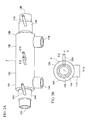
- Fig. 2A is an external perspective view of the reversing valve main body 2 shown in Fig. 1
- Fig. 2B is a side view of the reversing valve main body 2 shown in Fig. 2A as viewed from the left.
- Fig. 3A is a partially cutaway sectional view of the flow regulating valve 3 shown in Fig. 1
- Fig. 3B is a sectional view taken along and as viewed in the direction of arrows Y-Y in Fig. 3A .
- reversing valve main body 2 portion of Fig. 1 is a sectional view taken along and as viewed in the direction of arrows X-X in Fig. 2B
- the flow regulating valve 3 portion of Fig. 1 is identical to Fig. 3B .
- the flow reversing valve 1 of the present embodiment has been developed for use as a three-way reversing valve in a heat pump device such as that shown in Figs. 9A and 9B mentioned above (details will be discussed later with reference to Figs. 4A and 4B ). It basically comprises: the reversing valve main body 2 comprising a first main valve part 10A and a second main valve part 10B which are arranged symmetrically on the left and right and configured as two-way valves; and the flow regulating valve 3 of an electric motor type (rotary type), which serves as a pilot valve (back pressure regulating means) with respect to the first main valve part 10A and the second main valve part 10B.
- the reversing valve main body 2 comprising a first main valve part 10A and a second main valve part 10B which are arranged symmetrically on the left and right and configured as two-way valves
- the flow regulating valve 3 of an electric motor type (rotary type) which serves as a pilot valve (back pressure regulating means
- the first main valve part 10A and the second main valve part 10B of the reversing valve main body 2 respectively comprise cylindrical main valve cases 13A and 13B each having a base.
- the main valve cases 13A and 13B are integrated back to back so as to share a base part 13c, and their tip parts 13a and 13b are open.
- Main valve seats 14A and 14B that respectively have main valve openings 14a and 14b are respectively provided at the tip parts 13a and 13b of the main valve cases 13A and 13B.
- Main valve members 15A and 15B that respectively have poppet parts 15a and 15b for opening/closing the respective main valve openings 14a and 14b are fitted within the respective main valve cases 13A and 13B in a freely slidable manner.
- Seal materials 15c and 15c for suppressing or sealing leaks are provided on the outer circumferences of the main valve members 15A and 15B. Further, a protruding stopper 15d for restricting the fully open position is provided at the rear end face of each of the main valve members 15A and 15B.
- Main valve chambers 16A and 16B are respectively formed between the main valve seats 14A and 14B (main valve openings 14a and 14b) and the main valve members 15A and 15B of the respective main valve cases 13A and 13B.
- Outlets 12A and 12B through which the fluid is led out are respectively formed downstream of the main valve openings 14a and 14b.
- back pressure chambers 17A and 17B are respectively formed between the base part 13c and the main valve members 15A and 15B of the respective main valve cases 13A and 13B.
- Pressure equalizing holes 18A and 18B that respectively communicate the main valve chambers 16A and 16B with the back pressure chambers 17A and 17B are formed in the respective main valve members 15A and 15B.
- valve closing springs 19A and 19B comprising compression coil springs that constantly bias the respective main valve members 15A and 15B in the valve closing direction are provided, in a compressed manner, between the respective main valve members 15A and 15B and the base part 13c within the back pressure chambers 17A and 17B.
- the reversing valve main body 2 thus constructed is capable of assuming a first circulatory state, where the first main valve part 10A is placed in a fully open state by moving the main valve member 15A away from the main valve seat 14A and the second main valve part 10B is placed in a fully closed state by seating the main valve member 15B in the main valve seat 14B, and a second circulatory state, where the first main valve part 10A is placed in a fully closed state by seating the main valve member 15A in the main valve seat 14A and the second main valve part 10B is placed in a fully open state by moving the main valve member 15B away from the main valve seat 14B.
- the inlet 11A and the outlet 12A of the first main valve part 10A are in communication with each other, while the path between the inlet 11B and the outlet 12B of the second main valve part 10B is blocked.
- the second circulatory state the path between the inlet 11A and the outlet 12A of the first main valve part 10A is blocked, while the inlet 11B and the outlet 12B of the second main valve part 10B are in communication with each other.
- the flow reversing valve 1 of the present embodiment comprises a back pressure regulating means that regulates the pressure of each of the back pressure chambers 17A and 17B of the respective first main valve part 10A and the second main valve part 10B.
- the back pressure regulating means comprises: escape ports 21A and 21B respectively provided in the back pressure chambers 17A and 17B; discharge ports 22A and 22B respectively provided in the main valve seats 14A and 14B (downstream of the main valve openings 14a and 14b); and the flow regulating valve 3.
- the flow regulating valve 3 comprises: a tubular valve housing 30 with a base and having a valve seat part 31; a can 36 whose lower end part is sealingly joined with the valve housing 30; a stepping motor 35 comprising a rotor 37 disposed on the inner circumferential side of the can 36 and a stator 38 that is externally fitted and fixed on the outer circumference of the can 36; and a rotary valve member 32 of an inverted T-shaped cross-section, which is rotated by this stepping motor 35.
- a vertical part 32a thereof is rotatably supported by a guide member 33 that is affixed to the upper portion of the valve housing 30, and the lower end face thereof is pressed strongly against the valve seat part 31 by way of the biasing force of a compression coil spring 34 disposed between a lower part 32b of the rotary valve member 32 and the guide member 33.
- valve seat part 31 There are provided in the valve seat part 31 and such that they lie on the circumference of the same circle: a first port 41 and a second port 42 to which the escape port 21A and the discharge port 22A provided in the first main valve part 10A are to be connected, respectively; and a third port 43 and a fourth port 44 to which the escape port 21 B and the discharge port 22B provided in the second main valve part 10B are to be connected, respectively.
- the positional relationship among the ports may be such that the second port 42 is provided at an anti-clockwise angular interval of approximately 60 degrees relative to the first port 41, the third port 43 is provided at an anti-clockwise angular interval of approximately 140 degrees relative to the second port 42, the fourth port 44 is provided at an anti-clockwise angular interval of approximately 60 degrees relative to the third port 43, and the angular interval between the fourth port 44 and the first port 41 is approximately 100 degrees.
- a communicating channel 40 for selectively placing the first port 41 and the second port 42 or the third port 43 and the fourth port 44 in communication with each other, the communicating channel 40 having an open lower face and being of a fan-shape with rounded corners in planar view (the central angle being approximately 90 degrees).
- the flow regulating valve 3 thus structured is so arranged as to rotate the rotary valve member 32 relatively slowly by regulating the excitation speed of the stator 38, for example. It is noted that for such purposes as reducing the rotation speed of the rotary valve member 32 or obtaining a high torque, it is possible to employ, besides the above, such methods as installing a gear reduction mechanism between the rotor 37 and the rotary valve member 32, and so forth.
- the forces acting on the main valve members 15A and 15B in the valve closing direction i.e., the pressures of the back pressure chambers 17A and 17B + the biasing forces of the valve closing springs 19A and 19B
- the forces acting in the valve opening direction i.e., pressures Pa of the main valve chambers 16A and 16B.
- the second main valve part 10B transitions from a fully closed state to a half open state and then to a fully open state as in the first main valve part 10A shown in Figs. 5A to 5C mentioned above.
- the flow reversing valve 1 enters the second circulatory state. This period between Figs. 7A and 7D corresponds to the period between times t11 and t14 in Fig. 8 .
- the second main valve part 10B transitions from a fully open state to a half open state and then to a fully closed state as in the first main valve part 10A shown in Figs. 6A to 6D mentioned above.
- This operation of the second main valve part 10B is similar to that of the first main valve part 10A, and its description will therefore be omitted.
- the flow reversing valve 1 of the present embodiment by regulating the excitation speed of the stator 38 of the flow regulating valve 3 (or by installing a gear reduction mechanism between the rotor 37 and the rotary valve member 32, and so forth), the rotary valve member 32 is rotated relatively slowly.
- the flow reversing valve 1 is thus so arranged as to be placed in the first circulatory state by gradually reducing the pressure of the back pressure chamber 17A of the first main valve part 10A, and to be placed in the second circulatory state by gradually reducing the pressure of the back pressure chamber 17B of the second main valve part 10B.
- the flow regulating valve 3 is so arranged as to serve as a pilot valve for both main valve parts 10A and 10B, flow reversal can be performed with a smaller driving force as compared to conventional valves of an electromagnetic type. Accordingly, it is possible to reduce energy consumption, such as power consumption, etc., from this point as well.
- the flow reversing operation speed and the main valve opening/closing operation speed may be adjusted in accordance with the specifications of the heat pump system, etc., in which this flow reversing valve is to be employed.
- a single rotary four-port flow regulating valve 3 is used as a back pressure regulating means.
- a four-port flow regulating valve of a kind other than a rotary valve may be used, or two two-port flow regulating vales, etc., may be used in its place.
- two two-way valves (ON/OFF valves), etc. may be used in place of the flow regulating valve so as to only perform the flow reversing operation, or the main valve opening/closing operation, gently.
- the inlets 11A and 11B may be combined into one inlet using a tee fitting, etc., or the outlets 12A and 12B may be combined into one outlet using a tee fitting, etc., for example.
- a first flow reversing valve 1A of the same structure as the embodiment above is disposed between the discharge side of the compressor 210 and the condenser 220, and a second flow reversing valve 1B of the same structure as the embodiment above is disposed between the evaporator 230 and the suction side of the compressor 210.
- the inlet 11A of the first main valve part 10A and the inlet 11 B of the second main valve part 10B are each connected to the discharge side of the compressor 210 via a tee fitting 310, etc.
- the outlet 12A of the first main valve part 10A is connected to the condenser 220
- the outlet 12B of the second main valve part 10B is connected to the evaporator 230.
- the inlet 11A of the first main valve part 10A is connected to the evaporator 230
- the inlet 11B of the second main valve part 10B is connected to the condenser 220
- the outlet 12A of the first main valve part 10A and the outlet 12B of the second main valve part 10B are each connected to the suction side of the compressor 210 via a tee fitting 320, etc.
- the first flow reversing valve 1A assumes the first circulatory state
- the second flow reversing valve 1B also assumes the first circulatory state.
- the refrigerant discharged from the compressor 210 thus flows as follows: the inlet 11A of the first flow reversing valve 1A ⁇ the outlet 12A of the first flow reversing valve 1A ⁇ the condenser 220 ⁇ the expansion valve 250 ⁇ the evaporator 230 ⁇ the inlet 11A of the second flow reversing valve 1B ⁇ the outlet 12A of the second flow reversing valve 1B ⁇ the suction side of the compressor 210.
- the first flow reversing valve 1A assumes the second circulatory state
- the second flow reversing valve 1B also assumes the second circulatory state.
- the refrigerant discharged from the compressor 210 thus flows as follows: the inlet 11B of the first flow reversing valve 1A ⁇ the outlet 12B of the first flow reversing valve 1A ⁇ the evaporator 230 ⁇ the expansion valve 250 ⁇ the condenser 220 ⁇ the inlet 11B of the second flow reversing valve 1B ⁇ the outlet 12B of the second flow reversing valve 1B ⁇ the suction side of the compressor 210.
Landscapes
- Engineering & Computer Science (AREA)
- General Engineering & Computer Science (AREA)
- Mechanical Engineering (AREA)
- Multiple-Way Valves (AREA)
- Compression-Type Refrigeration Machines With Reversible Cycles (AREA)
- Fluid-Driven Valves (AREA)
Abstract
Description
- The present invention relates to a flow reversing valve, such as a three-way reversing valve, etc., that changes the flow direction of a fluid, and to a heat pump device using same.
- Heat pump devices (air conditioners, etc.) generally comprise a four-way reversing valve as a flow path (flow direction) reversing means in addition to a compressor, a vapor-liquid separator, a condenser (outdoor heat exchanger), an evaporator (indoor heat exchanger), an expansion valve, etc. (see
JP Patent Publication (Kokai) No. 2001-295951 A - However, with such heat pump devices employing a four-way reversing valve, since a high-temperature and high-pressure refrigerant and a low-temperature and low-pressure refrigerant flow in close proximity to each other within the four-way reversing valve, there is a problem in that the amount of heat transferred (heat transfer amount) from the high-temperature and high-pressure refrigerant to the low-temperature and low-pressure refrigerant becomes greater, thereby causing non-negligible heat loss and a drop in thermal efficiency.
- As such, the present inventors have contemplated having the flow reversing function of the four-way reversing valve provided by way of two three-way reversing valves instead. A schematic cycle example of such a heat pump device employing two three-way reversing valves is shown in
Figs. 9A and 9B . Theheat pump device 200 in the illustrated example comprises acompressor 210, a vapor-liquid separator (not shown), a condenser (outdoor heat exchanger) 220, an evaporator (indoor heat exchanger) 230, anexpansion valve 250, etc. Further, a first three-way reversing valve 100A is disposed between the discharge side of thecompressor 210 and thecondenser 220, and a second three-way reversing valve 100B is disposed between theevaporator 230 and the suction side of thecompressor 210. - The first three-
way reversing valve 100A comprises one inlet 11 and twooutlets outlet 12A are connected while the inlet 11 and theoutlet 12B are disconnected, and a second A circulatory state in which the inlet 11 and theoutlet 12A are disconnected while the inlet 11 and theoutlet 12B are connected. - The second three-
way reversing valve 100B comprises twoinlets outlet 12, and is so arranged as to be capable of assuming a first B circulatory state, in which theinlet 11A and theoutlet 12 are connected while theinlet 11B and theoutlet 12 are disconnected, and a second B circulatory state in which theinlet 11A and theoutlet 12 are disconnected while theinlet 11B and theoutlet 12 are connected. - With this
heat pump device 200, during cooling operation, as shown inFig. 9A , the first three-way reversing valve 100A assumes the first A circulatory state, and the second three-way reversing valve 100B assumes the first B circulatory state. Thus, the refrigerant discharged from thecompressor 210 flows as follows: the inlet 11 of the first three-way reversing valve 100A → theoutlet 12A of the first three-way reversing valve 100A →thecondenser 220 → theexpansion valve 250 → theevaporator 230 → theinlet 11A of the second three-way reversing valve 100B → theoutlet 12 of the second three-way reversing valve 100B → the suction side of thecompressor 210. - In contrast, during heating operation, as shown in
Fig. 9B , the first three-way reversing valve 100A assumes the second A circulatory state, and the second three-way reversing valve 100B assumes the second B circulatory state. Thus, the refrigerant discharged from thecompressor 210 flows as follows: the inlet 11 of the first three-way reversing valve 100A →theoutlet 12B of the first three-way reversing valve 100A → theevaporator 230 → theexpansion valve 250 → thecondenser 220 → theinlet 11B of the second three-way reversing valve 100B → theoutlet 12 of the second three-way reversing valve 100B → the suction side of thecompressor 210. - However, the flow reversing valves, such as conventional three-way reversing valves, etc., employed in the above-mentioned heat pump device, etc., are ordinarily of an electromagnetic type (i.e., a type in which a plunger valve member is attracted by a solenoid). Thus, the reversing (opening/closing) operation is extremely fast, lasting only a few hundred milliseconds, and there is a possibility that, due to the speed of the reversing operation thereof, flood backs (a phenomenon where the refrigerant is returned to the compressor, etc., while still partially in liquid form), impact sounds, etc., might occur, causing system failures in extreme cases.
- In addition, with electromagnetic valves, since it is necessary to continue applying a current even after the flow has been reversed, there are such problems as greater power consumption, etc.
- The present invention is made in view of the circumstances above, and an object thereof is to provide a flow reversing valve, such as a three-way reversing valve, etc., that is capable of gently performing a reversing operation, of effectively suppressing occurrences of flood backs, impact sounds, etc., and of reducing power consumption relative to electromagnetic valves, as well as to provide a heat pump device using same.
- In order to achieve the object above, one flow reversing valve according to the present invention basically comprises: a reversing valve main body comprising a first main valve part and a second main valve part, each of which is configured as a two-way valve, the reversing valve main body being so arranged as to be capable of assuming a first circulatory state, where the first main valve part is in a fully open state and the second main valve part is in a fully closed state, and a second circulatory state, where the first main valve part is in a fully closed state and the second main valve part is in a fully open state; and a pressure regulating means that serves as a pilot valve for the first main valve part and the second main valve part.
- Another flow reversing valve according to the present invention comprises: a reversing valve main body comprising a first main valve part and a second main valve part, each being formed with an inlet, an outlet, a valve chamber, and a back pressure chamber, the reversing valve main body being so arranged as to be capable of assuming a first circulatory state, where the first main valve part is in a fully open state and the second main valve part is in a fully closed state, and a second circulatory state, where the first main valve part is in a fully closed state and the second main valve part is in a fully open state; and back pressure regulating means configured to regulate the respective pressures of the back pressure chambers of the first main valve part and the second main valve part, wherein the back pressure regulating means is so arranged as to cause the reversing valve main body to assume the first circulatory state by gradually reducing the pressure of the back pressure chamber of the first main valve part, and to assume the second circulatory state by gradually reducing the pressure of the back pressure chamber of the second main valve part.
- Preferably, the first main valve part and the second main valve part each comprise a tubular main valve case with a base. The main valve case is provided with a main valve seat having a main valve opening, and a main valve member that opens/closes the main valve opening is fitted in the main valve case in a freely slidable manner. A main valve chamber is formed between the main valve seat and the main valve member, an inlet that opens into the main valve chamber is formed, and an outlet is formed downstream of the main valve opening. A back pressure chamber is formed between a base part of the main valve case and the main valve member, and a pressure equalizing hole that places the main valve chamber and the back pressure chamber in communication with each other is provided in the main valve member.
- In this case, a valve closing spring that constantly biases the main valve member in the valve closing direction is preferably disposed in the respective back pressure chambers of the first main valve part and the second main valve part.
- The back pressure regulating means preferably comprises a single flow regulating valve or two flow regulating valves that is/are capable of regulating the respective amounts of fluid to be released to the outlet from the back pressure chambers of the first main valve part and the second main valve part.
- On the other hand, a heat pump device according to the present invention comprises: a compressor; a condenser; an evaporator; and an expansion valve, wherein a first flow reversing valve of the structure above is disposed between the discharge side of the compressor and the condenser, and a second flow reversing valve of the structure above is disposed between the evaporator and the suction side of the compressor.
- In this case, in a more preferable embodiment, with respect to the first flow reversing valve, the inlet of the first main valve part and the inlet of the second main valve part are both connected to the discharge side of the compressor, and one of the outlet of the first main valve part and the outlet of the second main valve part is connected to the condenser while the other is connected to the evaporator. With respect to the second flow reversing valve, one of the inlet of the first main valve part and the inlet of the second main valve part is connected to the condenser while the other is connected to the evaporator, and the outlet of the first main valve part and the outlet of the second main valve part are both connected to the suction side of the compressor.
- In a preferred embodiment of a flow reversing valve according to the present invention, the first circulatory state is assumed by reducing the pressure of the back pressure chamber of the first main valve part, and the second circulatory state is assumed by reducing the pressure of the back pressure chamber of the second main valve part. Thus, with respect to the first main valve part and the second main valve part, the transition from a fully closed state to a fully open state and the transition from a fully open state to a fully closed state (main valve opening/closing operation), as well as the switch from the first circulatory state to the second circulatory state and the switch from the second circulatory state to the first circulatory state (flow reversing operation) can all be performed gently. As a result, it is possible to effectively suppress occurrences of flood backs, impact sounds, etc., and to thereby prevent system failures, etc., with respect to heat pump devices, etc., that employ the flow reversing valve above.
- In addition, since there is no need to apply, after flow reversal, a current to the back pressure regulating means comprising the flow regulating valve(s), etc., it is possible to reduce power consumption relative to those of an electromagnetic type.
- Further, since the back pressure regulating means comprising the flow regulating valve(s), etc., is so arranged as to serve as a pilot valve with respect to both main valve parts, flow reversal can be carried out with a smaller driving force as compared to those of the conventional electromagnetic type, it is possible to reduce energy consumption, such as power consumption, etc., from this point as well.
-
-
Fig. 1 is a schematic configuration diagram showing one embodiment of a flow reversing valve according to the present invention. -
Fig. 2A is an external perspective view of the reversing valve main body shown inFig. 1 , andFig. 2B is a side view of the reversing valve main body shown inFig. 2A as seen from the left. -
Fig. 3A is a partially cutaway sectional view of the flow regulating valve shown inFig. 1 , andFig. 3B is a sectional view taken along and as viewed in the direction of arrows Y-Y inFig. 3A . -
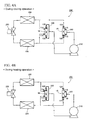
Figs. 4A and 4B are diagrams showing schematic cycle examples of a heat pump device employing the flow reversing valve shown inFig. 1 . -
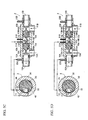
Figs. 5A through 5D are diagrams illustrating the operation of the flow reversing valve shown inFig. 1 . -
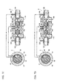
Figs. 6A through 6D are diagrams illustrating the operation of the flow reversing valve shown inFig. 1 . -
Figs. 7A through 7D are diagrams illustrating the operation of the flow reversing valve shown inFig. 1 . -
Figs. 8A through 8C are timing diagrams illustrating the operation of the flow reversing valve shown inFig. 1 . -
Figs. 9A and 9B are diagrams showing schematic cycle examples of a heat pump device employing two three-way reversing valves. -
- 1 (1A, 1B)
- Flow reversing valve (three-way reversing valve)
- 2
- Reversing valve main body
- 3
- Flow regulating valve
- 10A, 10B
- Main valve part
- 11A, 11B
- Inlet
- 12A, 12B
- Outlet
- 13A, 13B
- Main valve case
- 14A, 14B
- Main valve seat
- 15A, 15B
- Main valve member
- 16A, 16B
- Main valve chamber
- 17A, 17B
- Back pressure chamber
- 18A, 18B
- Pressure equalizing hole
- 19A, 19B
- Valve closing spring
- 21A, 21B
- Escape port
- 22A, 22B
- Discharge port
- 30
- Valve housing
- 32
- Rotary valve member
- 35
- Stepping motor
- 37
- Rotor
- 38
- Stator
- 40
- Communicating channel
- 41
- First port
- 42
- Second port
- 43
- Third port
- 44
- Fourth port
- 200, 200'
- Heat pump device
- 210
- Compressor
- 220
- Condenser
- 230
- Evaporator
- 250
- Expansion valve
- Embodiments of a flow reversing valve of the present invention are described below with reference to the drawings.
-
Fig. 1 is a schematic configuration diagram showing one embodiment of a flow reversing valve according to the present invention. Theflow reversing valve 1 shown in the diagram comprises a reversing valvemain body 2 and aflow regulating valve 3.Fig. 2A is an external perspective view of the reversing valvemain body 2 shown inFig. 1 , andFig. 2B is a side view of the reversing valvemain body 2 shown inFig. 2A as viewed from the left.Fig. 3A is a partially cutaway sectional view of theflow regulating valve 3 shown inFig. 1 , andFig. 3B is a sectional view taken along and as viewed in the direction of arrows Y-Y inFig. 3A . It is noted that the reversing valvemain body 2 portion ofFig. 1 is a sectional view taken along and as viewed in the direction of arrows X-X inFig. 2B , and theflow regulating valve 3 portion ofFig. 1 is identical toFig. 3B . - The
flow reversing valve 1 of the present embodiment has been developed for use as a three-way reversing valve in a heat pump device such as that shown inFigs. 9A and 9B mentioned above (details will be discussed later with reference toFigs. 4A and 4B ). It basically comprises: the reversing valvemain body 2 comprising a firstmain valve part 10A and a secondmain valve part 10B which are arranged symmetrically on the left and right and configured as two-way valves; and theflow regulating valve 3 of an electric motor type (rotary type), which serves as a pilot valve (back pressure regulating means) with respect to the firstmain valve part 10A and the secondmain valve part 10B. - The first
main valve part 10A and the secondmain valve part 10B of the reversing valvemain body 2 respectively comprise cylindricalmain valve cases main valve cases base part 13c, and theirtip parts Main valve seats main valve openings tip parts main valve cases Main valve members poppet parts main valve openings main valve cases Seal materials main valve members stopper 15d for restricting the fully open position is provided at the rear end face of each of themain valve members -
Main valve chambers main valve seats main valve openings main valve members main valve cases Inlets main valve chambers Outlets main valve openings - Further,
back pressure chambers base part 13c and themain valve members main valve cases holes main valve chambers back pressure chambers main valve members main valve members main valve members base part 13c within theback pressure chambers - The reversing valve
main body 2 thus constructed is capable of assuming a first circulatory state, where the firstmain valve part 10A is placed in a fully open state by moving themain valve member 15A away from themain valve seat 14A and the secondmain valve part 10B is placed in a fully closed state by seating themain valve member 15B in themain valve seat 14B, and a second circulatory state, where the firstmain valve part 10A is placed in a fully closed state by seating themain valve member 15A in themain valve seat 14A and the secondmain valve part 10B is placed in a fully open state by moving themain valve member 15B away from themain valve seat 14B. - In the first circulatory state, the
inlet 11A and theoutlet 12A of the firstmain valve part 10A are in communication with each other, while the path between theinlet 11B and theoutlet 12B of the secondmain valve part 10B is blocked. In the second circulatory state, the path between theinlet 11A and theoutlet 12A of the firstmain valve part 10A is blocked, while theinlet 11B and theoutlet 12B of the secondmain valve part 10B are in communication with each other. - On the other hand, the
flow reversing valve 1 of the present embodiment comprises a back pressure regulating means that regulates the pressure of each of theback pressure chambers main valve part 10A and the secondmain valve part 10B. - The back pressure regulating means comprises: escape
ports back pressure chambers discharge ports main valve seats main valve openings flow regulating valve 3. - As shown in
Fig. 3A , theflow regulating valve 3 comprises: atubular valve housing 30 with a base and having avalve seat part 31; acan 36 whose lower end part is sealingly joined with thevalve housing 30; a steppingmotor 35 comprising arotor 37 disposed on the inner circumferential side of thecan 36 and astator 38 that is externally fitted and fixed on the outer circumference of thecan 36; and arotary valve member 32 of an inverted T-shaped cross-section, which is rotated by this steppingmotor 35. - With respect to the
rotary valve member 32, avertical part 32a thereof is rotatably supported by aguide member 33 that is affixed to the upper portion of thevalve housing 30, and the lower end face thereof is pressed strongly against thevalve seat part 31 by way of the biasing force of acompression coil spring 34 disposed between alower part 32b of therotary valve member 32 and theguide member 33. - There are provided in the
valve seat part 31 and such that they lie on the circumference of the same circle: afirst port 41 and asecond port 42 to which theescape port 21A and thedischarge port 22A provided in the firstmain valve part 10A are to be connected, respectively; and athird port 43 and afourth port 44 to which theescape port 21 B and thedischarge port 22B provided in the secondmain valve part 10B are to be connected, respectively. By way of example, the positional relationship among the ports may be such that thesecond port 42 is provided at an anti-clockwise angular interval of approximately 60 degrees relative to thefirst port 41, thethird port 43 is provided at an anti-clockwise angular interval of approximately 140 degrees relative to thesecond port 42, thefourth port 44 is provided at an anti-clockwise angular interval of approximately 60 degrees relative to thethird port 43, and the angular interval between thefourth port 44 and thefirst port 41 is approximately 100 degrees. - Further, in the lower half part of the
lower part 32b of thevalve member 32 is provided a communicatingchannel 40 for selectively placing thefirst port 41 and thesecond port 42 or thethird port 43 and thefourth port 44 in communication with each other, the communicatingchannel 40 having an open lower face and being of a fan-shape with rounded corners in planar view (the central angle being approximately 90 degrees). - The
flow regulating valve 3 thus structured is so arranged as to rotate therotary valve member 32 relatively slowly by regulating the excitation speed of thestator 38, for example. It is noted that for such purposes as reducing the rotation speed of therotary valve member 32 or obtaining a high torque, it is possible to employ, besides the above, such methods as installing a gear reduction mechanism between therotor 37 and therotary valve member 32, and so forth. - Next, the operation of the
flow reversing valve 1 thus structured will be described with reference toFigs. 5A-5D throughFigs. 7A-7D and to the timing diagrams inFig. 8 . - As shown in
Fig. 5A , in a state where therotary valve member 32 only opens thefirst port 41, that is, in a state where none of thefirst port 41 and thesecond port 42, as well as thethird port 43 and thefourth port 44, are in communication with one another, the refrigerant in the respectiveback pressure chambers main valve part 10A and the secondmain valve part 10B is not discharged. Thus, for bothmain valve parts main valve members back pressure chambers main valve chambers pressure equalizing holes back pressure chambers main valve parts valve chambers back pressure chambers valve chambers main valve members main valve seats main valve part 10A and the secondmain valve part 10B are placed in a fully closed state. This state corresponds to the state before time t1 inFig. 8 , that is, a state where the effective opening areas of theescape ports back pressure chambers valve chambers main valve parts - As the
rotary valve member 32 is rotated anti-clockwise from the state shown inFig. 5A and thesecond port 42 is slightly opened as shown inFig. 5B , thefirst port 41 and thesecond port 42 are placed in communication with each other via the communicatingchannel 40. At this point, the opening area of thesecond port 42 becomes the effective opening area of theescape port 21A. Thus, the refrigerant within theback pressure chamber 17A flows as follows and the pressure of theback pressure chamber 17A drops slightly: escapeport 21A →first port 41 → communicatingchannel 40 →second port 42 →discharge port 22A →outlet 12A. However, since, at this point, the force acting in the valve closing direction is still greater than the force acting in the valve opening direction, the firstmain valve part 10A remains in a fully closed state. This period betweenFigs. 5A and 5B corresponds to the period between times t1 and t2 inFig. 8 . - As the
rotary valve member 32 is further rotated anti-clockwise from the state shown inFig. 5B and thesecond port 42 is opened by about 2/3 as shown inFig. 5C , the pressure of theback pressure chamber 17A drops further. As a result, themain valve member 15A moves to the right and is slightly separated from themain valve seat 14A, the firstmain valve part 10A is placed in a half open state, and the refrigerant flows out from theinlet 11A to theoutlet 12A while being throttled to some extent. This period betweenFigs. 5B and5C corresponds to the period between times t2 and t3 inFig. 8 . - As the
rotary valve member 32 is further rotated anti-clockwise from the state shown inFig. 5C and thesecond port 42 is fully opened as shown inFig. 5D , the pressure of theback pressure chamber 17A drops further. As a result, themain valve member 15A moves further to the right and is significantly separated from themain valve seat 14A, the protrudingstopper 15d protruding from the rear end face thereof abuts thebase part 13c, and the firstmain valve part 10A is placed in a fully open state. Thus, theflow reversing valve 1 is placed in the first circulatory state, and the refrigerant flows from theinlet 11A to theoutlet 12A with virtually no throttling. This period betweenFigs. 5C and 5D corresponds to the period between times t3 and t4 inFig. 8 . - Here, at a point when the first circulatory state, in which the first
main valve part 10A is in a fully open state and the secondmain valve part 10B is in a fully closed state, is entered as shown inFig. 5D , if the application of a current to thestator 38 of themotor 35 is stopped, the rotation of therotary valve member 32 stops, therotary valve member 32 keeps the position shown inFig. 5D (i.e., the fully open position for theports 41 and 42), and theflow reversing valve 1 maintains the first circulatory state. This period of the first circulatory state corresponds to the period between times t4 and t5 inFig. 8 . - Next, as the
rotary valve member 32 is further rotated anti-clockwise from the state shown inFig. 5D and thefirst port 41 is slightly closed as shown inFig. 6A , the amount of refrigerant that is released from theback pressure chamber 17A decreases. As a result, the pressure of theback pressure chamber 17A increases to some extent due to the refrigerant introduced from thepressure equalizing hole 18A, themain valve member 15A moves slightly to the left, and the firstmain valve part 10A is placed in a half open state. This period betweenFig. 5D andFig. 6A corresponds to the period between times t5 and t6 inFig. 8 . - As the
rotary valve member 32 is further rotated anti-clockwise from the state shown inFig. 6A and thefirst port 41 is closed by about 2/3 as shown inFig. 6B , the amount of refrigerant that is released from theback pressure chamber 17A decreases further. As a result, the pressure of theback pressure chamber 17A increases due to the refrigerant introduced from thepressure equalizing hole 18A, themain valve member 15A moves further to the left, themain valve member 15A is seated in themain valve seat 14A, and the firstmain valve part 10A is placed in a fully closed state. This period betweenFigs. 6A and 6B corresponds to the period between times t6 and t7 inFig. 8 . - As the
rotary valve member 32 is further rotated anti-clockwise from the state shown inFig. 6B and thefirst port 41 is fully closed as shown inFig. 6C , there is created a state in which, as in the state shown inFig. 5A , none of thefirst port 41 and thesecond port 42, as well as thethird port 43 and thefourth port 44, are in communication with one another, themain valve member 15A is pressed against themain valve seat 14A due to the biasing force of thevalve closing spring 19A, and the firstmain valve part 10A and the secondmain valve part 10B are both placed in a fully closed state. This period betweenFigs. 6B and6C corresponds to the period between times t7 and t8 inFig. 8 . - As the
rotary valve member 32 is further rotated anti-clockwise from the state shown inFig. 6C and all of theports Fig. 6D , the firstmain valve part 10A and the secondmain valve part 10B both maintain their fully closed states. - Here, at a point when both
main valve parts Fig. 6C or 6D , if the application of a current to thestator 38 of themotor 35 is stopped, the rotation of therotary valve member 32 stops, therotary valve member 32 keeps the position shown inFig. 6C or 6D , and theflow reversing valve 1 maintains a state in which bothmain valve parts Fig. 8 . - Next, as the
rotary valve member 32 is further rotated anti-clockwise from the state shown inFig. 6D , the secondmain valve part 10B, as shown inFigs. 7A, 7B and7C , transitions from a fully closed state to a half open state and then to a fully open state as in the firstmain valve part 10A shown inFigs. 5A to 5C mentioned above. As the secondmain valve part 10B is placed in a fully open state as shown inFig. 7D , theflow reversing valve 1 enters the second circulatory state. This period betweenFigs. 7A and7D corresponds to the period between times t11 and t14 inFig. 8 . - Further, as the
rotary valve member 32 is further rotated anti-clockwise from the state shown inFig. 7D , the secondmain valve part 10B transitions from a fully open state to a half open state and then to a fully closed state as in the firstmain valve part 10A shown inFigs. 6A to 6D mentioned above. This operation of the secondmain valve part 10B is similar to that of the firstmain valve part 10A, and its description will therefore be omitted. - Thus, with the
flow reversing valve 1 of the present embodiment, by regulating the excitation speed of thestator 38 of the flow regulating valve 3 (or by installing a gear reduction mechanism between therotor 37 and therotary valve member 32, and so forth), therotary valve member 32 is rotated relatively slowly. Theflow reversing valve 1 is thus so arranged as to be placed in the first circulatory state by gradually reducing the pressure of theback pressure chamber 17A of the firstmain valve part 10A, and to be placed in the second circulatory state by gradually reducing the pressure of theback pressure chamber 17B of the secondmain valve part 10B. As a result, it is possible to gently perform the transitions for the firstmain valve part 10A and the secondmain valve part 10B from a fully closed state to a fully open state and from a fully open state to a fully closed state (main valve opening/closing operation), as well as the switches from the first circulatory state to the second circulatory state and from the second circulatory state to the first circulatory state (flow reversing operation). Accordingly, it is possible to effectively suppress occurrences of flood backs, impact sounds, etc., and to thereby prevent system failures, etc. - In addition, since there is no need to apply a current to the
flow regulating valve 3 once therotary valve member 32 has been placed in a certain position, such as after flow reversal, etc., it is possible to reduce power consumption relative to valves of an electromagnetic type. - Further, since the
flow regulating valve 3 is so arranged as to serve as a pilot valve for bothmain valve parts - It is noted that the flow reversing operation speed and the main valve opening/closing operation speed may be adjusted in accordance with the specifications of the heat pump system, etc., in which this flow reversing valve is to be employed.
- In addition, in the embodiment above, a single rotary four-port
flow regulating valve 3 is used as a back pressure regulating means. However, a four-port flow regulating valve of a kind other than a rotary valve may be used, or two two-port flow regulating vales, etc., may be used in its place. Further, as a back pressure regulating means, two two-way valves (ON/OFF valves), etc., may be used in place of the flow regulating valve so as to only perform the flow reversing operation, or the main valve opening/closing operation, gently. - Further, with respect to the
flow revering valve 1 of the embodiment above, two inlets and two outlets are provided. However, if the presentflow reversing valve 1 is to be used as a three-way reversing valve, theinlets outlets - Next, an example will be described with reference to
Figs. 4A and 4B where theflow reversing valve 1 in the embodiment above is used as three-way reversing valves (100A and 100B) in theheat pump device 200 shown inFig. 9 previously discussed. - In the heat pump device 200' in the illustrated example, a first
flow reversing valve 1A of the same structure as the embodiment above is disposed between the discharge side of thecompressor 210 and thecondenser 220, and a secondflow reversing valve 1B of the same structure as the embodiment above is disposed between theevaporator 230 and the suction side of thecompressor 210. - More specifically, with respect to the first
flow reversing valve 1A, theinlet 11A of the firstmain valve part 10A and theinlet 11 B of the secondmain valve part 10B are each connected to the discharge side of thecompressor 210 via a tee fitting 310, etc., theoutlet 12A of the firstmain valve part 10A is connected to thecondenser 220, and theoutlet 12B of the secondmain valve part 10B is connected to theevaporator 230. - On the other hand, with respect to the second
flow reversing valve 1B, theinlet 11A of the firstmain valve part 10A is connected to theevaporator 230, theinlet 11B of the secondmain valve part 10B is connected to thecondenser 220, and theoutlet 12A of the firstmain valve part 10A and theoutlet 12B of the secondmain valve part 10B are each connected to the suction side of thecompressor 210 via a tee fitting 320, etc. - With the heat pump device 200' above, by controlling the flow regulating valve, during cooling operation, as shown in
Fig. 4A , the firstflow reversing valve 1A assumes the first circulatory state, and the secondflow reversing valve 1B also assumes the first circulatory state. The refrigerant discharged from thecompressor 210 thus flows as follows: theinlet 11A of the firstflow reversing valve 1A → theoutlet 12A of the firstflow reversing valve 1A → thecondenser 220 → theexpansion valve 250 → theevaporator 230 → theinlet 11A of the secondflow reversing valve 1B → theoutlet 12A of the secondflow reversing valve 1B → the suction side of thecompressor 210. - In contrast, during heating operation, as shown in
Fig. 4B , the firstflow reversing valve 1A assumes the second circulatory state, and the secondflow reversing valve 1B also assumes the second circulatory state. The refrigerant discharged from thecompressor 210 thus flows as follows: theinlet 11B of the firstflow reversing valve 1A → theoutlet 12B of the firstflow reversing valve 1A → theevaporator 230 → theexpansion valve 250 → thecondenser 220 → theinlet 11B of the secondflow reversing valve 1B → theoutlet 12B of the secondflow reversing valve 1B → the suction side of thecompressor 210. - It is thus possible to have the flow reversing function of a four-way reversing valve provided by using two of the
flow reversing valves 1 of the embodiment above in a heat pump device.
Claims (7)
- A flow reversing valve comprising:a reversing valve main body comprising a first main valve part and a second main valve part each configured as a two-way valve, the reversing valve main body being adapted to be capable of assuming a first circulatory state in which the first main valve part is in a fully open state and the second main valve part is in a fully closed state, and a second circulatory state in which the first main valve part is in a fully closed state and the second main valve part is in a fully open state; andpressure regulating means adapted to serve as a pilot valve for the first main valve part and the second main valve part.
- A flow reversing valve comprising:a reversing valve main body comprising a first main valve part and a second main valve part in each of which an inlet, an outlet, a valve chamber and a back pressure chamber are formed, the reversing valve main body being adapted to be capable of assuming a first circulatory state in which the first main valve part is in a fully open state and the second main valve part is in a fully closed state, and a second circulatory state in which the first main valve part is in a fully closed state and the second main valve part is in a fully open state; andback pressure regulating means adapted to regulate the pressure of each of the back pressure chambers of the first main valve part and the second main valve part, whereinthe back pressure regulating means is adapted to place the reversing valve main body in the first circulatory state by reducing the pressure of the back pressure chamber of the first main valve part, and in the second circulatory state by reducing the pressure of the back pressure chamber of the second main valve part.
- The flow reversing valve according to claim 1 or 2, wherein each of the first main valve part and the second main valve part comprises a tubular main valve case with a base,
in each of the main valve cases, a main valve seat having a main valve opening is provided and a main valve member adapted to open/close the main valve opening is fitted in a freely slidable manner,
between the main valve seat and the main valve member are formed a main valve chamber and the inlet, the inlet opening into the main valve chamber,
the outlet is formed downstream of the main valve opening,
the back pressure chamber is formed between the base of the main valve case and the main valve member, and
a pressure equalizing hole that communicates the main valve chamber with the back pressure chamber is provided in the main valve member. - The flow reversing valve according to claim 3, wherein a valve closing spring adapted to constantly bias the main valve member in a valve closing direction is disposed in each of the back pressure chambers of the first main valve part and the second main valve part.
- The flow reversing valve according to any one of claims 2 to 4, wherein the back pressure regulating means comprises one or two flow regulating valve(s) that is/are capable of regulating the amount of fluid that is released from the back pressure chamber to the outlet in each of the first main valve part and the second valve part.
- A heat pump device comprising a compressor, a condenser, an evaporator and an expansion valve, wherein
a first flow reversing valve according to any one of claims 1 to 5 is disposed between a discharge side of the compressor and the condenser, and
a second flow reversing valve according to any one of claims 1 to 5 is disposed between the evaporator and a suction side of the compressor. - The heat pump device according to claim 6, wherein
with respect to the first flow reversing valve, the inlet of the first main valve part and the inlet of the second main valve part are each connected to the discharge side of the compressor, and one of the outlet of the first main valve part and the outlet of the second main valve part is connected to the condenser while the other is connected to the evaporator, and
with respect to the second flow reversing valve, one of the inlet of the first main valve part and the inlet of the second main valve part is connected to the condenser while the other is connected to the evaporator, and the outlet of the first main valve part and the outlet of the second main valve part are each connected to the suction side of the compressor.
Applications Claiming Priority (1)
| Application Number | Priority Date | Filing Date | Title |
|---|---|---|---|
| JP2010068093A JP5645437B2 (en) | 2010-03-24 | 2010-03-24 | Channel switching valve, switching valve main body used for channel switching valve, and heat pump device using the same |
Publications (2)
| Publication Number | Publication Date |
|---|---|
| EP2375116A1 true EP2375116A1 (en) | 2011-10-12 |
| EP2375116B1 EP2375116B1 (en) | 2012-12-26 |
Family
ID=44070670
Family Applications (1)
| Application Number | Title | Priority Date | Filing Date |
|---|---|---|---|
| EP20110002293 Active EP2375116B1 (en) | 2010-03-24 | 2011-03-21 | Flow reversing valve and heat pump device using the same |
Country Status (3)
| Country | Link |
|---|---|
| US (1) | US9080688B2 (en) |
| EP (1) | EP2375116B1 (en) |
| JP (1) | JP5645437B2 (en) |
Cited By (2)
| Publication number | Priority date | Publication date | Assignee | Title |
|---|---|---|---|---|
| CN108006263A (en) * | 2017-12-01 | 2018-05-08 | 宁波文泽机电技术开发有限公司 | Open type guide type electromagnetic ball valve |
| CN110715081A (en) * | 2019-10-11 | 2020-01-21 | 杨叶莹 | A mechanical linkage check valve with adjustable check direction |
Families Citing this family (13)
| Publication number | Priority date | Publication date | Assignee | Title |
|---|---|---|---|---|
| EP2683995B1 (en) * | 2011-03-09 | 2015-04-22 | Danfoss A/S | An expansion valve for a vapour compression system with reversible fluid flow |
| NO336835B1 (en) * | 2012-03-21 | 2015-11-16 | Inflowcontrol As | An apparatus and method for fluid flow control |
| EP2808259B1 (en) * | 2013-05-31 | 2016-04-13 | Airbus Defence and Space SA | Dual pressure regulation system for aerial refueling operations |
| JP6456155B2 (en) * | 2015-01-19 | 2019-01-23 | 日本電産トーソク株式会社 | Spool switching valve device |
| JP6486736B2 (en) * | 2015-03-18 | 2019-03-20 | 日本電産トーソク株式会社 | Spool switching valve device |
| JP6672598B2 (en) * | 2015-03-24 | 2020-03-25 | 日本電産トーソク株式会社 | Spool switching valve device |
| CN109027330B (en) * | 2018-10-10 | 2024-03-15 | 上海高中压阀门股份有限公司 | Shut-off control valve and method of use |
| CN114526358A (en) * | 2020-11-23 | 2022-05-24 | 中核苏阀科技实业股份有限公司 | A new type of three-way automatic reversing bypass valve |
| US12031755B2 (en) | 2021-05-19 | 2024-07-09 | Copeland Lp | Refrigeration system having high-efficiency loop |
| EP4367423A1 (en) * | 2021-07-09 | 2024-05-15 | Danfoss A/S | Hydraulic valves |
| CN114877102B (en) * | 2022-05-20 | 2025-12-16 | 大连中和聚能自动控制系统有限公司 | High-flow valve body for pneumatic valve positioner |
| US12259163B2 (en) | 2022-06-01 | 2025-03-25 | Copeland Lp | Climate-control system with thermal storage |
| US12416308B2 (en) | 2022-12-28 | 2025-09-16 | Copeland Lp | Compressor with shutdown assembly |
Citations (4)
| Publication number | Priority date | Publication date | Assignee | Title |
|---|---|---|---|---|
| US2459148A (en) * | 1944-09-20 | 1949-01-18 | Niels A Christensen | Fluid control apparatus |
| GB1338727A (en) * | 1971-05-06 | 1973-11-28 | Cameron Iron Works Inc | Flow control systems |
| FR2615922A1 (en) * | 1987-05-29 | 1988-12-02 | Samiia | Assembly for remotely controlling the speed of a pneumatic motor |
| JP2001295951A (en) | 2000-02-10 | 2001-10-26 | Fuji Koki Corp | Four-way selector valve |
Family Cites Families (9)
| Publication number | Priority date | Publication date | Assignee | Title |
|---|---|---|---|---|
| JPH0357580U (en) * | 1989-10-09 | 1991-06-03 | ||
| JPH03282171A (en) * | 1990-03-29 | 1991-12-12 | Mitsubishi Electric Corp | Three-way valve for freezing cycle device |
| JPH03288071A (en) * | 1990-04-03 | 1991-12-18 | Mitsubishi Electric Corp | Three-way valve for refrigerating cycle device |
| JPH0477075U (en) * | 1990-11-16 | 1992-07-06 | ||
| JPH06235467A (en) * | 1993-02-05 | 1994-08-23 | Toto Ltd | Faucet device |
| EP1092928A4 (en) * | 1998-07-02 | 2005-01-05 | Saginomiyaseisakusho Kk | Flow path selector valve and method of selecting and driving the valve, compressor with flow path selector valve, and refrigerating cycle control device |
| US6869060B2 (en) * | 2003-04-04 | 2005-03-22 | Husco International, Inc. | Hydraulic poppet valve with force feedback |
| JP2006071148A (en) * | 2004-08-31 | 2006-03-16 | Fuji Koki Corp | Refrigerating cycle |
| US7621211B2 (en) * | 2007-05-31 | 2009-11-24 | Caterpillar Inc. | Force feedback poppet valve having an integrated pressure compensator |
-
2010
- 2010-03-24 JP JP2010068093A patent/JP5645437B2/en active Active
-
2011
- 2011-03-21 EP EP20110002293 patent/EP2375116B1/en active Active
- 2011-03-22 US US13/069,024 patent/US9080688B2/en active Active
Patent Citations (4)
| Publication number | Priority date | Publication date | Assignee | Title |
|---|---|---|---|---|
| US2459148A (en) * | 1944-09-20 | 1949-01-18 | Niels A Christensen | Fluid control apparatus |
| GB1338727A (en) * | 1971-05-06 | 1973-11-28 | Cameron Iron Works Inc | Flow control systems |
| FR2615922A1 (en) * | 1987-05-29 | 1988-12-02 | Samiia | Assembly for remotely controlling the speed of a pneumatic motor |
| JP2001295951A (en) | 2000-02-10 | 2001-10-26 | Fuji Koki Corp | Four-way selector valve |
Cited By (2)
| Publication number | Priority date | Publication date | Assignee | Title |
|---|---|---|---|---|
| CN108006263A (en) * | 2017-12-01 | 2018-05-08 | 宁波文泽机电技术开发有限公司 | Open type guide type electromagnetic ball valve |
| CN110715081A (en) * | 2019-10-11 | 2020-01-21 | 杨叶莹 | A mechanical linkage check valve with adjustable check direction |
Also Published As
| Publication number | Publication date |
|---|---|
| JP5645437B2 (en) | 2014-12-24 |
| US9080688B2 (en) | 2015-07-14 |
| EP2375116B1 (en) | 2012-12-26 |
| JP2011202687A (en) | 2011-10-13 |
| US20110232320A1 (en) | 2011-09-29 |
Similar Documents
| Publication | Publication Date | Title |
|---|---|---|
| EP2375116B1 (en) | Flow reversing valve and heat pump device using the same | |
| EP1975480B1 (en) | Motor-operated selector valve and refrigeration cycle device for refrigerators | |
| EP2378171B1 (en) | Channel switching valve and heat pump system using the same | |
| US11156296B2 (en) | Flow control valve | |
| EP2299154A1 (en) | Flow path selector valve | |
| JP2017025986A (en) | Linear motion type solenoid valve and four-way selector with linear motion type solenoid valve acting as pilot valve | |
| CN105823267B (en) | Heat pump system and adjusting method thereof | |
| JP6556000B2 (en) | Direct acting solenoid valve and four-way switching valve equipped with it as a pilot valve | |
| US7036744B2 (en) | Solenoid valve-equipped expansion valve | |
| JP2004138375A (en) | Differential valve | |
| WO2007070060A1 (en) | Heat pump with pulse width modulation control | |
| CN101762129B (en) | Flow passage switching valve and heat pump type air conditioner | |
| JP2966597B2 (en) | Two-way solenoid valve | |
| CN117146343A (en) | Heat pump system and control method | |
| JP2001343077A (en) | Control valve | |
| CN111981160B (en) | Multi-way valve and heat pump system | |
| CN112013563B (en) | Solenoid switching valve and heat pump system having the same | |
| CN113531152B (en) | Solenoid switching valve and refrigeration system having the same | |
| CN105485979B (en) | Heating power expansion valve and heat pump system with the heating power expansion valve | |
| JP2007071359A (en) | 3-way selector valve | |
| JP3256270B2 (en) | Reversible valve | |
| CN112815566B (en) | Solenoid switching valve and heat pump system having the same | |
| JP2002372160A (en) | Four way selector valve | |
| CN113531151B (en) | Solenoid switching valve and refrigeration system having the same | |
| CN113531150A (en) | Electromagnetic switching valve and refrigeration system having the same |
Legal Events
| Date | Code | Title | Description |
|---|---|---|---|
| PUAI | Public reference made under article 153(3) epc to a published international application that has entered the european phase |
Free format text: ORIGINAL CODE: 0009012 |
|
| AK | Designated contracting states |
Kind code of ref document: A1 Designated state(s): AL AT BE BG CH CY CZ DE DK EE ES FI FR GB GR HR HU IE IS IT LI LT LU LV MC MK MT NL NO PL PT RO RS SE SI SK SM TR |
|
| AX | Request for extension of the european patent |
Extension state: BA ME |
|
| 17P | Request for examination filed |
Effective date: 20120412 |
|
| RIC1 | Information provided on ipc code assigned before grant |
Ipc: F16K 31/124 20060101AFI20120507BHEP |
|
| GRAP | Despatch of communication of intention to grant a patent |
Free format text: ORIGINAL CODE: EPIDOSNIGR1 |
|
| GRAP | Despatch of communication of intention to grant a patent |
Free format text: ORIGINAL CODE: EPIDOSNIGR1 |
|
| GRAS | Grant fee paid |
Free format text: ORIGINAL CODE: EPIDOSNIGR3 |
|
| GRAA | (expected) grant |
Free format text: ORIGINAL CODE: 0009210 |
|
| AK | Designated contracting states |
Kind code of ref document: B1 Designated state(s): AL AT BE BG CH CY CZ DE DK EE ES FI FR GB GR HR HU IE IS IT LI LT LU LV MC MK MT NL NO PL PT RO RS SE SI SK SM TR |
|
| REG | Reference to a national code |
Ref country code: GB Ref legal event code: FG4D |
|
| REG | Reference to a national code |
Ref country code: CH Ref legal event code: EP |
|
| REG | Reference to a national code |
Ref country code: AT Ref legal event code: REF Ref document number: 590674 Country of ref document: AT Kind code of ref document: T Effective date: 20130115 |
|
| REG | Reference to a national code |
Ref country code: DE Ref legal event code: R096 Ref document number: 602011000632 Country of ref document: DE Effective date: 20130228 |
|
| PG25 | Lapsed in a contracting state [announced via postgrant information from national office to epo] |
Ref country code: FI Free format text: LAPSE BECAUSE OF FAILURE TO SUBMIT A TRANSLATION OF THE DESCRIPTION OR TO PAY THE FEE WITHIN THE PRESCRIBED TIME-LIMIT Effective date: 20121226 Ref country code: NO Free format text: LAPSE BECAUSE OF FAILURE TO SUBMIT A TRANSLATION OF THE DESCRIPTION OR TO PAY THE FEE WITHIN THE PRESCRIBED TIME-LIMIT Effective date: 20130326 Ref country code: SE Free format text: LAPSE BECAUSE OF FAILURE TO SUBMIT A TRANSLATION OF THE DESCRIPTION OR TO PAY THE FEE WITHIN THE PRESCRIBED TIME-LIMIT Effective date: 20121226 Ref country code: LT Free format text: LAPSE BECAUSE OF FAILURE TO SUBMIT A TRANSLATION OF THE DESCRIPTION OR TO PAY THE FEE WITHIN THE PRESCRIBED TIME-LIMIT Effective date: 20121226 Ref country code: HR Free format text: LAPSE BECAUSE OF FAILURE TO SUBMIT A TRANSLATION OF THE DESCRIPTION OR TO PAY THE FEE WITHIN THE PRESCRIBED TIME-LIMIT Effective date: 20121226 |
|
| REG | Reference to a national code |
Ref country code: AT Ref legal event code: MK05 Ref document number: 590674 Country of ref document: AT Kind code of ref document: T Effective date: 20121226 |
|
| REG | Reference to a national code |
Ref country code: LT Ref legal event code: MG4D |
|
| REG | Reference to a national code |
Ref country code: NL Ref legal event code: VDEP Effective date: 20121226 |
|
| PG25 | Lapsed in a contracting state [announced via postgrant information from national office to epo] |
Ref country code: GR Free format text: LAPSE BECAUSE OF FAILURE TO SUBMIT A TRANSLATION OF THE DESCRIPTION OR TO PAY THE FEE WITHIN THE PRESCRIBED TIME-LIMIT Effective date: 20130327 Ref country code: SI Free format text: LAPSE BECAUSE OF FAILURE TO SUBMIT A TRANSLATION OF THE DESCRIPTION OR TO PAY THE FEE WITHIN THE PRESCRIBED TIME-LIMIT Effective date: 20121226 Ref country code: LV Free format text: LAPSE BECAUSE OF FAILURE TO SUBMIT A TRANSLATION OF THE DESCRIPTION OR TO PAY THE FEE WITHIN THE PRESCRIBED TIME-LIMIT Effective date: 20121226 |
|
| PG25 | Lapsed in a contracting state [announced via postgrant information from national office to epo] |
Ref country code: BE Free format text: LAPSE BECAUSE OF FAILURE TO SUBMIT A TRANSLATION OF THE DESCRIPTION OR TO PAY THE FEE WITHIN THE PRESCRIBED TIME-LIMIT Effective date: 20121226 Ref country code: EE Free format text: LAPSE BECAUSE OF FAILURE TO SUBMIT A TRANSLATION OF THE DESCRIPTION OR TO PAY THE FEE WITHIN THE PRESCRIBED TIME-LIMIT Effective date: 20121226 Ref country code: CZ Free format text: LAPSE BECAUSE OF FAILURE TO SUBMIT A TRANSLATION OF THE DESCRIPTION OR TO PAY THE FEE WITHIN THE PRESCRIBED TIME-LIMIT Effective date: 20121226 Ref country code: BG Free format text: LAPSE BECAUSE OF FAILURE TO SUBMIT A TRANSLATION OF THE DESCRIPTION OR TO PAY THE FEE WITHIN THE PRESCRIBED TIME-LIMIT Effective date: 20130326 Ref country code: ES Free format text: LAPSE BECAUSE OF FAILURE TO SUBMIT A TRANSLATION OF THE DESCRIPTION OR TO PAY THE FEE WITHIN THE PRESCRIBED TIME-LIMIT Effective date: 20130406 Ref country code: RS Free format text: LAPSE BECAUSE OF FAILURE TO SUBMIT A TRANSLATION OF THE DESCRIPTION OR TO PAY THE FEE WITHIN THE PRESCRIBED TIME-LIMIT Effective date: 20121226 Ref country code: IS Free format text: LAPSE BECAUSE OF FAILURE TO SUBMIT A TRANSLATION OF THE DESCRIPTION OR TO PAY THE FEE WITHIN THE PRESCRIBED TIME-LIMIT Effective date: 20130426 Ref country code: AT Free format text: LAPSE BECAUSE OF FAILURE TO SUBMIT A TRANSLATION OF THE DESCRIPTION OR TO PAY THE FEE WITHIN THE PRESCRIBED TIME-LIMIT Effective date: 20121226 Ref country code: SK Free format text: LAPSE BECAUSE OF FAILURE TO SUBMIT A TRANSLATION OF THE DESCRIPTION OR TO PAY THE FEE WITHIN THE PRESCRIBED TIME-LIMIT Effective date: 20121226 |
|
| PG25 | Lapsed in a contracting state [announced via postgrant information from national office to epo] |
Ref country code: PT Free format text: LAPSE BECAUSE OF FAILURE TO SUBMIT A TRANSLATION OF THE DESCRIPTION OR TO PAY THE FEE WITHIN THE PRESCRIBED TIME-LIMIT Effective date: 20130426 Ref country code: RO Free format text: LAPSE BECAUSE OF FAILURE TO SUBMIT A TRANSLATION OF THE DESCRIPTION OR TO PAY THE FEE WITHIN THE PRESCRIBED TIME-LIMIT Effective date: 20121226 Ref country code: NL Free format text: LAPSE BECAUSE OF FAILURE TO SUBMIT A TRANSLATION OF THE DESCRIPTION OR TO PAY THE FEE WITHIN THE PRESCRIBED TIME-LIMIT Effective date: 20121226 Ref country code: PL Free format text: LAPSE BECAUSE OF FAILURE TO SUBMIT A TRANSLATION OF THE DESCRIPTION OR TO PAY THE FEE WITHIN THE PRESCRIBED TIME-LIMIT Effective date: 20121226 |
|
| PG25 | Lapsed in a contracting state [announced via postgrant information from national office to epo] |
Ref country code: DK Free format text: LAPSE BECAUSE OF FAILURE TO SUBMIT A TRANSLATION OF THE DESCRIPTION OR TO PAY THE FEE WITHIN THE PRESCRIBED TIME-LIMIT Effective date: 20121226 Ref country code: MC Free format text: LAPSE BECAUSE OF NON-PAYMENT OF DUE FEES Effective date: 20130331 |
|
| PLBE | No opposition filed within time limit |
Free format text: ORIGINAL CODE: 0009261 |
|
| STAA | Information on the status of an ep patent application or granted ep patent |
Free format text: STATUS: NO OPPOSITION FILED WITHIN TIME LIMIT |
|
| PG25 | Lapsed in a contracting state [announced via postgrant information from national office to epo] |
Ref country code: CY Free format text: LAPSE BECAUSE OF FAILURE TO SUBMIT A TRANSLATION OF THE DESCRIPTION OR TO PAY THE FEE WITHIN THE PRESCRIBED TIME-LIMIT Effective date: 20121226 |
|
| 26N | No opposition filed |
Effective date: 20130927 |
|
| REG | Reference to a national code |
Ref country code: IE Ref legal event code: MM4A |
|
| REG | Reference to a national code |
Ref country code: DE Ref legal event code: R097 Ref document number: 602011000632 Country of ref document: DE Effective date: 20130927 |
|
| PG25 | Lapsed in a contracting state [announced via postgrant information from national office to epo] |
Ref country code: IE Free format text: LAPSE BECAUSE OF NON-PAYMENT OF DUE FEES Effective date: 20130321 Ref country code: AL Free format text: LAPSE BECAUSE OF FAILURE TO SUBMIT A TRANSLATION OF THE DESCRIPTION OR TO PAY THE FEE WITHIN THE PRESCRIBED TIME-LIMIT Effective date: 20121226 |
|
| REG | Reference to a national code |
Ref country code: DE Ref legal event code: R084 Ref document number: 602011000632 Country of ref document: DE Effective date: 20140430 |
|
| PG25 | Lapsed in a contracting state [announced via postgrant information from national office to epo] |
Ref country code: MT Free format text: LAPSE BECAUSE OF FAILURE TO SUBMIT A TRANSLATION OF THE DESCRIPTION OR TO PAY THE FEE WITHIN THE PRESCRIBED TIME-LIMIT Effective date: 20121226 |
|
| REG | Reference to a national code |
Ref country code: CH Ref legal event code: PL |
|
| PG25 | Lapsed in a contracting state [announced via postgrant information from national office to epo] |
Ref country code: CH Free format text: LAPSE BECAUSE OF NON-PAYMENT OF DUE FEES Effective date: 20140331 Ref country code: LI Free format text: LAPSE BECAUSE OF NON-PAYMENT OF DUE FEES Effective date: 20140331 |
|
| PG25 | Lapsed in a contracting state [announced via postgrant information from national office to epo] |
Ref country code: SM Free format text: LAPSE BECAUSE OF FAILURE TO SUBMIT A TRANSLATION OF THE DESCRIPTION OR TO PAY THE FEE WITHIN THE PRESCRIBED TIME-LIMIT Effective date: 20121226 |
|
| PG25 | Lapsed in a contracting state [announced via postgrant information from national office to epo] |
Ref country code: TR Free format text: LAPSE BECAUSE OF FAILURE TO SUBMIT A TRANSLATION OF THE DESCRIPTION OR TO PAY THE FEE WITHIN THE PRESCRIBED TIME-LIMIT Effective date: 20121226 |
|
| PG25 | Lapsed in a contracting state [announced via postgrant information from national office to epo] |
Ref country code: HU Free format text: LAPSE BECAUSE OF FAILURE TO SUBMIT A TRANSLATION OF THE DESCRIPTION OR TO PAY THE FEE WITHIN THE PRESCRIBED TIME-LIMIT; INVALID AB INITIO Effective date: 20110321 Ref country code: MK Free format text: LAPSE BECAUSE OF FAILURE TO SUBMIT A TRANSLATION OF THE DESCRIPTION OR TO PAY THE FEE WITHIN THE PRESCRIBED TIME-LIMIT Effective date: 20121226 Ref country code: LU Free format text: LAPSE BECAUSE OF NON-PAYMENT OF DUE FEES Effective date: 20130321 |
|
| GBPC | Gb: european patent ceased through non-payment of renewal fee |
Effective date: 20150321 |
|
| PG25 | Lapsed in a contracting state [announced via postgrant information from national office to epo] |
Ref country code: IT Free format text: LAPSE BECAUSE OF NON-PAYMENT OF DUE FEES Effective date: 20150321 |
|
| PG25 | Lapsed in a contracting state [announced via postgrant information from national office to epo] |
Ref country code: GB Free format text: LAPSE BECAUSE OF NON-PAYMENT OF DUE FEES Effective date: 20150321 |
|
| REG | Reference to a national code |
Ref country code: FR Ref legal event code: PLFP Year of fee payment: 6 |
|
| REG | Reference to a national code |
Ref country code: FR Ref legal event code: PLFP Year of fee payment: 7 |
|
| REG | Reference to a national code |
Ref country code: FR Ref legal event code: PLFP Year of fee payment: 8 |
|
| PG25 | Lapsed in a contracting state [announced via postgrant information from national office to epo] |
Ref country code: IT Free format text: LAPSE BECAUSE OF NON-PAYMENT OF DUE FEES Effective date: 20150321 |
|
| PGRI | Patent reinstated in contracting state [announced from national office to epo] |
Ref country code: IT Effective date: 20180104 |
|
| PGFP | Annual fee paid to national office [announced via postgrant information from national office to epo] |
Ref country code: DE Payment date: 20250128 Year of fee payment: 15 |
|
| PGFP | Annual fee paid to national office [announced via postgrant information from national office to epo] |
Ref country code: FR Payment date: 20250210 Year of fee payment: 15 |
|
| PGFP | Annual fee paid to national office [announced via postgrant information from national office to epo] |
Ref country code: IT Payment date: 20250211 Year of fee payment: 15 |