EP2374739B1 - Restrictor clip - Google Patents
Restrictor clip Download PDFInfo
- Publication number
- EP2374739B1 EP2374739B1 EP11161437A EP11161437A EP2374739B1 EP 2374739 B1 EP2374739 B1 EP 2374739B1 EP 11161437 A EP11161437 A EP 11161437A EP 11161437 A EP11161437 A EP 11161437A EP 2374739 B1 EP2374739 B1 EP 2374739B1
- Authority
- EP
- European Patent Office
- Prior art keywords
- belt
- clip
- aperture
- eye parts
- restrictor
- Prior art date
- Legal status (The legal status is an assumption and is not a legal conclusion. Google has not performed a legal analysis and makes no representation as to the accuracy of the status listed.)
- Active
Links
- 238000000034 method Methods 0.000 claims description 3
- 238000010276 construction Methods 0.000 description 4
- 238000005452 bending Methods 0.000 description 1
- 230000001627 detrimental effect Effects 0.000 description 1
- 238000009434 installation Methods 0.000 description 1
- 238000007493 shaping process Methods 0.000 description 1
Images

Classifications
-
- B—PERFORMING OPERATIONS; TRANSPORTING
- B65—CONVEYING; PACKING; STORING; HANDLING THIN OR FILAMENTARY MATERIAL
- B65G—TRANSPORT OR STORAGE DEVICES, e.g. CONVEYORS FOR LOADING OR TIPPING, SHOP CONVEYOR SYSTEMS OR PNEUMATIC TUBE CONVEYORS
- B65G17/00—Conveyors having an endless traction element, e.g. a chain, transmitting movement to a continuous or substantially-continuous load-carrying surface or to a series of individual load-carriers; Endless-chain conveyors in which the chains form the load-carrying surface
- B65G17/06—Conveyors having an endless traction element, e.g. a chain, transmitting movement to a continuous or substantially-continuous load-carrying surface or to a series of individual load-carriers; Endless-chain conveyors in which the chains form the load-carrying surface having a load-carrying surface formed by a series of interconnected, e.g. longitudinal, links, plates, or platforms
- B65G17/08—Conveyors having an endless traction element, e.g. a chain, transmitting movement to a continuous or substantially-continuous load-carrying surface or to a series of individual load-carriers; Endless-chain conveyors in which the chains form the load-carrying surface having a load-carrying surface formed by a series of interconnected, e.g. longitudinal, links, plates, or platforms the surface being formed by the traction element
- B65G17/086—Conveyors having an endless traction element, e.g. a chain, transmitting movement to a continuous or substantially-continuous load-carrying surface or to a series of individual load-carriers; Endless-chain conveyors in which the chains form the load-carrying surface having a load-carrying surface formed by a series of interconnected, e.g. longitudinal, links, plates, or platforms the surface being formed by the traction element specially adapted to follow a curved path
-
- B—PERFORMING OPERATIONS; TRANSPORTING
- B65—CONVEYING; PACKING; STORING; HANDLING THIN OR FILAMENTARY MATERIAL
- B65G—TRANSPORT OR STORAGE DEVICES, e.g. CONVEYORS FOR LOADING OR TIPPING, SHOP CONVEYOR SYSTEMS OR PNEUMATIC TUBE CONVEYORS
- B65G2207/00—Indexing codes relating to constructional details, configuration and additional features of a handling device, e.g. Conveyors
- B65G2207/12—Chain pin retainers
-
- Y—GENERAL TAGGING OF NEW TECHNOLOGICAL DEVELOPMENTS; GENERAL TAGGING OF CROSS-SECTIONAL TECHNOLOGIES SPANNING OVER SEVERAL SECTIONS OF THE IPC; TECHNICAL SUBJECTS COVERED BY FORMER USPC CROSS-REFERENCE ART COLLECTIONS [XRACs] AND DIGESTS
- Y10—TECHNICAL SUBJECTS COVERED BY FORMER USPC
- Y10T—TECHNICAL SUBJECTS COVERED BY FORMER US CLASSIFICATION
- Y10T29/00—Metal working
- Y10T29/49—Method of mechanical manufacture
- Y10T29/49826—Assembling or joining
Definitions
- the present invention relates to a restrictor clip for use in conveyor belts constructed by connecting a plurality of substantially identical modular beltings particularly for use where the conveyor belt is used in a spiral device such as for example a spiral freezer or spiral oven, and a spiral conveyor incorporating such a restrictor clip, as well as a method of fitting the clip to the conveyor.
- the conveyor belt in the forward run follows a well-defined spiral path such that the conveyor belt turns around a central tower/drum on the inside and on the outside the belt is limited by a guide rail or similar device.
- This causes the side flex conveyor belt to be exposed to tension along the outside edge of the belt whereas the inside edge of the belt which is lying against the drum is substantially slack, i.e. is not exposed to any tensile forces.
- the belt is driven, typically by friction between the inside edge of the belt and a drum arranged centrally in the spiral device. Due to the position of the drive on the inside of the spiral path, the flexible conveyor belt will collapse on the inside in order to transfer the drive force to the entire belt width.
- a radius limit adjuster a restrictor clip according to the preamble of claim 1 (called a radius limit adjuster) is disclosed.
- the radius limit adjuster is inserted between adjacent belt links proximate a side edge of the conveyor belt.
- the limiter is therefore not universal, and furthermore does not provide force distribution across the conveyor belt, whereby buckling and other detrimental occurrences will arise.
- a restrictor clip for use with modular conveyor belt links, where said belt links each has forwards and rearwards projecting eye parts, where said forward and rearward eye parts are offset, whereby it is possible to intercalate eye parts from one belt link between eye parts of an adjacent belt link, where the eye parts are provided with lateral apertures, such that as the eye parts overlap, a through-going aperture is provided, whereby a connecting rod may be inserted through overlapping apertures, thereby hingely connecting adjacent belt links, and where said apertures are oval, said aperture having a first longer axis being the longest cross distance in the aperture, and a second shorter axis, being the shortest cross distance in the aperture, characterised in that said clip has a general U-shape where the U defines a X-Y plane, said U having two substantially parallel legs arranged at a predetermined distance connected with a bridge portion in one end, and free ends in the opposite end, where in the free ends of the U, projecting members are provided, where said projecting members projects away from the
- the projecting members are maintained in a relatively fixed relationship which when inserted into the apertures in the eye parts of the modular belt links assures that the clip is installed correctly.
- the projecting members serve to fill part of the space in the aperture in the eye parts such that the connecting rod is restricted in its movements whereby the flexibility of the conveyor chain is limited in a zone where the inventive clip is installed.
- the restrictor clip restricts or fixes the collapsibility of the flexible conveyor belt such that it is possible to design the conveyor belt substantially precisely for the application in hand simply by arranging the restrictor clip in an appropriate distance from the inner side edge of the conveyor belt.
- the connecting pin is restricted in its movement in the aperture it is possible to arrange the sprocket wheel which propels the conveyor belt such that it drives directly on the connecting rod. This is facilitated by the fact that the projecting members substantially fill the apertures such that a firm grip is achieved by the sprocket wheel on the connecting rod.
- the projecting members extend away from the U a distance substantially corresponding to the lateral width of an eye part in the belt link in which the clip is to be installed.
- the connecting part between the two projecting members will act as a sort of spring ensuring that the projecting members stay in place inside the apertures and thereby limit the movements of the connecting rod in the elongated apertures in order to assure a firm and stable transferral of forces on the connecting rod.
- the projecting member has two end faces, a first end face in use facing away from the belt link and a second end face facing the belt link, wherein the first end face is shaped as the inside of the aperture, against which it will be facing in use, and that the second end face is concave, having a radius corresponding to the radius of the connecting rod, where the projecting member, when inserted into the aperture in the eye part, leaves space for the connecting rod.
- the restrictor clip by its installation changes the position of the tensioning loading from the outside of the flexible conveyor in the spiral device application to a position closer to the restricted clip and thereby makes it possible to both distribute and determine where the forces are to be carried by the conveyor belt. This is important in that in this manner it becomes possible to avoid vibration, buckling etc. in that the restrictor clip will reduce the belt pitch in the area where it is mounted such that the tension in a predetermined manner is directed in a certain area of the conveyor belt.
- the corner between the second end face and the leg of the U is provided with a substantial chamfered corner.
- the chamfered corner is provided particularly for embodiments of the invention where the restrictor clip is used with modular belt links having an enlarged eye part portion at a distal end of each eye part such that as adjacent belt links collapse relative to each other the projecting members will not restrict the movement of the enlarged eye part portion usually arranged in a distal of the eye part.
- These enlarged portions of the eye part are provided in order to facilitate the transfer of larger forces due to the larger contact surface between the enlarged eye part portion and the connecting rod.
- the invention is also directed at a spiral conveyor structure as in claim 2.
- this spiral conveyor structure is provided with a sprocket wheel structure where the sprocket wheel structure comprises a main drum, and where two sets of sprockets are arranged along the outer peripheries of end sections of said main drum, where the distance between the peripheries and thereby the two sets of sprockets is such that the sprockets will engage the connecting rod, having at least two eye parts distance between said sets of sprockets.
- the connecting rod has been substantially fixated due to the provision of the restrictor clip, as discussed above, makes it possible to apply a drive force directly on to the connecting pin, and by further providing a sprocket wheel having two sets of sprockets arranged at a distance, the force transferral from the sprocket wheel connected to a driving motor to the conveyor belt may be achieved in a smoother manner which further improve the usability of the overall spiral conveyor structure.
- the restrictor clip may be arranged laterally in any position across the conveyor belt in order to determine where the tension forces will be present, it is advantageous as disclosed in a further advantageous embodiment that the restricted clip is arranged adjacent an inner radius of said modular conveyor belt.
- the inner radius of the conveyor belt is alleviated from some of the tension that traditionally occurs with the engagement of the conveyor belt to the inner rotating a drum of the spiral construction and further more the outside of the modular conveyor belt is relieved from the tension which typically arises due to the engagement between the driving drum along the inside radius of the conveyor belt.
- the invention is further more directed at a method of fitting a conveyor belt with a restrictor clip as disclosed above in a spiral conveyor structure as also disclosed above wherein the clip is arranged adjacent an inner edge of said conveyor belt, when the belt is arranged on a spiral conveyor structure, where the clip is arranged by forcing the two projecting members towards each other, superposing the members with the apertures provided in the eye parts of the modular belt links and inserting the projecting members inside the apertures, whereby the member connecting the projecting members will be biased such that the projecting members will be maintained inside the apertures.
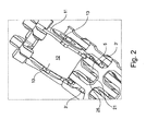
- FIG 1 details of the invention are illustrated in a sectional view of a conveyor belt.
- the inner section of the conveyor belt is illustrated and it is to be understood that the conveyor belt may have any desired width built up in a traditionally manner of constructing modular conveyor belts.
- figure 1 illustrates the under side of the conveyor belt in a section of the conveyor belt where a sprocket wheel 10 is engaging the conveyor belt 1.
- Each modular conveyor belt module 2 is interconnected by means of a connecting rod 3 such that adjacent modular beltings may pivot in a hinge-like manner relative to each other as indicated to the left in figure 1 where the modular conveyor belt is bend upwards.
- restrictor clips 5 Adjacent a side edge 4 of the conveyor belt is arranged restrictor clips 5 according to the invention.
- the restrictor clip 5 is provided in the apertures such that the movement of the connecting rod in elongated apertures provided in the eye parts 6 is severely limited whereby the sprockets 11 of the sprocket wheel 10 are able to firmly engage the exposed part 3' of the connecting rod in order to propel the conveyor belt 1.
- the sprocket wheel construction 10 comprises a main drum 12 and along the end peripheries of the main drum 12 is arranged sprocket teeth 11 which are shaped with a concave distal end 13 such that a firm engagement with the exposed part of the connecting pin 3' may be achieved in order to propel the conveyor belt 1.
- a large aperture 15 is provided in the sprocket wheel drum 12 where a drive axle connected to a motor may be inserted in order to rotate the sprocket wheel structure 10.
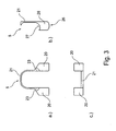
- FIG 3a), b) and c) illustrate the restrictor clip from various angles.
- the restrictor clip 5 is seen in plane view from above.
- the restrictor clip has a general U-shape where the distal ends of the parallel portions of the clip are provided with projecting members 20. Connecting the two projecting members 20 is a bridge section 21 which in use will be positioned adjacent the bottom of the space between two eye parts as illustrated in figure 2 .
- the projecting members 20 are provided with chamfered sections 23. These sections 23 are provided in order to accommodate enlarged eye portions 25 (see figure 2 ).
- the enlarged eye portions 25 are as already explained above provided in order to distribute the load on the eye part such that the assembled conveyor belt may be able to carry larger loads and distribute the load evenly along the connecting rod 3.
- connection section 21 has a substantially smaller cross section than the projecting members 20.
- the projecting members are dimensioned such that they will fit inside the apertures provided in the eye parts 25 of the modular belt links and are further provided with a concave outer section 26 and a convex inner section 27.
- the concave outer section 26 is provided in order to make the projecting member 20 fit snugly against the inside of the aperture whereas the inner convex section 27 is provided in order to accommodate a part of the periphery of the connecting rod 3 as both the restrictor clip and the connecting rod are inserted in an assembled conveyor belt as described above.
Landscapes
- Engineering & Computer Science (AREA)
- Mechanical Engineering (AREA)
- Structure Of Belt Conveyors (AREA)
Applications Claiming Priority (1)
| Application Number | Priority Date | Filing Date | Title |
|---|---|---|---|
| DKPA201000294A DK201000294A (en) | 2010-04-08 | 2010-04-08 | Restrictor clip |
Publications (2)
| Publication Number | Publication Date |
|---|---|
| EP2374739A1 EP2374739A1 (en) | 2011-10-12 |
| EP2374739B1 true EP2374739B1 (en) | 2012-12-05 |
Family
ID=44237897
Family Applications (1)
| Application Number | Title | Priority Date | Filing Date |
|---|---|---|---|
| EP11161437A Active EP2374739B1 (en) | 2010-04-08 | 2011-04-07 | Restrictor clip |
Country Status (3)
| Country | Link |
|---|---|
| US (1) | US8851271B2 (da) |
| EP (1) | EP2374739B1 (da) |
| DK (2) | DK201000294A (da) |
Families Citing this family (4)
| Publication number | Priority date | Publication date | Assignee | Title |
|---|---|---|---|---|
| CN105109681B (zh) * | 2015-09-16 | 2018-06-12 | 航宇救生装备有限公司 | 一种安装角可调的无人动力翼伞 |
| WO2017176846A1 (en) * | 2016-04-07 | 2017-10-12 | Laitram, L.L.C. | Drive and sideguard belt insert for a modular plastic conveyor belt |
| USD966882S1 (en) * | 2021-12-07 | 2022-10-18 | Wenzhou Xingyi Hardware Products Co., Ltd | Hinge angle restriction clip |
| USD972928S1 (en) * | 2021-12-07 | 2022-12-20 | Wenzhou Xingyi Hardware Products Co., Ltd | Hinge angle restriction clip |
Family Cites Families (8)
| Publication number | Priority date | Publication date | Assignee | Title |
|---|---|---|---|---|
| JPH06508812A (ja) * | 1991-07-03 | 1994-10-06 | ウエスタン アトラス インコーポレイテッド | 無圧力集積コンベヤ |
| WO1995028343A1 (en) * | 1994-04-15 | 1995-10-26 | Draebel Joergen | A conveyor chain having a supporting face constituted by chain links transversal to the longitudinal direction of the chain |
| US6345715B2 (en) * | 1998-11-03 | 2002-02-12 | Kvp Falcon Plastic Belting, Inc. | Rod retention system for modular plastic conveyor belt |
| US6484379B2 (en) * | 2001-03-16 | 2002-11-26 | Kvp Falcon Plastic Belting, Inc. | Method for radius limit adjustment on radius conveyor belts |
| US7108127B2 (en) * | 2003-07-24 | 2006-09-19 | Habasit Ag | Rod retaining snap rod with enlarged retaining ring |
| DE602005000619T2 (de) * | 2004-07-06 | 2007-06-21 | Laitram L.L.C. | Förderband und Förderbandmodul mit einem sich selbsteinstellenden Rand |
| US7494006B2 (en) * | 2005-06-07 | 2009-02-24 | Laitram, L.L.C. | Modular conveyor belts and attachments |
| US20100083466A1 (en) * | 2007-10-08 | 2010-04-08 | Kenneth Westergaard Andersen | Tri-yoke |
-
2010
- 2010-04-08 DK DKPA201000294A patent/DK201000294A/da not_active Application Discontinuation
-
2011
- 2011-04-07 EP EP11161437A patent/EP2374739B1/en active Active
- 2011-04-07 DK DK11161437.6T patent/DK2374739T3/da active
- 2011-04-08 US US13/082,838 patent/US8851271B2/en active Active
Also Published As
| Publication number | Publication date |
|---|---|
| US20120031739A1 (en) | 2012-02-09 |
| US8851271B2 (en) | 2014-10-07 |
| DK201000294A (en) | 2011-10-09 |
| DK2374739T3 (da) | 2013-03-18 |
| EP2374739A1 (en) | 2011-10-12 |
Similar Documents
| Publication | Publication Date | Title |
|---|---|---|
| US8007386B2 (en) | Blade tensioner with opposing spans | |
| US20080017483A1 (en) | Belt of a chain conveyor with innovative drive links | |
| EP2374739B1 (en) | Restrictor clip | |
| KR101659605B1 (ko) | 소팅 컨베이어 | |
| EP1277987B1 (en) | Alternating guide power transmission chain | |
| CN101438080B (zh) | 联接链条驱动的两段的链条张紧器件 | |
| EP2572120B1 (en) | Mechanical tensioner with one way damping | |
| EP2300733B1 (en) | Silent chain | |
| US9446805B2 (en) | Track assembly having arcuate crawler shoes | |
| US20070272523A1 (en) | Plate-link chain | |
| US20160052570A1 (en) | Track assembly having dual-sprocket drive wheel | |
| CA2871775A1 (en) | Conveyor belt with composite link | |
| KR20130058681A (ko) | 스윙 아암을 구비한 인장 장치 | |
| US20040118662A1 (en) | Curved conveyor | |
| US8657711B2 (en) | Silent chain having deformable guide plates | |
| US7452295B2 (en) | Chains for power transmission | |
| US9162829B2 (en) | Conveyor | |
| US4487013A (en) | T-rod chain | |
| EP1544503B1 (en) | A chain | |
| RU2207282C2 (ru) | Транспортное средство с катково-гусеничным движителем (варианты) | |
| JPS63285349A (ja) | Vベルト | |
| JPH01269744A (ja) | チェーン式動力伝動用ベルト | |
| JPH01288648A (ja) | チェーン式動力伝動用ベルト |
Legal Events
| Date | Code | Title | Description |
|---|---|---|---|
| PUAI | Public reference made under article 153(3) epc to a published international application that has entered the european phase |
Free format text: ORIGINAL CODE: 0009012 |
|
| AK | Designated contracting states |
Kind code of ref document: A1 Designated state(s): AL AT BE BG CH CY CZ DE DK EE ES FI FR GB GR HR HU IE IS IT LI LT LU LV MC MK MT NL NO PL PT RO RS SE SI SK SM TR |
|
| AX | Request for extension of the european patent |
Extension state: BA ME |
|
| 17P | Request for examination filed |
Effective date: 20120412 |
|
| GRAP | Despatch of communication of intention to grant a patent |
Free format text: ORIGINAL CODE: EPIDOSNIGR1 |
|
| RIC1 | Information provided on ipc code assigned before grant |
Ipc: B65G 17/08 20060101AFI20120521BHEP |
|
| GRAS | Grant fee paid |
Free format text: ORIGINAL CODE: EPIDOSNIGR3 |
|
| GRAA | (expected) grant |
Free format text: ORIGINAL CODE: 0009210 |
|
| AK | Designated contracting states |
Kind code of ref document: B1 Designated state(s): AL AT BE BG CH CY CZ DE DK EE ES FI FR GB GR HR HU IE IS IT LI LT LU LV MC MK MT NL NO PL PT RO RS SE SI SK SM TR |
|
| REG | Reference to a national code |
Ref country code: GB Ref legal event code: FG4D |
|
| REG | Reference to a national code |
Ref country code: CH Ref legal event code: EP |
|
| REG | Reference to a national code |
Ref country code: AT Ref legal event code: REF Ref document number: 587163 Country of ref document: AT Kind code of ref document: T Effective date: 20121215 |
|
| REG | Reference to a national code |
Ref country code: IE Ref legal event code: FG4D |
|
| REG | Reference to a national code |
Ref country code: DE Ref legal event code: R096 Ref document number: 602011000541 Country of ref document: DE Effective date: 20130131 |
|
| REG | Reference to a national code |
Ref country code: DK Ref legal event code: T3 |
|
| REG | Reference to a national code |
Ref country code: AT Ref legal event code: MK05 Ref document number: 587163 Country of ref document: AT Kind code of ref document: T Effective date: 20121205 |
|
| REG | Reference to a national code |
Ref country code: NL Ref legal event code: T3 |
|
| PG25 | Lapsed in a contracting state [announced via postgrant information from national office to epo] |
Ref country code: ES Free format text: LAPSE BECAUSE OF FAILURE TO SUBMIT A TRANSLATION OF THE DESCRIPTION OR TO PAY THE FEE WITHIN THE PRESCRIBED TIME-LIMIT Effective date: 20130316 Ref country code: FI Free format text: LAPSE BECAUSE OF FAILURE TO SUBMIT A TRANSLATION OF THE DESCRIPTION OR TO PAY THE FEE WITHIN THE PRESCRIBED TIME-LIMIT Effective date: 20121205 Ref country code: SE Free format text: LAPSE BECAUSE OF FAILURE TO SUBMIT A TRANSLATION OF THE DESCRIPTION OR TO PAY THE FEE WITHIN THE PRESCRIBED TIME-LIMIT Effective date: 20121205 Ref country code: NO Free format text: LAPSE BECAUSE OF FAILURE TO SUBMIT A TRANSLATION OF THE DESCRIPTION OR TO PAY THE FEE WITHIN THE PRESCRIBED TIME-LIMIT Effective date: 20130305 Ref country code: LT Free format text: LAPSE BECAUSE OF FAILURE TO SUBMIT A TRANSLATION OF THE DESCRIPTION OR TO PAY THE FEE WITHIN THE PRESCRIBED TIME-LIMIT Effective date: 20121205 |
|
| REG | Reference to a national code |
Ref country code: LT Ref legal event code: MG4D |
|
| PG25 | Lapsed in a contracting state [announced via postgrant information from national office to epo] |
Ref country code: LV Free format text: LAPSE BECAUSE OF FAILURE TO SUBMIT A TRANSLATION OF THE DESCRIPTION OR TO PAY THE FEE WITHIN THE PRESCRIBED TIME-LIMIT Effective date: 20121205 Ref country code: PL Free format text: LAPSE BECAUSE OF FAILURE TO SUBMIT A TRANSLATION OF THE DESCRIPTION OR TO PAY THE FEE WITHIN THE PRESCRIBED TIME-LIMIT Effective date: 20121205 Ref country code: SI Free format text: LAPSE BECAUSE OF FAILURE TO SUBMIT A TRANSLATION OF THE DESCRIPTION OR TO PAY THE FEE WITHIN THE PRESCRIBED TIME-LIMIT Effective date: 20121205 Ref country code: GR Free format text: LAPSE BECAUSE OF FAILURE TO SUBMIT A TRANSLATION OF THE DESCRIPTION OR TO PAY THE FEE WITHIN THE PRESCRIBED TIME-LIMIT Effective date: 20130306 |
|
| PG25 | Lapsed in a contracting state [announced via postgrant information from national office to epo] |
Ref country code: AT Free format text: LAPSE BECAUSE OF FAILURE TO SUBMIT A TRANSLATION OF THE DESCRIPTION OR TO PAY THE FEE WITHIN THE PRESCRIBED TIME-LIMIT Effective date: 20121205 |
|
| PG25 | Lapsed in a contracting state [announced via postgrant information from national office to epo] |
Ref country code: IS Free format text: LAPSE BECAUSE OF FAILURE TO SUBMIT A TRANSLATION OF THE DESCRIPTION OR TO PAY THE FEE WITHIN THE PRESCRIBED TIME-LIMIT Effective date: 20130405 Ref country code: EE Free format text: LAPSE BECAUSE OF FAILURE TO SUBMIT A TRANSLATION OF THE DESCRIPTION OR TO PAY THE FEE WITHIN THE PRESCRIBED TIME-LIMIT Effective date: 20121205 Ref country code: BE Free format text: LAPSE BECAUSE OF FAILURE TO SUBMIT A TRANSLATION OF THE DESCRIPTION OR TO PAY THE FEE WITHIN THE PRESCRIBED TIME-LIMIT Effective date: 20121205 Ref country code: CZ Free format text: LAPSE BECAUSE OF FAILURE TO SUBMIT A TRANSLATION OF THE DESCRIPTION OR TO PAY THE FEE WITHIN THE PRESCRIBED TIME-LIMIT Effective date: 20121205 Ref country code: RS Free format text: LAPSE BECAUSE OF FAILURE TO SUBMIT A TRANSLATION OF THE DESCRIPTION OR TO PAY THE FEE WITHIN THE PRESCRIBED TIME-LIMIT Effective date: 20121205 Ref country code: SK Free format text: LAPSE BECAUSE OF FAILURE TO SUBMIT A TRANSLATION OF THE DESCRIPTION OR TO PAY THE FEE WITHIN THE PRESCRIBED TIME-LIMIT Effective date: 20121205 Ref country code: BG Free format text: LAPSE BECAUSE OF FAILURE TO SUBMIT A TRANSLATION OF THE DESCRIPTION OR TO PAY THE FEE WITHIN THE PRESCRIBED TIME-LIMIT Effective date: 20130305 |
|
| PG25 | Lapsed in a contracting state [announced via postgrant information from national office to epo] |
Ref country code: RO Free format text: LAPSE BECAUSE OF FAILURE TO SUBMIT A TRANSLATION OF THE DESCRIPTION OR TO PAY THE FEE WITHIN THE PRESCRIBED TIME-LIMIT Effective date: 20121205 Ref country code: PT Free format text: LAPSE BECAUSE OF FAILURE TO SUBMIT A TRANSLATION OF THE DESCRIPTION OR TO PAY THE FEE WITHIN THE PRESCRIBED TIME-LIMIT Effective date: 20130405 |
|
| PLBE | No opposition filed within time limit |
Free format text: ORIGINAL CODE: 0009261 |
|
| STAA | Information on the status of an ep patent application or granted ep patent |
Free format text: STATUS: NO OPPOSITION FILED WITHIN TIME LIMIT |
|
| REG | Reference to a national code |
Ref country code: CH Ref legal event code: NV Representative=s name: FIAMMENGHI-FIAMMENGHI, CH |
|
| 26N | No opposition filed |
Effective date: 20130906 |
|
| PG25 | Lapsed in a contracting state [announced via postgrant information from national office to epo] |
Ref country code: MC Free format text: LAPSE BECAUSE OF FAILURE TO SUBMIT A TRANSLATION OF THE DESCRIPTION OR TO PAY THE FEE WITHIN THE PRESCRIBED TIME-LIMIT Effective date: 20121205 Ref country code: CY Free format text: LAPSE BECAUSE OF FAILURE TO SUBMIT A TRANSLATION OF THE DESCRIPTION OR TO PAY THE FEE WITHIN THE PRESCRIBED TIME-LIMIT Effective date: 20121205 |
|
| REG | Reference to a national code |
Ref country code: DE Ref legal event code: R097 Ref document number: 602011000541 Country of ref document: DE Effective date: 20130906 |
|
| REG | Reference to a national code |
Ref country code: IE Ref legal event code: MM4A |
|
| PG25 | Lapsed in a contracting state [announced via postgrant information from national office to epo] |
Ref country code: HR Free format text: LAPSE BECAUSE OF FAILURE TO SUBMIT A TRANSLATION OF THE DESCRIPTION OR TO PAY THE FEE WITHIN THE PRESCRIBED TIME-LIMIT Effective date: 20130731 |
|
| REG | Reference to a national code |
Ref country code: FR Ref legal event code: ST Effective date: 20131231 |
|
| PG25 | Lapsed in a contracting state [announced via postgrant information from national office to epo] |
Ref country code: FR Free format text: LAPSE BECAUSE OF NON-PAYMENT OF DUE FEES Effective date: 20130430 |
|
| PG25 | Lapsed in a contracting state [announced via postgrant information from national office to epo] |
Ref country code: IE Free format text: LAPSE BECAUSE OF NON-PAYMENT OF DUE FEES Effective date: 20130407 |
|
| PG25 | Lapsed in a contracting state [announced via postgrant information from national office to epo] |
Ref country code: MT Free format text: LAPSE BECAUSE OF FAILURE TO SUBMIT A TRANSLATION OF THE DESCRIPTION OR TO PAY THE FEE WITHIN THE PRESCRIBED TIME-LIMIT Effective date: 20121205 |
|
| PG25 | Lapsed in a contracting state [announced via postgrant information from national office to epo] |
Ref country code: SM Free format text: LAPSE BECAUSE OF FAILURE TO SUBMIT A TRANSLATION OF THE DESCRIPTION OR TO PAY THE FEE WITHIN THE PRESCRIBED TIME-LIMIT Effective date: 20121205 |
|
| PG25 | Lapsed in a contracting state [announced via postgrant information from national office to epo] |
Ref country code: TR Free format text: LAPSE BECAUSE OF FAILURE TO SUBMIT A TRANSLATION OF THE DESCRIPTION OR TO PAY THE FEE WITHIN THE PRESCRIBED TIME-LIMIT Effective date: 20121205 |
|
| PG25 | Lapsed in a contracting state [announced via postgrant information from national office to epo] |
Ref country code: HU Free format text: LAPSE BECAUSE OF FAILURE TO SUBMIT A TRANSLATION OF THE DESCRIPTION OR TO PAY THE FEE WITHIN THE PRESCRIBED TIME-LIMIT; INVALID AB INITIO Effective date: 20110407 Ref country code: LU Free format text: LAPSE BECAUSE OF NON-PAYMENT OF DUE FEES Effective date: 20130407 Ref country code: MK Free format text: LAPSE BECAUSE OF FAILURE TO SUBMIT A TRANSLATION OF THE DESCRIPTION OR TO PAY THE FEE WITHIN THE PRESCRIBED TIME-LIMIT Effective date: 20121205 |
|
| PG25 | Lapsed in a contracting state [announced via postgrant information from national office to epo] |
Ref country code: AL Free format text: LAPSE BECAUSE OF FAILURE TO SUBMIT A TRANSLATION OF THE DESCRIPTION OR TO PAY THE FEE WITHIN THE PRESCRIBED TIME-LIMIT Effective date: 20121205 |
|
| P01 | Opt-out of the competence of the unified patent court (upc) registered |
Effective date: 20230516 |
|
| PGFP | Annual fee paid to national office [announced via postgrant information from national office to epo] |
Ref country code: IT Payment date: 20230419 Year of fee payment: 13 Ref country code: DK Payment date: 20230427 Year of fee payment: 13 Ref country code: DE Payment date: 20230427 Year of fee payment: 13 Ref country code: CH Payment date: 20230502 Year of fee payment: 13 |
|
| PGFP | Annual fee paid to national office [announced via postgrant information from national office to epo] |
Ref country code: GB Payment date: 20230427 Year of fee payment: 13 |
|
| PGFP | Annual fee paid to national office [announced via postgrant information from national office to epo] |
Ref country code: NL Payment date: 20240426 Year of fee payment: 14 |