EP2374700A1 - Windshield attaching structure of vehicle - Google Patents
Windshield attaching structure of vehicle Download PDFInfo
- Publication number
- EP2374700A1 EP2374700A1 EP11161467A EP11161467A EP2374700A1 EP 2374700 A1 EP2374700 A1 EP 2374700A1 EP 11161467 A EP11161467 A EP 11161467A EP 11161467 A EP11161467 A EP 11161467A EP 2374700 A1 EP2374700 A1 EP 2374700A1
- Authority
- EP
- European Patent Office
- Prior art keywords
- shield
- windshield
- lock unit
- portions
- engaging
- Prior art date
- Legal status (The legal status is an assumption and is not a legal conclusion. Google has not performed a legal analysis and makes no representation as to the accuracy of the status listed.)
- Granted
Links
Images








Classifications
-
- B—PERFORMING OPERATIONS; TRANSPORTING
- B62—LAND VEHICLES FOR TRAVELLING OTHERWISE THAN ON RAILS
- B62J—CYCLE SADDLES OR SEATS; AUXILIARY DEVICES OR ACCESSORIES SPECIALLY ADAPTED TO CYCLES AND NOT OTHERWISE PROVIDED FOR, e.g. ARTICLE CARRIERS OR CYCLE PROTECTORS
- B62J17/00—Weather guards for riders; Fairings or stream-lining parts not otherwise provided for
- B62J17/02—Weather guards for riders; Fairings or stream-lining parts not otherwise provided for shielding only the rider's front
- B62J17/04—Windscreens
Definitions
- the present invention relates to a windshield attaching structure of a vehicle such as a motorcycle.
- JP-U Japanese Utility Model Application Laid-Open
- 3040432 discloses a configuration in which a holding member is provided to a windshield and is moved back and forth along a rail to manually change the inclination angle of the windshield.
- the portion which holds the inclination angle of the windshield is exposed from the center in the width direction of the vehicle body, with the result that the holding portion and the forward-arranged member (cover member or the like) of the motorcycle can complicate the front portion of the vehicle body of the motorcycle.
- an object of the present invention is to provide a windshield attaching structure which can change the inclination angle of a windshield to simplify the front portion of a vehicle body so that appearance can be improved.
- the present invention provides a windshield attaching structure of a windshield which is provided in the upper portion of the front portion of the vehicle body of a vehicle and reduces wind pressure to a driver, including a shield stay to which the windshield is attached, a rotation support shaft which supports the shield stay so as to be angle-shifted to a frame of the vehicle and a lock unit which can change the shield stay between a locked state in which the shield stay is locked in any one of a plurality of angle shift positions and an unlocked state in which the shield stay is not locked in any of the angle shift positions, wherein at least part of the lock unit is covered by a forward-arranged member arranged in the front portion of the vehicle.
- the windshield can be angle-shifted about the rotation support shaft together with the shield stay in the unlocked state. Therefore, the shield stay is changed from the locked state to the unlocked state, so that the driver can change the inclination angle of the windshield by gripping the windshield and can easily change the windshield to a desired inclination angle.
- the shield stay is changed from the unlocked state to the locked state, so that the changed inclined state of the windshield can be maintained.
- at least part of the lock unit is covered by the forward-arranged member.
- the forward-arranged member may be realized by, e.g., a meter cover, a front cowl, and a meter body.
- the present invention preferably includes the following configurations.
- the operating portion of the lock unit is operated by the driver.
- the shield stay can be changed between the locked state and the unlocked state.
- the operating portion is arranged in the position apart from the engaging portion of the shield stay engaged by the lock unit so as to be exposed from the forward-arranged member.
- the operating portion can be arranged in the position in which the operating portion can be easily operated by the driver. Even when the engaging portion of the shield stay is arranged in the position in which the engaging portion is difficult to be reached by the driver, the operability of the operating portion can be prevented from being deteriorated.
- the engaging portion can be arranged in an arbitrary position without considering the operability of the driver.
- the engaging portion can be easily provided in the position in which the engaging portion is covered by the forward-arranged member. In this way, while part of the lock unit (such as engaging portion) is arranged in the position in which part of the lock unit is covered by the forward-arranged member, the operability of the operating portion of the lock unit can be prevented from being deteriorated.
- the supporting portion is arranged toward the shield attaching portion from the engaging portion.
- the lock unit can be prevented from being located on the track of the angle shift of the shield stay with the supporting portion as a pivot, so that the interference between the lock unit and the shield stay can be prevented.
- the shield stay is engaged apart from the supporting portion. The moment force for engaging the shield stay can be larger to increase the engaging force of the lock unit.
- the lock unit is arranged so as to engage the engaging portion rearward of the supporting portion.
- Most of the lock unit can be easily arranged rearward of the rotation support shaft.
- the outer shape of the vehicle is typically increased in at least one of the vehicle width direction and the up and down direction rearward from the front end of the windshield. Therefore, the accommodating space becomes larger rearward in the region near the windshield.
- most of the lock unit is arranged rearward of the rotation support shaft.
- the lock unit can be arranged in the region in which the accommodating space is relatively large.
- the lock unit can be easily arranged so as to prevent the interference between the lock unit and other components, so that the degree of freedom of the design can be improved.
- the lock unit is arranged so as to engage the engaging portion downward of the supporting portion. Most of the lock unit can be easily arranged downward of the rotation support shaft. In this way, the lock unit is arranged downward of the rotation support shaft, so that part of the lock unit can be easily covered by the forward-arranged member to improve appearance.
- the front portion of the lock unit and the rotation support shaft are covered by the forward-arranged member.
- the front portion of the lock unit and the rotation support shaft can be prevented from being exposed outward to improve appearance.
- the supporting portion is arranged near each of a pair of forwardmost shield attaching portions.
- the angle shift of the shield stay with the supporting portion as a pivot cannot be inhibited by the shield attaching portion.
- the shield stays are supported by two right and left supporting portions, and are engaged with two right and left engaging portions by the lock unit.
- the shield stays can be stably supported.
- the distance between the engaging portions is larger than the distance between the supporting portions.
- the shield stays can be stably engaged.
- the lock and the unlock of each of the shield stays are enabled only by shifting the projecting portion between the locked position and the unlocked position.
- the configuration in which the lock unit locks the shield stay at a predetermined angle can be easily provided.
- the lock unit has the urging unit which urges the projecting portion in the direction engaging the engaging portion, and an operating lever for releasing the urging against the urging unit.
- the unlock of the shield stay without operating the lever can be prevented.
- the projecting portion can be held so as to engage the engaging portion.
- the windshield attaching structure which can change the inclination angle of the windshield to simplify the front portion of the vehicle body so that appearance can be improved can be provided.
- Fig. 1 is a left side view of a motorcycle 1 having a windshield attaching structure according to a first embodiment of the present invention. Further, the direction concept used in this embodiment coincides with the direction concept seen from the driver of the motorcycle 1.
- the motorcycle 1 has a front wheel 2 and a rear wheel 3, and the front wheel 2 is rotatably supported in the lower portion of a front fork 4 extended in the substantially up and down direction.
- the front fork 4 is supported by a steering shaft 7 via an upper bracket 5 provided at its upper end and an under bracket (not shown) provided downward of the upper bracket 5.
- the steering shaft 7 is rotatably supported by a head pipe 8.
- a bar type steering wheel 9 extended to right and left is attached to the upper bracket 5. Therefore, the driver swings the steering wheel 9 to right and left, so that the front wheel 2 is steered with the steering shaft 7 as a rotational shaft.
- a vehicle body frame 10 is extended rearward from the head pipe 8.
- a front end 11a of a swing arm 11 is axially supported at the rear lower end of the vehicle body frame 10.
- the rear wheel 3 is rotatably supported at the rear end of the swing arm 11.
- a fuel tank 12 is arranged upward of the vehicle body frame 10 and rearward of the steering wheel 9.
- a driver's seat 13 is arranged rearward of the fuel tank 12.
- An engine 14 is mounted substantially immediately below the fuel tank 12.
- a gear case 16 is arranged in the rear portion of a crankcase 15 of the engine 14, so that the power of the gear is transmitted to the rear wheel 3 via a chain (not shown).
- a head lamp 17 is arranged forward of the steering wheel 9, and is covered by a front cowl 18.
- the front cowl 18 is of a full cowl type in which its upper portion covers the head lamp 17 and its lower portion covers the engine 14 and the crankcase 15.
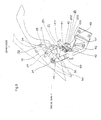
- Fig. 2 is an enlarged view of the upper portion in the front portion of the motorcycle 1 of Fig. 1 .
- Fig. 3 is a diagram of the motorcycle 1 seen from the driver.
- a meter body 51 having a display panel which displays the vehicle speed of the motorcycle 1 is arranged in the upper portion of the front cowl 18, and a meter cover 50 covers the upper portion in the front portion of the meter body 51.
- the meter cover 50 configures part of the upper surface of the front cowl 18.
- a windshield 19 which reduces wind pressure to the driver is arranged in the upper portion of the front cowl 18 and the meter cover 50.
- the windshield 19 is curved so as to have a convex shape forward, and is formed of a transparent resin plate to secure the forward visibility of the driver.
- Fig. 4 is a perspective view of the meter cover 50 portion from which the windshield 19 is removed.
- the meter cover 50 is formed so as to be separated into a rear cover 501 and a front cover 502 coupled to the rear cover 501 and arranged forward of the rear cover 501.
- a pair of right and left throughholes 501a extended in the front and rear direction and formed so that the rear ends thereof reach the rear end of the rear cover 501 are formed in the rear cover 501.
- a pair of right and left throughholes 502a extended in the front and rear direction and formed so that the rear ends thereof reach the rear end of the front cover 502 are formed in the front cover 502.
- the upper portions of shield stays 20 are inserted forward from the rear ends of the rear cover 501 and the front cover 502, so that the upper portions of the shield stays 20 can be attached so as to pass through the rear cover 501 and the front cover 502 upward.
- the length in the right and left direction of the throughholes 501a and 502a can be reduced.
- Fig. 5 is an enlarged left side view of the windshield 19 portion from which the front cowl 18, the meter cover 50, the meter body 51 and the like are removed.
- Fig. 6 is a rear perspective view of the windshield attaching structure from which the windshield 19 is detached.
- the windshield 19 is attached to a pair of right and left shield stays 20.
- the pair of right and left shield stays 20 are coupled by a coupling member 60 extended in the right and left direction.
- the coupling member 60 couples the outermost portions in the right and left direction of the shield stays 20.
- the shield stays 20 are attached to right and left rotation support shafts 30 located at the ends of a center stay 101.
- the center stay 101 is bolted and fixed onto the head pipe 8 formed at the front end of the vehicle body frame 10.
- a lock unit 40 is provided downward and rearward of the shield stays 20, so that the shield stays 20 can be locked in a plurality of angle shift positions.
- the rotation support shafts 30 have axes extended in the horizontal direction and support the shield stays 20 so that the shield stays 20 can be angle-shifted about the axes. Therefore, in the state that the lock unit 40 is unlocked, the shield stays 20 and the windshield 19 can be angle-shifted about the axes of the rotation support shafts 30.
- An upper pipe 102 extended in the right and left direction is attached to the center stay 101.
- Mirror brackets 103 for attaching rear-view mirrors are attached to the right and left ends of the upper pipe 102.
- a meter stay 104 to which the meter body 51 is attached is welded and fixed to the center portion in the right and left direction of the upper pipe 102.
- the lock unit 40 is located downward of the meter stay 104.
- the meter cover 50 which covers the meter body 51 attached to the meter stay 104 covers the rotation support shafts 30 and the upper portion and the front portion of the lock unit 40.
- Later-described shield attaching portions 23 are projected upward from the upper surface of the meter cover 50.
- the windshield 19 is attached to the shield attaching portions 23.
- the shield stays 20 have engaging portions 21, supporting portions 22, and the shield attaching portions 23, respectively.
- the lock unit 40 locks the shield stays 20 at a predetermined angle.
- the supporting portions 22 are supported so as to be angle-shifted by the rotation support shafts 30 about the axes of the rotation support shafts 30.
- the shield stays 20 can be angle-shifted about the rotation support shafts 30 with respect to the center stay 101, that is, the vehicle body frame 10.
- the engaging portions 21 are portions engaged by the abutment of part of the lock unit 40.
- the lock unit 40 is abutted onto the engaging portions 21, so that the shield stays 20 are brought into a locked state in which the angle shift about the axes of the rotation support shafts 30 is inhibited.
- the abutment of the lock unit 40 onto the engaging portions 21 is released, so that the shield stays 20 are brought into an unlocked state in which the angle shift is allowed.
- part of the lock unit 40 is changed between the state that part of the lock unit 40 is abutted onto the engaging portions 21 and the state that part of the lock unit 40 is not abutted onto the engaging portions 21, so that the shield stays 20 can be changed between the locked state in which the shield stays 20 are locked at the predetermined angle and the unlocked state.
- Screws 24 can be attached to the shield attaching portions 23.
- the windshield 19 and the shield attaching portions 23 are fastened by the screws 24 from the front surface side of the windshield 19, so that the windshield 19 is attached to the shield stays 20.
- a plurality of pairs of right and left shield attaching portions 23 are provided according to the pair of right and left shield stays 20, and are provided so as to be spaced from each other in the front and rear direction.
- Fig. 6 three pairs of shield attaching portions 23 are provided.
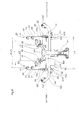
- Fig. 7 is a front view of the windshield attaching structure of Fig. 6 .
- Fig. 8 is a rear view of the windshield attaching structure of Fig. 6 .
- the supporting portions 22 are arranged near a pair of forwardmost shield attaching portions 23a.
- An interval L1 in the right and left direction of the pair of forwardmost shield attaching portions 23a is shorter than an interval L2 in the right and left direction of the pair of middle shield attaching portions 23 and an interval L3 in the right and left direction of the pair of rear shield attaching portions 23.
- the engaging portions 21 are provided rearward of the supporting portions 22 and downward of the supporting portions 22.
- the supporting portions 22 are arranged toward the shield attaching portions 23 from the engaging portions 21.
- the supporting portions 22 are arranged toward the forwardmost shield attaching portions 23a.
- the supporting portions 22 are formed so as to be extended inward in the right and left direction and rearward and downward from the forwardmost shield attaching portions 23a, and branching portions 26 are formed so as to be extended rearward and outward in the right and left direction from the supporting portions 22 and branched in the up and down direction.
- the engaging portions 21 are provided in the position in which the engaging portions 21 are extended downward from the branching portions 26, and the remaining shield attaching portions 23 are provided in the position in which the remaining shield attaching portions 23 are extended upward from the branching portions 26.
- the shield stays 20 may be configured by joining a plurality of element members.
- first element members having the forwardmost shield attaching portions 23a and the supporting portions 22 and second element members having the engaging portions 21 and the remaining shield attaching portions 23 may be welded so as to be configured as the shield stays 20 as a whole. Further, the second element members may be configured by fastening the engaging portions 21 and the remaining shield attaching portions 23.
- an interval L4 in the right and left direction of the pair of engaging portions 21 is formed so as to be larger than an interval L5 in the right and left direction of the pair of supporting portions 22.
- the pair of engaging portions 21 are arranged in the outermost side portions of the right and left shield stays 20 with respect to the right and left direction.
- the pair of supporting portions 22 are arranged in the innermost side portions of the right and left shield stays 20 with respect to the right and left direction.
- the coupling member 60 which is extended in the right and left direction and couples the pair of engaging portions 21 is provided, so that the strength of the engaging portions 21 can be improved.
- the engaging portions 21 have a pair of right and left plural teeth 211 engaged by projecting portions 41 of the lock unit 40.
- the plural teeth 211 are provided so that the shield stays 20 can be fixed in the plurality of angle shift positions.
- the projecting portions 41 of the lock unit 40 are located in a locked position in which the projecting portions 41 are engaged with recess portions 25 between the teeth 211 so as to hold the shield stays 20 in the predetermined angle shift position.
- the projecting portions 41 of the lock unit 40 are moved into an unlocked position rearward of the recess portions 25, the recess portions 25 and the projecting portions 41 are disengaged to enable the angle shift of the shield stays 20.
- the plurality of teeth 211 are formed at the substantially rear ends of the shield stays 20, so that the projecting portions 41 of the lock unit 40 are located rearward of the shield stays 20.
- the plurality of teeth 211 are formed so as to be arranged side by side in the substantially up and down direction. Regardless of the inclination angle of the shield stays 20, the distances in which the projecting portions 41 are moved between the locked position and the unlocked position are substantially constant, so that the operability of the lock unit 40 can be improved.
- four teeth 211 are provided on each of the right and left sides, and the projecting portions 41 of the lock unit 40 are engaged with the recess portions 25 (three on each of the right and left sides) formed by the teeth 211, so that the shield stays 20 can be located in three angle shift positions.
- each of the recess portions 25 engaged by each of the projecting portions 41 of the lock unit 40 is shifted upward or downward by one tooth (for instance, the projecting portion 41 of the lock unit 40 engaged with a recess portion 251 is engaged with a recess portion 252)
- the inclination angle of the windshield 19 is changed by 5 to 10 degrees.
- the alternate long and two short dashes line of Fig. 5 shows the state that the projecting portion 41 of the lock unit 40 engaged with the recess portion 251 is engaged with a recess portion 253 so that the inclination of the windshield 19 is changed from the minimum inclination angle to the maximum inclination angle.
- the windshield 19 can be angle-shifted by 15 to 30 degrees at a maximum.
- the minimum inclination angle of the windshield 19 is about 30 degrees
- the inclination angle of the windshield 19 is changed by 30 to 60 degrees.
- the lock unit 40 has a body portion 401 extended in the right and left direction along the coupling member 60, ends 402 provided at the right and left ends of the body portion 401 and having the projecting portions 41, and an operating lever 43 extended rearward from the body portion 401.
- Supporting portions 403 supported by the upper pipe 102 are attached to the pair of right and left ends 402, respectively.
- the supporting portions 403 support the ends 402 so as to be rotated about axes parallel with the rotation support shafts 30.
- the ends 402, the lever 43, and the body portion 401 are integrally configured.
- the lever 43 and the projecting portions 41 are provided on the sides opposite each other in the front and rear direction with respect to the supporting portions 403.
- the lock unit 40 is supported by the upper pipe 102.
- a bracket which supports the lock unit 40 is not required to be additionally provided, so that the number of components can be reduced.
- the rotation support shafts 30 are fixed to the center stay 101 which supports the upper pipe 102. Brackets which fix the rotation support shafts 30 are not required to be additionally provided, so that the number of components can be reduced. In this way, the rotation support shafts 30 and the lock unit 40 are supported by the existing components, so that the number of components can be reduced.
- the projecting portions 41 are engaged with the recess portions 25 of the engaging portions 21 of the shield stays 20, and the projecting portions 41 are engaged with the recess portions 25, so that the shield stays 20 are fixed at the predetermined angle.
- an urging unit 42 realized by springs are provided at the ends 402, respectively, and urge the projecting portions 41 in the direction engaging the projecting portions 41 with the recess portions 25 (in the front direction of the vehicle body).
- the lever 43 is extended rearward from the rear ends of the shield stays 20, and passes downward of the upper pipe 102.
- An end 431 of the lever 43 is located rearward of the meter body 51.
- the lock unit 40 has the lever 43 which becomes an operating portion manually operated to change between the locked state and the unlocked state, and the lever 43 is arranged in the position apart from the engaging portions 21 which are engaged with the angle shift of the shield stays 20.
- the lever 43 is arranged in the position in which the lever 43 is exposed from the meter cover 50.
- the lever 43 is arranged downward of the meter cover 50 and the steering wheel 9, so that the lever 43 can be prevented from being noticeable.
- the shield stays 20 are rotatable about the rotation support shafts 30.
- the shield stays 20 are rotated forward about the rotation support shafts 30.
- the inclination angle of the shield stays 20 is increased, and according to that, the inclination angle of the windshield 19 attached to the shield stays 20 is increased.
- the engaging portions 21 are also rotated in an R direction about the rotation support shafts 30.
- the recess portions 25 formed by the teeth 211 provided to the engaging portions 21 are also rotated in the R direction about the rotation support shafts 30.
- the urging unit 42 engage the projecting portions 41 with the recess portions 253 located downward of the recess portions 251. As a result, the shield stays 20 are fixed in the different angle shift position, so that the windshield 19 is fixed in the state that its inclination angle is increased.
- the pair of right and left shield stays 20 are provided, and are coupled by the coupling member 60.
- the pair of right and left shield stays 20 are not required to be provided, and may be, for instance, integrated in the middle portion.
- the shield stays 20 preferably have the plurality of shield attaching portions 23.
- the plurality of pairs of right and left shield attaching portions 23 are preferably provided so as to be spaced from each other in the front and rear direction.
- the engaging portions 21 have the plural teeth 211, and the projecting portions 41 of the lock unit 40 are engaged with the recess portions 25 formed by the teeth 211.
- the inclination angle of the shield stays 20 is changed stepwise.
- the engaging portions 21 and the lock unit 40 may be configured so that the inclination angle of the shield stays 20 is continuously changed.
- the lock unit grips and fixes the rotated engaging portions 21.
- the inclination angle of the shield stays 20 can be continuously changed.
- the recess portions 25 are formed to the engaging portions 21 of the shield stays 20, and the projecting portions 41 are formed to the lock unit 40.
- the projecting portions may be formed to the engaging portions 21 of the shield stays 20, and the recess portions may be formed to the lock unit 40.
- the recess portions are formed to either the shield stays 20 or the lock unit 40, and the convex portions (projecting portions) are formed to the other.
- the shield stay 20 can be changed between the locked state and the unlocked state.
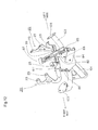
- Fig. 9 is a rear perspective view of the windshield attaching structure according to a second embodiment of the present invention.
- Fig. 10 is a partially rear view of Fig. 9
- Fig. 11 is a partially rear perspective view of Fig. 9 .
- This embodiment and the first embodiment are the same except that the configurations and arrangements of the rotation support shafts, the coupling member, and the lock unit are different. For this reason, in the description of this embodiment, the same components and portions as the first embodiment are indicated by the same reference numerals, and the detailed descriptions of their contents are omitted.
- the pair of right and left shield stays 20 are coupled by a coupling member 71.
- the coupling member 71 is attached to the upper pipe 102.
- a cam portion 711 is provided at one end in the right and left direction (at the right end in this embodiment) of the coupling member 71.
- a rotating member 72 rotated about an axis of the coupling member 71 is arranged rightward and outward of the cam portion 711.
- a cam portion 721 of the rotating member 72 can be engaged with the cam portion 711.
- the rotating member 72 has a gripping portion 722 extended in the radius direction of the coupling member 71.
- the gripping portion 722 is rotated about an axis of the coupling member 71 to change the engaging state of the cam portion 711 and the cam portion 721, so that the distance in the right and left direction between the cam portion 711 and the cam portion 721 can be changed.
- Fig. 9 shows the state that the cam portion 711 and the cam portion 721 are completely engaged with each other and the distance in the right and left direction between the cam portion 711 and the cam portion 721 is minimum.
- Figs. 10 and 11 show the state that the rotating member 72 is rotated, the engagement of the cam portion 711 and the cam portion 721 is released, and the distance in the right and left direction between the cam portion 711 and the cam portion 721 is extended.
- the shield stay 20 is located rightward and outward of the cam portion 721, and a screw 73 fastens the shield stay 20 and the rotating member 72 to the coupling member 71 from the rightward and outward sides of the shield stay 20.
- a long hole 201 is formed in the fastening portion of the shield stay 20 by the screw 73.
- the position of the screw 73 in the long hole 201 is changed, so that the angle shift position of the shield stay 20 can be changed.
- the gripping portion 722 of the rotating member 72 is rotated about an axis of the coupling member 71.
- the cam portion 721 is rotated about an axis of the coupling member 71.
- the cam portion 711 and the cam portion 721 are disengaged, so that the distance in the right and left direction between the cam portion 711 and the cam portion 721 is extended.
- the screw 73 When the distance in the right and left direction between the cam portion 711 and the cam portion 721 is extended, the screw 73 is pressed rightward and outward, the screw 73 can be moved in the long hole 201 of the shield stay 20, and the shield stays 20 can be angle-shifted. Then, the position of the screw 73 in the long hole 201 is changed, so that the shield stays 20 are in the desired angle shift position. Thereafter, the rotating member 72 is rotated in the opposite direction of the first-time rotating direction. As a result, the engaged state of the cam portion 711 and the cam portion 721 is changed (the cam portion 711 and the cam portion 721 are brought into the completely engaged state), so that the distance in the right and left direction between the cam portion 711 and the cam portion 721 is shortened.
- the screw 73 fastens the shield stays 20 to the coupling member 71.
- the shield stays 20 are fixed into the different angle shift portion, so that the windshield 19 is fixed in the state that its inclination angle is changed.
- the inclination angle of the windshield 19 is changed by the shield stays 20, the coupling member 71, the rotating member 72, and the screw 73.
- the simplified windshield attaching structure can be provided.
- the coupling member 71, the rotating member 72, and the screw 73 are covered by the meter cover 50. Appearance can be maintained satisfactory
- the long hole 201 is formed in the fastening portion of the shield stay 20 by the screw 73.
- the screw 73 can be continuously moved in the long hole 201, so that the shield stays 20 can be continuously angle-shifted.
- Fig. 12 is a front perspective view of the windshield attaching structure according to a third embodiment of the present invention
- Fig. 13 is a left side view of Fig. 12 .
- This embodiment and the first embodiment are the same except that the configurations and arrangements of the rotation support shafts, the coupling member, and the lock unit are different. For this reason, in the description of this embodiment, the same components and portions as the first embodiment are indicated by the same reference numerals, and the detailed descriptions of their contents are omitted.
- the pair of right and left shield stays 20 are coupled by a coupling member 81.
- the coupling member 81 is coupled to a first engaging member 83 at a pivot 84 via an arm 82.
- the first engaging member 83 can be rotated with respect to the center stay 101 about a pivot 831.
- the first engaging member 83 can be engaged with a second engaging member 85.
- the second engaging member 85 can be rotated with respect to the center stay 101 about a pivot 851.
- the pair of right and left shield stays 20 are coupled to the center stay 101 by resilient members 86 provided one on each of the right and left sides.
- a pressing member 87 has a lower end which can press down a front end 852 of the second engaging member 85.
- an urging member 853 urges the second engaging member 85 in an X direction to reinforce the engagement of the first engaging member 83 and the second engaging member 85.
- the pressing member 87 is pressed down to rotate the second engaging member 85 in the opposite direction of the X direction about the pivot 851 against the urging force of the urging member 853.
- the second engaging member 85 is rotated in the opposite direction of the X direction, the first engaging member 83 and the second engaging member 85 are disengaged from each other.
- the first engaging member 83 and the second engaging member 85 When the first engaging member 83 and the second engaging member 85 are disengaged from each other, the first engaging member 83 can be rotated about the pivot 831.
- the first engaging member 83 and the shield stays 20 are coupled at a pivot 84 and a pivot 811 via the arm 82, so that the first engaging member 83 is rotated about the pivot 831 to angle-shift the shield stays 20. As a result, the inclination angle of the windshield 19 attached to the shield stays 20 is changed.
- the pressing member 87 When the inclination angle of the windshield 19 is determined, the pressing member 87 is pulled up. The pressing of the second engaging member 85 by the pressing member 87 is released, the second engaging member 85 is rotated in the X direction about the pivot 851 by the urging member 853, and is engaged with the first engaging member 83. Then, the first engaging member 83 is fixed to the center stay 101. As a result, the shield stays 20 are fixed in the different angle shift position, so that the windshield 19 is fixed in the state that its inclination angle is changed.
- the inclination angle of the windshield 19 is changed by the coupling member 81, the arm 82, the first engaging member 83, the second engaging member 85, and the pressing member 87.
- the simplified windshield attaching structure can be provided.
- the coupling member 81, the arm 82, the first engaging member 83, and the second engaging member 85 are covered by the meter cover 50. Appearance can be held satisfactory.
- the first engaging member 83 is rotated about the pivot 831 to angle-shift the shield stays 20.
- the rotation angle of the first engaging member 83 about the pivot 831 can be continuously changed, so that the shield stays 20 can be continuously angle-shifted.
- Fig. 14 is a front perspective view of the windshield attaching structure according to a fourth embodiment of the present invention.
- This embodiment and the first embodiment are the same except that the configurations and arrangements of the coupling member and the lock unit are different. For this reason, in the description of this embodiment, the same components and portions as the first embodiment are indicated by the same reference numerals, and the detailed descriptions of their contents are omitted.
- the pair of right and left shield stays 20 are coupled by the coupling member 60.
- a bolt 91 having a ring-like head is attached to the coupling member 60.
- a screw portion 911 of the bolt 91 is gripped by a gripping member 92 from the right and left sides.
- the gripping member 92 is attached to the center stay 101.
- the position in the up and down direction of the screw portion 911 gripped by the gripping member 92 is changed, so that the bolt 91 is moved up and down with respect to the center stay 101.
- the coupling member 60 gripped by a ring portion 912 of the bolt 91 is moved up and down with respect to the center stay 101.
- the shield stays 20 are angle-shifted with respect to the center stay 101 about the rotation support shafts 30.
- Fig. 15 is a lower perspective view of the gripping member 92 portion of Fig. 14 .
- the gripping member 92 has a gripping portion 921 and a gripping portion 922 which grip the screw portion 911 of the bolt 91 from the right and left sides.
- the gripping portion 921 and the gripping portion 922 are covered by a cover 923.
- Fig. 16 is a diagram showing the gripping member 92 of Fig. 15 from which the cover 923 is detached.
- the gripping portion 921 and the gripping portion 922 are urged by an urging member 927 in the direction gripping the screw portion 911.
- the gripping member 92 has a pulley member 925 which can change the interval of the gap between the gripping portion 921 and the gripping portion 922.
- a wire 924 is wound around the pulley member 925.
- An eccentric member 926 is provided in the position rearward of the pulley member 925 and sandwiched between the gripping portion 921 and the gripping portion 922. The wire 924 is pulled in a Y direction, so that the eccentric member 926 can be rotated about a pivot 925a of the pulley member 925.
- the eccentric member 926 has a substantially elliptical shape having a short axis and a long axis in front view.
- Fig. 17 is a schematic diagram of the gripping member 92 of Fig. 15 in the state that the pulley member 925 is removed, viewed in the direction of an arrow XVII.
- Fig. 18 is a diagram showing the state that the eccentric member 926 of Fig. 17 is rotated about the pivot 925a. As shown in Fig. 17 , in the state that the gripping portion 921 and the gripping portion 922 grip the screw portion 911, the short axis portion of the eccentric member 926 is sandwiched between the gripping portion 921 and the gripping portion 922.
- the wire 924 is pulled in the Y direction, as shown in Fig.
- the eccentric member 926 is rotated about the pivot 925a, so that the longer portion than the short axis portion of the eccentric member 926 is sandwiched between the gripping portion 921 and the gripping portion 922.
- the gap between the gripping portion 921 and the gripping portion 922 is extended against the urging of the urging member 927, so that the gripped state of the screw portion 911 by the gripping portion 921 and the gripping portion 922 is released.
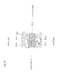
- Fig. 19 is a perspective view of the gripping portion 921. Since the gripping portion 922 has the same configuration as that of the gripping portion 921, the gripping portion 921 will be described as an example.
- the gripping portion 921 has a female screw portion 921a engaged with the screw portion 911 formed with a male screw, and convex portions 921b and hole portions 921c engaged with the gripping portion 922.
- the convex portions 921b and the hole portions 921c are provided one on each of the front and rear sides of the female screw portion 921a, and are staggered with respect to each other in the front and rear direction of the female screw portion 921a.
- the screw portion 911 is formed with a male screw and the female screw portion 921a is formed with a female screw, so that the gripping portion 921 can substantially continuously (at a thread pitch) change the gripping position of the screw portion 911 in the axis direction (that is, in the up and down direction) of the screw portion 911.
- the convex portions 921b of the gripping portion 921 are engaged with the hole portions of the gripping portion 922, and the convex portions of the gripping portion 922 are engaged with the hole portion 921c of the gripping portion 921. In the engagement of the gripping portion 921 and the gripping portion 922, the positioning of the gripping portion 921 and the gripping portion 922 can be easily performed.
- the wire 924 is pulled in the Y direction to rotate the eccentric member 926 about the pivot 925a.
- the gap between the gripping portion 921 and the gripping portion 922 which grip the screw portion 911 of the bolt 91 is increased to release the gripped state of the screw portion 911.
- the bolt 91 When the gripped state of the screw portion 911 is released, the bolt 91 can be moved in the up and down direction to move the bolt 91 in the up and down direction.
- the coupling member 60 By the movement of the bolt 91 in the up and down direction, the coupling member 60 is moved up and down with respect to the center stay 101.
- the shield stays 20 are angle-shifted with respect to the center stay 101 about the rotation support shafts 30, and according to that, the inclination angle of the windshield 19 attached to the shield stays 20 is changed.
- the inclination angle of the windshield 19 is changed by the shield stays 20, the coupling member 60, the bolt 91, and the gripping member 92.
- the simplified windshield attaching structure can be provided.
- the coupling member 60, the bolt 91, and the gripping member 92 are covered by the meter cover 50. Appearance can be held satisfactory.
- the up and down position of the bolt 91 is changed to angle-shift the shield stays 20.
- the gripped position of the bolt 91 by the gripping member 92 can be changed substantially continuously in the up and down direction, so that the shield stays 20 can be continuously angle-shifted.
- the cover member which covers the rotation support shafts 30, the coupling member 60, the lock unit 40 and the like is the meter cover 50.
- the cover member is not limited to the meter cover 50, and may be the cover member arranged in the front portion of the vehicle body, e.g., the front cowl 18. Such cover member is formed into a non-transparent shape, so that the lock unit 40 and the like can be prevented from being noticeable.
- the cover member preferably covers at least the front portion of the lock unit 40 and the like.
- the meter cover 50 arranged rearward of the end of the windshield 19 and forward of the steering wheel 9 covers the lock unit 40 and the like. The present invention is not limited to this.
- Part of the lock unit 40 and the like may be covered by the forward-arranged member other than the meter cover arranged forward of the viewpoint of the driver. Even in a vehicle in which the front cowl 18 and the meter cover 50 are not provided, the meter body 51 may cover, as the forward-arranged member, the lock unit 40 and the like.
- the lock unit 40 and the like is arranged in the region forward of the meter body, preferably, in the region forward and downward thereof, more preferably, in the region on the opposite side of the visibility of the meter body 51 with respect to the visibility direction connecting the viewpoint of the driver and the meter body 51.
- at least part of the lock unit 40 and the like is preferably arranged in the region forward and downward of the steering wheel 9 and the upper bracket 5.
- At least part of the lock unit 40 is covered by the forward-arranged member.
- at least part of the lock unit 40 is covered by the forward-arranged member to simplify the front portion of the vehicle body so that appearance can be improved.
- the lever 43 and the like is used as the operating portion which changes the shield stays 20 between the locked state and the unlocked state.
- a power transmission mechanism which provides power for changing the locked state in the position apart from the engaging portions 21, it may be used as the operating portion.
- the operating portion and the engaging portions 21 are spaced from each other, and using a typical mechanism such as a gear and a belt, power may be transmitted from the operating portion to the engaging portions 21.
- electric power may be used as power for the change between the locked state and the unlocked state, and a switch for providing an electric power instruction may be used as the operating portion.
- an electromagnetic solenoid may be used as the lock unit.
- the present invention has been described using the motorcycle.
- all vehicles having a windshield forward of a driver are applicable.
- the present invention can be suitably used for saddle type vehicles such as small planing boats, buggy vehicles, and all-terrain vehicles.
- the present invention is suitably applicable to vehicles having a windshield forward of the handlebar of a vehicle.
- part of the lock unit and the rotation support shafts are arranged forward and downward of the handlebar. Part of the lock unit and the rotation support shafts are hidden from the visibility of the driver, so that appearance can be improved.
- the windshield attaching structure which can change the inclination angle of the windshield to simplify the front portion of the vehicle body so that appearance can be improved can be provided, the industrial utilization value is high.
Landscapes
- Engineering & Computer Science (AREA)
- Mechanical Engineering (AREA)
- Body Structure For Vehicles (AREA)
- Instrument Panels (AREA)
Abstract
Description
- The present invention relates to a windshield attaching structure of a vehicle such as a motorcycle.
- A conventional windshield attached to the upper portion of a front cowl which covers the front portion of the vehicle body of a motorcycle can change its inclination angle in some cases. For instance, Japanese Utility Model Application Laid-Open (JP-U) No.
3040432 - However, in the windshield attaching structure in
Patent Document 1, the portion which holds the inclination angle of the windshield is exposed from the center in the width direction of the vehicle body, with the result that the holding portion and the forward-arranged member (cover member or the like) of the motorcycle can complicate the front portion of the vehicle body of the motorcycle. - Accordingly, an object of the present invention is to provide a windshield attaching structure which can change the inclination angle of a windshield to simplify the front portion of a vehicle body so that appearance can be improved.
- The present invention provides a windshield attaching structure of a windshield which is provided in the upper portion of the front portion of the vehicle body of a vehicle and reduces wind pressure to a driver, including a shield stay to which the windshield is attached, a rotation support shaft which supports the shield stay so as to be angle-shifted to a frame of the vehicle and a lock unit which can change the shield stay between a locked state in which the shield stay is locked in any one of a plurality of angle shift positions and an unlocked state in which the shield stay is not locked in any of the angle shift positions, wherein at least part of the lock unit is covered by a forward-arranged member arranged in the front portion of the vehicle.
- According to the above configuration, the windshield can be angle-shifted about the rotation support shaft together with the shield stay in the unlocked state. Therefore, the shield stay is changed from the locked state to the unlocked state, so that the driver can change the inclination angle of the windshield by gripping the windshield and can easily change the windshield to a desired inclination angle. In addition, in the state that the inclination angle of the windshield is changed, the shield stay is changed from the unlocked state to the locked state, so that the changed inclined state of the windshield can be maintained. Further, in the present invention, at least part of the lock unit is covered by the forward-arranged member. When the driver riding in the vehicle sees the front, at least part of the lock unit is covered by the forward-arranged member to simplify the front portion of the vehicle body so that appearance can be improved. The forward-arranged member may be realized by, e.g., a meter cover, a front cowl, and a meter body.
- Furthermore, the present invention preferably includes the following configurations.
- (1) The lock unit has an operating portion which is manually operated to change the shield stay between the locked state and the unlocked state, wherein the operating portion is arranged in the position apart from an engaging portion of the shield stay engaged by the lock unit so as to be exposed from the forward-arranged member.
- (2) In the configuration (1), the shield stay further has a supporting portion supported by the rotation support shaft and a shield attaching portion fixed to the windshield, wherein the supporting portion is arranged toward the shield attaching portion from the engaging portion.
- (3) In the configuration (2), the lock unit locks the engaging portion rearward of the supporting portion.
- (4) In the configuration (2) or (3), the lock unit locks the engaging portion downward of the supporting portion.
- (5) The front portion of the lock unit and the rotation support shaft are covered by the forward-arranged member.
- (6) In any one of the configurations (2) to (4), a plurality of shield attaching portions are provided so as to be spaced from each other in the front and rear direction, wherein the supporting portion is arranged near the forwardmost shield attaching portion.
- (7) In any one of the configurations (2) to (4), and (6), a pair of right and left shield stays are provided, wherein each of the shield stays has the engaging portion and the supporting portion, and wherein the distance in the right and left direction between the right and left engaging portions is set to be larger than the distance in the right and left direction between the right and left supporting portions.
- (8) In any one of the configurations (2) to (4), (6), and (7), the engaging portion has a plurality of teeth for angle shift positioning, wherein the lock unit has a projecting portion which can be shifted between a locked position and an unlocked position, wherein the projecting portion is shifted into the locked position so as to be engaged with one of recess portions formed by the teeth of the engaging portion so that the lock unit locks the shield stay into the predetermined angle shift position, and wherein the projecting portion is shifted into the unlocked position to disengage the projecting portion and the engaging portion from each other so that the lock unit unlocks the shield stay.
- (9) In the configuration (8), the lock unit has an urging unit which urges the projecting portion in the direction engaging the engaging portion, and an operating lever which releases the urging against the urging unit.
- According to the configuration (1), the operating portion of the lock unit is operated by the driver. The shield stay can be changed between the locked state and the unlocked state. In addition, the operating portion is arranged in the position apart from the engaging portion of the shield stay engaged by the lock unit so as to be exposed from the forward-arranged member. The operating portion can be arranged in the position in which the operating portion can be easily operated by the driver. Even when the engaging portion of the shield stay is arranged in the position in which the engaging portion is difficult to be reached by the driver, the operability of the operating portion can be prevented from being deteriorated. Further, the engaging portion can be arranged in an arbitrary position without considering the operability of the driver. The engaging portion can be easily provided in the position in which the engaging portion is covered by the forward-arranged member. In this way, while part of the lock unit (such as engaging portion) is arranged in the position in which part of the lock unit is covered by the forward-arranged member, the operability of the operating portion of the lock unit can be prevented from being deteriorated.
- According to the configuration (2), the supporting portion is arranged toward the shield attaching portion from the engaging portion. The lock unit can be prevented from being located on the track of the angle shift of the shield stay with the supporting portion as a pivot, so that the interference between the lock unit and the shield stay can be prevented. In addition, as compared with when the shield stay is engaged near the supporting portion, the shield stay is engaged apart from the supporting portion. The moment force for engaging the shield stay can be larger to increase the engaging force of the lock unit.
- According to the configuration (3), the lock unit is arranged so as to engage the engaging portion rearward of the supporting portion. Most of the lock unit can be easily arranged rearward of the rotation support shaft. The outer shape of the vehicle is typically increased in at least one of the vehicle width direction and the up and down direction rearward from the front end of the windshield. Therefore, the accommodating space becomes larger rearward in the region near the windshield. In the present invention, as described above, most of the lock unit is arranged rearward of the rotation support shaft. As compared with when the lock unit is arranged forward of the rotation support shaft, the lock unit can be arranged in the region in which the accommodating space is relatively large. The lock unit can be easily arranged so as to prevent the interference between the lock unit and other components, so that the degree of freedom of the design can be improved.
- According to the configuration (4), the lock unit is arranged so as to engage the engaging portion downward of the supporting portion. Most of the lock unit can be easily arranged downward of the rotation support shaft. In this way, the lock unit is arranged downward of the rotation support shaft, so that part of the lock unit can be easily covered by the forward-arranged member to improve appearance.
- According to the configuration (5), the front portion of the lock unit and the rotation support shaft are covered by the forward-arranged member. The front portion of the lock unit and the rotation support shaft can be prevented from being exposed outward to improve appearance.
- According to the configuration (6), the supporting portion is arranged near each of a pair of forwardmost shield attaching portions. The angle shift of the shield stay with the supporting portion as a pivot cannot be inhibited by the shield attaching portion.
- According to the configuration (7), the shield stays are supported by two right and left supporting portions, and are engaged with two right and left engaging portions by the lock unit. The shield stays can be stably supported. In addition, the distance between the engaging portions is larger than the distance between the supporting portions. The shield stays can be stably engaged.
- According to the configuration (8), the lock and the unlock of each of the shield stays are enabled only by shifting the projecting portion between the locked position and the unlocked position. The configuration in which the lock unit locks the shield stay at a predetermined angle can be easily provided.
- According to the configuration (9), the lock unit has the urging unit which urges the projecting portion in the direction engaging the engaging portion, and an operating lever for releasing the urging against the urging unit. The unlock of the shield stay without operating the lever can be prevented. In addition, when the lever is not operated by the urging unit, the projecting portion can be held so as to engage the engaging portion.
- In short, according to the present invention, the windshield attaching structure which can change the inclination angle of the windshield to simplify the front portion of the vehicle body so that appearance can be improved can be provided.
-
-
Fig. 1 is a left side view of a motorcycle having a windshield attaching structure according to a first embodiment of the present invention; -
Fig. 2 is an enlarged view of the upper portion in the front portion of the motorcycle ofFig. 1 ; -
Fig. 3 is a diagram of the motorcycle seen from a driver; -
Fig. 4 is a perspective view of a meter cover portion from which a windshield is removed; -
Fig. 5 is an enlarged left side view of the windshield portion; -
Fig. 6 is a rear perspective view of the windshield attaching structure from which the windshield is detached; -
Fig. 7 is a front view of the windshield attaching structure ofFig. 6 ; -
Fig. 8 is a rear view of the windshield attaching structure ofFig. 6 ; -
Fig. 9 is a rear perspective view of the windshield attaching structure according to a second embodiment of the present invention; -
Fig. 10 is a partially rear view ofFig. 9 ; -
Fig. 11 is a partially rear perspective view ofFig. 9 ; -
Fig. 12 is a front perspective view of the windshield attaching structure according to a third embodiment of the present invention; -
Fig. 13 is a left side view ofFig. 12 ; -
Fig. 14 is a front perspective view of the windshield attaching structure according to a fourth embodiment of the present invention; -
Fig. 15 is a lower perspective view of a grippingmember 92 portion ofFig.14 ; -
Fig. 16 is a diagram showing the grippingmember 92 ofFig. 15 from which acover 923 is detached; -
Fig. 17 is a schematic diagram of the grippingmember 92 ofFig. 15 in the state that apulley member 925 is removed, viewed in the direction of an arrow XVII; -
Fig. 18 is a diagram showing the state that aneccentric member 926 ofFig. 17 is rotated about apivot 925a; and -
Fig. 19 is a perspective view of agripping portion 921. -
Fig. 1 is a left side view of amotorcycle 1 having a windshield attaching structure according to a first embodiment of the present invention. Further, the direction concept used in this embodiment coincides with the direction concept seen from the driver of themotorcycle 1. - As shown in
Fig. 1 , themotorcycle 1 has afront wheel 2 and arear wheel 3, and thefront wheel 2 is rotatably supported in the lower portion of afront fork 4 extended in the substantially up and down direction. Thefront fork 4 is supported by asteering shaft 7 via anupper bracket 5 provided at its upper end and an under bracket (not shown) provided downward of theupper bracket 5. The steeringshaft 7 is rotatably supported by ahead pipe 8. A bartype steering wheel 9 extended to right and left is attached to theupper bracket 5. Therefore, the driver swings thesteering wheel 9 to right and left, so that thefront wheel 2 is steered with thesteering shaft 7 as a rotational shaft. - A
vehicle body frame 10 is extended rearward from thehead pipe 8. Afront end 11a of aswing arm 11 is axially supported at the rear lower end of thevehicle body frame 10. Therear wheel 3 is rotatably supported at the rear end of theswing arm 11. Afuel tank 12 is arranged upward of thevehicle body frame 10 and rearward of thesteering wheel 9. A driver'sseat 13 is arranged rearward of thefuel tank 12. Anengine 14 is mounted substantially immediately below thefuel tank 12. Agear case 16 is arranged in the rear portion of acrankcase 15 of theengine 14, so that the power of the gear is transmitted to therear wheel 3 via a chain (not shown). - A
head lamp 17 is arranged forward of thesteering wheel 9, and is covered by afront cowl 18. Thefront cowl 18 is of a full cowl type in which its upper portion covers thehead lamp 17 and its lower portion covers theengine 14 and thecrankcase 15. -
Fig. 2 is an enlarged view of the upper portion in the front portion of themotorcycle 1 ofFig. 1 .Fig. 3 is a diagram of themotorcycle 1 seen from the driver. As shown inFigs. 2 and3 , ameter body 51 having a display panel which displays the vehicle speed of themotorcycle 1 is arranged in the upper portion of thefront cowl 18, and ameter cover 50 covers the upper portion in the front portion of themeter body 51. In addition, themeter cover 50 configures part of the upper surface of thefront cowl 18. Awindshield 19 which reduces wind pressure to the driver is arranged in the upper portion of thefront cowl 18 and themeter cover 50. - The
windshield 19 is curved so as to have a convex shape forward, and is formed of a transparent resin plate to secure the forward visibility of the driver. -
Fig. 4 is a perspective view of themeter cover 50 portion from which thewindshield 19 is removed. As shown inFig. 4 , themeter cover 50 is formed so as to be separated into arear cover 501 and afront cover 502 coupled to therear cover 501 and arranged forward of therear cover 501. A pair of right and left throughholes 501a extended in the front and rear direction and formed so that the rear ends thereof reach the rear end of therear cover 501 are formed in therear cover 501. Likewise, a pair of right and left throughholes 502a extended in the front and rear direction and formed so that the rear ends thereof reach the rear end of thefront cover 502 are formed in thefront cover 502. Thereby, the upper portions of shield stays 20 are inserted forward from the rear ends of therear cover 501 and thefront cover 502, so that the upper portions of the shield stays 20 can be attached so as to pass through therear cover 501 and thefront cover 502 upward. As compared with when the upper portions of the shield stays 20 are attached so as to pass through the throughholes 501a of therear cover 501 and the throughholes 502a of thefront cover 502 upward from the lower side, the length in the right and left direction of the throughholes 501a and 502a can be reduced. -
Fig. 5 is an enlarged left side view of thewindshield 19 portion from which thefront cowl 18, themeter cover 50, themeter body 51 and the like are removed.Fig. 6 is a rear perspective view of the windshield attaching structure from which thewindshield 19 is detached. As shown inFigs. 5 and6 , thewindshield 19 is attached to a pair of right and left shield stays 20. The pair of right and left shield stays 20 are coupled by acoupling member 60 extended in the right and left direction. Thecoupling member 60 couples the outermost portions in the right and left direction of the shield stays 20. The shield stays 20 are attached to right and leftrotation support shafts 30 located at the ends of acenter stay 101. Thecenter stay 101 is bolted and fixed onto thehead pipe 8 formed at the front end of thevehicle body frame 10. Alock unit 40 is provided downward and rearward of the shield stays 20, so that the shield stays 20 can be locked in a plurality of angle shift positions. - The
rotation support shafts 30 have axes extended in the horizontal direction and support the shield stays 20 so that the shield stays 20 can be angle-shifted about the axes. Therefore, in the state that thelock unit 40 is unlocked, the shield stays 20 and thewindshield 19 can be angle-shifted about the axes of therotation support shafts 30. - An
upper pipe 102 extended in the right and left direction is attached to thecenter stay 101.Mirror brackets 103 for attaching rear-view mirrors are attached to the right and left ends of theupper pipe 102. Ameter stay 104 to which themeter body 51 is attached is welded and fixed to the center portion in the right and left direction of theupper pipe 102. - The
lock unit 40 is located downward of themeter stay 104. As apparent fromFigs. 2 to 5 , themeter cover 50 which covers themeter body 51 attached to themeter stay 104 covers therotation support shafts 30 and the upper portion and the front portion of thelock unit 40. Later-describedshield attaching portions 23 are projected upward from the upper surface of themeter cover 50. Thewindshield 19 is attached to theshield attaching portions 23. - Hereinafter, the configurations of the shield stays 20 and the
lock unit 40 will be described in more detail. - As shown in
Fig. 6 , the shield stays 20 have engagingportions 21, supportingportions 22, and theshield attaching portions 23, respectively. In the engagingportions 21, thelock unit 40 locks the shield stays 20 at a predetermined angle. The supportingportions 22 are supported so as to be angle-shifted by therotation support shafts 30 about the axes of therotation support shafts 30. The shield stays 20 can be angle-shifted about therotation support shafts 30 with respect to thecenter stay 101, that is, thevehicle body frame 10. The engagingportions 21 are portions engaged by the abutment of part of thelock unit 40. Thelock unit 40 is abutted onto the engagingportions 21, so that the shield stays 20 are brought into a locked state in which the angle shift about the axes of therotation support shafts 30 is inhibited. In addition, the abutment of thelock unit 40 onto the engagingportions 21 is released, so that the shield stays 20 are brought into an unlocked state in which the angle shift is allowed. In this way, part of thelock unit 40 is changed between the state that part of thelock unit 40 is abutted onto the engagingportions 21 and the state that part of thelock unit 40 is not abutted onto the engagingportions 21, so that the shield stays 20 can be changed between the locked state in which the shield stays 20 are locked at the predetermined angle and the unlocked state.Screws 24 can be attached to theshield attaching portions 23. Thewindshield 19 and theshield attaching portions 23 are fastened by thescrews 24 from the front surface side of thewindshield 19, so that thewindshield 19 is attached to the shield stays 20. A plurality of pairs of right and leftshield attaching portions 23 are provided according to the pair of right and left shield stays 20, and are provided so as to be spaced from each other in the front and rear direction. For instance, inFig. 6 , three pairs ofshield attaching portions 23 are provided.Fig. 7 is a front view of the windshield attaching structure ofFig. 6 .Fig. 8 is a rear view of the windshield attaching structure ofFig. 6 . The supportingportions 22 are arranged near a pair of forwardmostshield attaching portions 23a. An interval L1 in the right and left direction of the pair of forwardmostshield attaching portions 23a is shorter than an interval L2 in the right and left direction of the pair of middleshield attaching portions 23 and an interval L3 in the right and left direction of the pair of rearshield attaching portions 23. The engagingportions 21 are provided rearward of the supportingportions 22 and downward of the supportingportions 22. - In the side view of the
motorcycle 1, that is, in the state that themotorcycle 1 is projected onto a plane vertical to the axes of therotation support shafts 30, the supportingportions 22 are arranged toward theshield attaching portions 23 from the engagingportions 21. In this embodiment, the supportingportions 22 are arranged toward the forwardmostshield attaching portions 23a. Thereby, thelock unit 40 abutted onto the engagingportions 21 are not located on the track of the angle shift of the shield stays 20 with the supportingportions 22 as pivots. - In the shield stays 20, the supporting
portions 22 are formed so as to be extended inward in the right and left direction and rearward and downward from the forwardmostshield attaching portions 23a, and branchingportions 26 are formed so as to be extended rearward and outward in the right and left direction from the supportingportions 22 and branched in the up and down direction. In the shield stays 20, the engagingportions 21 are provided in the position in which the engagingportions 21 are extended downward from the branchingportions 26, and the remainingshield attaching portions 23 are provided in the position in which the remainingshield attaching portions 23 are extended upward from the branchingportions 26. The shield stays 20 may be configured by joining a plurality of element members. For instance, first element members having the forwardmostshield attaching portions 23a and the supportingportions 22 and second element members having the engagingportions 21 and the remainingshield attaching portions 23 may be welded so as to be configured as the shield stays 20 as a whole. Further, the second element members may be configured by fastening the engagingportions 21 and the remainingshield attaching portions 23. - By the above configuration, an interval L4 in the right and left direction of the pair of engaging
portions 21 is formed so as to be larger than an interval L5 in the right and left direction of the pair of supportingportions 22. In addition, the pair of engagingportions 21 are arranged in the outermost side portions of the right and left shield stays 20 with respect to the right and left direction. Further, the pair of supportingportions 22 are arranged in the innermost side portions of the right and left shield stays 20 with respect to the right and left direction. Thecoupling member 60 which is extended in the right and left direction and couples the pair of engagingportions 21 is provided, so that the strength of the engagingportions 21 can be improved. - As shown in
Figs. 5 and6 , the engagingportions 21 have a pair of right and leftplural teeth 211 engaged by projectingportions 41 of thelock unit 40. Theplural teeth 211 are provided so that the shield stays 20 can be fixed in the plurality of angle shift positions. The projectingportions 41 of thelock unit 40 are located in a locked position in which the projectingportions 41 are engaged withrecess portions 25 between theteeth 211 so as to hold the shield stays 20 in the predetermined angle shift position. In addition, when the projectingportions 41 of thelock unit 40 are moved into an unlocked position rearward of therecess portions 25, therecess portions 25 and the projectingportions 41 are disengaged to enable the angle shift of the shield stays 20. The plurality ofteeth 211 are formed at the substantially rear ends of the shield stays 20, so that the projectingportions 41 of thelock unit 40 are located rearward of the shield stays 20. The plurality ofteeth 211 are formed so as to be arranged side by side in the substantially up and down direction. Regardless of the inclination angle of the shield stays 20, the distances in which the projectingportions 41 are moved between the locked position and the unlocked position are substantially constant, so that the operability of thelock unit 40 can be improved. In this embodiment, fourteeth 211 are provided on each of the right and left sides, and the projectingportions 41 of thelock unit 40 are engaged with the recess portions 25 (three on each of the right and left sides) formed by theteeth 211, so that the shield stays 20 can be located in three angle shift positions. When the position of each of therecess portions 25 engaged by each of the projectingportions 41 of thelock unit 40 is shifted upward or downward by one tooth (for instance, the projectingportion 41 of thelock unit 40 engaged with arecess portion 251 is engaged with a recess portion 252), the inclination angle of thewindshield 19 is changed by 5 to 10 degrees. The alternate long and two short dashes line ofFig. 5 shows the state that the projectingportion 41 of thelock unit 40 engaged with therecess portion 251 is engaged with arecess portion 253 so that the inclination of thewindshield 19 is changed from the minimum inclination angle to the maximum inclination angle. In this case, thewindshield 19 can be angle-shifted by 15 to 30 degrees at a maximum. Here, when the minimum inclination angle of thewindshield 19 is about 30 degrees, the inclination angle of thewindshield 19 is changed by 30 to 60 degrees. - As shown in
Fig. 6 , thelock unit 40 has abody portion 401 extended in the right and left direction along thecoupling member 60, ends 402 provided at the right and left ends of thebody portion 401 and having the projectingportions 41, and an operatinglever 43 extended rearward from thebody portion 401. Supportingportions 403 supported by theupper pipe 102 are attached to the pair of right and left ends 402, respectively. The supportingportions 403 support theends 402 so as to be rotated about axes parallel with therotation support shafts 30. The ends 402, thelever 43, and thebody portion 401 are integrally configured. Thelever 43 and the projectingportions 41 are provided on the sides opposite each other in the front and rear direction with respect to the supportingportions 403. When thelever 43 is rotated, the projectingportions 41 are shifted with the rotation of thelever 43. Thelock unit 40 is supported by theupper pipe 102. A bracket which supports thelock unit 40 is not required to be additionally provided, so that the number of components can be reduced. Likewise, therotation support shafts 30 are fixed to the center stay 101 which supports theupper pipe 102. Brackets which fix therotation support shafts 30 are not required to be additionally provided, so that the number of components can be reduced. In this way, therotation support shafts 30 and thelock unit 40 are supported by the existing components, so that the number of components can be reduced. As described above, the projectingportions 41 are engaged with therecess portions 25 of the engagingportions 21 of the shield stays 20, and the projectingportions 41 are engaged with therecess portions 25, so that the shield stays 20 are fixed at the predetermined angle. In addition, as shown inFigs. 5 and6 , an urgingunit 42 realized by springs are provided at theends 402, respectively, and urge the projectingportions 41 in the direction engaging the projectingportions 41 with the recess portions 25 (in the front direction of the vehicle body). As a result, when the projectingportions 41 are engaged with therecess portions 25, the projectingportions 41 are not disengaged from therecess portions 25 unless an external force is applied. Thelever 43 is extended rearward from the rear ends of the shield stays 20, and passes downward of theupper pipe 102. Anend 431 of thelever 43 is located rearward of themeter body 51. When the driver presses down theend 431 of thelever 43 against the urgingunit 42, the urging of the projectingportions 41 by the urgingunit 42 is released, so that the projectingportions 41 can be disengaged from therecess portions 25. As a result, the fixing of the shield stays 20 is released, so that the shield stays 20 can be angle-shifted about therotation support shafts 30. - In this way, the
lock unit 40 has thelever 43 which becomes an operating portion manually operated to change between the locked state and the unlocked state, and thelever 43 is arranged in the position apart from the engagingportions 21 which are engaged with the angle shift of the shield stays 20. Thelever 43 is arranged in the position in which thelever 43 is exposed from themeter cover 50. In this embodiment, thelever 43 is arranged downward of themeter cover 50 and thesteering wheel 9, so that thelever 43 can be prevented from being noticeable. - Hereinafter, an operation of angle-shifting the shield stays 20 to adjust the inclination angle of the
windshield 19 will be described. - The following operation of changing the
windshield 19 in the state shown by the solid line ofFig. 5 to thewindshield 19 shown by the alternate long and two short dashes line ofFig. 5 , that is, of increasing the inclination angle of thewindshield 19, is performed. - First, the
end 431 of thelever 43 is pressed down to release the urging of the projectingportions 41 by the urgingunit 42. Then, the projectingportions 41 are disengaged from therecess portions 251. - When the projecting
portions 41 are disengaged from therecess portions 251, the shield stays 20 are rotatable about therotation support shafts 30. The shield stays 20 are rotated forward about therotation support shafts 30. As a result, the inclination angle of the shield stays 20 is increased, and according to that, the inclination angle of thewindshield 19 attached to the shield stays 20 is increased. - According to the forward rotation of the shield stays 20, the engaging
portions 21 are also rotated in an R direction about therotation support shafts 30. As a result, therecess portions 25 formed by theteeth 211 provided to the engagingportions 21 are also rotated in the R direction about therotation support shafts 30. - The urging
unit 42 engage the projectingportions 41 with therecess portions 253 located downward of therecess portions 251. As a result, the shield stays 20 are fixed in the different angle shift position, so that thewindshield 19 is fixed in the state that its inclination angle is increased. - When the inclination angle of the
windshield 19 is decreased, the opposite operation of the above operation may be performed. - According to this embodiment, the following effects can be exhibited.
- (1) The inclination angle of the
windshield 19 is changed by the shield stays 20, therotation support shafts 30, and thelock unit 40. The simplified windshield attaching structure can be provided. In addition, therotation support shafts 30 and thelock unit 40 are covered by themeter cover 50. Appearance can be maintained satisfactory. -
- (2) The
lever 43 is provided in the position apart from the engagingportions 21 of the shield stays 20 so as to be exposed from themeter cover 50. The position of thelever 43 can be arranged in the position in which thelever 43 can be easily operated by the driver. Even when the engagingportions 21 of the shield stays 20 are arranged in the position in which the engagingportions 21 are difficult to be reached by the driver, the operation of changing the shield stays 20 between the locked state and the unlocked state can be easily performed. In addition, the engagingportions 21 can be arranged in any position without considering the driver's operability. The engagingportions 21 can be easily arranged in the position in which the engagingportions 21 are covered by themeter cover 50. In this way, while part of thelock unit 40 is covered by themeter cover 50, the driver's operability of thelever 43 can be secured. -
- (3) The supporting
portions 22 are arranged toward theshield attaching portions 23 from the engagingportions 21. Thelock unit 40 can be prevented from being located on the track of the angle shift of the shield stays 20 with the supportingportions 22 as pivots, so that the interference between thelock unit 40 and the shield stays 20 can be prevented. In addition, the engagingportions 21 are arranged so as to be apart from the supportingportions 22. As compared with when the shield stays 20 are engaged near the supportingportions 22, the shield stays 20 are engaged apart from the supportingportions 22. The moment force for engaging the shield stays 20 can be larger to increase the engaging force of thelock unit 40. -
- (4) The
lock unit 40 is arranged so as to engage the engagingportions 21 rearward of the supportingportions 22. Most of thelock unit 40 can be easily arranged rearward of therotation support shafts 30. In this embodiment, thelock unit 40 is arranged rearward of the inner region of thefront cowl 18 downward of thewindshield 19. As compared with when thelock unit 40 is arranged forward of the inside of thefront cowl 18, thelock unit 40 can be easily accommodated. Thefront cowl 18 of themotorcycle 1 is typically formed into a streamlined shape in which the outer shape vertical to the front and rear direction is increased from the front side toward the rear side. Therefore, in the inner region of thefront cowl 18 downward of thewindshield 19, the accommodating space in the up and down direction and in the right and left direction is larger on the rear side than on the front side. In this embodiment, as described above, most of thelock unit 40 is arranged rearward of therotation support shafts 30. As compared with when thelock unit 40 is arranged forward of therotation support shafts 30, thelock unit 40 can be arranged rearward of thefront cowl 18 having a relatively large accommodating space. Thelock unit 40 can be easily arranged so as to prevent the interference between thelock unit 40 and other components, so that the degree of freedom of the design can be improved. -
- (5) The
lock unit 40 is arranged so as to be engaged with the engagingportions 21 downward of the supportingportions 22. Most of thelock unit 40 can be easily arranged downward of therotation support shafts 30. In this way, thelock unit 40 is arranged downward of therotation support shafts 30, so that part of thelock unit 40 can be easily covered by themeter cover 50. Thelock unit 40 cannot be noticeable from the driver's seat, so that appearance can be improved. In addition, therotation support shafts 30 and the front portion of thelock unit 40 are covered by themeter cover 50. Therotation support shafts 30 and the front portion of thelock unit 40 can be prevented from being exposed outward, so that appearance can be improved. -
- (6) The
lock unit 40 is arranged rearward and downward of the supportingportions 22. The angle shift of the shield stays 20 with the supportingportions 22 as pivots cannot be inhibited by thelock unit 40. In addition, the engagingportions 21 are apart from the supportingportions 22. As compared with when the supportingportions 22 are engaged by thelock unit 40, the shield stays 20 are engaged apart from the supportingportions 22. The moment force for engaging the shield stays 20 can be larger to increase the engaging force of thelock unit 40. -
- (7) The shield stays 20 are supported by two right and left supporting
portions 22, and are engaged by thelock unit 40 at two right and left engagingportions 21. The shield stays 20 can be stably supported. In addition, the distance between the engagingportions 21 is larger than the distance between the supportingportions 22. The shield stays 20 can be stably engaged. -
- (8) The supporting
portions 22 are arranged near the pair of forwardmostshield attaching portions 23a. The angle shift of the shield stays 20 with the supportingportions 22 as pivots cannot be inhibited by theshield attaching portions 23. -
- (9) The engaging
portions 21 have theplural teeth 211, and the projectingportions 41 of thelock unit 40 are engaged with therecess portions 25 formed by theteeth 211, so that thelock unit 40 locks the shield stays 20. The configuration in which thelock unit 40 locks the shield stays 20 at the predetermined angle can be easily provided. -
- (10) The position of the
recess portions 25 engaged by the projectingportions 41 is changed to change the inclination angle of the shield stays 20. As compared with when a knob shown inPatent Document 1 is rotated, the inclination angle of the shield stays 20 can be changed more easily. -
- (11) The
lock unit 40 has the urgingunit 42 which urge the projectingportions 41 in the direction engaging the engagingportions 21, and thelever 43 which releases the urging. The unlock without operating thelever 43 can be prevented. In addition, thelock unit 40 has the urgingunit 42, so that when thelever 43 is not operated, the projectingportions 41 can be held so as to be engaged with the engagingportions 21. -
- (12) The
lever 43 is formed so as to be extended rearward of the shield stays 20, and theend 431 of thelever 43 is located rearward of the meter body. The driver can easily operate thelever 43, that is, the driver can easily release the urging of the urgingunit 42. -
- (13) The
coupling member 60 couples the outermost portions in the right and left direction of the right and left shield stays 20. The rigidity of the right and left shield stays 20 integrated with thecoupling member 60 can be improved. -
- (14) The plurality of pairs of the
shield attaching portions 23 are provided so as to be spaced from each other in the front and rear direction, and the interval in the right and left direction of the pair of forwardmostshield attaching portions 23a is shorter than the intervals in the right and left direction of other pairs ofshield attaching portions 23. That is, the supporting interval of thewindshield 19 is shorter on the front side of the vehicle body than on the rear side of the vehicle body. Since thewindshield 19 receives wind from the front side of the vehicle body, with the above supporting intervals of thewindshield 19, the shield stays 20 can stably support thewindshield 19. - In this embodiment, the pair of right and left shield stays 20 are provided, and are coupled by the
coupling member 60. However, the pair of right and left shield stays 20 are not required to be provided, and may be, for instance, integrated in the middle portion. Also in this case, the shield stays 20 preferably have the plurality ofshield attaching portions 23. The plurality of pairs of right and leftshield attaching portions 23 are preferably provided so as to be spaced from each other in the front and rear direction. - In this embodiment, the engaging
portions 21 have theplural teeth 211, and the projectingportions 41 of thelock unit 40 are engaged with therecess portions 25 formed by theteeth 211. The inclination angle of the shield stays 20 is changed stepwise. However, the engagingportions 21 and thelock unit 40 may be configured so that the inclination angle of the shield stays 20 is continuously changed. For instance, the lock unit grips and fixes the rotated engagingportions 21. The inclination angle of the shield stays 20 can be continuously changed. - In addition, in this embodiment, the
recess portions 25 are formed to the engagingportions 21 of the shield stays 20, and the projectingportions 41 are formed to thelock unit 40. Without being limited to this, the projecting portions may be formed to the engagingportions 21 of the shield stays 20, and the recess portions may be formed to thelock unit 40. In this way, the recess portions are formed to either the shield stays 20 or thelock unit 40, and the convex portions (projecting portions) are formed to the other. The shield stay 20 can be changed between the locked state and the unlocked state. -
Fig. 9 is a rear perspective view of the windshield attaching structure according to a second embodiment of the present invention.Fig. 10 is a partially rear view ofFig. 9 , andFig. 11 is a partially rear perspective view ofFig. 9 . This embodiment and the first embodiment are the same except that the configurations and arrangements of the rotation support shafts, the coupling member, and the lock unit are different. For this reason, in the description of this embodiment, the same components and portions as the first embodiment are indicated by the same reference numerals, and the detailed descriptions of their contents are omitted. - The pair of right and left shield stays 20 are coupled by a
coupling member 71. Thecoupling member 71 is attached to theupper pipe 102. Acam portion 711 is provided at one end in the right and left direction (at the right end in this embodiment) of thecoupling member 71. A rotatingmember 72 rotated about an axis of thecoupling member 71 is arranged rightward and outward of thecam portion 711. Acam portion 721 of the rotatingmember 72 can be engaged with thecam portion 711. The rotatingmember 72 has agripping portion 722 extended in the radius direction of thecoupling member 71. The grippingportion 722 is rotated about an axis of thecoupling member 71 to change the engaging state of thecam portion 711 and thecam portion 721, so that the distance in the right and left direction between thecam portion 711 and thecam portion 721 can be changed.Fig. 9 shows the state that thecam portion 711 and thecam portion 721 are completely engaged with each other and the distance in the right and left direction between thecam portion 711 and thecam portion 721 is minimum. On the other hand,Figs. 10 and 11 show the state that the rotatingmember 72 is rotated, the engagement of thecam portion 711 and thecam portion 721 is released, and the distance in the right and left direction between thecam portion 711 and thecam portion 721 is extended. - As shown in
Fig. 10 , theshield stay 20 is located rightward and outward of thecam portion 721, and ascrew 73 fastens theshield stay 20 and the rotatingmember 72 to thecoupling member 71 from the rightward and outward sides of theshield stay 20. - As shown in
Fig. 11 , along hole 201 is formed in the fastening portion of the shield stay 20 by thescrew 73. The position of thescrew 73 in thelong hole 201 is changed, so that the angle shift position of the shield stay 20 can be changed. - Hereinafter, an operation of angle-shifting the shield stays 20 to adjust the inclination angle of the
windshield 19 will be described. - First, the gripping
portion 722 of the rotatingmember 72 is rotated about an axis of thecoupling member 71. As a result, thecam portion 721 is rotated about an axis of thecoupling member 71. When thecam portion 721 is rotated, thecam portion 711 and thecam portion 721 are disengaged, so that the distance in the right and left direction between thecam portion 711 and thecam portion 721 is extended. - When the distance in the right and left direction between the
cam portion 711 and thecam portion 721 is extended, thescrew 73 is pressed rightward and outward, thescrew 73 can be moved in thelong hole 201 of theshield stay 20, and the shield stays 20 can be angle-shifted. Then, the position of thescrew 73 in thelong hole 201 is changed, so that the shield stays 20 are in the desired angle shift position. Thereafter, the rotatingmember 72 is rotated in the opposite direction of the first-time rotating direction. As a result, the engaged state of thecam portion 711 and thecam portion 721 is changed (thecam portion 711 and thecam portion 721 are brought into the completely engaged state), so that the distance in the right and left direction between thecam portion 711 and thecam portion 721 is shortened. - When the distance in the right and left direction between the
cam portion 711 and thecam portion 721 is shortened, thescrew 73 fastens the shield stays 20 to thecoupling member 71. As a result, the shield stays 20 are fixed into the different angle shift portion, so that thewindshield 19 is fixed in the state that its inclination angle is changed. - According to this embodiment, the following effects can be exhibited.
- The inclination angle of the
windshield 19 is changed by the shield stays 20, thecoupling member 71, the rotatingmember 72, and thescrew 73. The simplified windshield attaching structure can be provided. In addition, thecoupling member 71, the rotatingmember 72, and thescrew 73 are covered by themeter cover 50. Appearance can be maintained satisfactory - The
long hole 201 is formed in the fastening portion of the shield stay 20 by thescrew 73. Thescrew 73 can be continuously moved in thelong hole 201, so that the shield stays 20 can be continuously angle-shifted. -
Fig. 12 is a front perspective view of the windshield attaching structure according to a third embodiment of the present invention, andFig. 13 is a left side view ofFig. 12 . This embodiment and the first embodiment are the same except that the configurations and arrangements of the rotation support shafts, the coupling member, and the lock unit are different. For this reason, in the description of this embodiment, the same components and portions as the first embodiment are indicated by the same reference numerals, and the detailed descriptions of their contents are omitted. - The pair of right and left shield stays 20 are coupled by a
coupling member 81. Thecoupling member 81 is coupled to a first engagingmember 83 at apivot 84 via anarm 82. The first engagingmember 83 can be rotated with respect to the center stay 101 about apivot 831. The first engagingmember 83 can be engaged with a second engagingmember 85. The second engagingmember 85 can be rotated with respect to the center stay 101 about apivot 851. When the first engagingmember 83 and the second engagingmember 85 are engaged, they are fixed each other to thecenter stay 101, so that the angle shift position of the shield stays 20 is also fixed. To stably hold the shield stays 20, the pair of right and left shield stays 20 are coupled to the center stay 101 byresilient members 86 provided one on each of the right and left sides. - A pressing
member 87 has a lower end which can press down afront end 852 of the second engagingmember 85. In addition, an urgingmember 853 urges the second engagingmember 85 in an X direction to reinforce the engagement of the first engagingmember 83 and the second engagingmember 85. When thefront end 852 is pressed down by the pressingmember 87, the second engagingmember 85 is rotated in the opposite direction of the X direction about thepivot 851 against the urging of theresilient members 853. When the second engagingmember 85 is rotated in the opposite direction of the X direction about thepivot 851, the first engagingmember 83 and the second engagingmember 85 are disengaged from each other. - Hereinafter, an operation of angle-shifting the shield stays 20 to adjust the inclination angle of the
windshield 19 will be described. - First, the pressing
member 87 is pressed down to rotate the second engagingmember 85 in the opposite direction of the X direction about thepivot 851 against the urging force of the urgingmember 853. When the second engagingmember 85 is rotated in the opposite direction of the X direction, the first engagingmember 83 and the second engagingmember 85 are disengaged from each other. - When the first engaging
member 83 and the second engagingmember 85 are disengaged from each other, the first engagingmember 83 can be rotated about thepivot 831. The first engagingmember 83 and the shield stays 20 are coupled at apivot 84 and apivot 811 via thearm 82, so that the first engagingmember 83 is rotated about thepivot 831 to angle-shift the shield stays 20. As a result, the inclination angle of thewindshield 19 attached to the shield stays 20 is changed. - When the inclination angle of the
windshield 19 is determined, the pressingmember 87 is pulled up. The pressing of the second engagingmember 85 by the pressingmember 87 is released, the second engagingmember 85 is rotated in the X direction about thepivot 851 by the urgingmember 853, and is engaged with the first engagingmember 83. Then, the first engagingmember 83 is fixed to thecenter stay 101. As a result, the shield stays 20 are fixed in the different angle shift position, so that thewindshield 19 is fixed in the state that its inclination angle is changed. - According to this embodiment, the following effects can be exhibited.
- The inclination angle of the
windshield 19 is changed by thecoupling member 81, thearm 82, the first engagingmember 83, the second engagingmember 85, and the pressingmember 87. The simplified windshield attaching structure can be provided. In addition, thecoupling member 81, thearm 82, the first engagingmember 83, and the second engagingmember 85 are covered by themeter cover 50. Appearance can be held satisfactory. - The first engaging
member 83 is rotated about thepivot 831 to angle-shift the shield stays 20. The rotation angle of the first engagingmember 83 about thepivot 831 can be continuously changed, so that the shield stays 20 can be continuously angle-shifted. -
Fig. 14 is a front perspective view of the windshield attaching structure according to a fourth embodiment of the present invention. This embodiment and the first embodiment are the same except that the configurations and arrangements of the coupling member and the lock unit are different. For this reason, in the description of this embodiment, the same components and portions as the first embodiment are indicated by the same reference numerals, and the detailed descriptions of their contents are omitted. - The pair of right and left shield stays 20 are coupled by the
coupling member 60. Abolt 91 having a ring-like head is attached to thecoupling member 60. Ascrew portion 911 of thebolt 91 is gripped by a grippingmember 92 from the right and left sides. The grippingmember 92 is attached to thecenter stay 101. The position in the up and down direction of thescrew portion 911 gripped by the grippingmember 92 is changed, so that thebolt 91 is moved up and down with respect to thecenter stay 101. When thebolt 91 is moved up and down with respect to thecenter stay 101, thecoupling member 60 gripped by aring portion 912 of thebolt 91 is moved up and down with respect to thecenter stay 101. The shield stays 20 are angle-shifted with respect to the center stay 101 about therotation support shafts 30. -
Fig. 15 is a lower perspective view of the grippingmember 92 portion ofFig. 14 . The grippingmember 92 has agripping portion 921 and agripping portion 922 which grip thescrew portion 911 of thebolt 91 from the right and left sides. The grippingportion 921 and thegripping portion 922 are covered by acover 923.Fig. 16 is a diagram showing the grippingmember 92 ofFig. 15 from which thecover 923 is detached. The grippingportion 921 and thegripping portion 922 are urged by an urgingmember 927 in the direction gripping thescrew portion 911. - The gripping
member 92 has apulley member 925 which can change the interval of the gap between thegripping portion 921 and thegripping portion 922. Awire 924 is wound around thepulley member 925. Aneccentric member 926 is provided in the position rearward of thepulley member 925 and sandwiched between thegripping portion 921 and thegripping portion 922. Thewire 924 is pulled in a Y direction, so that theeccentric member 926 can be rotated about apivot 925a of thepulley member 925. Theeccentric member 926 has a substantially elliptical shape having a short axis and a long axis in front view. -
Fig. 17 is a schematic diagram of the grippingmember 92 ofFig. 15 in the state that thepulley member 925 is removed, viewed in the direction of an arrow XVII.Fig. 18 is a diagram showing the state that theeccentric member 926 ofFig. 17 is rotated about thepivot 925a. As shown inFig. 17 , in the state that the grippingportion 921 and thegripping portion 922 grip thescrew portion 911, the short axis portion of theeccentric member 926 is sandwiched between thegripping portion 921 and thegripping portion 922. Here, when thewire 924 is pulled in the Y direction, as shown inFig. 18 , theeccentric member 926 is rotated about thepivot 925a, so that the longer portion than the short axis portion of theeccentric member 926 is sandwiched between thegripping portion 921 and thegripping portion 922. As a result, the gap between thegripping portion 921 and thegripping portion 922 is extended against the urging of the urgingmember 927, so that the gripped state of thescrew portion 911 by the grippingportion 921 and thegripping portion 922 is released. -
Fig. 19 is a perspective view of thegripping portion 921. Since the grippingportion 922 has the same configuration as that of thegripping portion 921, the grippingportion 921 will be described as an example. The grippingportion 921 has a female screw portion 921a engaged with thescrew portion 911 formed with a male screw, andconvex portions 921b andhole portions 921c engaged with the grippingportion 922. Theconvex portions 921b and thehole portions 921c are provided one on each of the front and rear sides of the female screw portion 921a, and are staggered with respect to each other in the front and rear direction of the female screw portion 921a. Thescrew portion 911 is formed with a male screw and the female screw portion 921a is formed with a female screw, so that the grippingportion 921 can substantially continuously (at a thread pitch) change the gripping position of thescrew portion 911 in the axis direction (that is, in the up and down direction) of thescrew portion 911. In addition, theconvex portions 921b of thegripping portion 921 are engaged with the hole portions of thegripping portion 922, and the convex portions of thegripping portion 922 are engaged with thehole portion 921c of thegripping portion 921. In the engagement of thegripping portion 921 and thegripping portion 922, the positioning of thegripping portion 921 and thegripping portion 922 can be easily performed. - Hereinafter, an operation of angle-shifting the shield stays 20 to adjust the inclination angle of the
windshield 19 will be described. - First, the
wire 924 is pulled in the Y direction to rotate theeccentric member 926 about thepivot 925a. By the rotation of theeccentric member 926 against the urging of the urgingmember 927, the gap between thegripping portion 921 and thegripping portion 922 which grip thescrew portion 911 of thebolt 91 is increased to release the gripped state of thescrew portion 911. - When the gripped state of the
screw portion 911 is released, thebolt 91 can be moved in the up and down direction to move thebolt 91 in the up and down direction. By the movement of thebolt 91 in the up and down direction, thecoupling member 60 is moved up and down with respect to thecenter stay 101. As a result, the shield stays 20 are angle-shifted with respect to the center stay 101 about therotation support shafts 30, and according to that, the inclination angle of thewindshield 19 attached to the shield stays 20 is changed. - When the tension of the
wire 924 is released in the state that the position in the up and down direction of thebolt 91 is changed, the urging force of the urgingmember 927 is exerted to rotate theeccentric member 926 about thepivot 925a, so that its short axis portion is sandwiched between thegripping portion 921 and thegripping portion 922. Then, the gap between thegripping portion 921 and thegripping portion 922 is decreased, so that thescrew portion 911 is gripped by the grippingportion 921 and thegripping portion 922 to fix the position of thebolt 91. As a result, the shield stays 20 are fixed in the different angle shift position, so that thewindshield 19 is fixed in the state that its inclination angle is changed. - According to this embodiment, the following effects can be exhibited.
- The inclination angle of the
windshield 19 is changed by the shield stays 20, thecoupling member 60, thebolt 91, and the grippingmember 92. The simplified windshield attaching structure can be provided. In addition, thecoupling member 60, thebolt 91, and the grippingmember 92 are covered by themeter cover 50. Appearance can be held satisfactory. - The up and down position of the
bolt 91 is changed to angle-shift the shield stays 20. The gripped position of thebolt 91 by the grippingmember 92 can be changed substantially continuously in the up and down direction, so that the shield stays 20 can be continuously angle-shifted. - In the first to the fourth embodiments, the cover member which covers the
rotation support shafts 30, thecoupling member 60, thelock unit 40 and the like is themeter cover 50. The cover member is not limited to themeter cover 50, and may be the cover member arranged in the front portion of the vehicle body, e.g., thefront cowl 18. Such cover member is formed into a non-transparent shape, so that thelock unit 40 and the like can be prevented from being noticeable. In addition, the cover member preferably covers at least the front portion of thelock unit 40 and the like. In the above embodiments, themeter cover 50 arranged rearward of the end of thewindshield 19 and forward of thesteering wheel 9 covers thelock unit 40 and the like. The present invention is not limited to this. Part of thelock unit 40 and the like may be covered by the forward-arranged member other than the meter cover arranged forward of the viewpoint of the driver. Even in a vehicle in which thefront cowl 18 and themeter cover 50 are not provided, themeter body 51 may cover, as the forward-arranged member, thelock unit 40 and the like. In this case, thelock unit 40 and the like is arranged in the region forward of the meter body, preferably, in the region forward and downward thereof, more preferably, in the region on the opposite side of the visibility of themeter body 51 with respect to the visibility direction connecting the viewpoint of the driver and themeter body 51. Likewise, at least part of thelock unit 40 and the like is preferably arranged in the region forward and downward of thesteering wheel 9 and theupper bracket 5. Thus, in the present invention, at least part of thelock unit 40 is covered by the forward-arranged member. When the driver riding in the vehicle sees the front, at least part of thelock unit 40 is covered by the forward-arranged member to simplify the front portion of the vehicle body so that appearance can be improved. - In addition, in the above embodiments, the
lever 43 and the like is used as the operating portion which changes the shield stays 20 between the locked state and the unlocked state. However, when there is a power transmission mechanism which provides power for changing the locked state in the position apart from the engagingportions 21, it may be used as the operating portion. For instance, the operating portion and the engagingportions 21 are spaced from each other, and using a typical mechanism such as a gear and a belt, power may be transmitted from the operating portion to the engagingportions 21. In addition, electric power may be used as power for the change between the locked state and the unlocked state, and a switch for providing an electric power instruction may be used as the operating portion. For instance, an electromagnetic solenoid may be used as the lock unit. - In the above embodiments, the present invention has been described using the motorcycle. Other than the motorcycle, all vehicles having a windshield forward of a driver are applicable. For instance, the present invention can be suitably used for saddle type vehicles such as small planing boats, buggy vehicles, and all-terrain vehicles. Further, the present invention is suitably applicable to vehicles having a windshield forward of the handlebar of a vehicle. In that case, part of the lock unit and the rotation support shafts are arranged forward and downward of the handlebar. Part of the lock unit and the rotation support shafts are hidden from the visibility of the driver, so that appearance can be improved.
- The present invention is not limited to the configurations described in the above embodiments and can include various modification examples which can be contemplated by those skilled in the art without departing from the contents described in the claims.
- In the present invention, since the windshield attaching structure which can change the inclination angle of the windshield to simplify the front portion of the vehicle body so that appearance can be improved can be provided, the industrial utilization value is high.
Claims (10)
- A windshield attaching structure of a windshield which is provided in the upper portion of the front portion of the vehicle body of a vehicle and reduces wind pressure to a driver, comprising:a shield stay to which the windshield is attached;a rotation support shaft which supports the shield stay so as to be angle-shifted to a frame of the vehicle; anda lock unit which can change the shield stay between a locked state in which the shield stay is locked in any one of a plurality of angle shift positions and an unlocked state in which the shield stay is not locked in any of the angle shift positions,wherein at least part of the lock unit is covered by a forward-arranged member arranged in the front portion of the vehicle.
- The windshield attaching structure according to claim 1,
wherein the lock unit has an operating portion which is manually operated to change the shield stay between the locked state and the unlocked state,
wherein the operating portion is arranged in the position apart from an engaging portion of the shield stay engaged by the lock unit so as to be exposed from the forward-arranged member. - The windshield attaching structure according to claim 2,
wherein the shield stay further has a supporting portion supported by the rotation support shaft and a shield attaching portion fixed to the windshield,
wherein the supporting portion is arranged toward the shield attaching portion from the engaging portion. - The windshield attaching structure according to claim 3, wherein the lock unit locks the engaging portion rearward of the supporting portion.
- The windshield attaching structure according to claim 3 or 4,
wherein the lock unit locks the engaging portion downward of the supporting portion. - The windshield attaching structure according to any one of claims 1 to 5, wherein the front portion of the lock unit and the rotation support shaft are covered by the forward-arranged member.
- The windshield attaching structure according to any one of claims 3 to 5,
wherein a plurality of shield attaching portions are provided so as to be spaced from each other in the front and rear direction, and
wherein the supporting portion is arranged near the forwardmost shield attaching portion. - The windshield attaching structure according to any one of claims 3 to 5, and 7,
wherein a pair of right and left shield stays are provided,
wherein each of the shield stays has the engaging portion and the supporting portion, and
wherein the distance in the right and left direction between the right and left engaging portions is set to be larger than the distance in the right and left direction between the right and left supporting portions. - The windshield attaching structure according to any one of claims 3 to 5, 7, and 8,
wherein the engaging portion has a plurality of teeth for angle shift positioning,
wherein the lock unit has a projecting portion which can be shifted between a locked position and an unlocked position,
wherein the projecting portion is shifted into the locked position so as to be engaged with one of recess portions formed by the teeth of the engaging portion so that the lock unit locks the shield stay into the predetermined angle shift position, and
wherein the projecting portion is shifted into the unlocked position to disengage the projecting portion and the engaging portion from each other so that the lock unit unlocks the shield stay. - The windshield attaching structure according to claim 9,
wherein the lock unit has an urging unit which urges the projecting portion in the direction engaging the engaging portion, and an operating lever which releases the urging against the urging unit.
Applications Claiming Priority (1)
| Application Number | Priority Date | Filing Date | Title |
|---|---|---|---|
| JP2010090668A JP5495909B2 (en) | 2010-04-09 | 2010-04-09 | Vehicle windshield mounting structure |
Publications (2)
| Publication Number | Publication Date |
|---|---|
| EP2374700A1 true EP2374700A1 (en) | 2011-10-12 |
| EP2374700B1 EP2374700B1 (en) | 2013-03-27 |
Family
ID=43984157
Family Applications (1)
| Application Number | Title | Priority Date | Filing Date |
|---|---|---|---|
| EP11161467A Active EP2374700B1 (en) | 2010-04-09 | 2011-04-07 | Windshield attaching structure of vehicle |
Country Status (2)
| Country | Link |
|---|---|
| EP (1) | EP2374700B1 (en) |
| JP (1) | JP5495909B2 (en) |
Cited By (8)
| Publication number | Priority date | Publication date | Assignee | Title |
|---|---|---|---|---|
| CN102649453A (en) * | 2012-05-29 | 2012-08-29 | 力帆实业(集团)股份有限公司 | Mounting bracket of vehicle head hood |
| CN102897036A (en) * | 2012-10-12 | 2013-01-30 | 力帆实业(集团)股份有限公司 | Motorcycle instrument mounting bracket |
| WO2016009349A1 (en) | 2014-07-15 | 2016-01-21 | Piaggio & C. S.P.A. | Windscreen safety assembly |
| AU2015210469A1 (en) * | 2014-09-30 | 2016-04-14 | Honda Motor Co., Ltd. | Saddle-ride type vehicle |
| EP3061680A1 (en) * | 2015-02-27 | 2016-08-31 | Honda Motor Co., Ltd. | Screen moving device in a saddle-ride type vehicle |
| US20160288854A1 (en) * | 2015-03-30 | 2016-10-06 | Honda Motor Co., Ltd. | Traveling wind intake structure for saddled vehicle |
| EP3677493A1 (en) * | 2019-01-07 | 2020-07-08 | Kwang Yang Motor Co., Ltd. | Motorcycle windshield structure |
| US12012168B2 (en) | 2020-12-03 | 2024-06-18 | Kawasaki Motors, Ltd. | Structure for mounting windshield |
Families Citing this family (4)
| Publication number | Priority date | Publication date | Assignee | Title |
|---|---|---|---|---|
| JP5492717B2 (en) * | 2010-09-16 | 2014-05-14 | 川崎重工業株式会社 | Motorcycle windscreen |
| JP5864483B2 (en) * | 2013-07-10 | 2016-02-17 | 本田技研工業株式会社 | Front structure of saddle-ride type vehicle |
| JP6360751B2 (en) * | 2014-08-26 | 2018-07-18 | 川崎重工業株式会社 | Windshield support structure |
| JP2019051836A (en) * | 2017-09-15 | 2019-04-04 | 川崎重工業株式会社 | Wind shield mounting structure |
Citations (6)
| Publication number | Priority date | Publication date | Assignee | Title |
|---|---|---|---|---|
| DE3609595A1 (en) * | 1986-03-21 | 1987-09-24 | Wulf Gerstenmaier | Windshield for the front part of a motorcycle |
| JPH0365483A (en) * | 1989-07-31 | 1991-03-20 | Honda Motor Co Ltd | Windscreen of motorcycle |
| EP0685385A1 (en) * | 1994-05-31 | 1995-12-06 | Bayerische Motoren Werke Aktiengesellschaft, Patentabteilung AJ-3 | Device for adjusting a windshield for vehicles |
| JP2002087355A (en) * | 2000-09-12 | 2002-03-27 | Yamaha Motor Co Ltd | Motorcycle windshield |
| EP2088066A1 (en) * | 2008-02-05 | 2009-08-12 | Honda Motor Co., Ltd. | Screen for motorcycle |
| JP2010070108A (en) * | 2008-09-19 | 2010-04-02 | Honda Motor Co Ltd | Wind screen mounting structure |
Family Cites Families (6)
| Publication number | Priority date | Publication date | Assignee | Title |
|---|---|---|---|---|
| JPS63201889U (en) * | 1987-06-19 | 1988-12-26 | ||
| JPH0534477Y2 (en) * | 1987-10-19 | 1993-08-31 | ||
| JP4198286B2 (en) * | 1999-10-13 | 2008-12-17 | 本田技研工業株式会社 | Windshield device for bar handle type vehicle |
| JP4341840B2 (en) * | 2004-12-27 | 2009-10-14 | 本田技研工業株式会社 | Front structure of motorcycle |
| JP2009226961A (en) * | 2008-03-19 | 2009-10-08 | Honda Motor Co Ltd | Screen support structure for motorcycle |
| JP2011020616A (en) * | 2009-07-17 | 2011-02-03 | Suzuki Motor Corp | Wind screen device |
-
2010
- 2010-04-09 JP JP2010090668A patent/JP5495909B2/en active Active
-
2011
- 2011-04-07 EP EP11161467A patent/EP2374700B1/en active Active
Patent Citations (6)
| Publication number | Priority date | Publication date | Assignee | Title |
|---|---|---|---|---|
| DE3609595A1 (en) * | 1986-03-21 | 1987-09-24 | Wulf Gerstenmaier | Windshield for the front part of a motorcycle |
| JPH0365483A (en) * | 1989-07-31 | 1991-03-20 | Honda Motor Co Ltd | Windscreen of motorcycle |
| EP0685385A1 (en) * | 1994-05-31 | 1995-12-06 | Bayerische Motoren Werke Aktiengesellschaft, Patentabteilung AJ-3 | Device for adjusting a windshield for vehicles |
| JP2002087355A (en) * | 2000-09-12 | 2002-03-27 | Yamaha Motor Co Ltd | Motorcycle windshield |
| EP2088066A1 (en) * | 2008-02-05 | 2009-08-12 | Honda Motor Co., Ltd. | Screen for motorcycle |
| JP2010070108A (en) * | 2008-09-19 | 2010-04-02 | Honda Motor Co Ltd | Wind screen mounting structure |
Cited By (16)
| Publication number | Priority date | Publication date | Assignee | Title |
|---|---|---|---|---|
| CN102649453A (en) * | 2012-05-29 | 2012-08-29 | 力帆实业(集团)股份有限公司 | Mounting bracket of vehicle head hood |
| CN102897036B (en) * | 2012-10-12 | 2016-08-03 | 力帆实业(集团)股份有限公司 | Installation bracket for motorcycle instrument |
| CN102897036A (en) * | 2012-10-12 | 2013-01-30 | 力帆实业(集团)股份有限公司 | Motorcycle instrument mounting bracket |
| US10272966B2 (en) | 2014-07-15 | 2019-04-30 | Piaggio & C. S.P.A. | Windscreen safety assembly |
| CN106660601A (en) * | 2014-07-15 | 2017-05-10 | 比亚乔公司 | Windscreen safety assembly |
| WO2016009349A1 (en) | 2014-07-15 | 2016-01-21 | Piaggio & C. S.P.A. | Windscreen safety assembly |
| CN106660601B (en) * | 2014-07-15 | 2019-06-07 | 比亚乔公司 | Windshield security component and vehicle |
| AU2015210469A1 (en) * | 2014-09-30 | 2016-04-14 | Honda Motor Co., Ltd. | Saddle-ride type vehicle |
| AU2015210469B2 (en) * | 2014-09-30 | 2016-12-08 | Honda Motor Co., Ltd. | Saddle-ride type vehicle |
| EP3061680A1 (en) * | 2015-02-27 | 2016-08-31 | Honda Motor Co., Ltd. | Screen moving device in a saddle-ride type vehicle |
| US20160251049A1 (en) * | 2015-02-27 | 2016-09-01 | Honda Motor Co., Ltd. | Screen moving device in saddle-ride-type vehicle |
| US9889900B2 (en) * | 2015-02-27 | 2018-02-13 | Honda Motor Co., Ltd. | Screen moving device in saddle-ride-type vehicle |
| US20160288854A1 (en) * | 2015-03-30 | 2016-10-06 | Honda Motor Co., Ltd. | Traveling wind intake structure for saddled vehicle |
| US9834269B2 (en) * | 2015-03-30 | 2017-12-05 | Honda Motor Co., Ltd. | Traveling wind intake structure for saddled vehicle |
| EP3677493A1 (en) * | 2019-01-07 | 2020-07-08 | Kwang Yang Motor Co., Ltd. | Motorcycle windshield structure |
| US12012168B2 (en) | 2020-12-03 | 2024-06-18 | Kawasaki Motors, Ltd. | Structure for mounting windshield |
Also Published As
| Publication number | Publication date |
|---|---|
| JP2011218978A (en) | 2011-11-04 |
| EP2374700B1 (en) | 2013-03-27 |
| JP5495909B2 (en) | 2014-05-21 |
Similar Documents
| Publication | Publication Date | Title |
|---|---|---|
| EP2374700B1 (en) | Windshield attaching structure of vehicle | |
| EP3219595B1 (en) | Windshield device for saddle-ride type vehicle | |
| JP5149112B2 (en) | Motorcycle screen | |
| US20190084640A1 (en) | Bicycle and stem assembly | |
| US20070068201A1 (en) | Guard structure for vehicle seat lock | |
| US20120024102A1 (en) | Articulation device for the steering column of a cycle | |
| US9714064B2 (en) | Positionally adjustable windshield mounting assembly for a saddle-riding vehicle, and vehicle including same | |
| EP2868557B1 (en) | Saddle type vehicle | |
| JP2011054113A (en) | Arrangement structure of parking brake lever in vehicle, and arrangement structure of operation lever | |
| JP6300743B2 (en) | Screen movable device in saddle riding type vehicle | |
| EP3950474B1 (en) | Saddle ride type vehicle | |
| US20220055709A1 (en) | Straddle type vehicle | |
| JP5535563B2 (en) | Vehicle meter mounting structure | |
| US11279428B2 (en) | Saddle riding vehicle | |
| JP2009214623A (en) | Saddle riding type vehicle | |
| JP6070327B2 (en) | Variable screen structure | |
| US11840300B2 (en) | Vehicle body cover and saddle-type vehicle | |
| CN110356496B (en) | Instrument peripheral structure of saddle-riding vehicle | |
| US7291787B2 (en) | Bicycle electrical wire cover apparatus | |
| JP5095448B2 (en) | Motorcycle screen support structure | |
| EP1772363B1 (en) | Scooter type motorcycle | |
| JP7814555B2 (en) | Meter structure for saddle-type vehicles | |
| JP7357024B2 (en) | Windshield device for saddle type vehicles | |
| JP2016078502A (en) | Saddle riding vehicle | |
| JP2016159719A (en) | Screen movable device in saddle riding type vehicle |
Legal Events
| Date | Code | Title | Description |
|---|---|---|---|
| PUAI | Public reference made under article 153(3) epc to a published international application that has entered the european phase |
Free format text: ORIGINAL CODE: 0009012 |
|
| AK | Designated contracting states |
Kind code of ref document: A1 Designated state(s): AL AT BE BG CH CY CZ DE DK EE ES FI FR GB GR HR HU IE IS IT LI LT LU LV MC MK MT NL NO PL PT RO RS SE SI SK SM TR |
|
| AX | Request for extension of the european patent |
Extension state: BA ME |
|
| 17P | Request for examination filed |
Effective date: 20120328 |
|
| 17Q | First examination report despatched |
Effective date: 20120515 |
|
| GRAP | Despatch of communication of intention to grant a patent |
Free format text: ORIGINAL CODE: EPIDOSNIGR1 |
|
| GRAS | Grant fee paid |
Free format text: ORIGINAL CODE: EPIDOSNIGR3 |
|
| GRAA | (expected) grant |
Free format text: ORIGINAL CODE: 0009210 |
|
| AK | Designated contracting states |
Kind code of ref document: B1 Designated state(s): AL AT BE BG CH CY CZ DE DK EE ES FI FR GB GR HR HU IE IS IT LI LT LU LV MC MK MT NL NO PL PT RO RS SE SI SK SM TR |
|
| REG | Reference to a national code |
Ref country code: GB Ref legal event code: FG4D |
|
| REG | Reference to a national code |
Ref country code: CH Ref legal event code: EP |
|
| REG | Reference to a national code |
Ref country code: AT Ref legal event code: REF Ref document number: 603202 Country of ref document: AT Kind code of ref document: T Effective date: 20130415 |
|
| REG | Reference to a national code |
Ref country code: IE Ref legal event code: FG4D |
|
| REG | Reference to a national code |
Ref country code: DE Ref legal event code: R096 Ref document number: 602011001141 Country of ref document: DE Effective date: 20130523 |
|
| PG25 | Lapsed in a contracting state [announced via postgrant information from national office to epo] |
Ref country code: BG Free format text: LAPSE BECAUSE OF FAILURE TO SUBMIT A TRANSLATION OF THE DESCRIPTION OR TO PAY THE FEE WITHIN THE PRESCRIBED TIME-LIMIT Effective date: 20130627 Ref country code: SE Free format text: LAPSE BECAUSE OF FAILURE TO SUBMIT A TRANSLATION OF THE DESCRIPTION OR TO PAY THE FEE WITHIN THE PRESCRIBED TIME-LIMIT Effective date: 20130327 Ref country code: NO Free format text: LAPSE BECAUSE OF FAILURE TO SUBMIT A TRANSLATION OF THE DESCRIPTION OR TO PAY THE FEE WITHIN THE PRESCRIBED TIME-LIMIT Effective date: 20130627 Ref country code: LT Free format text: LAPSE BECAUSE OF FAILURE TO SUBMIT A TRANSLATION OF THE DESCRIPTION OR TO PAY THE FEE WITHIN THE PRESCRIBED TIME-LIMIT Effective date: 20130327 |
|
| REG | Reference to a national code |
Ref country code: AT Ref legal event code: MK05 Ref document number: 603202 Country of ref document: AT Kind code of ref document: T Effective date: 20130327 |
|
| REG | Reference to a national code |
Ref country code: LT Ref legal event code: MG4D |
|
| PG25 | Lapsed in a contracting state [announced via postgrant information from national office to epo] |
Ref country code: SI Free format text: LAPSE BECAUSE OF FAILURE TO SUBMIT A TRANSLATION OF THE DESCRIPTION OR TO PAY THE FEE WITHIN THE PRESCRIBED TIME-LIMIT Effective date: 20130327 Ref country code: LV Free format text: LAPSE BECAUSE OF FAILURE TO SUBMIT A TRANSLATION OF THE DESCRIPTION OR TO PAY THE FEE WITHIN THE PRESCRIBED TIME-LIMIT Effective date: 20130327 Ref country code: GR Free format text: LAPSE BECAUSE OF FAILURE TO SUBMIT A TRANSLATION OF THE DESCRIPTION OR TO PAY THE FEE WITHIN THE PRESCRIBED TIME-LIMIT Effective date: 20130628 Ref country code: FI Free format text: LAPSE BECAUSE OF FAILURE TO SUBMIT A TRANSLATION OF THE DESCRIPTION OR TO PAY THE FEE WITHIN THE PRESCRIBED TIME-LIMIT Effective date: 20130327 |
|
| REG | Reference to a national code |
Ref country code: NL Ref legal event code: VDEP Effective date: 20130327 |
|
| PG25 | Lapsed in a contracting state [announced via postgrant information from national office to epo] |
Ref country code: BE Free format text: LAPSE BECAUSE OF FAILURE TO SUBMIT A TRANSLATION OF THE DESCRIPTION OR TO PAY THE FEE WITHIN THE PRESCRIBED TIME-LIMIT Effective date: 20130327 Ref country code: HR Free format text: LAPSE BECAUSE OF FAILURE TO SUBMIT A TRANSLATION OF THE DESCRIPTION OR TO PAY THE FEE WITHIN THE PRESCRIBED TIME-LIMIT Effective date: 20130327 |
|
| PG25 | Lapsed in a contracting state [announced via postgrant information from national office to epo] |
Ref country code: IS Free format text: LAPSE BECAUSE OF FAILURE TO SUBMIT A TRANSLATION OF THE DESCRIPTION OR TO PAY THE FEE WITHIN THE PRESCRIBED TIME-LIMIT Effective date: 20130727 Ref country code: PT Free format text: LAPSE BECAUSE OF FAILURE TO SUBMIT A TRANSLATION OF THE DESCRIPTION OR TO PAY THE FEE WITHIN THE PRESCRIBED TIME-LIMIT Effective date: 20130729 Ref country code: EE Free format text: LAPSE BECAUSE OF FAILURE TO SUBMIT A TRANSLATION OF THE DESCRIPTION OR TO PAY THE FEE WITHIN THE PRESCRIBED TIME-LIMIT Effective date: 20130327 Ref country code: AT Free format text: LAPSE BECAUSE OF FAILURE TO SUBMIT A TRANSLATION OF THE DESCRIPTION OR TO PAY THE FEE WITHIN THE PRESCRIBED TIME-LIMIT Effective date: 20130327 Ref country code: RO Free format text: LAPSE BECAUSE OF FAILURE TO SUBMIT A TRANSLATION OF THE DESCRIPTION OR TO PAY THE FEE WITHIN THE PRESCRIBED TIME-LIMIT Effective date: 20130327 Ref country code: NL Free format text: LAPSE BECAUSE OF FAILURE TO SUBMIT A TRANSLATION OF THE DESCRIPTION OR TO PAY THE FEE WITHIN THE PRESCRIBED TIME-LIMIT Effective date: 20130327 Ref country code: SK Free format text: LAPSE BECAUSE OF FAILURE TO SUBMIT A TRANSLATION OF THE DESCRIPTION OR TO PAY THE FEE WITHIN THE PRESCRIBED TIME-LIMIT Effective date: 20130327 Ref country code: ES Free format text: LAPSE BECAUSE OF FAILURE TO SUBMIT A TRANSLATION OF THE DESCRIPTION OR TO PAY THE FEE WITHIN THE PRESCRIBED TIME-LIMIT Effective date: 20130708 Ref country code: CZ Free format text: LAPSE BECAUSE OF FAILURE TO SUBMIT A TRANSLATION OF THE DESCRIPTION OR TO PAY THE FEE WITHIN THE PRESCRIBED TIME-LIMIT Effective date: 20130327 |
|
| PG25 | Lapsed in a contracting state [announced via postgrant information from national office to epo] |
Ref country code: CY Free format text: LAPSE BECAUSE OF FAILURE TO SUBMIT A TRANSLATION OF THE DESCRIPTION OR TO PAY THE FEE WITHIN THE PRESCRIBED TIME-LIMIT Effective date: 20130327 Ref country code: PL Free format text: LAPSE BECAUSE OF FAILURE TO SUBMIT A TRANSLATION OF THE DESCRIPTION OR TO PAY THE FEE WITHIN THE PRESCRIBED TIME-LIMIT Effective date: 20130327 |
|
| PG25 | Lapsed in a contracting state [announced via postgrant information from national office to epo] |
Ref country code: MC Free format text: LAPSE BECAUSE OF FAILURE TO SUBMIT A TRANSLATION OF THE DESCRIPTION OR TO PAY THE FEE WITHIN THE PRESCRIBED TIME-LIMIT Effective date: 20130327 |
|
| REG | Reference to a national code |
Ref country code: IE Ref legal event code: MM4A |
|
| PG25 | Lapsed in a contracting state [announced via postgrant information from national office to epo] |
Ref country code: DK Free format text: LAPSE BECAUSE OF FAILURE TO SUBMIT A TRANSLATION OF THE DESCRIPTION OR TO PAY THE FEE WITHIN THE PRESCRIBED TIME-LIMIT Effective date: 20130327 |
|
| PLBE | No opposition filed within time limit |
Free format text: ORIGINAL CODE: 0009261 |
|
| STAA | Information on the status of an ep patent application or granted ep patent |
Free format text: STATUS: NO OPPOSITION FILED WITHIN TIME LIMIT |
|
| PG25 | Lapsed in a contracting state [announced via postgrant information from national office to epo] |
Ref country code: IT Free format text: LAPSE BECAUSE OF FAILURE TO SUBMIT A TRANSLATION OF THE DESCRIPTION OR TO PAY THE FEE WITHIN THE PRESCRIBED TIME-LIMIT Effective date: 20130327 |
|
| 26N | No opposition filed |
Effective date: 20140103 |
|
| REG | Reference to a national code |
Ref country code: DE Ref legal event code: R097 Ref document number: 602011001141 Country of ref document: DE Effective date: 20140103 |
|
| PG25 | Lapsed in a contracting state [announced via postgrant information from national office to epo] |
Ref country code: IE Free format text: LAPSE BECAUSE OF NON-PAYMENT OF DUE FEES Effective date: 20130407 |
|
| REG | Reference to a national code |
Ref country code: CH Ref legal event code: PL |
|
| PG25 | Lapsed in a contracting state [announced via postgrant information from national office to epo] |
Ref country code: CH Free format text: LAPSE BECAUSE OF NON-PAYMENT OF DUE FEES Effective date: 20140430 Ref country code: LI Free format text: LAPSE BECAUSE OF NON-PAYMENT OF DUE FEES Effective date: 20140430 |
|
| PG25 | Lapsed in a contracting state [announced via postgrant information from national office to epo] |
Ref country code: MT Free format text: LAPSE BECAUSE OF FAILURE TO SUBMIT A TRANSLATION OF THE DESCRIPTION OR TO PAY THE FEE WITHIN THE PRESCRIBED TIME-LIMIT Effective date: 20130327 |
|
| PG25 | Lapsed in a contracting state [announced via postgrant information from national office to epo] |
Ref country code: SM Free format text: LAPSE BECAUSE OF FAILURE TO SUBMIT A TRANSLATION OF THE DESCRIPTION OR TO PAY THE FEE WITHIN THE PRESCRIBED TIME-LIMIT Effective date: 20130327 |
|
| PG25 | Lapsed in a contracting state [announced via postgrant information from national office to epo] |
Ref country code: TR Free format text: LAPSE BECAUSE OF FAILURE TO SUBMIT A TRANSLATION OF THE DESCRIPTION OR TO PAY THE FEE WITHIN THE PRESCRIBED TIME-LIMIT Effective date: 20130327 |
|
| PG25 | Lapsed in a contracting state [announced via postgrant information from national office to epo] |
Ref country code: RS Free format text: LAPSE BECAUSE OF FAILURE TO SUBMIT A TRANSLATION OF THE DESCRIPTION OR TO PAY THE FEE WITHIN THE PRESCRIBED TIME-LIMIT Effective date: 20130627 Ref country code: HU Free format text: LAPSE BECAUSE OF FAILURE TO SUBMIT A TRANSLATION OF THE DESCRIPTION OR TO PAY THE FEE WITHIN THE PRESCRIBED TIME-LIMIT; INVALID AB INITIO Effective date: 20110407 Ref country code: LU Free format text: LAPSE BECAUSE OF NON-PAYMENT OF DUE FEES Effective date: 20130407 Ref country code: MK Free format text: LAPSE BECAUSE OF FAILURE TO SUBMIT A TRANSLATION OF THE DESCRIPTION OR TO PAY THE FEE WITHIN THE PRESCRIBED TIME-LIMIT Effective date: 20130327 |
|
| GBPC | Gb: european patent ceased through non-payment of renewal fee |
Effective date: 20150407 |
|
| PG25 | Lapsed in a contracting state [announced via postgrant information from national office to epo] |
Ref country code: GB Free format text: LAPSE BECAUSE OF NON-PAYMENT OF DUE FEES Effective date: 20150407 |
|
| REG | Reference to a national code |
Ref country code: FR Ref legal event code: PLFP Year of fee payment: 6 |
|
| PGFP | Annual fee paid to national office [announced via postgrant information from national office to epo] |
Ref country code: FR Payment date: 20160309 Year of fee payment: 6 |
|
| REG | Reference to a national code |
Ref country code: FR Ref legal event code: ST Effective date: 20171229 |
|
| PG25 | Lapsed in a contracting state [announced via postgrant information from national office to epo] |
Ref country code: FR Free format text: LAPSE BECAUSE OF NON-PAYMENT OF DUE FEES Effective date: 20170502 |
|
| PG25 | Lapsed in a contracting state [announced via postgrant information from national office to epo] |
Ref country code: AL Free format text: LAPSE BECAUSE OF FAILURE TO SUBMIT A TRANSLATION OF THE DESCRIPTION OR TO PAY THE FEE WITHIN THE PRESCRIBED TIME-LIMIT Effective date: 20130327 |
|
| REG | Reference to a national code |
Ref country code: DE Ref legal event code: R081 Ref document number: 602011001141 Country of ref document: DE Owner name: KAWASAKI MOTORS, LTD., AKASHI-SHI, JP Free format text: FORMER OWNER: KAWASAKI JUKOGYO KABUSHIKI KAISHA, KOBE-SHI, HYOGO, JP |
|
| PGFP | Annual fee paid to national office [announced via postgrant information from national office to epo] |
Ref country code: DE Payment date: 20260305 Year of fee payment: 16 |