EP2374550A1 - Upper-side formed glass for hot boring and process for producing billet for tube formation by hot extrusion - Google Patents
Upper-side formed glass for hot boring and process for producing billet for tube formation by hot extrusion Download PDFInfo
- Publication number
- EP2374550A1 EP2374550A1 EP09830275A EP09830275A EP2374550A1 EP 2374550 A1 EP2374550 A1 EP 2374550A1 EP 09830275 A EP09830275 A EP 09830275A EP 09830275 A EP09830275 A EP 09830275A EP 2374550 A1 EP2374550 A1 EP 2374550A1
- Authority
- EP
- European Patent Office
- Prior art keywords
- ring
- formed glass
- billet
- shaped
- piercing
- Prior art date
- Legal status (The legal status is an assumption and is not a legal conclusion. Google has not performed a legal analysis and makes no representation as to the accuracy of the status listed.)
- Granted
Links
Images
Classifications
-
- B—PERFORMING OPERATIONS; TRANSPORTING
- B21—MECHANICAL METAL-WORKING WITHOUT ESSENTIALLY REMOVING MATERIAL; PUNCHING METAL
- B21C—MANUFACTURE OF METAL SHEETS, WIRE, RODS, TUBES, PROFILES OR LIKE SEMI-MANUFACTURED PRODUCTS OTHERWISE THAN BY ROLLING; AUXILIARY OPERATIONS USED IN CONNECTION WITH METAL-WORKING WITHOUT ESSENTIALLY REMOVING MATERIAL
- B21C23/00—Extruding metal; Impact extrusion
- B21C23/32—Lubrication of metal being extruded or of dies, or the like, e.g. physical state of lubricant, location where lubricant is applied
-
- B—PERFORMING OPERATIONS; TRANSPORTING
- B21—MECHANICAL METAL-WORKING WITHOUT ESSENTIALLY REMOVING MATERIAL; PUNCHING METAL
- B21C—MANUFACTURE OF METAL SHEETS, WIRE, RODS, TUBES, PROFILES OR LIKE SEMI-MANUFACTURED PRODUCTS OTHERWISE THAN BY ROLLING; AUXILIARY OPERATIONS USED IN CONNECTION WITH METAL-WORKING WITHOUT ESSENTIALLY REMOVING MATERIAL
- B21C23/00—Extruding metal; Impact extrusion
- B21C23/01—Extruding metal; Impact extrusion starting from material of particular form or shape, e.g. mechanically pre-treated
-
- B—PERFORMING OPERATIONS; TRANSPORTING
- B21—MECHANICAL METAL-WORKING WITHOUT ESSENTIALLY REMOVING MATERIAL; PUNCHING METAL
- B21C—MANUFACTURE OF METAL SHEETS, WIRE, RODS, TUBES, PROFILES OR LIKE SEMI-MANUFACTURED PRODUCTS OTHERWISE THAN BY ROLLING; AUXILIARY OPERATIONS USED IN CONNECTION WITH METAL-WORKING WITHOUT ESSENTIALLY REMOVING MATERIAL
- B21C23/00—Extruding metal; Impact extrusion
- B21C23/02—Making uncoated products
- B21C23/04—Making uncoated products by direct extrusion
- B21C23/08—Making wire, rods or tubes
- B21C23/085—Making tubes
-
- B—PERFORMING OPERATIONS; TRANSPORTING
- B21—MECHANICAL METAL-WORKING WITHOUT ESSENTIALLY REMOVING MATERIAL; PUNCHING METAL
- B21J—FORGING; HAMMERING; PRESSING METAL; RIVETING; FORGE FURNACES
- B21J3/00—Lubricating during forging or pressing
-
- B—PERFORMING OPERATIONS; TRANSPORTING
- B21—MECHANICAL METAL-WORKING WITHOUT ESSENTIALLY REMOVING MATERIAL; PUNCHING METAL
- B21J—FORGING; HAMMERING; PRESSING METAL; RIVETING; FORGE FURNACES
- B21J5/00—Methods for forging, hammering, or pressing; Special equipment or accessories therefor
- B21J5/06—Methods for forging, hammering, or pressing; Special equipment or accessories therefor for performing particular operations
- B21J5/10—Piercing billets
-
- B—PERFORMING OPERATIONS; TRANSPORTING
- B21—MECHANICAL METAL-WORKING WITHOUT ESSENTIALLY REMOVING MATERIAL; PUNCHING METAL
- B21C—MANUFACTURE OF METAL SHEETS, WIRE, RODS, TUBES, PROFILES OR LIKE SEMI-MANUFACTURED PRODUCTS OTHERWISE THAN BY ROLLING; AUXILIARY OPERATIONS USED IN CONNECTION WITH METAL-WORKING WITHOUT ESSENTIALLY REMOVING MATERIAL
- B21C23/00—Extruding metal; Impact extrusion
- B21C23/02—Making uncoated products
- B21C23/04—Making uncoated products by direct extrusion
- B21C23/08—Making wire, rods or tubes
Definitions
- the present invention relates to an upper-end formed glass complex for hot expanding piercing used as an upper-end lubricant for a hollow billet (especially, a hollow billet made of hard-to-work material), which is used as a starting material in the Ugine-Sejournet pipe-making process, when the hollow billet is subjected to hot expanding piercing. Also, the present invention relates to a method of manufacturing a billet for hot extrusion pipe making, the method using the above-described formed glass complex.
- a hollow billet is used as a starting material for a hot extruded pipe to be manufactured by the Ugine-Sejournet pipe-making process, and a guide hole is formed in this hollow billet in advance by machining. At the time of hot pipe making, a mandrel of an extrusion press is inserted into this guide hole.
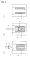
- Fig. 1 is an explanatory view for explaining a hot expanding piercing step performed as preliminary working of the billet for pipe making.
- Fig. 1(a) shows a state in which the hollow billet is put in place in a container.
- Fig. 1(b) shows a process in which the hollow billet is being expansion-pierced.
- Fig. 1(c) shows the hollow billet after expansion-piercing.
- a hollow billet 1 with a guide hole 1a drilled therein is inserted into a container 2 in such a manner that the bottom part of billet is in contact with the inner surface of the back end of the container 2.
- the hollow billet 1 is heated to about 1100 to 1200°C before being inserted into the container 2.
- the hollow billet 1 is expansion-pierced and the inside diameter thereof is expanded by using a mandrel 4 provided with a plug 3, which is used for expansion and has a predetermined diameter, at the front end thereof.
- the hollow billet 1 having been expansion-pierced (this hollow billet 1 is used as a billet 1 for pipe making) is pushed upward by an ejector from the bottom and is taken out of the container 2.
- the billet 1 for pipe making is reheated and fed to the extrusion press used in the Ugine-Sejournet pipe-making process.
- Such a hard-to-work material may include: a high alloy of high Cr and high Ni, where containing alloying elements in large amounts; an alloy steel containing Ti; and the like.
- Non Patent Literature 1 describes a method in which glass is used as a lubricant in the Ugine-Sejournet pipe-making process. For example, glass powder and/or a lump-like glass powder is supplied, as a lubricant, to the beveled part on the billet upper end and the inner hole (guide hole) of the billet.
- Patent Literatures 1, 2 and 3 describe a method in which a glass lubricant is coated onto the outer surface and the inner surface of the billet in the hot expanding piercing of the hollow billet used in the Ugine-Sejournet pipe-making process.
- high-alloy Hastelloy C276 is processed in Patent Literature 1
- a high-nickel alloy is processed in Patent Literature 2
- a SUS304 material is processed in Patent Literature 3.
- Fig. 1(b) of Patent Literature 1 shows a ball-shaped glass lubricant. This ball-shaped glass lubricant is placed in the beveled part on the upper end of the hollow billet.
- Fig. 4(a) of Patent Literature 1 shows a glass lubricant (formed glass) formed into a ring shape. This ring-shaped glass lubricant is placed on the upper end of the hollow billet 1.
- the formed glass is the one formed by solidifying glass powder with a binder such as silicate soda [0014]
- a binder such as silicate soda
- the ring-shaped formed glass is merely placed on the billet, the glass is dislocated or scattered by vibrations etc during expansion-piercing, and/or by the change of position of the plug. Therefore, the lubrication may become insufficient, and eccentric wall happens to occur in the billet after expansion-piercing.
- a metallic ring has been mounted around the ring-shaped formed glass on the billet upper end (refer to Fig. 2(b) , described later).
- the glass can be prevented from dislocation (misfit) or scattering.
- Non Patent Literature 1 Edited by The Iron and Steel Institute of Japan, "Iron and Steel Handbook, Third edition, Vol. 3, Bar Steel, Steel Pipe, and Rolling Equipment", pp. 1020 - 1021, published by Maruzen Co., Ltd., Jan. 20, 1982
- An objective of the present invention is to provide an upper-end formed glass complex for hot expanding piercing capable of meeting the following requirements (1) and (2) when a hollow billet is subjected to hot expanding piercing.
- the gist of the present invention is as follows:
- An upper-end formed glass complex for hot expanding piercing which is used as an upper-end lubricant for a hollow billet when the hollow billet inserted in a container is subjected to hot expanding piercing using a plug
- the formed glass complex comprises a ring-shaped formed glass part and a ring-shaped projecting part;
- the ring-shaped formed glass part assumes a disc shape having a circular opening for allowing a plug to be inserted at the center thereof;
- the ring-shaped projecting part is attached to the opening of the ring-shaped formed glass part, and assumes a ring shape projecting perpendicularly to the ring-shaped formed glass part.
- the formed glass complex of the present invention preferably has a shape described below. This embodiment is referred to as a "first embodiment".
- the thickness of the ring of the ring-shaped projecting part is 5 to 20 mm
- the outside diameter of the ring-shaped projecting part is 1 to 10 mm smaller than the inside diameter of the hollow billet
- the projection length in a height-wise direction of the ring-shaped projecting part is 5 to 20 mm
- the height of the ring-shaped formed glass part from the billet upper end is 10 to 35 mm.
- the formed glass complex of the present invention preferably has the above-described shape and further meets the conditions described below.
- This embodiment is referred to as a "second embodiment".
- the upper side of the opening of the ring-shaped formed glass part is beveled; and the bevel angle is 10 to 20° relative to the vertical line.
- a billet for hot extrusion pipe making of the present invention when the hollow billet is subjected to hot expanding piercing, the worker's safety can be ensured. Also, a billet for pipe making having a very small number of inner surface defects (scratch flaws, seizure flaws, etc.) can be manufactured.
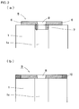
- Fig. 2 is longitudinal sectional views for schematically showing the shapes of the upper-end formed glass lubricants.
- Fig. 2(a) shows the upper-end formed glass complex of the present invention
- Fig. 2(b) shows a conventional upper-end formed glass.
- an upper-end formed glass complex 5 in accordance with the present invention comprises a ring-shaped formed glass part 6 and a ring-shaped projecting part 7.
- the ring-shaped formed glass part 6 assumes a disc shape having a circular opening 8 for allowing a plug (not shown) to be inserted at the center thereof.
- the ring-shaped projecting part 7 is attached to the opening 8 of the ring-shaped formed glass part 6, and assumes a ring shape projecting perpendicularly to the ring-shaped formed glass part 6.
- Fig. 2(a) shows the state in which the upper-end formed glass 5 complex is placed on the upper end of a hollow billet 1.
- the ring-shaped projecting part 7 is inserted in the hollow portion (a guide hole 1a) of the hollow billet 1.
- a conventional ring-shaped formed glass 9 comprises only a ring-shaped flat plate having the opening 8 at the center thereof.
- a metallic ring 10 is attached to the outer periphery of the formed glass 9. The metallic ring 10 is attached to prevent the glass from being dislocated by vibrations during piercing, the change of position of plug, or the like.
- the upper-end formed glass complex of the present invention has the ring-shaped projecting part, and this projecting part is inserted in the guide hole of the hollow billet.
- the upper-end formed glass complex is restrained by the guide hole of the hollow billet. Therefore, even if the vibrations during piercing, the change of position of plug, or the like occurs, the upper-end formed glass complex can be prevented from dislocation. As a result, the metallic ring becomes unnecessary. Therefore, the worker is freed from operations for mounting and demounting the metallic ring to be performed in a high-temperature environment in which the safety is difficult to be ensured.
- the ring-shaped projecting part When the upper-end formed glass complex of the present invention is placed on the upper end of the hollow billet, the ring-shaped projecting part has only to be inserted into the guide hole. Thereby, the center axis of the upper-end formed glass complex can readily coincide with the center axis of the guide hole of the hollow billet. That is, the ring-shaped projecting part also functions as a guide. As a result, the work for placing the upper-end formed glass complex on the upper surface of the hollow billet can be performed smoothly and safely.
- Fig. 2(a) Another reason why the upper-end formed glass complex of the present invention assumes the shape shown in Fig. 2(a) is to prevent defects (scratch flaw, seizure flaw, etc.) from occurring on the inner surface of a billet for pipe making.
- the ring-shaped projecting part included in the upper-end formed glass complex of the present invention is inserted in the guide hole 1a of the hollow billet 1. Since the hollow billet 1 has been heated, the ring-shaped projecting part 7 becomes sticky (molten state). The molten glass thus produced contributes to the lubrication between the inner wall surface of the guide hole 1a and the plug. Further, as indicated by an arrow mark in Fig. 2(a) , glass is also supplied from the ring-shaped formed glass part 6. Thus, the amount of lubricant (lubrication amount) necessary for the lubrication between the inner wall surface of the guide hole 1a and the plug is secured. As a result, defects are prevented from occurring on the inner surface of the billet for pipe making.
- the formed glass complex of a first embodiment of the present invention meets the conditions (a) to (d) described below. Also, the formed glass complex of a second embodiment of the present invention meets the conditions (a) to (d) described below and further meets the conditions (e) and (f) described below.
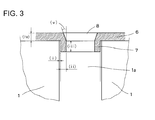
- Fig. 3 is an explanatory view for explaining the formed glass complex of first and second embodiments.
- symbol (i) denotes a gap (distance) between the ring-shaped projecting part 7 and the inner wall of the hollow billet 1.
- symbol (ii) denotes the thickness of the ring of the ring-shaped projecting part 7.
- Symbol (iii) denotes the projection length in a height direction of the ring-shaped projecting part 7.
- Symbol (iv) denotes the height of the ring-shaped formed glass part 6 from the billet upper end (that is, the thickness of the ring-shaped formed glass part 6).
- Symbol (v) denotes the angle of the upper side (beveled part) of the opening of the ring-shaped formed glass part.
- the thickness of the ring of the ring-shaped projecting part (symbol (ii) in Fig. 3 ) to be 5 to 20 mm. If the thickness of the ring is less than 5 mm, the supply amount of lubricant is small, so that the lubricity is impaired. Further, the melting of the ring-shaped projecting part proceeds quickly, so that the formed glass is dislocated (shifted) easily by the vibrations etc during piercing. If the thickness of the ring is more than 20 mm, the supply amount of lubricant is too large, so that the surface properties of the inner surface skin deteriorate. That is, by keeping the thickness of the ring of the ring-shaped projecting part in the above-described range, the lubricity between the hollow billet and the plug is maintained, and thereby the formed glass complex can be effectively prevented from dislocation.
- the outside diameter of the ring-shaped projecting part be smaller than the inside diameter of the hollow billet by 1 to 10 mm.
- the gap between the ring-shaped projecting part 7 and the inner wall of the hollow billet 1 is more than 10 mm, the dislocation occurs easily between the center axis of the hollow billet and the center axis of the upper-end formed glass complex. As a result, uniform lubrication is not provided on the billet inner surface, so that a trouble such as eccentric wall thickness occurs easily.
- the projection length in a height-wise direction of the ring-shaped projecting part symbol (iii) in Fig. 3 ) to be 5 to 20 mm. If the length is less than 5 mm, the supply amount of lubricant is small, so that the lubricity is impaired. In the case where the length is extremely short, the formed glass complex is dislocated (shifted) easily by the vibrations etc during piercing. If the length is more than 20 mm, the supply amount of lubricant is too large, so that the surface properties of the inner surface skin deteriorate. That is, by keeping the length in a height-wise direction of the ring-shaped projecting part in the above-described range, the lubricity between the hollow billet and the plug is maintained, and thereby the formed glass complex can be effectively prevented from dislocation.
- the thickness of the ring-shaped formed glass part (symbol (iv) in Fig. 3 ) to be 10 to 35 mm. If the thickness of the ring-shaped formed glass part is less than 10 mm, the lubricity is easily impaired. This is because the amount of glass supplied from the ring-shaped formed glass part 6 (the arrow mark in Fig. 2(a) shows the flow of glass) decreases. If the thickness is more than 35 mm, the piercing force increases. Also, more lubricant is introduced into the guide hole unnecessarily, so that unit cost of glass increases.
- the bevel angle symbol (v) in Fig. 3 ) on the upper side of the opening of the ring-shaped formed glass part to be 10 to 20°. If the bevel angle deviates from this range, the ring-shaped projecting part is very likely to drop due to the contact of the plug with the ring-shaped formed glass part.
- the outside diameter of the upper-end formed glass complex of the present invention (that is, the outside diameter of the ring-shaped formed glass part) is made larger than the diameter of the plug used for hot piercing. This is because the plug and the workpiece (hollow billet) are prevented from being brought into direct contact with each other.
- a method of manufacturing a billet for hot extrusion pipe making of the present invention is the one in which when the hollow billet is inserted into a container, and hot expanding piercing is downwardly performed by using the plug, the above-described upper-end formed glass complex for hot piercing of the present invention (including the first and second embodiments) is used as an upper-end lubricant for the hollow billet.
- the metallic ring becomes unnecessary as described above. Further, the upper-end formed glass complex can be placed on the upper end of the hollow billet smoothly and safely. As a result, when the hollow billet is subjected to hot expanding piercing, the worker's safety can be ensured.
- the ring-shaped projecting part is placed in a sticky (molten) state as described above, so that a lubricating function is accomplished. Further, glass is also supplied from the ring-shaped formed glass part. As a result, the amount of lubricant (lubrication amount) necessary for lubrication between the inner wall surface of guide hole and the plug is secured, and therefore defects can be prevented from occurring on the inner surface of the billet for pipe making.
- an effect of reducing punched discard metal is also achieved. This is because due to the increase in lubricity between the plug and the metal, the friction coefficient between the material and the tool decreases, and the metal flows to the rear of plug during piercing. As a result of reduction in discard, the material yield increases.
- the method of manufacturing a billet for hot extrusion pipe making of the present invention can be employed in finishing piercing to the size of the billet for hot extrusion pipe making. Also, the manufacturing method of the present invention can be employed not only in finishing piercing but also in preliminary piercing performed at an intermediate stage in the case where the hollow billet is finished into the billet for hot extrusion pipe making by a plurality of piercing operations.
- a billet for hot extrusion pipe making was manufactured by using the upper-end formed glass complex for hot piercing of the present invention as a lubricant and by subjecting a hollow billet to expanding piercing.
- the material grade of the workpiece and other conditions at the piercing operation are as follows:
- the billet was heated to about 1200°C. Thereafter, the billet was inserted into a container, an upper-end lubricant was placed on the upper end of the billet, and subsequently hot piercing (preliminary piercing and finishing piercing) was performed.
- the upper-end formed glass complex of the present invention was used in the finishing piercing. For comparison, the same hot piercing was performed in the case where a conventional ring-shaped formed glass was used as the upper-end lubricant.
- the metallic ring is unnecessary. Thereby, mounting and demounting the metallic ring in a high-temperature environment are not needed, so that the worker's safety is ensured. Also, in the case where the upper-end formed glass complex of the present invention is used, what is required is only to put the upper-end formed glass complex in place on the upper end of billet. Therefore, this work can be replaced easily with automatic supply using a robot or the like.
- the evaluation results of quality are summarized in Table 3.
- Table 3 the dimensions of major portions of the upper-end formed glass complex of the present invention and the conventional ring-shaped formed glass were shown in addition.
- the upper-end formed glass complex of the present invention has an outside diameter of 253 mm and an inside diameter of 105 mm.
- the conventional ring-shaped formed glass has an outside diameter of 205 mm and an inside diameter of 125 mm.
- the "occurrence rate of inner surface defects” is a rate determined by ⁇ (the number of billets on which flaws occurred / the number of billets having been pierced) ⁇ ⁇ 100(%).
- ⁇ Excellent. Indicating that the occurrence rate of billet inner surface flaw (tool seizure, scratch, etc.) is not more than 0.05%.
- ⁇ Good. Indicating that the occurrence rate of billet inner surface flaw is more than 0.05% and not more than 0.60%.
- ⁇ Fair. Indicating that the occurrence rate of billet inner surface flaw is more than 0.60% and not more than 1.00%.
- ⁇ Poor. Indicating that the occurrence rate of billet inner surface flaw is more than 1.00%.
- the occurrence rate of inner surface flaw resulted from seizure caused by poor lubrication was more than 1%.
- the flaw occurrence rate was not more than 1.00%.
- the occurrence of billet inner surface flaw was nil, an excellent result being obtained.
- the occurrence rate of billet inner surface flaw was so low as being not more than 0.60%, ending up in a good result..
- the present invention can be used effectively in manufacturing the billet for hot extrusion pipe making using the formed glass.
Landscapes
- Engineering & Computer Science (AREA)
- Mechanical Engineering (AREA)
- Extrusion Of Metal (AREA)
- Lubricants (AREA)
Abstract
Description
- The present invention relates to an upper-end formed glass complex for hot expanding piercing used as an upper-end lubricant for a hollow billet (especially, a hollow billet made of hard-to-work material), which is used as a starting material in the Ugine-Sejournet pipe-making process, when the hollow billet is subjected to hot expanding piercing. Also, the present invention relates to a method of manufacturing a billet for hot extrusion pipe making, the method using the above-described formed glass complex.
- Unless otherwise stated, the definitions of terms in this description are as follows:
- "Hollow billet": A billet used for hot expanding piercing (hereinafter also referred to simply as "hot piercing"), the billet being fabricated into a hollow shape with a guide hole by machining in advance. Hereinafter, it is also referred to simply as a "billet".
- "Billet for hot extrusion pipe making": A billet used for hot extrusion pipe making, which has been already subjected to hot expanding piercing. Hereinafter, it is also referred to simply as a "billet for pipe making".
- "Upper-end lubricant": A lubricant used at the time of hot expanding piercing of a hollow billet in a state of being placed on the upper end of the hollow billet.
- In the Ugine-Sejournet pipe-making process, glass is used as a lubricant for hot extrusion. This Ugine-Sejournet pipe-making process is excellent in workability in pipe making, and therefore a billet can be processed at a relatively high reduction rate by this pipe-making process. Therefore, the Ugine-Sejournet pipe-making process has been used frequently in manufacturing a seamless pipe made of a hard-to-work material such as a high alloy as the source material.
- A hollow billet is used as a starting material for a hot extruded pipe to be manufactured by the Ugine-Sejournet pipe-making process, and a guide hole is formed in this hollow billet in advance by machining. At the time of hot pipe making, a mandrel of an extrusion press is inserted into this guide hole.
- In the case where a large-diameter mandrel is used to extrude the hollow billet for making a pipe, a pilot hole must be drilled (machined) for the billet according to the mandrel diameter. The processing of the pilot hole significantly decreases the operation efficiency, and also aggravates the yield loss. Usually, in the Ugine-Sejournet pipe-making process, the billet for pipe making to be fed to the extrusion press is subjected to hot expanding piercing as preliminary working.
-
Fig. 1 is an explanatory view for explaining a hot expanding piercing step performed as preliminary working of the billet for pipe making.Fig. 1(a) shows a state in which the hollow billet is put in place in a container.Fig. 1(b) shows a process in which the hollow billet is being expansion-pierced.Fig. 1(c) shows the hollow billet after expansion-piercing. - As shown in
Fig. 1(a) , ahollow billet 1 with aguide hole 1a drilled therein is inserted into acontainer 2 in such a manner that the bottom part of billet is in contact with the inner surface of the back end of thecontainer 2. Thehollow billet 1 is heated to about 1100 to 1200°C before being inserted into thecontainer 2. - Successively, as shown in
Figs. 1(b) and 1(c) , thehollow billet 1 is expansion-pierced and the inside diameter thereof is expanded by using amandrel 4 provided with aplug 3, which is used for expansion and has a predetermined diameter, at the front end thereof. Thehollow billet 1 having been expansion-pierced (thishollow billet 1 is used as abillet 1 for pipe making) is pushed upward by an ejector from the bottom and is taken out of thecontainer 2. Subsequently, thebillet 1 for pipe making is reheated and fed to the extrusion press used in the Ugine-Sejournet pipe-making process. - In the hot expanding piercing step shown in
Fig. 1 , in the case where the hollow billet is made of a hard-to-work material, defects such as tool seizing and scratches caused by poor lubrication are very likely to occur on the outer surface and/or the inner surface of the hot pierced billet. Such a hard-to-work material may include: a high alloy of high Cr and high Ni, where containing alloying elements in large amounts; an alloy steel containing Ti; and the like. - As the prior art for preventing the defect caused by poor lubrication from occurring, the methods described below have been disclosed.
-
Non Patent Literature 1 describes a method in which glass is used as a lubricant in the Ugine-Sejournet pipe-making process. For example, glass powder and/or a lump-like glass powder is supplied, as a lubricant, to the beveled part on the billet upper end and the inner hole (guide hole) of the billet. -
Patent Literatures Patent Literature 1, a high-nickel alloy is processed inPatent Literature 2, and a SUS304 material is processed inPatent Literature 3. - Concerning the specific shape of glass lubricant, for example,
Fig. 1(b) ofPatent Literature 1 shows a ball-shaped glass lubricant. This ball-shaped glass lubricant is placed in the beveled part on the upper end of the hollow billet. Also, Fig. 4(a) ofPatent Literature 1 shows a glass lubricant (formed glass) formed into a ring shape. This ring-shaped glass lubricant is placed on the upper end of thehollow billet 1. The formed glass is the one formed by solidifying glass powder with a binder such as silicate soda [0014]
In the hot piercing of the hard-to-work material, sufficient lubrication cannot be provided by merely coating glass powder or placing the lump-like glass in the beveled part on the upper end of the hollow billet. In particular, the inner surface of the hollow billet cannot be sufficiently lubricated. In some cases, therefore, there is used a method in which the formed glass of a ring shape is placed on the upper end of the hollow billet (example: the formed glass shown in Fig. 4(a) of Patent Literature 1). - However, in the case where the ring-shaped formed glass is merely placed on the billet, the glass is dislocated or scattered by vibrations etc during expansion-piercing, and/or by the change of position of the plug.. Therefore, the lubrication may become insufficient, and eccentric wall happens to occur in the billet after expansion-piercing.
- Conventionally, at the time of hot expanding piercing, a metallic ring has been mounted around the ring-shaped formed glass on the billet upper end (refer to
Fig. 2(b) , described later). By the mounting of this metallic ring, the glass can be prevented from dislocation (misfit) or scattering. - However, the method in which the metallic ring is mounted around the ring-shaped formed glass has the following problems:
- (1) Mounting the metallic ring before hot expanding piercing and demounting it after the completion of expansion-piercing are performed in a high-temperature environment. Therefore, it is difficult to ensure the worker's safety.
- (2) The inner surface of the hollow billet cannot be sufficiently lubricated by merely placing the glass lubricant on the upper end of the hollow billet. Therefore, defects may occur on the inner surface of the billet after hot expanding piercing.
-
- Patent Literature 1: Japanese Patent Application Publication No.
2005-927 - Patent Literature 2: Japanese Patent Application Publication No.
2005-59069 - Patent Literature 3: Japanese Patent Application Publication No.
2007-229771 - Non Patent Literature 1: Edited by The Iron and Steel Institute of Japan, "Iron and Steel Handbook, Third edition, Vol. 3, Bar Steel, Steel Pipe, and Rolling Equipment", pp. 1020 - 1021, published by Maruzen Co., Ltd., Jan. 20, 1982
- An objective of the present invention is to provide an upper-end formed glass complex for hot expanding piercing capable of meeting the following requirements (1) and (2) when a hollow billet is subjected to hot expanding piercing.
- (1) The worker's safety can be ensured.
- (2) Defects (scratch flaw, seizure flaw, etc.) occurring on the inner surface of a billet for pipe making can be prevented.
Another objective of the present invention is to provide a method of manufacturing a billet for hot extrusion pipe making, the method using the formed glass of the present invention. - The gist of the present invention is as follows:
- (I) An upper-end formed glass complex for hot expanding piercing, which is used as an upper-end lubricant for a hollow billet when the hollow billet inserted in a container is subjected to hot expanding piercing using a plug, wherein
the formed glass complex comprises a ring-shaped formed glass part and a ring-shaped projecting part;
the ring-shaped formed glass part assumes a disc shape having a circular opening for allowing a plug to be inserted at the center thereof; and
the ring-shaped projecting part is attached to the opening of the ring-shaped formed glass part, and assumes a ring shape projecting perpendicularly to the ring-shaped formed glass part. - The formed glass complex of the present invention preferably has a shape described below. This embodiment is referred to as a "first embodiment".
In the upper-end formed glass complex for hot expanding piercing described in the above-described item (I),
the thickness of the ring of the ring-shaped projecting part is 5 to 20 mm,
the outside diameter of the ring-shaped projecting part is 1 to 10 mm smaller than the inside diameter of the hollow billet,
the projection length in a height-wise direction of the ring-shaped projecting part is 5 to 20 mm, and
the height of the ring-shaped formed glass part from the billet upper end is 10 to 35 mm. - The formed glass complex of the present invention preferably has the above-described shape and further meets the conditions described below. This embodiment is referred to as a "second embodiment".
The upper side of the opening of the ring-shaped formed glass part is beveled; and
the bevel angle is 10 to 20° relative to the vertical line. - (II) A method of manufacturing a billet for hot extrusion pipe making, wherein
when a hollow billet is inserted into a container, and hot expanding piercing is downwardly performed by using a plug, the above-described upper-end formed glass complex for hot piercing of the present invention (including the first and second embodiments) is used as an upper-end lubricant for the hollow billet. - The upper-end formed glass complex for hot piercing of the present invention achieves the following remarkable effects:
- (1) When the hollow billet is subjected to hot expanding piercing, the worker's safety can be ensured.
- (2)Defects (scratch flaw, seizure flaw, etc.) can be prevented from occurring on the inner surface of a billet for pipe making.
- According to the method of manufacturing a billet for hot extrusion pipe making of the present invention, when the hollow billet is subjected to hot expanding piercing, the worker's safety can be ensured. Also, a billet for pipe making having a very small number of inner surface defects (scratch flaws, seizure flaws, etc.) can be manufactured.
-
- [
Fig. 1] Fig. 1 is explanatory views for explaining a processing step of hot expanding piercing performed as preliminary working of a billet for pipe making,Fig. 1(a) showing a state in which a hollow billet is inserted in a container,Fig. 1(b) showing a process in which the hollow billet is being pierced, andFig. 1(c) showing the hollow billet having been pierced. - [
Fig. 2] Fig. 2 is longitudinal sectional views for schematically showing the shapes of upper-end formed glass lubricants,Fig. 2(a) showing the upper-end formed glass complex of the present invention, andFig. 2(b) showing a conventional upper-end formed glass. - [
Fig. 3] Fig. 3 is an explanatory view for explaining formed glass complex of first and second embodiments of the present invention. - An upper-end formed glass complex for hot piercing in accordance with the present invention will now be described with reference to the accompanying drawings.
-
Fig. 2 is longitudinal sectional views for schematically showing the shapes of the upper-end formed glass lubricants.Fig. 2(a) shows the upper-end formed glass complex of the present invention, andFig. 2(b) shows a conventional upper-end formed glass. - As shown in
Fig. 2(a) , an upper-end formedglass complex 5 in accordance with the present invention comprises a ring-shaped formedglass part 6 and a ring-shaped projectingpart 7. The ring-shaped formedglass part 6 assumes a disc shape having acircular opening 8 for allowing a plug (not shown) to be inserted at the center thereof. The ring-shaped projectingpart 7 is attached to theopening 8 of the ring-shaped formedglass part 6, and assumes a ring shape projecting perpendicularly to the ring-shaped formedglass part 6. -
Fig. 2(a) shows the state in which the upper-end formedglass 5 complex is placed on the upper end of ahollow billet 1. The ring-shaped projectingpart 7 is inserted in the hollow portion (aguide hole 1a) of thehollow billet 1. - As shown in
Fig. 2(b) , a conventional ring-shaped formed glass 9 comprises only a ring-shaped flat plate having theopening 8 at the center thereof. When the conventional ring-shaped formed glass 9 is used, ametallic ring 10 is attached to the outer periphery of the formed glass 9. Themetallic ring 10 is attached to prevent the glass from being dislocated by vibrations during piercing, the change of position of plug, or the like. - One reason why the upper-end formed glass complex of the present invention assumes the shape shown in
Fig. 2(a) is to ensure the worker's safety in hot expanding piercing the hollow billet. - The upper-end formed glass complex of the present invention has the ring-shaped projecting part, and this projecting part is inserted in the guide hole of the hollow billet. In other words, the upper-end formed glass complex is restrained by the guide hole of the hollow billet. Therefore, even if the vibrations during piercing, the change of position of plug, or the like occurs, the upper-end formed glass complex can be prevented from dislocation. As a result, the metallic ring becomes unnecessary. Therefore, the worker is freed from operations for mounting and demounting the metallic ring to be performed in a high-temperature environment in which the safety is difficult to be ensured.
- When the upper-end formed glass complex of the present invention is placed on the upper end of the hollow billet, the ring-shaped projecting part has only to be inserted into the guide hole. Thereby, the center axis of the upper-end formed glass complex can readily coincide with the center axis of the guide hole of the hollow billet. That is, the ring-shaped projecting part also functions as a guide. As a result, the work for placing the upper-end formed glass complex on the upper surface of the hollow billet can be performed smoothly and safely.
- Another reason why the upper-end formed glass complex of the present invention assumes the shape shown in
Fig. 2(a) is to prevent defects (scratch flaw, seizure flaw, etc.) from occurring on the inner surface of a billet for pipe making. - As shown in
Fig. 2(a) , the ring-shaped projecting part included in the upper-end formed glass complex of the present invention is inserted in theguide hole 1a of thehollow billet 1. Since thehollow billet 1 has been heated, the ring-shaped projectingpart 7 becomes sticky (molten state). The molten glass thus produced contributes to the lubrication between the inner wall surface of theguide hole 1a and the plug. Further, as indicated by an arrow mark inFig. 2(a) , glass is also supplied from the ring-shaped formedglass part 6. Thus, the amount of lubricant (lubrication amount) necessary for the lubrication between the inner wall surface of theguide hole 1a and the plug is secured. As a result, defects are prevented from occurring on the inner surface of the billet for pipe making. - The formed glass complex of a first embodiment of the present invention meets the conditions (a) to (d) described below. Also, the formed glass complex of a second embodiment of the present invention meets the conditions (a) to (d) described below and further meets the conditions (e) and (f) described below.
- (a) The ring of the ring-shaped projecting part has a thickness of 5 to 20 mm.
- (b) The outside diameter of the ring-shaped projecting part is smaller than the inside diameter of the hollow billet by 1 to 10 mm.
- (c) The projection length in a height-wise direction of the ring-shaped projecting part is 5 to 20 mm.
- (d) The height of the ring-shaped formed glass part from the billet upper end is 10 to 35 mm.
- (e) The upper side of the opening of the ring-shaped formed glass part is beveled.
- (f) The bevel angle is 10 to 20° relative to the vertical line.
-
Fig. 3 is an explanatory view for explaining the formed glass complex of first and second embodiments. InFig. 3 , symbol (i) denotes a gap (distance) between the ring-shaped projectingpart 7 and the inner wall of thehollow billet 1. Symbol (ii) denotes the thickness of the ring of the ring-shaped projectingpart 7. Symbol (iii) denotes the projection length in a height direction of the ring-shaped projectingpart 7. Symbol (iv) denotes the height of the ring-shaped formedglass part 6 from the billet upper end (that is, the thickness of the ring-shaped formed glass part 6). Symbol (v) denotes the angle of the upper side (beveled part) of the opening of the ring-shaped formed glass part. - The reasons why the formed glass complex of the first embodiment needs to meet the conditions (a) to (d) are as follows:
- It is desirable to specify the thickness of the ring of the ring-shaped projecting part (symbol (ii) in
Fig. 3 ) to be 5 to 20 mm. If the thickness of the ring is less than 5 mm, the supply amount of lubricant is small, so that the lubricity is impaired. Further, the melting of the ring-shaped projecting part proceeds quickly, so that the formed glass is dislocated (shifted) easily by the vibrations etc during piercing. If the thickness of the ring is more than 20 mm, the supply amount of lubricant is too large, so that the surface properties of the inner surface skin deteriorate. That is, by keeping the thickness of the ring of the ring-shaped projecting part in the above-described range, the lubricity between the hollow billet and the plug is maintained, and thereby the formed glass complex can be effectively prevented from dislocation. - It is desirable that the outside diameter of the ring-shaped projecting part be smaller than the inside diameter of the hollow billet by 1 to 10 mm. In other words, it is desirable to specify the difference between the outside diameter of the ring-shaped projecting part and the inside diameter of the hollow billet (for example, symbol (i) shown in
Fig. 3 ) to be 1 to 10 mm. If the gap between the ring-shaped projectingpart 7 and the inner wall of thehollow billet 1 is less than 1 mm, it is difficult to insert the ring-shaped projectingpart 7 into theguide hole 1a. If the gap between the ring-shaped projectingpart 7 and the inner wall of thehollow billet 1 is more than 10 mm, the dislocation occurs easily between the center axis of the hollow billet and the center axis of the upper-end formed glass complex. As a result, uniform lubrication is not provided on the billet inner surface, so that a trouble such as eccentric wall thickness occurs easily. - It is desirable to specify the projection length in a height-wise direction of the ring-shaped projecting part (symbol (iii) in
Fig. 3 ) to be 5 to 20 mm. If the length is less than 5 mm, the supply amount of lubricant is small, so that the lubricity is impaired. In the case where the length is extremely short, the formed glass complex is dislocated (shifted) easily by the vibrations etc during piercing. If the length is more than 20 mm, the supply amount of lubricant is too large, so that the surface properties of the inner surface skin deteriorate. That is, by keeping the length in a height-wise direction of the ring-shaped projecting part in the above-described range, the lubricity between the hollow billet and the plug is maintained, and thereby the formed glass complex can be effectively prevented from dislocation. - It is desirable to specify the thickness of the ring-shaped formed glass part (symbol (iv) in
Fig. 3 ) to be 10 to 35 mm. If the thickness of the ring-shaped formed glass part is less than 10 mm, the lubricity is easily impaired. This is because the amount of glass supplied from the ring-shaped formed glass part 6 (the arrow mark inFig. 2(a) shows the flow of glass) decreases. If the thickness is more than 35 mm, the piercing force increases. Also, more lubricant is introduced into the guide hole unnecessarily, so that unit cost of glass increases. - The reasons why the formed glass complex of the second embodiment needs to meet the conditions (e) and (f), other than meeting the conditions (a) to (d), are as follows:
- It is desirable to bevel the upper side of the opening of the ring-shaped formed glass part. This is because the formed glass part is likely broken by the impact at the time when the plug comes into contact with the upper side of the opening of the ring-shaped formed glass part, and accordingly the ring-shaped projecting part may drop.
- It is desirable to specify the bevel angle (symbol (v) in
Fig. 3 ) on the upper side of the opening of the ring-shaped formed glass part to be 10 to 20°. If the bevel angle deviates from this range, the ring-shaped projecting part is very likely to drop due to the contact of the plug with the ring-shaped formed glass part. - While being taken for granted in view of the purpose of lubrication, the outside diameter of the upper-end formed glass complex of the present invention (that is, the outside diameter of the ring-shaped formed glass part) is made larger than the diameter of the plug used for hot piercing. This is because the plug and the workpiece (hollow billet) are prevented from being brought into direct contact with each other.
- If the above-described upper-end formed glass complex for hot piercing of the present invention is used when the hollow billet is subjected to hot expanding piercing, the following remarkable effects are achieved:
- (1) Since the metallic ring is unnecessary, the worker's safety can be ensured.
- (2) Since the amount of lubricant (lubrication amount) necessary for lubrication between the inner wall surface of guide hole and the plug is secured, defects (scratch flaw, seizure flaw, etc.) can be prevented from occurring on the inner surface of the billet for pipe making.
- A method of manufacturing a billet for hot extrusion pipe making of the present invention is the one in which when the hollow billet is inserted into a container, and hot expanding piercing is downwardly performed by using the plug, the above-described upper-end formed glass complex for hot piercing of the present invention (including the first and second embodiments) is used as an upper-end lubricant for the hollow billet.
- By using the upper-end formed glass complex for hot piercing of the present invention (including the first and second embodiments), the metallic ring becomes unnecessary as described above. Further, the upper-end formed glass complex can be placed on the upper end of the hollow billet smoothly and safely. As a result, when the hollow billet is subjected to hot expanding piercing, the worker's safety can be ensured.
- Also, by using the upper-end formed glass complex for hot piercing of the present invention (including the first and second embodiments), the ring-shaped projecting part is placed in a sticky (molten) state as described above, so that a lubricating function is accomplished. Further, glass is also supplied from the ring-shaped formed glass part. As a result, the amount of lubricant (lubrication amount) necessary for lubrication between the inner wall surface of guide hole and the plug is secured, and therefore defects can be prevented from occurring on the inner surface of the billet for pipe making.
- By using the upper-end formed glass complex for hot piercing of the present invention (including the first and second embodiments), an effect of reducing punched discard metal is also achieved. This is because due to the increase in lubricity between the plug and the metal, the friction coefficient between the material and the tool decreases, and the metal flows to the rear of plug during piercing. As a result of reduction in discard, the material yield increases.
- The method of manufacturing a billet for hot extrusion pipe making of the present invention can be employed in finishing piercing to the size of the billet for hot extrusion pipe making. Also, the manufacturing method of the present invention can be employed not only in finishing piercing but also in preliminary piercing performed at an intermediate stage in the case where the hollow billet is finished into the billet for hot extrusion pipe making by a plurality of piercing operations.
- A billet for hot extrusion pipe making was manufactured by using the upper-end formed glass complex for hot piercing of the present invention as a lubricant and by subjecting a hollow billet to expanding piercing. The material grade of the workpiece and other conditions at the piercing operation are as follows:
- Material grade of workpiece (hollow billet): High Cr-Ni alloy (25%Cr-30%Ni)
- Billet size and tool size: Refer to Table 1
- Upper-end lubricant: SiO2-Al2O3-B2O3-CaO based lubricant
- [Table 1]

- After a glass lubricant had been coated onto the outer surface and the inner surface of the billet as the workpiece, the billet was heated to about 1200°C. Thereafter, the billet was inserted into a container, an upper-end lubricant was placed on the upper end of the billet, and subsequently hot piercing (preliminary piercing and finishing piercing) was performed. The upper-end formed glass complex of the present invention was used in the finishing piercing. For comparison, the same hot piercing was performed in the case where a conventional ring-shaped formed glass was used as the upper-end lubricant.
- After piercing, operation conditions, quality (billet inner surface flaw), and discard metal weight were evaluated.
- The evaluation results of operation conditions are given in Table 2.
- [Table 2]

- As shown in Table 2, in the case where the upper-end formed glass complex of the present invention is used, the metallic ring is unnecessary. Thereby, mounting and demounting the metallic ring in a high-temperature environment are not needed, so that the worker's safety is ensured. Also, in the case where the upper-end formed glass complex of the present invention is used, what is required is only to put the upper-end formed glass complex in place on the upper end of billet. Therefore, this work can be replaced easily with automatic supply using a robot or the like.
- The evaluation results of quality (billet inner surface flaw) are summarized in Table 3. In Table 3, the dimensions of major portions of the upper-end formed glass complex of the present invention and the conventional ring-shaped formed glass were shown in addition. The upper-end formed glass complex of the present invention has an outside diameter of 253 mm and an inside diameter of 105 mm. Also, the conventional ring-shaped formed glass has an outside diameter of 205 mm and an inside diameter of 125 mm.
- [Table 3]

- In Table 3, the meanings of symbols in the "evaluation" column are as described below. Herein, the "occurrence rate of inner surface defects" is a rate determined by {(the number of billets on which flaws occurred / the number of billets having been pierced)} × 100(%).
⊚: Excellent. Indicating that the occurrence rate of billet inner surface flaw (tool seizure, scratch, etc.) is not more than 0.05%.
○: Good. Indicating that the occurrence rate of billet inner surface flaw is more than 0.05% and not more than 0.60%.
Δ: Fair. Indicating that the occurrence rate of billet inner surface flaw is more than 0.60% and not more than 1.00%.
× : Poor. Indicating that the occurrence rate of billet inner surface flaw is more than 1.00%. - Also, in Table 3, items (i) to (v) in the "dimension of major portions" column correspond to symbols (i) to (v) shown in
Fig. 3 . - As shown in Table 3, in Conventional Example, the occurrence rate of inner surface flaw resulted from seizure caused by poor lubrication was more than 1%. In Inventive Example of the present invention, however, the flaw occurrence rate was not more than 1.00%. In particular, in Inventive Example of the present invention E (corresponding to the second embodiment), the occurrence of billet inner surface flaw was nil, an excellent result being obtained. Also, in Inventive Examples of the present invention C and D (corresponding to the first embodiment), the occurrence rate of billet inner surface flaw was so low as being not more than 0.60%, ending up in a good result..
- The evaluation results of discard metal weight are given in Table 4.
- [Table 4]

- As shown in Table 4, in the piercing using the formed glass complex of Inventive Example of the present invention E, due to the increase in lubricity between the plug and the metal, the metal flowed to the rear of plug during piercing, and the discard metal decreased significantly as compared with Conventional Example.
- The present invention can be used effectively in manufacturing the billet for hot extrusion pipe making using the formed glass.
- 1: hollow billet, billet for pipe making, 1a: guide hole, 2: container, 3: plug, 4: mandrel, 5: upper-end formed glass complex, 6: ring-shaped formed glass part, 7: ring-shaped projecting part, 8: opening, 9: conventional ring-shaped formed glass, 10: metallic ring
Claims (4)
- An upper-end formed glass complex for hot expanding piercing, which is used as an upper-end lubricant for a hollow billet when the hollow billet inserted in a container is subjected to hot expanding piercing using a plug, characterized in that
the formed glass complex comprises a ring-shaped formed glass part and a ring-shaped projecting part;
the ring-shaped formed glass part assumes a disc shape having a circular opening for allowing a plug to be inserted at the center thereof; and
the ring-shaped projecting part is attached to the opening of the ring-shaped formed glass part, and assumes a ring shape projecting perpendicularly to the ring-shaped formed glass part. - The upper-end formed glass complex for hot expanding piercing according to claim 1, characterized in that
the thickness of the ring of the ring-shaped projecting part is 5 to 20 mm;
the outside diameter of the ring-shaped projecting part is smaller than the inside diameter of the hollow billet by 1 to 10 mm;
the projection length in a height-wise direction of the ring-shaped projecting part is 5 to 20 mm; and
the height of the ring-shaped formed glass part from the billet upper surface is 10 to 35 mm. - The upper-end formed glass complex for hot expanding piercing according to claim 2, characterized in that
the upper side of the opening of the ring-shaped formed glass part is beveled; and
the bevel angle is 10 to 20° relative to the vertical line. - A method of manufacturing a billet for hot extrusion pipe making, characterized in that
when a hollow billet is inserted into a container, and hot expanding piercing is downwardly performed by using a plug, the upper-end formed glass complex for hot expanding piercing described in any one of claims 1 to 3 is used as an upper-end lubricant for the hollow billet.
Applications Claiming Priority (2)
| Application Number | Priority Date | Filing Date | Title |
|---|---|---|---|
| JP2008306739A JP4518205B2 (en) | 2008-12-01 | 2008-12-01 | Manufacturing method of upper glass forming material for hot drilling and billet for hot extrusion pipe making |
| PCT/JP2009/068459 WO2010064507A1 (en) | 2008-12-01 | 2009-10-28 | Upper-side formed glass for hot boring and process for producing billet for tube formation by hot extrusion |
Publications (3)
| Publication Number | Publication Date |
|---|---|
| EP2374550A1 true EP2374550A1 (en) | 2011-10-12 |
| EP2374550A4 EP2374550A4 (en) | 2016-01-13 |
| EP2374550B1 EP2374550B1 (en) | 2017-01-18 |
Family
ID=42233161
Family Applications (1)
| Application Number | Title | Priority Date | Filing Date |
|---|---|---|---|
| EP09830275.5A Not-in-force EP2374550B1 (en) | 2008-12-01 | 2009-10-28 | Upper-side formed glass for hot boring and process for producing billet for tube formation by hot extrusion |
Country Status (6)
| Country | Link |
|---|---|
| US (1) | US8327676B2 (en) |
| EP (1) | EP2374550B1 (en) |
| JP (1) | JP4518205B2 (en) |
| CN (1) | CN102227270A (en) |
| ES (1) | ES2622569T3 (en) |
| WO (1) | WO2010064507A1 (en) |
Families Citing this family (9)
| Publication number | Priority date | Publication date | Assignee | Title |
|---|---|---|---|---|
| JP5282728B2 (en) * | 2009-12-11 | 2013-09-04 | 新日鐵住金株式会社 | Lubricating glass molding material and method for producing hot-extrusion pipe making billet |
| WO2011077650A1 (en) * | 2009-12-21 | 2011-06-30 | 住友金属工業株式会社 | Base tube for cold-drawing, manufacturing method for same, and manufacturing method for cold-drawn tube |
| US9267184B2 (en) | 2010-02-05 | 2016-02-23 | Ati Properties, Inc. | Systems and methods for processing alloy ingots |
| US10207312B2 (en) | 2010-06-14 | 2019-02-19 | Ati Properties Llc | Lubrication processes for enhanced forgeability |
| JP5459347B2 (en) * | 2012-04-18 | 2014-04-02 | 新日鐵住金株式会社 | Round billet for seamless metal pipe and method for producing seamless metal pipe |
| JP5998614B2 (en) * | 2012-04-25 | 2016-09-28 | 新日鐵住金株式会社 | Billet lubricant for hot-spreading drilling and hot-spreading drilling method using the same |
| CN102658305A (en) * | 2012-05-14 | 2012-09-12 | 上海理工大学 | Device and method for processing powder metallurgy oil-retaining bearing inner hole |
| CN103691761B (en) * | 2013-12-20 | 2016-05-18 | 河北宏润核装备科技股份有限公司 | A kind of method of utilizing extrusion equipment to manufacture Large Diameter Pipeline seamless tubular goods |
| CN111014329B (en) * | 2019-12-13 | 2021-09-28 | 广东华昌集团有限公司 | Gapless extrusion method for aluminum alloy seamless pipe |
Family Cites Families (25)
| Publication number | Priority date | Publication date | Assignee | Title |
|---|---|---|---|---|
| US1675910A (en) * | 1926-02-19 | 1928-07-03 | Andrew L Riker | Tool for drawing tubular bosses |
| US2538917A (en) * | 1941-11-22 | 1951-01-23 | Comptoir Ind Etirage | Extrusion of metals |
| US2346376A (en) * | 1942-08-17 | 1944-04-11 | Gen Motors Corp | Radiator tube end |
| GB603582A (en) * | 1944-01-24 | 1948-06-18 | Comptoir Ind Etirage | Improvements in or relating to hot punching of metals |
| US2791924A (en) * | 1951-08-25 | 1957-05-14 | Babcock & Wilcox Co | Rotary piercing processes |
| US2756494A (en) * | 1951-10-15 | 1956-07-31 | Comptoir Ind Etirage | Hot punching of metals |
| GB832138A (en) * | 1957-09-06 | 1960-04-06 | Comptoir Ind Etirage | Production by extrusion of hollow metallic sections |
| US3335589A (en) * | 1964-10-29 | 1967-08-15 | Cefilac | Hot working of materials |
| FR1443987A (en) * | 1965-04-22 | 1966-07-01 | Cefilac | Hot-spinning process for metals with low strain rate |
| FR1447326A (en) * | 1965-06-15 | 1966-07-29 | Cefilac | Hot-spinning of metals and alloys in slow-moving presses |
| FR2032110A5 (en) * | 1969-02-19 | 1970-11-20 | Cefilac | |
| FR2069879A1 (en) * | 1969-11-26 | 1971-09-10 | Cefilac | |
| US3633396A (en) * | 1969-12-08 | 1972-01-11 | Cefilac | Method and apparatus for improvements in the extrusion of metals and alloys |
| JPS59179214A (en) * | 1983-03-30 | 1984-10-11 | Sumitomo Metal Ind Ltd | Manufacture of pipe by hot extrusion |
| JPH0255615A (en) * | 1988-08-17 | 1990-02-26 | Sumitomo Metal Ind Ltd | Billet for extrusion tube making and extrusion tube making method |
| CN1014426B (en) * | 1990-08-16 | 1991-10-23 | 本溪市玻璃研究所 | Glass lubricant for hot piercing of stainless steel |
| JP2743736B2 (en) * | 1992-09-24 | 1998-04-22 | 住友金属工業株式会社 | Hot extrusion pipe making method |
| JP3097359B2 (en) * | 1992-11-30 | 2000-10-10 | 住友金属工業株式会社 | Hot extrusion pipe making method |
| GB2328390B (en) * | 1997-08-23 | 2001-02-07 | Ford Motor Co | Improved bullet tube expanding apparatus |
| CN2523590Y (en) * | 2002-01-29 | 2002-12-04 | 中国科学院金属研究所 | Concave die for hot pipe extruding set |
| JP4172258B2 (en) * | 2002-11-26 | 2008-10-29 | 住友金属工業株式会社 | Hot extrusion pipe manufacturing method for ferritic stainless steel pipes |
| JP4144438B2 (en) * | 2003-06-10 | 2008-09-03 | 住友金属工業株式会社 | Hot-spreading drilling plug and processing method using the same |
| JP4370853B2 (en) | 2003-08-14 | 2009-11-25 | 住友金属工業株式会社 | Hot drilling method for billets for hot extrusion pipe making |
| CN1224473C (en) * | 2003-10-16 | 2005-10-26 | 上海交通大学 | Micron fine-grained titanium-nickel-copper alloy block constant-diameter corner extrusion preparation method |
| JP4706505B2 (en) | 2006-03-02 | 2011-06-22 | 住友金属工業株式会社 | A manufacturing method of a hot billet hollow billet and a hot extrusion pipe making billet, and a hot extrusion pipe manufacturing method using the hot extrusion pipe making billet. |
-
2008
- 2008-12-01 JP JP2008306739A patent/JP4518205B2/en not_active Expired - Fee Related
-
2009
- 2009-10-28 EP EP09830275.5A patent/EP2374550B1/en not_active Not-in-force
- 2009-10-28 WO PCT/JP2009/068459 patent/WO2010064507A1/en not_active Ceased
- 2009-10-28 CN CN2009801477180A patent/CN102227270A/en active Pending
- 2009-10-28 ES ES09830275.5T patent/ES2622569T3/en active Active
-
2011
- 2011-05-26 US US13/116,272 patent/US8327676B2/en not_active Expired - Fee Related
Non-Patent Citations (1)
| Title |
|---|
| See references of WO2010064507A1 * |
Also Published As
| Publication number | Publication date |
|---|---|
| EP2374550B1 (en) | 2017-01-18 |
| US8327676B2 (en) | 2012-12-11 |
| US20110219837A1 (en) | 2011-09-15 |
| ES2622569T3 (en) | 2017-07-06 |
| JP4518205B2 (en) | 2010-08-04 |
| WO2010064507A1 (en) | 2010-06-10 |
| EP2374550A4 (en) | 2016-01-13 |
| JP2010125519A (en) | 2010-06-10 |
| CN102227270A (en) | 2011-10-26 |
Similar Documents
| Publication | Publication Date | Title |
|---|---|---|
| US8327676B2 (en) | Upper-end formed glass complex for hot expanding piercing and method of manufacturing billet for hot extrusion pipe making | |
| US2956337A (en) | Method of boring metals | |
| JP5282728B2 (en) | Lubricating glass molding material and method for producing hot-extrusion pipe making billet | |
| CA2782192C (en) | Blank tube for cold drawing and method for producing the same, and method for producing cold drawn tube | |
| JP4144438B2 (en) | Hot-spreading drilling plug and processing method using the same | |
| JP2009220146A (en) | Drawing die and method of drawing plated steel wire | |
| JP6760027B2 (en) | Manufacturing method of seamless metal tube | |
| JP2003039132A (en) | Die for forging, forging method, forgings, and forging production system | |
| CN112547822A (en) | Inner core formed by drawing aluminum alloy pipe | |
| EP2060334A1 (en) | METHOD OF USING Cr-PLATED MANDREL BAR FOR HOT ROLLING | |
| JP4370853B2 (en) | Hot drilling method for billets for hot extrusion pipe making | |
| JP4706505B2 (en) | A manufacturing method of a hot billet hollow billet and a hot extrusion pipe making billet, and a hot extrusion pipe manufacturing method using the hot extrusion pipe making billet. | |
| RU2799823C1 (en) | Method for manufacturing steel complex-shaped shells | |
| JP5448909B2 (en) | Drawing machine for tubular workpieces | |
| US7257874B2 (en) | Process for manufacturing ring-type metal joints for high pressure ducts | |
| JP2005131667A (en) | Manufacturing method of hot extruded seamless steel pipe | |
| Kramer et al. | IMPROVEMENTS IN CONSOLIDATION AND FABRICATION OF VANADIUM-20 w/o TITANIUM (TV-20) | |
| Saha et al. | Tribology of Extrusion | |
| RU2381855C2 (en) | Moulding method of pipes from titanium, zirconium and its alloys | |
| JPH0847714A (en) | Surface treatment tool for hot working | |
| JP2006175485A (en) | High-efficiency manufacturing method for high dimensional accuracy pipes | |
| Ngaile et al. | Lubrication and Wear in Drawing Operations | |
| Watkins | Cold Forming and Extrusion of steel | |
| JPH05261427A (en) | Hot extrusion pipe making method | |
| Reti et al. | Precious Metal Tubing: Manufacturing Techniques and Applications |
Legal Events
| Date | Code | Title | Description |
|---|---|---|---|
| PUAI | Public reference made under article 153(3) epc to a published international application that has entered the european phase |
Free format text: ORIGINAL CODE: 0009012 |
|
| 17P | Request for examination filed |
Effective date: 20110607 |
|
| AK | Designated contracting states |
Kind code of ref document: A1 Designated state(s): AT BE BG CH CY CZ DE DK EE ES FI FR GB GR HR HU IE IS IT LI LT LU LV MC MK MT NL NO PL PT RO SE SI SK SM TR |
|
| DAX | Request for extension of the european patent (deleted) | ||
| RAP1 | Party data changed (applicant data changed or rights of an application transferred) |
Owner name: NIPPON STEEL & SUMITOMO METAL CORPORATION |
|
| RA4 | Supplementary search report drawn up and despatched (corrected) |
Effective date: 20151211 |
|
| RIC1 | Information provided on ipc code assigned before grant |
Ipc: B21C 23/08 20060101ALI20151207BHEP Ipc: B21J 5/10 20060101ALI20151207BHEP Ipc: B21C 23/00 20060101ALI20151207BHEP Ipc: B21J 3/00 20060101ALI20151207BHEP Ipc: B21C 23/32 20060101AFI20151207BHEP |
|
| GRAP | Despatch of communication of intention to grant a patent |
Free format text: ORIGINAL CODE: EPIDOSNIGR1 |
|
| RIC1 | Information provided on ipc code assigned before grant |
Ipc: B21C 23/00 20060101ALI20160822BHEP Ipc: B21C 23/08 20060101ALI20160822BHEP Ipc: B21J 3/00 20060101ALI20160822BHEP Ipc: B21J 5/10 20060101ALI20160822BHEP Ipc: B21C 23/32 20060101AFI20160822BHEP |
|
| INTG | Intention to grant announced |
Effective date: 20160923 |
|
| GRAS | Grant fee paid |
Free format text: ORIGINAL CODE: EPIDOSNIGR3 |
|
| GRAA | (expected) grant |
Free format text: ORIGINAL CODE: 0009210 |
|
| AK | Designated contracting states |
Kind code of ref document: B1 Designated state(s): AT BE BG CH CY CZ DE DK EE ES FI FR GB GR HR HU IE IS IT LI LT LU LV MC MK MT NL NO PL PT RO SE SI SK SM TR |
|
| REG | Reference to a national code |
Ref country code: GB Ref legal event code: FG4D |
|
| REG | Reference to a national code |
Ref country code: CH Ref legal event code: EP |
|
| REG | Reference to a national code |
Ref country code: AT Ref legal event code: REF Ref document number: 862596 Country of ref document: AT Kind code of ref document: T Effective date: 20170215 |
|
| REG | Reference to a national code |
Ref country code: IE Ref legal event code: FG4D |
|
| REG | Reference to a national code |
Ref country code: DE Ref legal event code: R096 Ref document number: 602009043899 Country of ref document: DE |
|
| REG | Reference to a national code |
Ref country code: SE Ref legal event code: TRGR |
|
| REG | Reference to a national code |
Ref country code: NL Ref legal event code: MP Effective date: 20170118 |
|
| REG | Reference to a national code |
Ref country code: LT Ref legal event code: MG4D |
|
| REG | Reference to a national code |
Ref country code: AT Ref legal event code: MK05 Ref document number: 862596 Country of ref document: AT Kind code of ref document: T Effective date: 20170118 |
|
| PG25 | Lapsed in a contracting state [announced via postgrant information from national office to epo] |
Ref country code: NL Free format text: LAPSE BECAUSE OF FAILURE TO SUBMIT A TRANSLATION OF THE DESCRIPTION OR TO PAY THE FEE WITHIN THE PRESCRIBED TIME-LIMIT Effective date: 20170118 |
|
| REG | Reference to a national code |
Ref country code: ES Ref legal event code: FG2A Ref document number: 2622569 Country of ref document: ES Kind code of ref document: T3 Effective date: 20170706 |
|
| PG25 | Lapsed in a contracting state [announced via postgrant information from national office to epo] |
Ref country code: HR Free format text: LAPSE BECAUSE OF FAILURE TO SUBMIT A TRANSLATION OF THE DESCRIPTION OR TO PAY THE FEE WITHIN THE PRESCRIBED TIME-LIMIT Effective date: 20170118 Ref country code: LT Free format text: LAPSE BECAUSE OF FAILURE TO SUBMIT A TRANSLATION OF THE DESCRIPTION OR TO PAY THE FEE WITHIN THE PRESCRIBED TIME-LIMIT Effective date: 20170118 Ref country code: NO Free format text: LAPSE BECAUSE OF FAILURE TO SUBMIT A TRANSLATION OF THE DESCRIPTION OR TO PAY THE FEE WITHIN THE PRESCRIBED TIME-LIMIT Effective date: 20170418 Ref country code: FI Free format text: LAPSE BECAUSE OF FAILURE TO SUBMIT A TRANSLATION OF THE DESCRIPTION OR TO PAY THE FEE WITHIN THE PRESCRIBED TIME-LIMIT Effective date: 20170118 Ref country code: IS Free format text: LAPSE BECAUSE OF FAILURE TO SUBMIT A TRANSLATION OF THE DESCRIPTION OR TO PAY THE FEE WITHIN THE PRESCRIBED TIME-LIMIT Effective date: 20170518 Ref country code: GR Free format text: LAPSE BECAUSE OF FAILURE TO SUBMIT A TRANSLATION OF THE DESCRIPTION OR TO PAY THE FEE WITHIN THE PRESCRIBED TIME-LIMIT Effective date: 20170419 |
|
| PG25 | Lapsed in a contracting state [announced via postgrant information from national office to epo] |
Ref country code: AT Free format text: LAPSE BECAUSE OF FAILURE TO SUBMIT A TRANSLATION OF THE DESCRIPTION OR TO PAY THE FEE WITHIN THE PRESCRIBED TIME-LIMIT Effective date: 20170118 Ref country code: PL Free format text: LAPSE BECAUSE OF FAILURE TO SUBMIT A TRANSLATION OF THE DESCRIPTION OR TO PAY THE FEE WITHIN THE PRESCRIBED TIME-LIMIT Effective date: 20170118 Ref country code: BG Free format text: LAPSE BECAUSE OF FAILURE TO SUBMIT A TRANSLATION OF THE DESCRIPTION OR TO PAY THE FEE WITHIN THE PRESCRIBED TIME-LIMIT Effective date: 20170418 Ref country code: LV Free format text: LAPSE BECAUSE OF FAILURE TO SUBMIT A TRANSLATION OF THE DESCRIPTION OR TO PAY THE FEE WITHIN THE PRESCRIBED TIME-LIMIT Effective date: 20170118 Ref country code: PT Free format text: LAPSE BECAUSE OF FAILURE TO SUBMIT A TRANSLATION OF THE DESCRIPTION OR TO PAY THE FEE WITHIN THE PRESCRIBED TIME-LIMIT Effective date: 20170518 |
|
| REG | Reference to a national code |
Ref country code: FR Ref legal event code: PLFP Year of fee payment: 9 |
|
| REG | Reference to a national code |
Ref country code: DE Ref legal event code: R097 Ref document number: 602009043899 Country of ref document: DE |
|
| PG25 | Lapsed in a contracting state [announced via postgrant information from national office to epo] |
Ref country code: EE Free format text: LAPSE BECAUSE OF FAILURE TO SUBMIT A TRANSLATION OF THE DESCRIPTION OR TO PAY THE FEE WITHIN THE PRESCRIBED TIME-LIMIT Effective date: 20170118 Ref country code: RO Free format text: LAPSE BECAUSE OF FAILURE TO SUBMIT A TRANSLATION OF THE DESCRIPTION OR TO PAY THE FEE WITHIN THE PRESCRIBED TIME-LIMIT Effective date: 20170118 Ref country code: CZ Free format text: LAPSE BECAUSE OF FAILURE TO SUBMIT A TRANSLATION OF THE DESCRIPTION OR TO PAY THE FEE WITHIN THE PRESCRIBED TIME-LIMIT Effective date: 20170118 Ref country code: SK Free format text: LAPSE BECAUSE OF FAILURE TO SUBMIT A TRANSLATION OF THE DESCRIPTION OR TO PAY THE FEE WITHIN THE PRESCRIBED TIME-LIMIT Effective date: 20170118 |
|
| PLBE | No opposition filed within time limit |
Free format text: ORIGINAL CODE: 0009261 |
|
| STAA | Information on the status of an ep patent application or granted ep patent |
Free format text: STATUS: NO OPPOSITION FILED WITHIN TIME LIMIT |
|
| PG25 | Lapsed in a contracting state [announced via postgrant information from national office to epo] |
Ref country code: DK Free format text: LAPSE BECAUSE OF FAILURE TO SUBMIT A TRANSLATION OF THE DESCRIPTION OR TO PAY THE FEE WITHIN THE PRESCRIBED TIME-LIMIT Effective date: 20170118 Ref country code: SM Free format text: LAPSE BECAUSE OF FAILURE TO SUBMIT A TRANSLATION OF THE DESCRIPTION OR TO PAY THE FEE WITHIN THE PRESCRIBED TIME-LIMIT Effective date: 20170118 |
|
| 26N | No opposition filed |
Effective date: 20171019 |
|
| PG25 | Lapsed in a contracting state [announced via postgrant information from national office to epo] |
Ref country code: SI Free format text: LAPSE BECAUSE OF FAILURE TO SUBMIT A TRANSLATION OF THE DESCRIPTION OR TO PAY THE FEE WITHIN THE PRESCRIBED TIME-LIMIT Effective date: 20170118 |
|
| PG25 | Lapsed in a contracting state [announced via postgrant information from national office to epo] |
Ref country code: MC Free format text: LAPSE BECAUSE OF FAILURE TO SUBMIT A TRANSLATION OF THE DESCRIPTION OR TO PAY THE FEE WITHIN THE PRESCRIBED TIME-LIMIT Effective date: 20170118 |
|
| REG | Reference to a national code |
Ref country code: CH Ref legal event code: PL |
|
| GBPC | Gb: european patent ceased through non-payment of renewal fee |
Effective date: 20171028 |
|
| REG | Reference to a national code |
Ref country code: IE Ref legal event code: MM4A |
|
| PG25 | Lapsed in a contracting state [announced via postgrant information from national office to epo] |
Ref country code: GB Free format text: LAPSE BECAUSE OF NON-PAYMENT OF DUE FEES Effective date: 20171028 Ref country code: CH Free format text: LAPSE BECAUSE OF NON-PAYMENT OF DUE FEES Effective date: 20171031 Ref country code: LI Free format text: LAPSE BECAUSE OF NON-PAYMENT OF DUE FEES Effective date: 20171031 Ref country code: LU Free format text: LAPSE BECAUSE OF NON-PAYMENT OF DUE FEES Effective date: 20171028 |
|
| REG | Reference to a national code |
Ref country code: BE Ref legal event code: MM Effective date: 20171031 |
|
| PG25 | Lapsed in a contracting state [announced via postgrant information from national office to epo] |
Ref country code: BE Free format text: LAPSE BECAUSE OF NON-PAYMENT OF DUE FEES Effective date: 20171031 |
|
| REG | Reference to a national code |
Ref country code: FR Ref legal event code: PLFP Year of fee payment: 10 |
|
| PG25 | Lapsed in a contracting state [announced via postgrant information from national office to epo] |
Ref country code: MT Free format text: LAPSE BECAUSE OF NON-PAYMENT OF DUE FEES Effective date: 20171028 |
|
| PG25 | Lapsed in a contracting state [announced via postgrant information from national office to epo] |
Ref country code: IE Free format text: LAPSE BECAUSE OF NON-PAYMENT OF DUE FEES Effective date: 20171028 |
|
| PGFP | Annual fee paid to national office [announced via postgrant information from national office to epo] |
Ref country code: FR Payment date: 20180913 Year of fee payment: 10 |
|
| PGFP | Annual fee paid to national office [announced via postgrant information from national office to epo] |
Ref country code: SE Payment date: 20181011 Year of fee payment: 10 Ref country code: DE Payment date: 20181016 Year of fee payment: 10 |
|
| PGFP | Annual fee paid to national office [announced via postgrant information from national office to epo] |
Ref country code: ES Payment date: 20181105 Year of fee payment: 10 Ref country code: IT Payment date: 20181018 Year of fee payment: 10 |
|
| REG | Reference to a national code |
Ref country code: DE Ref legal event code: R082 Ref document number: 602009043899 Country of ref document: DE Representative=s name: ZIMMERMANN & PARTNER PATENTANWAELTE MBB, DE Ref country code: DE Ref legal event code: R081 Ref document number: 602009043899 Country of ref document: DE Owner name: NIPPON STEEL CORPORATION, JP Free format text: FORMER OWNER: NIPPON STEEL & SUMITOMO METAL CORP., TOKYO, JP |
|
| PG25 | Lapsed in a contracting state [announced via postgrant information from national office to epo] |
Ref country code: HU Free format text: LAPSE BECAUSE OF FAILURE TO SUBMIT A TRANSLATION OF THE DESCRIPTION OR TO PAY THE FEE WITHIN THE PRESCRIBED TIME-LIMIT; INVALID AB INITIO Effective date: 20091028 |
|
| PG25 | Lapsed in a contracting state [announced via postgrant information from national office to epo] |
Ref country code: CY Free format text: LAPSE BECAUSE OF NON-PAYMENT OF DUE FEES Effective date: 20170118 |
|
| PG25 | Lapsed in a contracting state [announced via postgrant information from national office to epo] |
Ref country code: MK Free format text: LAPSE BECAUSE OF FAILURE TO SUBMIT A TRANSLATION OF THE DESCRIPTION OR TO PAY THE FEE WITHIN THE PRESCRIBED TIME-LIMIT Effective date: 20170118 |
|
| PG25 | Lapsed in a contracting state [announced via postgrant information from national office to epo] |
Ref country code: TR Free format text: LAPSE BECAUSE OF FAILURE TO SUBMIT A TRANSLATION OF THE DESCRIPTION OR TO PAY THE FEE WITHIN THE PRESCRIBED TIME-LIMIT Effective date: 20170118 |
|
| REG | Reference to a national code |
Ref country code: DE Ref legal event code: R119 Ref document number: 602009043899 Country of ref document: DE |
|
| PG25 | Lapsed in a contracting state [announced via postgrant information from national office to epo] |
Ref country code: DE Free format text: LAPSE BECAUSE OF NON-PAYMENT OF DUE FEES Effective date: 20200501 |
|
| PG25 | Lapsed in a contracting state [announced via postgrant information from national office to epo] |
Ref country code: SE Free format text: LAPSE BECAUSE OF NON-PAYMENT OF DUE FEES Effective date: 20191029 |
|
| PG25 | Lapsed in a contracting state [announced via postgrant information from national office to epo] |
Ref country code: FR Free format text: LAPSE BECAUSE OF NON-PAYMENT OF DUE FEES Effective date: 20191031 Ref country code: IT Free format text: LAPSE BECAUSE OF NON-PAYMENT OF DUE FEES Effective date: 20191028 |
|
| REG | Reference to a national code |
Ref country code: ES Ref legal event code: FD2A Effective date: 20210414 |
|
| PG25 | Lapsed in a contracting state [announced via postgrant information from national office to epo] |
Ref country code: ES Free format text: LAPSE BECAUSE OF NON-PAYMENT OF DUE FEES Effective date: 20191029 |