EP2374495A1 - Ventilation device - Google Patents
Ventilation device Download PDFInfo
- Publication number
- EP2374495A1 EP2374495A1 EP10159449A EP10159449A EP2374495A1 EP 2374495 A1 EP2374495 A1 EP 2374495A1 EP 10159449 A EP10159449 A EP 10159449A EP 10159449 A EP10159449 A EP 10159449A EP 2374495 A1 EP2374495 A1 EP 2374495A1
- Authority
- EP
- European Patent Office
- Prior art keywords
- mixed gas
- mixed
- respiratory
- tank
- gas tank
- Prior art date
- Legal status (The legal status is an assumption and is not a legal conclusion. Google has not performed a legal analysis and makes no representation as to the accuracy of the status listed.)
- Granted
Links
Images
Classifications
-
- A—HUMAN NECESSITIES
- A61—MEDICAL OR VETERINARY SCIENCE; HYGIENE
- A61M—DEVICES FOR INTRODUCING MEDIA INTO, OR ONTO, THE BODY; DEVICES FOR TRANSDUCING BODY MEDIA OR FOR TAKING MEDIA FROM THE BODY; DEVICES FOR PRODUCING OR ENDING SLEEP OR STUPOR
- A61M16/00—Devices for influencing the respiratory system of patients by gas treatment, e.g. mouth-to-mouth respiration; Tracheal tubes
- A61M16/10—Preparation of respiratory gases or vapours
- A61M16/12—Preparation of respiratory gases or vapours by mixing different gases
-
- A—HUMAN NECESSITIES
- A61—MEDICAL OR VETERINARY SCIENCE; HYGIENE
- A61M—DEVICES FOR INTRODUCING MEDIA INTO, OR ONTO, THE BODY; DEVICES FOR TRANSDUCING BODY MEDIA OR FOR TAKING MEDIA FROM THE BODY; DEVICES FOR PRODUCING OR ENDING SLEEP OR STUPOR
- A61M16/00—Devices for influencing the respiratory system of patients by gas treatment, e.g. mouth-to-mouth respiration; Tracheal tubes
- A61M16/10—Preparation of respiratory gases or vapours
- A61M16/104—Preparation of respiratory gases or vapours specially adapted for anaesthetics
-
- B—PERFORMING OPERATIONS; TRANSPORTING
- B01—PHYSICAL OR CHEMICAL PROCESSES OR APPARATUS IN GENERAL
- B01F—MIXING, e.g. DISSOLVING, EMULSIFYING OR DISPERSING
- B01F23/00—Mixing according to the phases to be mixed, e.g. dispersing or emulsifying
- B01F23/10—Mixing gases with gases
- B01F23/19—Mixing systems, i.e. flow charts or diagrams; Arrangements, e.g. comprising controlling means
-
- B—PERFORMING OPERATIONS; TRANSPORTING
- B01—PHYSICAL OR CHEMICAL PROCESSES OR APPARATUS IN GENERAL
- B01F—MIXING, e.g. DISSOLVING, EMULSIFYING OR DISPERSING
- B01F35/00—Accessories for mixers; Auxiliary operations or auxiliary devices; Parts or details of general application
- B01F35/75—Discharge mechanisms
-
- A—HUMAN NECESSITIES
- A61—MEDICAL OR VETERINARY SCIENCE; HYGIENE
- A61M—DEVICES FOR INTRODUCING MEDIA INTO, OR ONTO, THE BODY; DEVICES FOR TRANSDUCING BODY MEDIA OR FOR TAKING MEDIA FROM THE BODY; DEVICES FOR PRODUCING OR ENDING SLEEP OR STUPOR
- A61M16/00—Devices for influencing the respiratory system of patients by gas treatment, e.g. mouth-to-mouth respiration; Tracheal tubes
- A61M16/01—Devices for influencing the respiratory system of patients by gas treatment, e.g. mouth-to-mouth respiration; Tracheal tubes specially adapted for anaesthetising
Definitions
- the present invention relates to a respiratory or anesthetic apparatus according to the preamble of claim 1 and a method for mixing at least two different gases in a respiratory and anesthetic apparatus according to the preamble of claim 10.
- Ventilators are used for artificial respiration of patients and can also be used with an anesthetic agent and anesthetic doses as anesthesia equipment for anesthesia.
- the exhaled expiratory gas exhaled by the patient may be reused as inspiratory gas, i. H. It is a rebreathing system with a breathing air circulation system.
- a gas delivery means is provided which directs the breathing air to the patient during inspiration.
- the gas conveyor is either switched off or is operated only with a very low flow.
- the mixed gas consists for example of oxygen and nitrous oxide.
- the gases to be mixed namely oxygen and nitrous oxide, separated by shut-off valves fed to a mixed gas tank.
- the introduction of the gases to be mixed takes place discontinuously to the effect that only one shut-off valve is opened alternately.
- only mixed oxygen or only nitrous oxide is fed to the mixed gas tank.
- the discharge of the mixed gas from the mixed gas tank takes place continuously in a breathing air duct system, in particular in an inspiratory gas line.
- a gas to be mixed for example oxygen
- the concentration of oxygen in the mixed gas tank increases because only oxygen is introduced into the mixed gas tank. This also applies in an analogous manner, provided that, for example, only nitrous oxide is introduced into the mixed gas tank.
- the discharge of the mixed gas from the mixed gas tank takes place continuously.
- the mixed gas discharged from the mixed gas tank is supplied to a breathing air duct system of a respiratory or anesthetic machine. Due to the discontinuous metering, concentration fluctuations occur in the mixed gas tank and thus also in the mixed gas which is supplied to the respiratory air duct system. However, these concentration variations are not desired because the inspiratory gas supplied to the patient should have the most uniform possible concentration.
- Local concentration fluctuations can also occur within the mixed gas tank, so that additional concentration fluctuations of the mixed gas supplied to the respiratory air line system can also occur due to a non-optimum mixing of the mixed gas in the mixed gas tank.
- the object of the present invention is therefore to provide a respiratory or anesthetic apparatus and a method for mixing at least two different gases in a respiratory and anesthetic equipment, in the concentration fluctuations of a mixed gas introduced into a breathing air system simply and reliably with a low technical effort can be compensated.
- a respiratory or anesthetic machine for artificial respiration of a patient comprising a gas conveyor, at least one gas line for forming a breathing air system, in particular a Atemluft Vietnamesesystems, at least one gas mixing device with a mixed gas tank and at least two inlet openings, each with a shut-off device for the separate supply of at least two different gases to be mixed, in particular oxygen, nitrous oxide, air, carbon dioxide or xenon, in the mixed gas tank and for the subsequent supply of the mixed gas from the mixed gas tank into the breathing air duct system, wherein the mixed gas tank is provided with at least two separate outlet openings for discharging the mixed gas from the mixed gas tank and for subsequent supply to the breathing air duct system. Due to the discharge of the mixed gas from the mixed gas tank from at least two separate outlet openings local concentration fluctuations can be compensated within the mixed gas tank.
- the at least two separate outlet openings in the mixed gas tank at a distance of at least 1 cm, 2 cm, 5 cm, 7 cm or 10 cm.
- a mixed gas line is arranged at each of the at least two outlet openings, so that the mixed gas discharged from the at least two outlet openings flows through at least two mixed gas lines before being introduced into the respiratory air line system.
- the at least two mixed gas lines open into a mixed gas manifold and the mixed gas manifold opens into the breathing air duct system.
- the mixed gas manifold an additional mixing of the gases of the mixed gas can take place.
- the at least two mixed gas lines have a different volume for a pneumatic time delay between the at least two outlet openings and the breathing air duct system and / or the mixed gas manifold.
- concentration variations of the gases to be mixed supplied to the mixed gas tank occur.
- only one gas to be mixed is alternately supplied to the mixed gas tank, so that there are fluctuations in concentration in the mixed gas in the mixed gas tank.
- the pneumatic time delay substantially corresponds to the time difference between the first and second times second time.
- the first gas to be mixed is at a minimum concentration in the mixed gas tank.
- the gas which has been taken from the mixed gas tank during the first time mixed with the mixed gas, which has been taken from the mixed gas tank during the second time.
- mixed gas having a maximum concentration of the second gas to be mixed is mixed with mixed gas having a maximum concentration of the first gas to be mixed.
- the volume of at least one mixed gas line is at least 1.1, 1.5, 2, 3 or 5 times larger than the volume of another mixed gas line.
- the gases to be mixed introduced into the mixed gas tank through the at least two inlet openings, each with a shut-off device, can be discontinuously introduced into the mixed gas tank.
- shut-off valves are controlled to the effect that alternately only one obturator is opened.
- the difference in the volume of at least two mixed gas lines substantially corresponds to a deviation of less than 70%, 50%, 30% or 20% of the volume of the mixed gas, which flows during an opening time of a shut-off valve through the outlet opening, which is arranged on the mixed gas line with the larger volume.
- At least one mixed gas line is arranged at least partially, in particular as a buffer tank, within the mixed gas tank.
- the at least one mixed gas line with the larger volume can thus be made compact because it is thereby integrated into the mixed gas tank as a buffer tank and thus overall the gas mixing device has a compact structure.
- Method according to the invention for mixing at least two different gases in a respiratory or anesthetic device comprising the steps of: introducing at least two gases to be mixed into a mixed gas tank, mixing the at least two gases in the mixed gas tank Discharging the mixed gas from the mixed gas tank, introducing the mixed gas into a breathing air duct system, wherein the mixed gas is discharged from the mixed gas tank separately at at least two different outlet openings.
- the mixed gas discharged from an outlet opening is continuously supplied to the respiratory air duct system with a time difference with respect to the mixed gas discharged from another outlet opening and supplied to the respiratory air duct system.
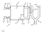
- Fig. 1 is a gas mixing device 1 of an anesthesia machine, not shown mapped.
- the anesthesia machine has a breathing circuit so that expiratory gas exhaled by the patient can be at least partially reused as inspiration gas.
- the anesthesia machine thus serves for artificial respiration and anesthesia of a patient, not shown.
- the inspiratory gas supplied to the patient to be ventilated is supplied to the patient by an inspiratory gas line 16 as part of a respiratory air duct system 14, in particular here as a breathing air circuit system. After flowing through the inspiratory gas line 16 and a Y-piece 18, the inspiration gas is supplied through a mouthpiece 19 to the patient. The exhaled by the patient air as expiratory gas is discharged through an expiratory gas line 17.
- check valves are arranged on the inspiratory gas as well as on the expiratory gas line 16, 17.
- the gas mixing device 1 which provides the mixed gas introduced into the inspiration gas passage 16 through the mixed gas manifold 15, has a mixed gas tank 2 having a first inlet port 7 and a second inlet port 8.
- a first obturator 3 for example a shut-off valve 4 or a gate valve is arranged, and at the second inlet opening 8 is a second obturator 5, for example a second shut-off valve 6 or a second gate valve.
- a first supply line 20 is a first gas to be mixed, for.
- a second gas to be mixed As oxygen, introduced into the mixed gas tank 2 and through a second supply line 21, a second gas to be mixed, for. As nitrous oxide, introduced into the mixed gas tank 2.
- the first obturator 3 and the second obturator 5 are alternately opened, so that flows through the first inlet port 7 at a time only oxygen into the mixed gas tank 2 and at a second period only nitrous oxide is introduced through the second inlet port 8 into the mixed gas tank 2.
- the two shut-off valves 3, 5 are thus not opened simultaneously.
- the mixed gas tank 2 has a first outlet opening 9 and a second outlet opening 10. Through the first and second outlet opening 9, 10, the gas mixed in the mixed gas tank is discharged from the mixed gas tank 2. In this case, the two outlet openings 9, 10 a greater distance, for example in the range of 1 cm to 10 cm on.
- the mixed gas discharged from the first outlet port 9 is supplied to the mixed gas manifold 15 through a first mixed gas line 11, and the mixed gas discharged from the second outlet port 10 is also directed to the mixed gas manifold 15 through a second mixed gas line 12.
- the second mixed gas line 12 is also partially integrated in the mixed gas tank 2 and has a much larger volume than the first mixed gas line 11.
- the second mixed gas line 12 is formed in the mixed gas tank 2 as a buffer tank 13, on which the second outlet opening 10 is present , Because of the separate and separate discharge of the mixed gas from the mixed gas tank through two different outlet openings 9, 10, local concentration fluctuations of oxygen and nitrous oxide within the mixed gas tank 2 can be substantially compensated for in an advantageous manner.
- concentration fluctuations of the two gases oxygen and nitrous oxide occur in the mixed gas. For example, if only oxygen is introduced through the first obturator 3 and the first inlet port 7 into the mixed gas tank 2, the concentration of oxygen in the mixed gas tank 2 increases and thereby also the concentration of nitrous oxide in the mixed gas tank 2 decreases Outlet openings 9, 10 continuously discharged from the mixed gas tank 2 and continuously introduced into the inspiratory gas line 16.
- the volume of the second mixed gas line 12 to the buffer tank 13 is substantially greater than the volume of the first mixed gas line 11. This leads to a pneumatic time delay of the mixed gas, which flows through the first and second mixed gas line 11, 12 in the mixed gas manifold 15.
- the difference in the volume between the first and second mixed gas line 11, 12 is present designed so that the mixed gas passed through the first mixed gas line 11 to the mixed gas manifold 15 has a maximum concentration of oxygen and at the same time the mixed gas introduced through the second mixed gas line 12 into the mixed gas manifold 15 has a maximum concentration of nitrous oxide. Due to the larger volume of the second mixed gas line 12 thus flows the mixed gas, which is discharged through the second mixed gas line 12 from the mixed gas tank 2 and is introduced into the mixed gas manifold 15, with a time delay in the mixed gas manifold 15 with respect to the mixed gas, which through the first mixed gas line 11 is introduced into the mixed gas manifold 15.
- the concentration of oxygen in the mixed gas tank 2 increases and the concentration of nitrous oxide increases, due to the pneumatic delay at the beginning of the mixed gas manifold 15, at an increasing concentration of oxygen of the mixed gas at the end of the first mixed gas line 11 at the mixed gas manifold 15 at the same time the concentration of the mixed gas in the second mixed gas line 12, ie the end of the second mixed gas line 12 at the mixed gas manifold 15, the concentration of nitrous oxide increases.
- the concentration variations of the mixed gas in the mixed gas tank 2 due to the alternating and discontinuous introduction of the two gases to be mixed in the mixed gas tank 2 can be compensated for substantially in a simple manner.
- the separate discharge of the mixed gas from at least two separate outlet openings 9, 10 allows it, to substantially compensate for local concentration fluctuations within the mixed gas tank 2 due to a non-homogeneous mixing of the mixed gas.
- the temporal variations in the concentration of the gases to be mixed in the mixed gas tank 2 due to the discontinuous introduction of these into the mixed gas tank 2 can be substantially compensated by the pneumatic time delay in the two mixed gas lines 11, 12. This allows a substantially constant concentration of the mixed gas supplied to the inspiration gas line 16.
Abstract
Description
Die vorliegende Erfindung betrifft eine Beatmungs- oder Anästhesiegerät gemäß dem Oberbegriff des Anspruches 1 und ein Verfahren zum Mischen von wenigstens zwei verschiedenen Gasen in einem Beatmungs- und Anästhesiegeräte gemäß dem Oberbegriff des Anspruches 10.The present invention relates to a respiratory or anesthetic apparatus according to the preamble of
Für verschiedene medizinische Anwendungen, z. B. bei Operationen, ist eine künstliche Beatmung von Patienten notwendig. Beatmungsgeräte dienen zur künstlichen Beatmung von Patienten und können zusätzlichen mit einem Anästhesiemittelreflektor und Anästhesiemitteldosierer als Anästhesiegeräte auch zur Narkose eingesetzt werden. Bei einigen Beatmungsgeräten kann wenigstens teilweise das von dem Patienten ausgeatmete Exspirationsgas wieder als Inspirationsgas wiederverwendet werden, d. h. es handelt sich um ein Rückatemsystem mit einem Atemluftkreissystem. In dem Beatmungsgerät mit dem Atemluftkreissystem ist eine Gasfördereinrichtung vorhanden, welche die Atemluft während der Inspiration zum Patienten leitet. Während und nach der Ausatmung ist die Gasfördereinrichtung entweder abgeschaltet oder wird nur mit einem sehr geringen Förderstrom betrieben.For various medical applications, eg. As in operations, artificial ventilation of patients is necessary. Ventilators are used for artificial respiration of patients and can also be used with an anesthetic agent and anesthetic doses as anesthesia equipment for anesthesia. In some ventilators, at least in part, the exhaled expiratory gas exhaled by the patient may be reused as inspiratory gas, i. H. It is a rebreathing system with a breathing air circulation system. In the respirator with the breathing circuit a gas delivery means is provided which directs the breathing air to the patient during inspiration. During and after the exhalation, the gas conveyor is either switched off or is operated only with a very low flow.
Insbesondere bei Anästhesiegeräten ist es erforderlich, dem Inspirationsgas ein Mischgas zuzuführen. Das Mischgas besteht dabei beispielsweise aus Sauerstoff und Lachgas. Dabei werden die zu mischenden Gase, nämlich Sauerstoff und Lachgas, getrennt durch Absperrventile einem Mischgastank zugeführt. Das Einleiten der zu mischenden Gase, beispielsweise Sauerstoff oder Lachgas, erfolgt dabei diskontinuierlich dahingehend, dass abwechselnd nur ein Absperrventil geöffnet ist. Es wird somit dem Mischgastank entweder beispielsweise nur Sauerstoff oder nur Lachgas zugeführt. Das Ausleiten des Mischgases aus dem Mischgastank erfolgt dabei kontinuierlich in ein Atemluftleitungssystem, insbesondere in eine Inspirationsgasleitung. Wird ein zu mischendes Gas, beispielsweise Sauerstoff, in den Mischgastank eingeleitet, erhöht sich die Konzentration an Sauerstoff in dem Mischgastank, weil nur Sauerstoff in den Mischgastank eingeleitet wird. Dies gilt auch in analoger Weise, sofern in den Mischgastank beispielsweise nur Lachgas eingeleitet wird. Das Ausleiten des Mischgases aus dem Mischgastank erfolgt dabei kontinuierlich. Das aus dem Mischgastank ausgeleitete Mischgas wird einem Atemluftleitungssystem eines Beatmungs- oder Anästhesiegerätes zugeführt. Auf Grund der diskontinuierlichen Dosierung kommt es in dem Mischgastank und somit auch dem Mischgas, welches dem Atemluftleitungssystem zugeführt wird, zu Konzentrationsschwankungen. Diese Konzentrationsschwankungen sind jedoch nicht gewünscht, weil das dem Patienten zugeführte Inspirationsgas eine möglichst gleichmäßige Konzentration aufweisen soll.Especially in anesthesia equipment, it is necessary to supply a mixed gas to the inspiration gas. The mixed gas consists for example of oxygen and nitrous oxide. The gases to be mixed, namely oxygen and nitrous oxide, separated by shut-off valves fed to a mixed gas tank. The introduction of the gases to be mixed, for example oxygen or nitrous oxide, takes place discontinuously to the effect that only one shut-off valve is opened alternately. Thus, for example, only mixed oxygen or only nitrous oxide is fed to the mixed gas tank. The discharge of the mixed gas from the mixed gas tank takes place continuously in a breathing air duct system, in particular in an inspiratory gas line. If a gas to be mixed, for example oxygen, is introduced into the mixed gas tank, The concentration of oxygen in the mixed gas tank increases because only oxygen is introduced into the mixed gas tank. This also applies in an analogous manner, provided that, for example, only nitrous oxide is introduced into the mixed gas tank. The discharge of the mixed gas from the mixed gas tank takes place continuously. The mixed gas discharged from the mixed gas tank is supplied to a breathing air duct system of a respiratory or anesthetic machine. Due to the discontinuous metering, concentration fluctuations occur in the mixed gas tank and thus also in the mixed gas which is supplied to the respiratory air duct system. However, these concentration variations are not desired because the inspiratory gas supplied to the patient should have the most uniform possible concentration.
Innerhalb des Mischgastanks können auch lokale Konzentrationsschwankungen auftreten, so dass dadurch aufgrund einer nicht optimalen Vermischung des Mischgases in dem Mischgastank ebenfalls zusätzliche Konzentrationsschwankungen des dem Atemluftleitungssystem zugeführten Mischgases auftreten können.Local concentration fluctuations can also occur within the mixed gas tank, so that additional concentration fluctuations of the mixed gas supplied to the respiratory air line system can also occur due to a non-optimum mixing of the mixed gas in the mixed gas tank.
Die Aufgabe der vorliegenden Erfindung besteht deshalb darin, ein Beatmungs- oder Anästhesiegerät und ein Verfahren zum Mischen von wenigstens zwei verschiedenen Gasen in einem Beatmungs- und Anästhesiegeräte zur Verfügung zu stellen, bei dem Konzentrationsschwankungen eines in ein Atemluftleitungssystem eingeleiteten Mischgases einfach und zuverlässig mit einem geringen technischen Aufwand ausgeglichen werden können.The object of the present invention is therefore to provide a respiratory or anesthetic apparatus and a method for mixing at least two different gases in a respiratory and anesthetic equipment, in the concentration fluctuations of a mixed gas introduced into a breathing air system simply and reliably with a low technical effort can be compensated.
Diese Aufgabe wird gelöst mit einem Beatmungs- oder Anästhesiegerät zur künstlichen Beatmung eines Patienten, umfassend eine Gasfördereinrichtung, wenigstens eine Gasleitung zur Ausbildung eines Atemluftleitungssystems, insbesondere eines Atemluftkreissystems, wenigstens eine Gasmischeinrichtung mit einem Mischgastank und wenigstens zwei Einlassöffnungen mit je einem Absperrorgan zur getrennten Zuführung von wenigstens zwei verschiedenen zu mischenden Gasen, insbesondere Sauerstoff, Lachgas, Luft, Kohlendioxid oder Xenon, in den Mischgastank und zur anschließenden Zuführung des Mischgases aus dem Mischgastank in das Atemluftleitungssystem, wobei der Mischgastank mit wenigstens zwei separaten Auslassöffnungen versehen ist zum Ausleiten des Mischgases aus dem Mischgastank und zur anschließenden Zuführung in das Atemluftleitungssystem. Aufgrund des Ausleitens des Mischgases aus dem Mischgastank aus wenigstens zwei separaten Auslassöffnungen können lokale Konzentrationsschwankungen innerhalb des Mischgastankes ausgeglichen werden.This object is achieved with a respiratory or anesthetic machine for artificial respiration of a patient, comprising a gas conveyor, at least one gas line for forming a breathing air system, in particular a Atemluftkreissystems, at least one gas mixing device with a mixed gas tank and at least two inlet openings, each with a shut-off device for the separate supply of at least two different gases to be mixed, in particular oxygen, nitrous oxide, air, carbon dioxide or xenon, in the mixed gas tank and for the subsequent supply of the mixed gas from the mixed gas tank into the breathing air duct system, wherein the mixed gas tank is provided with at least two separate outlet openings for discharging the mixed gas from the mixed gas tank and for subsequent supply to the breathing air duct system. Due to the discharge of the mixed gas from the mixed gas tank from at least two separate outlet openings local concentration fluctuations can be compensated within the mixed gas tank.
In einer ergänzenden Ausgestaltung weisen die wenigstens zwei separaten Auslassöffnungen in dem Mischgastank einen Abstand von wenigstens 1 cm, 2 cm, 5 cm, 7 cm oder 10 cm auf.In a supplementary embodiment, the at least two separate outlet openings in the mixed gas tank at a distance of at least 1 cm, 2 cm, 5 cm, 7 cm or 10 cm.
Insbesondere ist an den wenigstens zwei Auslassöffnungen je eine Mischgasleitung angeordnet, so dass das aus den wenigstens zwei Auslassöffnungen ausgeleitete Mischgas vor dem Einleiten in das Atemluftleitungssystem durch wenigstens zwei Mischgasleitungen strömt.In particular, a mixed gas line is arranged at each of the at least two outlet openings, so that the mixed gas discharged from the at least two outlet openings flows through at least two mixed gas lines before being introduced into the respiratory air line system.
In einer weiteren Ausgestaltung münden die wenigstens zwei Mischgasleitungen in eine Mischgassammelleitung und die Mischgassammelleitung mündet in das Atemluftleitungssystem. In der Mischgassammelleitung kann eine zusätzliche Vermischung der Gase des Mischgases erfolgen.In a further embodiment, the at least two mixed gas lines open into a mixed gas manifold and the mixed gas manifold opens into the breathing air duct system. In the mixed gas manifold, an additional mixing of the gases of the mixed gas can take place.
In einer ergänzenden Ausführungsform weisen die wenigstens zwei Mischgasleitungen ein unterschiedliches Volumen für eine pneumatische Zeitverzögerung zwischen den wenigstens zwei Auslassöffnungen und dem Atemluftleitungssystem und/oder der Mischgassammelleitung auf. Innerhalb des Mischgases in dem Mischgastank treten Konzentrationsschwankungen der dem Mischgastank zugeführten zu mischenden Gase auf. Dabei wird dem Mischgastank abwechselnd jeweils nur ein zu mischendes Gas zugeführt, so dass es zu Konzentrationsschwankungen in dem Mischgas im Mischgastank kommt. Durch eine pneumatische zeitliche Verzögerung des aus den wenigstens zwei Auslassöffnungen entnommenen Mischgases können die Konzentrationsschwankungen der unterschiedlichen dem Mischgastank zugeführten zu mischenden Gase im Wesentlichen ausgeglichen werden. Liegt beispielsweise ein erstes zu mischendes Gas zu einem ersten Zeitpunkt in dem Mischgastank in einer maximalen Konzentration vor und ein zweites zu mischendes Gas in dem Mischgastank zu einem zweiten Zeitpunkt in einer maximalen Konzentration vor, entspricht die pneumatische Zeitverzögerung im Wesentlichen der Zeitdifferenz zwischen dem ersten und zweiten Zeitpunkt. Während des zweiten Zeitpunktes liegt das erste zu mischende Gas in einer minimalen Konzentration in dem Mischgastank vor. Dabei wird beispielsweise das Gas, welches während dem ersten Zeitpunkt dem Mischgastank entnommen worden ist, mit dem Mischgas vermischt, welches während des zweiten Zeitpunktes dem Mischgastank entnommen worden ist. Dadurch wird Mischgas mit einer maximalen Konzentration von dem zweiten zu mischenden Gas mit Mischgas vermischt, welches eine maximale Konzentration von dem ersten zu mischenden Gas aufweist. Aufgrund der kontinuierlich an- und absteigenden Konzentrationsschwankungen des ersten und zweiten zu mischenden Gases in dem Mischgastank können dadurch die auftretenden Konzentrationsschwankungen in dem Mischgastank im Wesentlichen ausgeglichen werden bezüglich des dem Atemluftleitungssystem zugeführten Mischgases.In a supplementary embodiment, the at least two mixed gas lines have a different volume for a pneumatic time delay between the at least two outlet openings and the breathing air duct system and / or the mixed gas manifold. Within the mixed gas in the mixed gas tank, concentration variations of the gases to be mixed supplied to the mixed gas tank occur. In this case, only one gas to be mixed is alternately supplied to the mixed gas tank, so that there are fluctuations in concentration in the mixed gas in the mixed gas tank. By a pneumatic time delay of the extracted from the at least two outlet mixed gas, the concentration fluctuations of the different the mixed gas tank supplied to be mixed gases are substantially offset. For example, if a first gas to be mixed exists at a first time in the mixed gas tank at a maximum concentration and a second gas to be mixed in the mixed gas tank at a second time at a maximum concentration, the pneumatic time delay substantially corresponds to the time difference between the first and second times second time. During the second time, the first gas to be mixed is at a minimum concentration in the mixed gas tank. In this case, for example, the gas which has been taken from the mixed gas tank during the first time, mixed with the mixed gas, which has been taken from the mixed gas tank during the second time. Thereby, mixed gas having a maximum concentration of the second gas to be mixed is mixed with mixed gas having a maximum concentration of the first gas to be mixed. As a result of the continuously increasing and decreasing concentration fluctuations of the first and second gas to be mixed in the mixed gas tank, the concentration fluctuations occurring in the mixed gas tank can be substantially compensated with respect to the mixed gas supplied to the respiratory air line system.
Vorzugsweise ist das Volumen wenigstens einer Mischgasleitung wenigstens um das 1,1-, 1,5-, 2-, 3- oder 5-Fache größer als das Volumen einer anderen Mischgasleitung.Preferably, the volume of at least one mixed gas line is at least 1.1, 1.5, 2, 3 or 5 times larger than the volume of another mixed gas line.
In einer Variante sind die durch die wenigstens zwei Einlassöffnungen mit je einem Absperrorgan in den Mischgastank eingeleiteten zu mischenden Gasen in den Mischgastank diskontinuierlich einleitbar.In a variant, the gases to be mixed introduced into the mixed gas tank through the at least two inlet openings, each with a shut-off device, can be discontinuously introduced into the mixed gas tank.
Zweckmäßig sind die Absperrorgane dahingehend gesteuert, dass abwechselnd nur je ein Absperrorgan geöffnet ist.Advantageously, the shut-off valves are controlled to the effect that alternately only one obturator is opened.
In einer weiteren Ausführungsform entspricht die Differenz des Volumens von wenigstens zwei Mischgasleitungen im Wesentlichen einer Abweichung von weniger als 70 %, 50 %, 30 % oder 20 % dem Volumen des gemischten Gases, das während einer Öffnungszeit eines Absperrorganes durch die Auslassöffnung strömt, welche an der Mischgasleitung mit dem größeren Volumen angeordnet ist.In a further embodiment, the difference in the volume of at least two mixed gas lines substantially corresponds to a deviation of less than 70%, 50%, 30% or 20% of the volume of the mixed gas, which flows during an opening time of a shut-off valve through the outlet opening, which is arranged on the mixed gas line with the larger volume.
Insbesondere ist wenigstens eine Mischgasleitung wenigstens teilweise, insbesondere als Puffertank, innerhalb des Mischgastankes angeordnet. Die wenigstens eine Mischgasleitung mit dem größeren Volumen kann damit kompakt aufgebaut werden, weil diese dadurch in den Mischgastank als Puffertank integriert ist und damit insgesamt die Gasmischeinrichtung einen kompakten Aufbau aufweist.In particular, at least one mixed gas line is arranged at least partially, in particular as a buffer tank, within the mixed gas tank. The at least one mixed gas line with the larger volume can thus be made compact because it is thereby integrated into the mixed gas tank as a buffer tank and thus overall the gas mixing device has a compact structure.
Erfindungsgemäßes Verfahren zum Mischen von wenigstens zwei verschiedenen Gasen in einem Beatmungs- oder Anästhesiegerät, insbesondere eines in dieser Schutzrechtsanmeldung beschriebenen Beatmungs- oder Anästhesiegerätes, mit den Schritten: Einleiten von wenigstens zwei zu mischenden Gasen in einen Mischgastank, Vermischen der wenigstens zwei Gase in dem Mischgastank, Ausleiten des Mischgases aus dem Mischgastank, Einleiten des Mischgases in ein Atemluftleitungssystem, wobei das Mischgas aus dem Mischgastank getrennt an wenigstens zwei verschiedenen Auslassöffnungen ausgeleitet wird.Method according to the invention for mixing at least two different gases in a respiratory or anesthetic device, in particular a respiratory or anesthetic device described in this patent application, comprising the steps of: introducing at least two gases to be mixed into a mixed gas tank, mixing the at least two gases in the mixed gas tank Discharging the mixed gas from the mixed gas tank, introducing the mixed gas into a breathing air duct system, wherein the mixed gas is discharged from the mixed gas tank separately at at least two different outlet openings.
In einer weiteren Ausgestaltung wird das aus einer Auslassöffnung ausgeleitete Mischgas kontinuierlich mit einer Zeitdifferenz dem Atemluftleitungssystem zugeführt bezüglich dem aus einer anderen Auslassöffnung ausgeleiteten und dem Atemluftleitungssystem zugeführten Mischgas.In a further embodiment, the mixed gas discharged from an outlet opening is continuously supplied to the respiratory air duct system with a time difference with respect to the mixed gas discharged from another outlet opening and supplied to the respiratory air duct system.
Es zeigt:
- Fig. 1
- einen vereinfachte Darstellung einer Gasmischeinrichtung.
- Fig. 1
- a simplified representation of a gas mixing device.
In
Das Anästhesiegerät weist ein Atemluftkreissystem auf, so dass von dem Patienten ausgeatmetes Exspirationsgas wenigstens teilweise als Inspirationsgas wiederverwendet werden kann. Das Anästhesiegerät dient somit zur künstlichen Beatmung und zur Narkose eines nicht dargestellten Patienten.The anesthesia machine has a breathing circuit so that expiratory gas exhaled by the patient can be at least partially reused as inspiration gas. The anesthesia machine thus serves for artificial respiration and anesthesia of a patient, not shown.
Das dem zu beatmenden Patienten zugeführte Inspirationsgas wird dem Patienten durch eine Inspirationsgasleitung 16 als Bestandteil eines Atemluftleitungssystems 14, insbesondere hier als Atemluftkreissystem ausgeführt, zugeführt. Nach dem Durchströmen der Inspirationsgasleitung 16 und eines Y-Stückes 18 wird das Inspirationsgas durch ein Mundstück 19 dem Patienten zugeführt. Die von dem Patienten ausgeatmete Luft als Exspirationsgas wird durch eine Exspirationsgasleitung 17 abgeleitet. Dabei sind an der Inspirationsgas- als auch an der Exspirationsgasleitung 16, 17 jeweils nicht dargestellte Rückschlagventile angeordnet.The inspiratory gas supplied to the patient to be ventilated is supplied to the patient by an inspiratory gas line 16 as part of a respiratory air duct system 14, in particular here as a breathing air circuit system. After flowing through the inspiratory gas line 16 and a Y-
In die Inspirationsgasleitung 16 mündet eine Mischgassammelleitung 15. Durch die Mischgasleitung 15 wird Mischgas aus verschiedenen Gasen wie beispielsweise Sauerstoff und Lachgas dem Inspirationsgas für den zu beatmenden Patienten zugeführt. Die Gasmischeinrichtung 1, welche das Mischgas zur Verfügung stellt, welches durch die Mischgassammelleitung 15 in die Inspirationsgasleitung 16 eingeführt wird, weist einen Mischgastank 2 mit einer ersten Einlassöffnung 7 und einer zweiten Einlassöffnung 8 auf. An der ersten Einlassöffnung 7 ist ein erstes Absperrorgan 3, beispielsweise ein Absperrventil 4 oder ein Absperrschieber angeordnet, und an der zweiten Einlassöffnung 8 ist ein zweites Absperrorgan 5, beispielsweise ein zweites Absperrventil 6 oder ein zweiter Absperrschieber. Durch eine erste Zuführleitung 20 wird ein erstes zu mischendes Gas, z. B. Sauerstoff, in den Mischgastank 2 eingeleitet und durch eine zweite Zuführleitung 21 ein zweites zu mischendes Gas, z. B. Lachgas, in den Mischgastank 2 eingeleitet. Dabei wird das erste Absperrorgan 3 und das zweite Absperrorgan 5 abwechselnd geöffnet, so dass durch die erste Einlassöffnung 7 zu einem Zeitabschnitt nur Sauerstoff in den Mischgastank 2 einströmt und zu einem zweiten Zeitabschnitt nur Lachgas durch die zweite Einlassöffnung 8 in den Mischgastank 2 eingeleitet wird. Die beiden Absperrorgane 3, 5 sind somit nicht gleichzeitig geöffnet.Into the inspiratory gas line 16 opens a mixed
Der Mischgastank 2 weist eine erste Auslassöffnung 9 und eine zweite Auslassöffnung 10 auf. Durch die erste und zweite Auslassöffnung 9, 10 wird das in dem Mischgastank gemischte Gas aus dem Mischgastank 2 ausgeleitet. Dabei weisen die beiden Auslassöffnungen 9, 10 einen größeren Abstand, beispielsweise im Bereich von 1 cm bis 10 cm, auf. Das aus der ersten Auslassöffnung 9 ausgeleitete Mischgas wird durch eine erste Mischgasleitung 11 der Mischgassammelleitung 15 zugeführt und das aus der zweiten Auslassöffnung 10 ausgeleitete Mischgas wird durch eine zweite Mischgasleitung 12 ebenfalls zu der Mischgassammelleitung 15 geleitet. Die zweite Mischgasleitung 12 ist dabei auch teilweise in den Mischgastank 2 integriert und weist ein wesentlich größeres Volumen auf als die erste Mischgasleitung 11. Dabei ist die zweite Mischgasleitung 12 in dem Mischgastank 2 als Puffertank 13 ausgebildet, an dem auch die zweite Auslassöffnung 10 vorhanden ist. Aufgrund des getrennten und separaten Ausleitens des Mischgases aus dem Mischgastank durch zwei verschiedene Auslassöffnungen 9, 10 können lokale Konzentrationsschwankungen an Sauerstoff und Lachgas innerhalb des Mischgastankes 2 in vorteilhafter Weise im Wesentlichen ausgeglichen werden.The
Aufgrund der diskontinuierlichen und abwechselnden Einleitung der beiden zu mischenden Gase in den Mischgastank 1 treten Konzentrationsschwankungen der beiden Gase Sauerstoff und Lachgas in dem Mischgas auf. Wird beispielsweise nur Sauerstoff durch das erste Absperrorgan 3 und die erste Einlassöffnung 7 in den Mischgastank 2 eingeleitet, steigt die Konzentration an Sauerstoff in dem Mischgastank 2 an und dadurch sinkt auch die Konzentration an Lachgas in dem Mischgastank 2. Dabei wird das Mischgas aus den beiden Auslassöffnungen 9, 10 kontinuierlich aus dem Mischgastank 2 ausgeleitet und kontinuierlich in die Inspirationsgasleitung 16 eingeleitet. Das Volumen der zweiten Mischgasleitung 12 mit dem Puffertank 13 ist dabei wesentlich größer als das Volumen der ersten Mischgasleitung 11. Dies führt zu einer pneumatischen Zeitverzögerung des Mischgases, welches durch die erste und zweite Mischgasleitung 11, 12 in die Mischgassammelleitung 15 einströmt. Die Differenz des Volumens zwischen der ersten und zweiten Mischgasleitung 11,12 ist dabei dahingehend ausgelegt, dass das durch die erste Mischgasleitung 11 zu der Mischgassammelleitung 15 geleitete Mischgas eine maximale Konzentration an Sauerstoff aufweist und zum gleichen Zeitpunkt das durch die zweite Mischgasleitung 12 in die Mischgassammelleitung 15 eingeleitete Mischgas eine maximale Konzentration an Lachgas aufweist. Aufgrund des größeren Volumens der zweiten Mischgasleitung 12 strömt somit das Mischgas, welches durch die zweite Mischgasleitung 12 aus dem Mischgastank 2 ausgeleitet wird und in die Mischgassammelleitung 15 eingeleitet wird, mit einer zeitlichen Verzögerung in die Mischgassammelleitung 15 bezüglich des Mischgases, welches durch die erste Mischgasleitung 11 in die Mischgassammelleitung 15 eingeleitet wird. Bei einer maximalen Konzentration von Sauerstoff in dem Mischgastank 2 liegt eine minimale Konzentration von Lachgas in dem Mischgastank 2 vor und umgekehrt. Während der ausschließlichen Zuführung von nur Sauerstoff in den Mischgastank 2 steigt kontinuierlich die Konzentration an Sauerstoff in dem Mischgastank 2 an und in analoger Weise sinkt die Konzentration an Lachgas in dem Mischgastank 2. In analoger Weise steigt beim ausschließlichen Einleiten von Lachgas in den Mischgastank 2 kontinuierlich die Konzentration an Lachgas in dem Mischgastank 2 an und die Konzentration an Sauerstoff in dem Mischgastank 2 sinkt ab. Sinkt beispielsweise in dem Mischgastank 2 die Konzentration an Sauerstoff und steigt die Konzentration an Lachgas, führt dies aufgrund der pneumatischen Verzögerung zu Beginn der Mischgassammelleitung 15 dazu, dass bei einer ansteigenden Konzentration an Sauerstoff des Mischgases am Ende der ersten Mischgasleitung 11 an der Mischgassammelleitung 15 gleichzeitig die Konzentration des Mischgases in der zweiten Mischgasleitung 12, d. h. dem Ende der zweiten Mischgasleitung 12 an der Mischgassammelleitung 15, die Konzentration an Lachgas zunimmt. Dies gilt auch umgekehrt. Damit können kontinuierlich die Konzentrationsschwankungen des Mischgases in dem Mischgastank 2 aufgrund der abwechselnden und diskontinuierlichen Einleitung der beiden zu mischenden Gase in dem Mischgastank 2 im Wesentlichen auf einfache Art und Weise ausgeglichen werden.Due to the discontinuous and alternating introduction of the two gases to be mixed into the
Insgesamt betrachtet sind mit dem erfindungsgemäßen Beatmungs- oder Anästhesiegerät wesentliche Vorteile verbunden. Die getrennte Ausleitung des Mischgases aus wenigstens zwei separaten Auslassöffnungen 9, 10 ermöglicht es, lokale Konzentrationsschwankungen innerhalb des Mischgastankes 2 aufgrund einer nicht homogenen Durchmischung des Mischgases im Wesentlichen auszugleichen. Die zeitlichen Schwankungen der Konzentration der zu mischenden Gase in dem Mischgastank 2 aufgrund der diskontinuierlichen Einleitung dieser in den Mischgastank 2 können durch die pneumatische Zeitverzögerung in den beiden Mischgasleitungen 11, 12 im Wesentlichen ausgeglichen werden. Dies ermöglicht eine im Wesentlichen konstante Konzentration des der Inspirationsgasleitung 16 zugeführten Mischgases.Overall, significant benefits are associated with the ventilator or anesthesia device of the present invention. The separate discharge of the mixed gas from at least two
- 11
- GasmischeinrichtungGas mixing device
- 22
- MischgastankMixed gas tank
- 33
- Erstes AbsperrorganFirst shut-off device
- 44
- Erstes AbsperrventilFirst shut-off valve
- 55
- Zweites AbsperrorganSecond obturator
- 66
- Zweites AbsperrventilSecond shut-off valve
- 77
- Erste EinlassöffnungFirst inlet opening
- 88th
- Zweite EinlassöffnungSecond inlet opening
- 99
- Erste AuslassöffnungFirst outlet opening
- 1010
- Zweite AuslassöffnungSecond outlet opening
- 1111
- Erste MischgasleitungFirst mixed gas line
- 1212
- Zweite MischgasleitungSecond mixed gas line
- 1313
- Puffertankbuffer tank
- 1414
- AtemluftleitungssystemBreathing air line system
- 1515
- MischgassammelleitungMixed gas manifold
- 1616
- InspirationsgasleitungInspiration gas line
- 1717
- ExspirationsgasleitungExspirationsgasleitung
- 1818
- Y-StückY-piece
- 1919
- Mundstückmouthpiece
- 2020
- Erste Zuführleitung für das erste zu mischende GasFirst supply line for the first gas to be mixed
- 2121
- Zweite Zuführleitung für das zweite zu mischende GasSecond supply line for the second gas to be mixed
Claims (11)
eine Gasfördereinrichtung,
wenigstens eine Gasleitung zur Ausbildung eines Atemluftleitungssystems (14), insbesondere eines Atemluftkreissystems,
wenigstens eine Gasmischeinrichtung (1) mit einem Mischgastank (2) und wenigstens zwei Einlassöffnungen (7, 8) mit je einem Absperrorgan (3, 5) zur getrennten Zuführung von wenigstens zwei verschiedenen zu mischenden Gasen in den Mischgastank (2) und zur anschließenden Zuführung des Mischgases in das Atemluftleitungssystem (14),
dadurch gekennzeichnet, dass
der Mischgastank (2) mit wenigstens zwei separaten Auslassöffnungen (9, 10) versehen ist zum Ausleiten des Mischgases aus dem Mischgastank (2) und zur anschließenden Zuführung in das Atemluftleitungssystem (14).A respiratory or anesthetic machine for the artificial respiration of a patient, comprising
a gas conveyor,
at least one gas line for forming a breathing air duct system (14), in particular a breathing circuit,
at least one gas mixing device (1) with a mixed gas tank (2) and at least two inlet openings (7, 8) each with a shut-off device (3, 5) for the separate supply of at least two different gases to be mixed in the mixed gas tank (2) and for subsequent supply the mixed gas into the breathing air duct system (14),
characterized in that
the mixed gas tank (2) is provided with at least two separate outlet openings (9, 10) for discharging the mixed gas from the mixed gas tank (2) and for subsequent supply into the breathing air duct system (14).
Priority Applications (3)
| Application Number | Priority Date | Filing Date | Title |
|---|---|---|---|
| EP10159449.7A EP2374495B8 (en) | 2010-04-09 | 2010-04-09 | Ventilation device |
| US13/044,115 US8677991B2 (en) | 2010-04-09 | 2011-03-09 | Respirator |
| CN201110087763.0A CN102210898B (en) | 2010-04-09 | 2011-04-08 | Respirator |
Applications Claiming Priority (1)
| Application Number | Priority Date | Filing Date | Title |
|---|---|---|---|
| EP10159449.7A EP2374495B8 (en) | 2010-04-09 | 2010-04-09 | Ventilation device |
Publications (3)
| Publication Number | Publication Date |
|---|---|
| EP2374495A1 true EP2374495A1 (en) | 2011-10-12 |
| EP2374495B1 EP2374495B1 (en) | 2015-09-30 |
| EP2374495B8 EP2374495B8 (en) | 2015-12-16 |
Family
ID=42334057
Family Applications (1)
| Application Number | Title | Priority Date | Filing Date |
|---|---|---|---|
| EP10159449.7A Active EP2374495B8 (en) | 2010-04-09 | 2010-04-09 | Ventilation device |
Country Status (3)
| Country | Link |
|---|---|
| US (1) | US8677991B2 (en) |
| EP (1) | EP2374495B8 (en) |
| CN (1) | CN102210898B (en) |
Families Citing this family (4)
| Publication number | Priority date | Publication date | Assignee | Title |
|---|---|---|---|---|
| CN104225753B (en) * | 2013-06-07 | 2017-04-12 | 白春学 | Medical gas mixer |
| DE102016001383A1 (en) * | 2016-02-08 | 2017-08-10 | Drägerwerk AG & Co. KGaA | Apparatus for providing an anesthetic-enriched breathing gas stream |
| CN106139343B (en) * | 2016-06-29 | 2018-11-23 | 广州蓝仕威克医疗科技有限公司 | A kind of gassing first-aid apparatus |
| CN106880899A (en) * | 2017-03-01 | 2017-06-23 | 邱彦明 | A kind of intellectual anesthetic dispenser |
Citations (5)
| Publication number | Priority date | Publication date | Assignee | Title |
|---|---|---|---|---|
| US4023587A (en) * | 1975-11-14 | 1977-05-17 | Dragerwerk Aktiengesellschaft | Method and apparatus for mixing two gases in a predetermined proportion |
| US5383449A (en) * | 1989-06-22 | 1995-01-24 | Puritan-Bennett Corporation | Ventilator control system for mixing and delivery of gas |
| WO1998029154A1 (en) * | 1996-12-31 | 1998-07-09 | The University Of Florida | Gas blender |
| US5915834A (en) * | 1997-06-09 | 1999-06-29 | Litton Systems, Inc. | Variable set point oxygen concentration mixer |
| WO2007064986A2 (en) * | 2005-12-02 | 2007-06-07 | Allegiance Corporation | Gas blender with auxiliary mixed gas outlet |
Family Cites Families (1)
| Publication number | Priority date | Publication date | Assignee | Title |
|---|---|---|---|---|
| CN103122456A (en) * | 2011-11-18 | 2013-05-29 | 沈阳拓荆科技有限公司 | Gas mixing and distributing structure of double-chamber or multi-chamber thin film deposition equipment |
-
2010
- 2010-04-09 EP EP10159449.7A patent/EP2374495B8/en active Active
-
2011
- 2011-03-09 US US13/044,115 patent/US8677991B2/en active Active
- 2011-04-08 CN CN201110087763.0A patent/CN102210898B/en active Active
Patent Citations (5)
| Publication number | Priority date | Publication date | Assignee | Title |
|---|---|---|---|---|
| US4023587A (en) * | 1975-11-14 | 1977-05-17 | Dragerwerk Aktiengesellschaft | Method and apparatus for mixing two gases in a predetermined proportion |
| US5383449A (en) * | 1989-06-22 | 1995-01-24 | Puritan-Bennett Corporation | Ventilator control system for mixing and delivery of gas |
| WO1998029154A1 (en) * | 1996-12-31 | 1998-07-09 | The University Of Florida | Gas blender |
| US5915834A (en) * | 1997-06-09 | 1999-06-29 | Litton Systems, Inc. | Variable set point oxygen concentration mixer |
| WO2007064986A2 (en) * | 2005-12-02 | 2007-06-07 | Allegiance Corporation | Gas blender with auxiliary mixed gas outlet |
Also Published As
| Publication number | Publication date |
|---|---|
| CN102210898A (en) | 2011-10-12 |
| EP2374495B1 (en) | 2015-09-30 |
| US8677991B2 (en) | 2014-03-25 |
| US20110247614A1 (en) | 2011-10-13 |
| EP2374495B8 (en) | 2015-12-16 |
| CN102210898B (en) | 2014-12-17 |
Similar Documents
| Publication | Publication Date | Title |
|---|---|---|
| DE60028845T2 (en) | Nasal respiratory mask | |
| DE60106837T2 (en) | HME bypass system | |
| EP2563444B1 (en) | Device for supplying at least one medical gas to a patient receiving artificial respiration with the aid of an anesthesia machine | |
| EP1449559B1 (en) | Device for metered delivery of therapeutic gas | |
| DE102005045127B3 (en) | Breathing apparatus, for patient, comprises breathing gas source, exhaling valve, inhaling line, exhaling line, feed for gas, flow sensor, pressure sensor, control unit, control circuit and control device | |
| EP2425869A1 (en) | Ventilator device and/or anaesthetic device | |
| DE60116828T2 (en) | Breathing bag for manual ventilation | |
| DE102012009305B4 (en) | Device for metering oxygen for an anesthetic machine | |
| EP2298399A1 (en) | Anaesthetic device and method for operating same | |
| EP1907038B1 (en) | Device and method for preparing gas mixtures | |
| EP2374495B1 (en) | Ventilation device | |
| WO2017072363A1 (en) | Respiratory mask and ventilator assembly | |
| DE10046872B4 (en) | Breathing assistance apparatus | |
| EP3536369A1 (en) | Respiratory apparatus with switching valve | |
| EP2736556A1 (en) | Assembly for removing carbon dioxide from an excorporeal blood flow by means of inert gases | |
| EP3705152B1 (en) | Ventilator with mixer chamber and mixer chamber for a ventilator | |
| DE102014009895A1 (en) | Apparatus for ventilation | |
| DE112011105813T5 (en) | Device for ventilating a patient | |
| EP3096827B1 (en) | Ventilation device and method for enriching breathing gas with additives | |
| DE102004052398B3 (en) | Method for operating an anesthetic machine | |
| DE60309241T2 (en) | Respiratory device with a nebulizer | |
| DE102016001383A1 (en) | Apparatus for providing an anesthetic-enriched breathing gas stream | |
| DE102021113642A1 (en) | Connection arrangement with a volume flow sensor and a homogenization unit for artificial ventilation of a patient and a manufacturing method | |
| EP1477201A1 (en) | Process and device for a controlled admixing of a gas or a gas mixture to a stream of a gas or a mixture of gases | |
| DE102014001218A1 (en) | Cost and space optimized realization for mixing of ventilation gases in blower units |
Legal Events
| Date | Code | Title | Description |
|---|---|---|---|
| PUAI | Public reference made under article 153(3) epc to a published international application that has entered the european phase |
Free format text: ORIGINAL CODE: 0009012 |
|
| AK | Designated contracting states |
Kind code of ref document: A1 Designated state(s): AT BE BG CH CY CZ DE DK EE ES FI FR GB GR HR HU IE IS IT LI LT LU LV MC MK MT NL NO PL PT RO SE SI SK SM TR |
|
| AX | Request for extension of the european patent |
Extension state: AL BA ME RS |
|
| 17P | Request for examination filed |
Effective date: 20120323 |
|
| GRAP | Despatch of communication of intention to grant a patent |
Free format text: ORIGINAL CODE: EPIDOSNIGR1 |
|
| INTG | Intention to grant announced |
Effective date: 20150316 |
|
| GRAS | Grant fee paid |
Free format text: ORIGINAL CODE: EPIDOSNIGR3 |
|
| RIN1 | Information on inventor provided before grant (corrected) |
Inventor name: HEESCH, RALF Inventor name: BRANDT, ANDREAS |
|
| GRAP | Despatch of communication of intention to grant a patent |
Free format text: ORIGINAL CODE: EPIDOSNIGR1 |
|
| GRAA | (expected) grant |
Free format text: ORIGINAL CODE: 0009210 |
|
| RIN1 | Information on inventor provided before grant (corrected) |
Inventor name: BRANDT, ANDREAS Inventor name: HEESCH, RALF |
|
| INTG | Intention to grant announced |
Effective date: 20150817 |
|
| AK | Designated contracting states |
Kind code of ref document: B1 Designated state(s): AT BE BG CH CY CZ DE DK EE ES FI FR GB GR HR HU IE IS IT LI LT LU LV MC MK MT NL NO PL PT RO SE SI SK SM TR |
|
| REG | Reference to a national code |
Ref country code: CH Ref legal event code: EP Ref country code: GB Ref legal event code: FG4D Free format text: NOT ENGLISH |
|
| REG | Reference to a national code |
Ref country code: AT Ref legal event code: REF Ref document number: 752017 Country of ref document: AT Kind code of ref document: T Effective date: 20151015 |
|
| REG | Reference to a national code |
Ref country code: IE Ref legal event code: FG4D Free format text: LANGUAGE OF EP DOCUMENT: GERMAN |
|
| REG | Reference to a national code |
Ref country code: DE Ref legal event code: R096 Ref document number: 502010010371 Country of ref document: DE |
|
| RAP2 | Party data changed (patent owner data changed or rights of a patent transferred) |
Owner name: DRAEGERWERK AG & CO. KGAA |
|
| PG25 | Lapsed in a contracting state [announced via postgrant information from national office to epo] |
Ref country code: NO Free format text: LAPSE BECAUSE OF FAILURE TO SUBMIT A TRANSLATION OF THE DESCRIPTION OR TO PAY THE FEE WITHIN THE PRESCRIBED TIME-LIMIT Effective date: 20151230 Ref country code: GR Free format text: LAPSE BECAUSE OF FAILURE TO SUBMIT A TRANSLATION OF THE DESCRIPTION OR TO PAY THE FEE WITHIN THE PRESCRIBED TIME-LIMIT Effective date: 20151231 Ref country code: LT Free format text: LAPSE BECAUSE OF FAILURE TO SUBMIT A TRANSLATION OF THE DESCRIPTION OR TO PAY THE FEE WITHIN THE PRESCRIBED TIME-LIMIT Effective date: 20150930 Ref country code: FI Free format text: LAPSE BECAUSE OF FAILURE TO SUBMIT A TRANSLATION OF THE DESCRIPTION OR TO PAY THE FEE WITHIN THE PRESCRIBED TIME-LIMIT Effective date: 20150930 Ref country code: LV Free format text: LAPSE BECAUSE OF FAILURE TO SUBMIT A TRANSLATION OF THE DESCRIPTION OR TO PAY THE FEE WITHIN THE PRESCRIBED TIME-LIMIT Effective date: 20150930 |
|
| REG | Reference to a national code |
Ref country code: NL Ref legal event code: MP Effective date: 20150930 |
|
| REG | Reference to a national code |
Ref country code: LT Ref legal event code: MG4D |
|
| PG25 | Lapsed in a contracting state [announced via postgrant information from national office to epo] |
Ref country code: SE Free format text: LAPSE BECAUSE OF FAILURE TO SUBMIT A TRANSLATION OF THE DESCRIPTION OR TO PAY THE FEE WITHIN THE PRESCRIBED TIME-LIMIT Effective date: 20150930 Ref country code: HR Free format text: LAPSE BECAUSE OF FAILURE TO SUBMIT A TRANSLATION OF THE DESCRIPTION OR TO PAY THE FEE WITHIN THE PRESCRIBED TIME-LIMIT Effective date: 20150930 |
|
| REG | Reference to a national code |
Ref country code: FR Ref legal event code: PLFP Year of fee payment: 7 |
|
| PG25 | Lapsed in a contracting state [announced via postgrant information from national office to epo] |
Ref country code: CZ Free format text: LAPSE BECAUSE OF FAILURE TO SUBMIT A TRANSLATION OF THE DESCRIPTION OR TO PAY THE FEE WITHIN THE PRESCRIBED TIME-LIMIT Effective date: 20150930 Ref country code: SK Free format text: LAPSE BECAUSE OF FAILURE TO SUBMIT A TRANSLATION OF THE DESCRIPTION OR TO PAY THE FEE WITHIN THE PRESCRIBED TIME-LIMIT Effective date: 20150930 Ref country code: NL Free format text: LAPSE BECAUSE OF FAILURE TO SUBMIT A TRANSLATION OF THE DESCRIPTION OR TO PAY THE FEE WITHIN THE PRESCRIBED TIME-LIMIT Effective date: 20150930 Ref country code: IT Free format text: LAPSE BECAUSE OF FAILURE TO SUBMIT A TRANSLATION OF THE DESCRIPTION OR TO PAY THE FEE WITHIN THE PRESCRIBED TIME-LIMIT Effective date: 20150930 Ref country code: IS Free format text: LAPSE BECAUSE OF FAILURE TO SUBMIT A TRANSLATION OF THE DESCRIPTION OR TO PAY THE FEE WITHIN THE PRESCRIBED TIME-LIMIT Effective date: 20160130 Ref country code: ES Free format text: LAPSE BECAUSE OF FAILURE TO SUBMIT A TRANSLATION OF THE DESCRIPTION OR TO PAY THE FEE WITHIN THE PRESCRIBED TIME-LIMIT Effective date: 20150930 Ref country code: EE Free format text: LAPSE BECAUSE OF FAILURE TO SUBMIT A TRANSLATION OF THE DESCRIPTION OR TO PAY THE FEE WITHIN THE PRESCRIBED TIME-LIMIT Effective date: 20150930 |
|
| PG25 | Lapsed in a contracting state [announced via postgrant information from national office to epo] |
Ref country code: RO Free format text: LAPSE BECAUSE OF FAILURE TO SUBMIT A TRANSLATION OF THE DESCRIPTION OR TO PAY THE FEE WITHIN THE PRESCRIBED TIME-LIMIT Effective date: 20150930 Ref country code: PL Free format text: LAPSE BECAUSE OF FAILURE TO SUBMIT A TRANSLATION OF THE DESCRIPTION OR TO PAY THE FEE WITHIN THE PRESCRIBED TIME-LIMIT Effective date: 20150930 Ref country code: PT Free format text: LAPSE BECAUSE OF FAILURE TO SUBMIT A TRANSLATION OF THE DESCRIPTION OR TO PAY THE FEE WITHIN THE PRESCRIBED TIME-LIMIT Effective date: 20160201 |
|
| REG | Reference to a national code |
Ref country code: DE Ref legal event code: R097 Ref document number: 502010010371 Country of ref document: DE |
|
| PLBE | No opposition filed within time limit |
Free format text: ORIGINAL CODE: 0009261 |
|
| STAA | Information on the status of an ep patent application or granted ep patent |
Free format text: STATUS: NO OPPOSITION FILED WITHIN TIME LIMIT |
|
| PG25 | Lapsed in a contracting state [announced via postgrant information from national office to epo] |
Ref country code: BE Free format text: LAPSE BECAUSE OF NON-PAYMENT OF DUE FEES Effective date: 20160430 Ref country code: DK Free format text: LAPSE BECAUSE OF FAILURE TO SUBMIT A TRANSLATION OF THE DESCRIPTION OR TO PAY THE FEE WITHIN THE PRESCRIBED TIME-LIMIT Effective date: 20150930 |
|
| 26N | No opposition filed |
Effective date: 20160701 |
|
| PG25 | Lapsed in a contracting state [announced via postgrant information from national office to epo] |
Ref country code: SI Free format text: LAPSE BECAUSE OF FAILURE TO SUBMIT A TRANSLATION OF THE DESCRIPTION OR TO PAY THE FEE WITHIN THE PRESCRIBED TIME-LIMIT Effective date: 20150930 |
|
| REG | Reference to a national code |
Ref country code: CH Ref legal event code: PL |
|
| PG25 | Lapsed in a contracting state [announced via postgrant information from national office to epo] |
Ref country code: LU Free format text: LAPSE BECAUSE OF FAILURE TO SUBMIT A TRANSLATION OF THE DESCRIPTION OR TO PAY THE FEE WITHIN THE PRESCRIBED TIME-LIMIT Effective date: 20160409 |
|
| REG | Reference to a national code |
Ref country code: IE Ref legal event code: MM4A |
|
| PG25 | Lapsed in a contracting state [announced via postgrant information from national office to epo] |
Ref country code: LI Free format text: LAPSE BECAUSE OF NON-PAYMENT OF DUE FEES Effective date: 20160430 Ref country code: CH Free format text: LAPSE BECAUSE OF NON-PAYMENT OF DUE FEES Effective date: 20160430 |
|
| REG | Reference to a national code |
Ref country code: FR Ref legal event code: PLFP Year of fee payment: 8 |
|
| PG25 | Lapsed in a contracting state [announced via postgrant information from national office to epo] |
Ref country code: IE Free format text: LAPSE BECAUSE OF NON-PAYMENT OF DUE FEES Effective date: 20160409 |
|
| REG | Reference to a national code |
Ref country code: AT Ref legal event code: MM01 Ref document number: 752017 Country of ref document: AT Kind code of ref document: T Effective date: 20160409 |
|
| PG25 | Lapsed in a contracting state [announced via postgrant information from national office to epo] |
Ref country code: AT Free format text: LAPSE BECAUSE OF NON-PAYMENT OF DUE FEES Effective date: 20160409 |
|
| REG | Reference to a national code |
Ref country code: FR Ref legal event code: PLFP Year of fee payment: 9 |
|
| PG25 | Lapsed in a contracting state [announced via postgrant information from national office to epo] |
Ref country code: HU Free format text: LAPSE BECAUSE OF FAILURE TO SUBMIT A TRANSLATION OF THE DESCRIPTION OR TO PAY THE FEE WITHIN THE PRESCRIBED TIME-LIMIT; INVALID AB INITIO Effective date: 20100409 Ref country code: CY Free format text: LAPSE BECAUSE OF FAILURE TO SUBMIT A TRANSLATION OF THE DESCRIPTION OR TO PAY THE FEE WITHIN THE PRESCRIBED TIME-LIMIT Effective date: 20150930 Ref country code: SM Free format text: LAPSE BECAUSE OF FAILURE TO SUBMIT A TRANSLATION OF THE DESCRIPTION OR TO PAY THE FEE WITHIN THE PRESCRIBED TIME-LIMIT Effective date: 20150930 |
|
| PG25 | Lapsed in a contracting state [announced via postgrant information from national office to epo] |
Ref country code: MK Free format text: LAPSE BECAUSE OF FAILURE TO SUBMIT A TRANSLATION OF THE DESCRIPTION OR TO PAY THE FEE WITHIN THE PRESCRIBED TIME-LIMIT Effective date: 20150930 Ref country code: TR Free format text: LAPSE BECAUSE OF FAILURE TO SUBMIT A TRANSLATION OF THE DESCRIPTION OR TO PAY THE FEE WITHIN THE PRESCRIBED TIME-LIMIT Effective date: 20150930 Ref country code: MT Free format text: LAPSE BECAUSE OF FAILURE TO SUBMIT A TRANSLATION OF THE DESCRIPTION OR TO PAY THE FEE WITHIN THE PRESCRIBED TIME-LIMIT Effective date: 20150930 Ref country code: MC Free format text: LAPSE BECAUSE OF FAILURE TO SUBMIT A TRANSLATION OF THE DESCRIPTION OR TO PAY THE FEE WITHIN THE PRESCRIBED TIME-LIMIT Effective date: 20150930 |
|
| PG25 | Lapsed in a contracting state [announced via postgrant information from national office to epo] |
Ref country code: BG Free format text: LAPSE BECAUSE OF FAILURE TO SUBMIT A TRANSLATION OF THE DESCRIPTION OR TO PAY THE FEE WITHIN THE PRESCRIBED TIME-LIMIT Effective date: 20150930 |
|
| PGFP | Annual fee paid to national office [announced via postgrant information from national office to epo] |
Ref country code: FR Payment date: 20230417 Year of fee payment: 14 Ref country code: DE Payment date: 20230418 Year of fee payment: 14 |
|
| PGFP | Annual fee paid to national office [announced via postgrant information from national office to epo] |
Ref country code: GB Payment date: 20230420 Year of fee payment: 14 |