EP2374488A2 - An injection device with mode locking means - Google Patents
An injection device with mode locking means Download PDFInfo
- Publication number
- EP2374488A2 EP2374488A2 EP11172344A EP11172344A EP2374488A2 EP 2374488 A2 EP2374488 A2 EP 2374488A2 EP 11172344 A EP11172344 A EP 11172344A EP 11172344 A EP11172344 A EP 11172344A EP 2374488 A2 EP2374488 A2 EP 2374488A2
- Authority
- EP
- European Patent Office
- Prior art keywords
- dose
- mode locking
- injection device
- locking means
- injection
- Prior art date
- Legal status (The legal status is an assumption and is not a legal conclusion. Google has not performed a legal analysis and makes no representation as to the accuracy of the status listed.)
- Granted
Links
Images







Classifications
-
- A—HUMAN NECESSITIES
- A61—MEDICAL OR VETERINARY SCIENCE; HYGIENE
- A61M—DEVICES FOR INTRODUCING MEDIA INTO, OR ONTO, THE BODY; DEVICES FOR TRANSDUCING BODY MEDIA OR FOR TAKING MEDIA FROM THE BODY; DEVICES FOR PRODUCING OR ENDING SLEEP OR STUPOR
- A61M5/00—Devices for bringing media into the body in a subcutaneous, intra-vascular or intramuscular way; Accessories therefor, e.g. filling or cleaning devices, arm rests
- A61M5/178—Syringes
- A61M5/31—Details
- A61M5/315—Pistons; Piston-rods; Guiding, blocking or restricting the movement of the rod or piston; Appliances on the rod for facilitating dosing ; Dosing mechanisms
- A61M5/31533—Dosing mechanisms, i.e. setting a dose
- A61M5/31545—Setting modes for dosing
- A61M5/31548—Mechanically operated dose setting member
- A61M5/3155—Mechanically operated dose setting member by rotational movement of dose setting member, e.g. during setting or filling of a syringe
- A61M5/31553—Mechanically operated dose setting member by rotational movement of dose setting member, e.g. during setting or filling of a syringe without axial movement of dose setting member
-
- A—HUMAN NECESSITIES
- A61—MEDICAL OR VETERINARY SCIENCE; HYGIENE
- A61M—DEVICES FOR INTRODUCING MEDIA INTO, OR ONTO, THE BODY; DEVICES FOR TRANSDUCING BODY MEDIA OR FOR TAKING MEDIA FROM THE BODY; DEVICES FOR PRODUCING OR ENDING SLEEP OR STUPOR
- A61M5/00—Devices for bringing media into the body in a subcutaneous, intra-vascular or intramuscular way; Accessories therefor, e.g. filling or cleaning devices, arm rests
- A61M5/178—Syringes
- A61M5/20—Automatic syringes, e.g. with automatically actuated piston rod, with automatic needle injection, filling automatically
-
- A—HUMAN NECESSITIES
- A61—MEDICAL OR VETERINARY SCIENCE; HYGIENE
- A61M—DEVICES FOR INTRODUCING MEDIA INTO, OR ONTO, THE BODY; DEVICES FOR TRANSDUCING BODY MEDIA OR FOR TAKING MEDIA FROM THE BODY; DEVICES FOR PRODUCING OR ENDING SLEEP OR STUPOR
- A61M5/00—Devices for bringing media into the body in a subcutaneous, intra-vascular or intramuscular way; Accessories therefor, e.g. filling or cleaning devices, arm rests
- A61M5/178—Syringes
- A61M5/31—Details
- A61M5/315—Pistons; Piston-rods; Guiding, blocking or restricting the movement of the rod or piston; Appliances on the rod for facilitating dosing ; Dosing mechanisms
- A61M5/31565—Administration mechanisms, i.e. constructional features, modes of administering a dose
- A61M5/31566—Means improving security or handling thereof
- A61M5/31571—Means preventing accidental administration
-
- A—HUMAN NECESSITIES
- A61—MEDICAL OR VETERINARY SCIENCE; HYGIENE
- A61M—DEVICES FOR INTRODUCING MEDIA INTO, OR ONTO, THE BODY; DEVICES FOR TRANSDUCING BODY MEDIA OR FOR TAKING MEDIA FROM THE BODY; DEVICES FOR PRODUCING OR ENDING SLEEP OR STUPOR
- A61M5/00—Devices for bringing media into the body in a subcutaneous, intra-vascular or intramuscular way; Accessories therefor, e.g. filling or cleaning devices, arm rests
- A61M5/178—Syringes
- A61M5/24—Ampoule syringes, i.e. syringes with needle for use in combination with replaceable ampoules or cartridges, e.g. automatic
- A61M2005/2403—Ampoule inserted into the ampoule holder
- A61M2005/2407—Ampoule inserted into the ampoule holder from the rear
-
- A—HUMAN NECESSITIES
- A61—MEDICAL OR VETERINARY SCIENCE; HYGIENE
- A61M—DEVICES FOR INTRODUCING MEDIA INTO, OR ONTO, THE BODY; DEVICES FOR TRANSDUCING BODY MEDIA OR FOR TAKING MEDIA FROM THE BODY; DEVICES FOR PRODUCING OR ENDING SLEEP OR STUPOR
- A61M5/00—Devices for bringing media into the body in a subcutaneous, intra-vascular or intramuscular way; Accessories therefor, e.g. filling or cleaning devices, arm rests
- A61M5/178—Syringes
- A61M5/24—Ampoule syringes, i.e. syringes with needle for use in combination with replaceable ampoules or cartridges, e.g. automatic
- A61M2005/2403—Ampoule inserted into the ampoule holder
- A61M2005/2411—Ampoule inserted into the ampoule holder from the front
-
- A—HUMAN NECESSITIES
- A61—MEDICAL OR VETERINARY SCIENCE; HYGIENE
- A61M—DEVICES FOR INTRODUCING MEDIA INTO, OR ONTO, THE BODY; DEVICES FOR TRANSDUCING BODY MEDIA OR FOR TAKING MEDIA FROM THE BODY; DEVICES FOR PRODUCING OR ENDING SLEEP OR STUPOR
- A61M5/00—Devices for bringing media into the body in a subcutaneous, intra-vascular or intramuscular way; Accessories therefor, e.g. filling or cleaning devices, arm rests
- A61M5/178—Syringes
- A61M5/31—Details
- A61M2005/3125—Display means, e.g. to indicate dose setting
-
- A—HUMAN NECESSITIES
- A61—MEDICAL OR VETERINARY SCIENCE; HYGIENE
- A61M—DEVICES FOR INTRODUCING MEDIA INTO, OR ONTO, THE BODY; DEVICES FOR TRANSDUCING BODY MEDIA OR FOR TAKING MEDIA FROM THE BODY; DEVICES FOR PRODUCING OR ENDING SLEEP OR STUPOR
- A61M5/00—Devices for bringing media into the body in a subcutaneous, intra-vascular or intramuscular way; Accessories therefor, e.g. filling or cleaning devices, arm rests
- A61M5/178—Syringes
- A61M5/24—Ampoule syringes, i.e. syringes with needle for use in combination with replaceable ampoules or cartridges, e.g. automatic
-
- A—HUMAN NECESSITIES
- A61—MEDICAL OR VETERINARY SCIENCE; HYGIENE
- A61M—DEVICES FOR INTRODUCING MEDIA INTO, OR ONTO, THE BODY; DEVICES FOR TRANSDUCING BODY MEDIA OR FOR TAKING MEDIA FROM THE BODY; DEVICES FOR PRODUCING OR ENDING SLEEP OR STUPOR
- A61M5/00—Devices for bringing media into the body in a subcutaneous, intra-vascular or intramuscular way; Accessories therefor, e.g. filling or cleaning devices, arm rests
- A61M5/178—Syringes
- A61M5/31—Details
- A61M5/315—Pistons; Piston-rods; Guiding, blocking or restricting the movement of the rod or piston; Appliances on the rod for facilitating dosing ; Dosing mechanisms
- A61M5/31533—Dosing mechanisms, i.e. setting a dose
- A61M5/31535—Means improving security or handling thereof, e.g. blocking means, means preventing insufficient dosing, means allowing correction of overset dose
- A61M5/31536—Blocking means to immobilize a selected dose, e.g. to administer equal doses
-
- A—HUMAN NECESSITIES
- A61—MEDICAL OR VETERINARY SCIENCE; HYGIENE
- A61M—DEVICES FOR INTRODUCING MEDIA INTO, OR ONTO, THE BODY; DEVICES FOR TRANSDUCING BODY MEDIA OR FOR TAKING MEDIA FROM THE BODY; DEVICES FOR PRODUCING OR ENDING SLEEP OR STUPOR
- A61M5/00—Devices for bringing media into the body in a subcutaneous, intra-vascular or intramuscular way; Accessories therefor, e.g. filling or cleaning devices, arm rests
- A61M5/178—Syringes
- A61M5/31—Details
- A61M5/315—Pistons; Piston-rods; Guiding, blocking or restricting the movement of the rod or piston; Appliances on the rod for facilitating dosing ; Dosing mechanisms
- A61M5/31533—Dosing mechanisms, i.e. setting a dose
- A61M5/31545—Setting modes for dosing
- A61M5/31548—Mechanically operated dose setting member
- A61M5/3155—Mechanically operated dose setting member by rotational movement of dose setting member, e.g. during setting or filling of a syringe
-
- A—HUMAN NECESSITIES
- A61—MEDICAL OR VETERINARY SCIENCE; HYGIENE
- A61M—DEVICES FOR INTRODUCING MEDIA INTO, OR ONTO, THE BODY; DEVICES FOR TRANSDUCING BODY MEDIA OR FOR TAKING MEDIA FROM THE BODY; DEVICES FOR PRODUCING OR ENDING SLEEP OR STUPOR
- A61M5/00—Devices for bringing media into the body in a subcutaneous, intra-vascular or intramuscular way; Accessories therefor, e.g. filling or cleaning devices, arm rests
- A61M5/178—Syringes
- A61M5/31—Details
- A61M5/315—Pistons; Piston-rods; Guiding, blocking or restricting the movement of the rod or piston; Appliances on the rod for facilitating dosing ; Dosing mechanisms
- A61M5/31533—Dosing mechanisms, i.e. setting a dose
- A61M5/31545—Setting modes for dosing
- A61M5/31548—Mechanically operated dose setting member
- A61M5/31556—Accuracy improving means
- A61M5/31558—Accuracy improving means using scaling up or down transmissions, e.g. gearbox
-
- A—HUMAN NECESSITIES
- A61—MEDICAL OR VETERINARY SCIENCE; HYGIENE
- A61M—DEVICES FOR INTRODUCING MEDIA INTO, OR ONTO, THE BODY; DEVICES FOR TRANSDUCING BODY MEDIA OR FOR TAKING MEDIA FROM THE BODY; DEVICES FOR PRODUCING OR ENDING SLEEP OR STUPOR
- A61M5/00—Devices for bringing media into the body in a subcutaneous, intra-vascular or intramuscular way; Accessories therefor, e.g. filling or cleaning devices, arm rests
- A61M5/178—Syringes
- A61M5/31—Details
- A61M5/315—Pistons; Piston-rods; Guiding, blocking or restricting the movement of the rod or piston; Appliances on the rod for facilitating dosing ; Dosing mechanisms
- A61M5/31565—Administration mechanisms, i.e. constructional features, modes of administering a dose
- A61M5/31566—Means improving security or handling thereof
-
- A—HUMAN NECESSITIES
- A61—MEDICAL OR VETERINARY SCIENCE; HYGIENE
- A61M—DEVICES FOR INTRODUCING MEDIA INTO, OR ONTO, THE BODY; DEVICES FOR TRANSDUCING BODY MEDIA OR FOR TAKING MEDIA FROM THE BODY; DEVICES FOR PRODUCING OR ENDING SLEEP OR STUPOR
- A61M5/00—Devices for bringing media into the body in a subcutaneous, intra-vascular or intramuscular way; Accessories therefor, e.g. filling or cleaning devices, arm rests
- A61M5/178—Syringes
- A61M5/31—Details
- A61M5/315—Pistons; Piston-rods; Guiding, blocking or restricting the movement of the rod or piston; Appliances on the rod for facilitating dosing ; Dosing mechanisms
- A61M5/31565—Administration mechanisms, i.e. constructional features, modes of administering a dose
- A61M5/31576—Constructional features; Drive mechanisms or modes for piston rods
- A61M5/31578—Constructional features; Drive mechanisms or modes for piston rods the piston rod being moved by the axial movement of a component directly in contact with it
- A61M5/3158—Constructional features; Drive mechanisms or modes for piston rods the piston rod being moved by the axial movement of a component directly in contact with it the component being manually operated or triggered by an axially moving actuator operated by user, e.g. an axially movable injection button
-
- A—HUMAN NECESSITIES
- A61—MEDICAL OR VETERINARY SCIENCE; HYGIENE
- A61M—DEVICES FOR INTRODUCING MEDIA INTO, OR ONTO, THE BODY; DEVICES FOR TRANSDUCING BODY MEDIA OR FOR TAKING MEDIA FROM THE BODY; DEVICES FOR PRODUCING OR ENDING SLEEP OR STUPOR
- A61M5/00—Devices for bringing media into the body in a subcutaneous, intra-vascular or intramuscular way; Accessories therefor, e.g. filling or cleaning devices, arm rests
- A61M5/178—Syringes
- A61M5/31—Details
- A61M5/315—Pistons; Piston-rods; Guiding, blocking or restricting the movement of the rod or piston; Appliances on the rod for facilitating dosing ; Dosing mechanisms
- A61M5/31565—Administration mechanisms, i.e. constructional features, modes of administering a dose
- A61M5/31576—Constructional features; Drive mechanisms or modes for piston rods
- A61M5/31583—Constructional features; Drive mechanisms or modes for piston rods the piston rod being moved by the rotational movement of a component directly in contact with it
-
- A—HUMAN NECESSITIES
- A61—MEDICAL OR VETERINARY SCIENCE; HYGIENE
- A61M—DEVICES FOR INTRODUCING MEDIA INTO, OR ONTO, THE BODY; DEVICES FOR TRANSDUCING BODY MEDIA OR FOR TAKING MEDIA FROM THE BODY; DEVICES FOR PRODUCING OR ENDING SLEEP OR STUPOR
- A61M5/00—Devices for bringing media into the body in a subcutaneous, intra-vascular or intramuscular way; Accessories therefor, e.g. filling or cleaning devices, arm rests
- A61M5/178—Syringes
- A61M5/31—Details
- A61M5/315—Pistons; Piston-rods; Guiding, blocking or restricting the movement of the rod or piston; Appliances on the rod for facilitating dosing ; Dosing mechanisms
- A61M5/31565—Administration mechanisms, i.e. constructional features, modes of administering a dose
- A61M5/31576—Constructional features; Drive mechanisms or modes for piston rods
- A61M5/31583—Constructional features; Drive mechanisms or modes for piston rods the piston rod being moved by the rotational movement of a component directly in contact with it
- A61M5/31585—Constructional features; Drive mechanisms or modes for piston rods the piston rod being moved by the rotational movement of a component directly in contact with it the component being manually operated or triggered by an axially moving actuator operated by user, e.g. an axially movable injection button
Definitions
- the present invention relates to an injection device, in particular an injection device which is suitable for use for self-medication, e.g. for administering insulin to persons with diabetes, or for administering growth hormone. More particularly, the present invention relates to an injection device as defined above and which is capable of preventing unintended expelling of liquid drug during dose setting, and unintended movement of a dose setting mechanism during injection of a set dose.
- a desired dose is normally set by means of a dose setting mechanism.
- an injection needle is positioned at a desired injection position, and the set dose is injected by means of an injection mechanism, normally including a manually operable injection button and a piston rod cooperating with a piston of a cartridge containing the drug to be injected.
- the piston rod If it is possible for the piston rod to move in a distal direction during setting of a dose, there is a risk that liquid drug is accidentally spilled during dose setting. Furthermore, if it is possible for the piston rod to move in a proximal direction during dose setting, the pressure applied to the piston from the piston rod may decrease, possibly even forming a gap between the piston and the piston rod, and thereby there is a risk that blood is sucked into the cartridge when the injection needle of the device is subsequently inserted at the injection site. Furthermore, if it is possible for the dose setting mechanism to move during injection of an initially set dose, the set dose may accidentally be increased or decreased during the injection, and the actually injected dose may thereby be unknown. This is very undesirable. It is therefore desirable to be able to prevent such undesired movements of the piston rod and the dose setting mechanism, respectively.
- the dose rod Since the dose setting element and the scale drum are axially coupled during dose setting, the dose rod is rotated in a controlled manner, thereby preventing the piston rod from moving during dose setting. Since the dose setting element is prevented from rotating during injection, the dose rod is pushed back without performing a rotational movement, thereby causing an advancing movement of the piston rod.
- EP 1 304 129 discloses a medication dispensing device including a lockout mechanism that prevents the dial from being depressed during dosing.
- the apparatus includes a drive assembly mounted to the housing and manually advanceable in the housing between a dose setting position and an injection position for manually moving the drive stem to drive the piston within a container.
- the drive assembly is locked from movement with respect to the housing along the axis of ejection while in the dose setting position.
- a disengaging device is secured to at least one of the drive assembly and the housing to unlock the drive assembly from the housing to enable the drive assembly to be axially advanceable with respect to the housing to move the drive assembly from the dose setting position to the injection position.
- the injection device disclosed in EP 1 304 129 is also of the kind having a cylindrical scale drum, and the mechanism described above is connected to the scale drum.
- an object of the invention to provide an injection device in which it is possible to prevent undesired spilling of drug during dose setting, as well as undesired movements of the dose setting means during injection.
- an injection device comprising:
- the term 'housing' should be interpreted to mean a part which at least substantially encloses the remaining parts of the injection device, thereby forming a kind of boundary of the injection device.
- the housing may be provided with one or more completely closed walls or wall parts, and/or it may be provided with one or more relatively open walls or wall parts, e.g. in the form of a grid.
- the dose setting member is a part of the injection device which the user operates manually in order to set a desired dose. This will be explained further below.
- the piston is preferably positioned inside a cartridge containing a relevant liquid drug.
- the piston rod and the piston are preferably positioned in abutment with each other in such a manner that moving the piston rod in a distal direction will cause the piston to be moved in a distal direction, thereby pushing liquid drug out of the cartridge.
- the cartridge may form part of the injection device.
- the injection device is of the kind which is delivered with the liquid drug already present in the injection device, and when this drug has been delivered, the injection device is discarded.
- the cartridge may be a separate, removable part. In this case an empty cartridge, and optionally one or more additional parts, can be replaced by a new cartridge, i.e. only the empty cartridge, and optionally the additional part(s), is discarded while the injection device is reused.
- the injection device may be of a kind in which energy is stored in a spring member during dose setting. Subsequently, during injection, the stored energy is released and used for driving the piston rod, thereby causing a set dose to be expelled from the injection device.
- Such an injection device has the advantage that it is easy to use for persons having poor dexterity or low finger strength, since the user does not have to provide the force needed to cause the set dose to be expelled from the injection device.
- the injection device may be of a manually operable kind, where the user has to provide the force needed to expel a set dose from the injection device, or it may be of a motor driven kind.
- the mode locking means is adapted to be in a first extreme position and in a second extreme position.
- the mode locking means When the mode locking means is in the first extreme position the piston rod is prevented from cooperating with the piston. Accordingly, the piston can not be accidentally moved when the mode locking means is in the first extreme position, and thereby liquid drug can not be accidentally spilled. Furthermore, it is prevented that a gap may form between the piston and the piston rod, and thereby the risk of sucking blood into the cartridge when the injection needle is subsequently inserted at the injection site, is minimised. Since the mode locking means is adapted to be in the first extreme position during dose setting, the mode locking means prevents undesired spilling of liquid drug, as well as undesired blood in the cartridge, during dose setting.
- the dose setting member is prevented from being operated to set a dose. Accordingly, the dose setting member can not be accidentally operated when the mode locking means is in the second extreme position. Since the mode locking means is adapted to be in the second extreme position during injection of a set dose, it is thereby prevented that an initially set dose is accidentally increased or decreased during injection. Thereby it is ensured that the dose which is actually injected is in fact the initially set, desired dose.
- the mode locking means locks the piston rod during dose setting and the dose setting means during injection of a set dose.
- the mode locking means does not form part of a cylindrical scale drum, neither is the operation of the mode locking means dependent on the movements of such a scale drum. Accordingly, it is possible to apply the mode locking means to injection devices where a cylindrical scale drum for some reason has been omitted.
- the present invention provides the possibility of producing a relatively flat injection device having a mode locking mechanism, since the mode locking mechanism can be provided at a relatively small diameter. This is very advantageous.
- the piston rod may be prevented from moving in a distal direction when the mode locking means is in the first extreme position.
- the piston rod is normally a relatively stiff elongated member mounted in the injection device in such a manner that it may perform substantially linear movements along its longitudinal axis.
- the piston rod is mounted in such a manner that linear movements of the piston rod in a distal direction, i.e. towards the position of a mounted injection needle, causes a corresponding movement in the distal direction of the piston in the cartridge, and thereby expelling of liquid drug from the injection device.
- the injection device is further provided with manually operable injection means, e.g. in the form of an injection button. After a desired dose has been set the user operates the injection means, e.g. pushing an injection button. This causes a movement of the piston rod in a distal direction and by an amount corresponding to the set dose. Thereby the set dose is injected by the injection device.
- manually operable injection means e.g. in the form of an injection button.
- the dose setting member may be rotationally operable to set a desired dose, and the dose setting member may be prevented from performing a rotational movement when the mode locking means is in the second extreme position.
- the dose setting member may be in the form of a rotational dose knob which can be manually dialled in order to set a desired dose. Dialling the dose setting member preferably causes an injection button to be moved at least substantially linearly out of the housing in a proximal direction, i.e. in a direction away from the position of the injection needle.
- the set dose is preferably displayed, e.g. on an electronic display mounted on the housing. Preventing the dose setting member from performing a rotational movement, thus, prevents the dose setting member from being operated to set a dose, including changing a previously set dose, during injection.
- the dose setting member may, e.g., be prevented from performing a rotational movement by means of engaging sets of teeth provided on the mode locking means and on the dose setting member, and the sets of teeth may be moved into engagement when the mode locking means is moved into the second extreme position.
- the dose setting member may be prevented from performing a rotational movement due to abutment between mating surfaces, or this feature may be provided in any other suitable manner and using any other suitable means.
- the mode locking means may further be adapted to be in an intermediate position in which the piston rod is prevented from cooperating with the piston, and the dose setting member is prevented from being operated to set a dose, and the mode locking means may be adapted to be in the intermediate position when being moved between the first and the second extreme positions.
- the mode locking means when the mode locking means is in the intermediate position, movement of the piston rod as well as operation of the dose setting means is prevented.
- the piston rod when the mode locking means is moved between the first and the second extreme positions, the piston rod can not be accidentally moved, and the dose setting means can not be accidentally operated.
- the first and second extreme positions are well separated in the sense that there is no overlap at all between the two extreme positions, i.e. it will not be possible for the mode locking means to be in a position where it is possible for the piston rod to cooperate with the piston while it is also possible to operate the dose setting member to set a dose. This is very advantageous.
- the mode locking means may be provided with a first set of teeth
- the piston rod may be operatively connected to a dosing member, the dosing member being provided with a first set of mating teeth, and the first set of teeth and the first set of mating teeth may engage when the mode locking means is in the first extreme position.
- the operative connection between the piston rod and the dosing member may preferably be provided by means of a dose rod, preferably in the following manner.
- the piston rod may be engaging the dose rod via a first thread
- the dose rod may further be engaging the dosing member via a second thread having the same pitch as the first thread.
- the dosing member ensures that the dose rod is rotated in a controlled manner which prevents the piston rod from moving during dose setting.
- the mode locking means when the mode locking means is in the second extreme position, i.e. during injection, the first set of teeth and the first set of mating teeth preferably do not engage. Accordingly, in this situation the dosing member will be able to rotate, and it will be caused to do so due to the dose rod advancing axially, but being prevented from rotating.
- the dosing member is prevented from performing a rotational movement relatively to the mode locking means. Since the piston rod and the dosing member are operatively connected, the piston rod is thereby prevented from being operated via the dosing member.
- the mode locking means may be provided with a second set of teeth
- the dose setting member may be provided with a second set of mating teeth
- the second set of teeth and the second set of mating teeth may engage when the mode locking means is in the second extreme position.
- the dose setting member will be prevented from performing a rotational movement when the second set of teeth and the second set of mating teeth engage.
- the engagement thereby prevents the dose setting member from being operated to set a dose.
- the mode locking means may be rotationally locked to the housing, i.e. the mode locking means may be prevented from performing rotational movements relatively to the housing.
- the mode locking means may be allowed to rotate relatively to the housing if the mode locking means is instead rotationally locked to one or more elements of the injection device performing 'reversible movements' during dose setting and injection, respectively.
- the term 'reversible movement' should be understood as a movement which rotates the relevant element relatively to the housing through a specific angle and in a specific direction during dose setting, and through the same angle in the opposite direction during injection.
- the relevant element, and thereby the mode locking means is always returned to the initial angular position.
- the injection device may further comprise an injection button being operable to cause the piston rod to cooperate with the piston to cause a set dose to be expelled from the injection device, the injection button being operatively connected to the mode locking means in such a manner that when the injection button is operated to cause a set dose to be expelled from the injection device, the mode locking means is automatically moved from the first extreme position to the second extreme position.
- the injection device is preferably operated in the following manner.
- the user sets the desired dose by manually operating the dose setting member. It may be necessary to manually move the mode locking means into the first extreme position prior to setting the dose.
- the injection needle is inserted in a desired injection position, and subsequently the injection button is operated. Initially, this operation will result in the mode locking means being moved from the first extreme position to the second extreme position, preferably via an intermediate position as described above.
- the mode locking means has been moved into the second extreme position it will be possible to operate the piston rod, and further operation of the injection button will therefore cause the set dose to be expelled from the injection device.
- the mode locking means may be adapted to be operated independently of a cylindrical scale drum. Thereby it is possible to apply the mode locking feature in an injection device which does not comprise such a cylindrical scale drum.
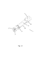
- Fig. 1 is a perspective view of an injection device 1 comprising a housing 2, a dose setting member 3 which is rotationally operable to set a desired dose, and an injection button 4 which is manually operable to cause a set dose to be expelled from the injection device 1.
- the housing 2 comprises a cartridge holding part 5 being adapted to accommodate a cartridge containing a liquid drug to be injected by means of the injection device 1.
- the injection device 1 is further provided with a display 6 adapted to display various relevant information, including the size of a dose being set.
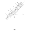
- Fig. 2 shows a dosing member 7, a mode locking member 8 and a dose setting member 3 for use in the injection device of Fig. 1 .
- the inner surface of the mode locking member 8 is provided with a first set of teeth 9, and the outer surface of the dosing member 7 is provided with a first set of mating teeth 10.
- the dosing member 7 and the mode locking member 8 may be positioned relatively to each other in such a manner that the first set of teeth 9 and the first set of mating teeth 10 engage, thereby rotationally locking the dosing member 7 and the mode locking member 8 to each other. This defines a first extreme position for the mode locking member 8. This will be described in further detail below.
- the outer surface of the mode locking member 8 is provided with a second set of teeth 11, and the inner surface of the dose setting member 3 is provided with a second set of mating teeth 12.
- the mode locking member 8 and the dose setting member 3 may be positioned relatively to each other in such a manner that the second set of teeth 11 and the second set of mating teeth 12 engage, thereby rotationally locking the mode locking member 8 and the dose setting member 3 to each other. This defines a second extreme position for the mode locking member 8. This will be described in further details below.
- Figs. 3-6 show selected parts of the injection device 1 of Fig. 1 . Thus, for the sake of clarity, only the parts which are essential for illustrating the operation of the injection device 1 are shown in these Figures.
- the injection device 1 is ready for setting a dose.
- the injection button 4 is positioned close to the dose setting member 3 and the mode locking member 8 is positioned in such a manner that the first set of teeth and the first set of mating teeth engage as described above, i.e. the mode locking member 8 is in the first extreme position.
- the mode locking member 8 is rotationally fixed relatively to the housing, and the dosing member 7 is therefore also rotationally fixed relatively to the housing in the situation illustrated in Fig. 3 .
- a piston rod 13 is positioned relatively close to the position of the dose setting member 3, thereby indicating that the cartridge (not shown) inserted in the injection device 1 is full or almost full.
- the dosing member 7 is connected to a dose rod 14 via a first thread, and the dose rod 14 is also connected to the piston rod 13 via a second thread.
- the first thread and the second thread in this example, have identical pitch. Accordingly, when the dose setting member 3 is rotated, the dose rod 14 is rotated along in a controlled manner preventing the piston rod 13 from moving during dose setting. During injection the dose rod 14 is moving axially, but is prevented from rotating, since the mode locking member 8 in this situation is in its second extreme position, and thereby the dosing member 7 and the mode locking member 8 are disengaged. Accordingly, since, in the situation illustrated in Fig. 3 , the dosing member 7 is prevented from rotating, the piston rod 13 is prevented from moving axially, and it is thereby prevented from pushing the piston in the cartridge, and thereby from causing liquid drug to be expelled from the injection device 1.
- the dose setting member 3 is operatively connected to the dose rod 14 in such a manner that rotating the dose setting member 3 causes the dose rod 14 to rotate. This will cause the dose rod 14 to move along the piston rod 13, due to the thread.
- the dose rod 14 is axially connected to a gearwheel 16 via a gearwheel slider (18 in Fig. 7 , not visible in Fig. 3 ).
- the gearwheel 16 is, via its teeth, engaged with a first rack 15 forming part of the injection button 4. Due to the connection between the dose rod 14 and the gearwheel 16 via the gearwheel slider, the gearwheel 16 is moved axially in a proximal direction when the dose rod 14 is rotated as described above.
- the gearwheel 16 is also, via its teeth, engaged with a second rack 17 which is operatively connected to the mode locking means 8. Due to this engagement the gearwheel 16 is caused to rotate when it is moved axially along with the dose rod 14. As a result, the injection button 4 is moved axially in a proximal direction with a gearing ration of 2:1, partly due to the axial movement of the gearwheel 16, and partly due to the movement of the first rack 15 as a consequence of the rotation of the gearwheel 16.
- Fig. 4 shows the injection device 1 in a position where a dose has been set. It is clear that the injection button 4 has been moved in a proximal direction as compared to the situation illustrated in Fig. 3 .
- the dose setting member 3 is shown with a part broken away in order to illustrate the relative position between the dose setting member 3 and the mode locking member 8.
- the second set of teeth 11 and the second set of mating teeth 12 do not engage in Fig. 4 . Accordingly, it is possible to rotate the dose setting member 3, i.e. it is still possible to increase or decrease the set dose.
- the user In order to inject the set dose, the user will position the injection needle (not shown) at a desired injection site. The user will then push the injection button 4 in order to return it to the position shown in Fig. 3 , thereby injecting the set dose.
- the first set of teeth (not shown) engage the first set of mating teeth (not shown), and the dosing member 7 is therefore prevented from performing a rotating movement. Pushing the injection button 4 will therefore not immediately result in the set dose being injected. Instead the following happens.
- the injection button 4 is provided with a first rack 15 which is engaging the gearwheel 16. Accordingly, pushing the injection button 4 will cause the gearwheel 16 to rotate.
- the gearwheel 16 is further engaging a second rack 17 which, as mentioned above, is operationally coupled to the mode locking means 8. Accordingly, rotating the gearwheel 16 causes the second rack 17, and thereby the mode locking means 8, to move in a proximal direction.
- the second set of teeth 11 and the second set of mating teeth 12 are moved into engagement while the second set of teeth and the second set of mating teeth are moved out of engagement, i.e. the mode locking means 8 is moved from the first extreme position to the second extreme position.
- the above procedure can be performed without the risk of accidentally rotating the dose setting member 3, i.e. it is ensured, due to the engagement of the second set of teeth 11 and the second set of mating teeth 12, that the initially set dose can not be accidentally increased or decreased during injection.
- Fig. 6 shows the injection device 1 in a position where the set dose has been injected.
- the injection button 4 has returned to the position of Fig. 3 .
- the piston rod 14 has been moved in the distal direction, thereby indicating that the piston in the cartridge has been moved correspondingly, and that the set dose has thereby been injected, and that the cartridge is no longer full.
- the mode locking member 8 remains in the second extreme position, i.e. the second set of teeth and the second set of mating teeth are kept in engagement. Accordingly, the mode locking member 8 will have to be moved manually to the first extreme position before the injection device 1 is once again ready for setting a new dose.
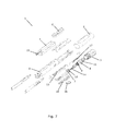
- Fig. 7 is an exploded view of the injection device of Fig. 1 . Accordingly, Fig. 7 gives a clear view of the individual parts of the injection device 1.
- Fig. 8 is a perspective view of an injection device 1 according to a second embodiment of the invention, the injection device 1 comprising a housing 2 and a dose setting member 3 which is rotationally operable to set a desired dose.
- the dose setting member 3 also functions as an injection button.
- the housing 2 comprises a cartridge holding part 5 being adapted to accommodate a cartridge containing a liquid drug to be injected by means of the injection device 1.
- the injection device 1 is of the kind in which energy is stored in a spring member during dose setting, the energy being released during injection and used for driving a piston rod in order to cause a set dose to be expelled from the injection device 1. This will also be explained further below.
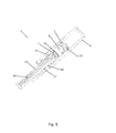
- Fig. 9 is a cross sectional view of the injection device 1 of Fig. 8 .
- a piston rod 13 and a compressible spring 19 are visible.
- the compressible spring 19 is arranged inside a dosage tube 20, and it is compressed during dose setting by means of spring compressing member 21 attached at the interior of the dosage tube 20. Thereby energy is stored in the compressible spring 19, and this energy is released during injection and used for driving the piston rod 13 in a distal direction, thereby pushing a piston 22 arranged inside a cartridge (not shown) in a distal direction and causing a set dose to be expelled from the injection device 1.
- the piston rod 13 is prevented from moving in a distal direction in the following manner.
- the first locking member 23 and the tube 24 are thereby prevented from performing relative rotation.
- rotary lock 25 prevents the piston rod 13 from rotating. Thereby the piston rod 13 is prevented from moving in a distal direction. This will be explained in further detail below with reference to Figs. 10-13 .
- the dose setting member 3 is prevented from performing rotational movement because a set of teeth arranged on a second locking member 26, being rotationally locked relatively to the housing 2, engages a set of teeth arranged in the interior of the dose setting member 3. This will also be explained in further detail below.
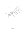
- Figs. 10-13 show selected parts of the injection device 1 of Fig. 8 . Thus, for the sake of clarity, only the parts which are essential for illustrating the operation of the injection device 1 are shown in these Figures.
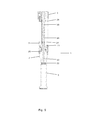
- Fig. 10 the injection device 1 is ready for setting a dose. It can be seen that the teeth arranged on the first locking member 23 engages the teeth arranged on the tube 24. Due to this engagement, and since the piston rod 13 is threadedly engaged to the first locking member 23, it will only be allowed to move in a distal direction if it spirals through the first locking member 23. However, as described above, the piston rod 13 is prevented from performing rotational movement due to the rotary lock (not visible in Fig. 10 ). Accordingly, the piston rod 13 is prevented from moving in a distal direction.
- the dose setting member 3 When it is desired to set a dose, the dose setting member 3 is dialled, thereby rotating dosage tube 20 and spring compressing member (not visible) arranged inside dosage tube. This causes the spring compressing member (not visible) to climb the thread of the piston rod 13, thereby compressing the spring (not visible) and moving the dosage tube 20 in a proximal direction.
- Fig. 11 shows the injection device 1 in a position where a dose has been set. It can be seen that the dosage tube 20 has been moved in a proximal direction. The set of teeth arranged on the first locking member 23 still engages the set of teeth arranged on the tube 24, i.e. the piston rod 13 is still prevented from moving in a distal direction as described above.
- the dose setting member 3 When it is desired to inject the set dose, the dose setting member 3 is pushed in a distal direction. Initially, this will push the set of teeth arranged on the second locking member 26 into engagement with the set of teeth arranged in the interior of the dose setting member 3, thereby preventing further rotation of the dose setting member 3, i.e. preventing further setting of the dose. During this initial movement, the set of teeth arranged on the first locking member 23 continues to engage the set of teeth arranged on the tube 24. Thus, during an initial time period the dose setting member 3 will be prevented from rotating while the piston rod 13 will be prevented from moving in a distal direction, i.e. dose setting as well as injection is prevented at the same time. Thereby the risk that dose setting as well as injection is possible at a certain point in time is eliminated.
- Pushing the dose setting member 3 further in a distal direction pushes the tube 24 in a distal direction, thereby moving the set of teeth arranged on the tube 24 out of engagement with the set of teeth arranged on the first locking member 23.
- the first locking member 23 is allowed to rotate.
- the piston rod 13 is allowed to move in a distal direction while causing rotation of the first locking member 23.
- the energy stored in the spring is released, and the released energy is used for driving the piston rod 13 in a distal direction, thereby causing the set dose to be expelled.
- Fig. 12 shows the injection device 1 in a position where the dose setting member 3 has been pushed in a distal direction sufficiently to cause the set of teeth arranged on the second locking member 26 to engage the set of teeth arranged in the interior of the dose setting member 3, and sufficiently to cause the set of teeth arranged on the first locking member 23 to disengage the set of teeth arranged on the tube 24.
- the energy stored in the spring has only just been released, and the piston rod 13 has therefore not yet been moved.
- Fig. 13 shows the injection device 1 in a position where the set dose has been injected.
- the dosage tube 20 has been moved back to the initial position, and the piston rod 13 has been moved distally.
- the set of teeth arranged on the first locking member 23 is still out of engagement with the set of teeth arranged on the tube 24, and the set of teeth arranged on the second locking member 26 is still engaging the set of teeth arranged in the interior of the dose setting member 3.
- relieving the pressure on the dose setting member 3 will cause a reversal of this situation.
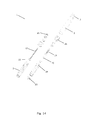
- Fig. 14 is an exploded view of the injection device 1 of Fig. 8 . Accordingly, Fig. 14 gives a clear view of the individual parts of the injection device 1.
Landscapes
- Health & Medical Sciences (AREA)
- Vascular Medicine (AREA)
- Engineering & Computer Science (AREA)
- Anesthesiology (AREA)
- Biomedical Technology (AREA)
- Heart & Thoracic Surgery (AREA)
- Hematology (AREA)
- Life Sciences & Earth Sciences (AREA)
- Animal Behavior & Ethology (AREA)
- General Health & Medical Sciences (AREA)
- Public Health (AREA)
- Veterinary Medicine (AREA)
- Infusion, Injection, And Reservoir Apparatuses (AREA)
Abstract
Description
- The present invention relates to an injection device, in particular an injection device which is suitable for use for self-medication, e.g. for administering insulin to persons with diabetes, or for administering growth hormone. More particularly, the present invention relates to an injection device as defined above and which is capable of preventing unintended expelling of liquid drug during dose setting, and unintended movement of a dose setting mechanism during injection of a set dose.
- When using injection devices as defined above, a desired dose is normally set by means of a dose setting mechanism. When the dose has been set, an injection needle is positioned at a desired injection position, and the set dose is injected by means of an injection mechanism, normally including a manually operable injection button and a piston rod cooperating with a piston of a cartridge containing the drug to be injected.
- If it is possible for the piston rod to move in a distal direction during setting of a dose, there is a risk that liquid drug is accidentally spilled during dose setting. Furthermore, if it is possible for the piston rod to move in a proximal direction during dose setting, the pressure applied to the piston from the piston rod may decrease, possibly even forming a gap between the piston and the piston rod, and thereby there is a risk that blood is sucked into the cartridge when the injection needle of the device is subsequently inserted at the injection site. Furthermore, if it is possible for the dose setting mechanism to move during injection of an initially set dose, the set dose may accidentally be increased or decreased during the injection, and the actually injected dose may thereby be unknown. This is very undesirable. It is therefore desirable to be able to prevent such undesired movements of the piston rod and the dose setting mechanism, respectively.
- Attempts have been made to solve the problem described above in injection devices of the kind having a cylindrical scale drum with a helical spiral of numbers written thereon. When a dose is set in such an injection device the cylindrical scale drum is dialled outwards, and a number corresponding to the set dose will show in a window on the injection device.
US 2004/0059299 discloses an injection device of this kind. The injection device is provided with a dose setting element which, during dose setting, is coupled rotationally as well as axially to the scale drum. During injection the dose setting member is prevented from rotating. At the same time the dose setting element is coupled to a dose rod which can be rotated along a piston rod via a gearwheel providing a gearing corresponding to the pitch of the scale drum. Since the dose setting element and the scale drum are axially coupled during dose setting, the dose rod is rotated in a controlled manner, thereby preventing the piston rod from moving during dose setting. Since the dose setting element is prevented from rotating during injection, the dose rod is pushed back without performing a rotational movement, thereby causing an advancing movement of the piston rod. -
EP 1 304 129 - The injection device disclosed in
EP 1 304 129 - It is a disadvantage that the mechanism which prevents undesired movements of the piston rod during dose setting is connected to the scale drum, since the mechanism therefore can not readily be applied to injection devices which are not provided with a cylindrical scale drum. Furthermore, it is sometimes desirable to design an injection device without such a cylindrical scale drum, e.g. in order to use the space occupied by a scale drum for other purposes, e.g. additional electronics for controlling the injection device, or simply because a different counter mechanism is desired. However, it is still desirable to be able to overcome the problems outlined above in such an injection device.
- It is, thus, an object of the invention to provide an injection device in which it is possible to prevent undesired spilling of drug during dose setting, as well as undesired movements of the dose setting means during injection.
- It is a further object of the invention to provide a relatively flat injection device which is capable of preventing undesired spilling of drug during dose setting, as well as undesired movements of the dose setting means during injection.
- It is an even further object of the invention to provide an injection device without a cylindrical scale drum, and which is capable of preventing undesired spilling of drug during dose setting, as well as undesired movements of the dose setting means during injection.
- According to the invention the above and other objects are fulfilled by providing an injection device comprising:
- a housing,
- a dose setting member being operable to set a desired dose,
- a piston rod adapted to cooperate with a piston to cause a set dose to be expelled from the injection device,
- mode locking means adapted to be in a first extreme position, in which the piston rod is prevented from cooperating with the piston, and a second extreme position, in which the dose setting member is prevented from being operated to set a dose,
- In the present context the term 'housing' should be interpreted to mean a part which at least substantially encloses the remaining parts of the injection device, thereby forming a kind of boundary of the injection device. The housing may be provided with one or more completely closed walls or wall parts, and/or it may be provided with one or more relatively open walls or wall parts, e.g. in the form of a grid.
- The dose setting member is a part of the injection device which the user operates manually in order to set a desired dose. This will be explained further below.
- The piston is preferably positioned inside a cartridge containing a relevant liquid drug. The piston rod and the piston are preferably positioned in abutment with each other in such a manner that moving the piston rod in a distal direction will cause the piston to be moved in a distal direction, thereby pushing liquid drug out of the cartridge. The cartridge may form part of the injection device. In this case the injection device is of the kind which is delivered with the liquid drug already present in the injection device, and when this drug has been delivered, the injection device is discarded. Alternatively, the cartridge may be a separate, removable part. In this case an empty cartridge, and optionally one or more additional parts, can be replaced by a new cartridge, i.e. only the empty cartridge, and optionally the additional part(s), is discarded while the injection device is reused.
- The injection device may be of a kind in which energy is stored in a spring member during dose setting. Subsequently, during injection, the stored energy is released and used for driving the piston rod, thereby causing a set dose to be expelled from the injection device. Such an injection device has the advantage that it is easy to use for persons having poor dexterity or low finger strength, since the user does not have to provide the force needed to cause the set dose to be expelled from the injection device.
- Alternatively, the injection device may be of a manually operable kind, where the user has to provide the force needed to expel a set dose from the injection device, or it may be of a motor driven kind.
- The mode locking means is adapted to be in a first extreme position and in a second extreme position. When the mode locking means is in the first extreme position the piston rod is prevented from cooperating with the piston. Accordingly, the piston can not be accidentally moved when the mode locking means is in the first extreme position, and thereby liquid drug can not be accidentally spilled. Furthermore, it is prevented that a gap may form between the piston and the piston rod, and thereby the risk of sucking blood into the cartridge when the injection needle is subsequently inserted at the injection site, is minimised. Since the mode locking means is adapted to be in the first extreme position during dose setting, the mode locking means prevents undesired spilling of liquid drug, as well as undesired blood in the cartridge, during dose setting.
- On the other hand, when the mode locking means is in the second extreme position the dose setting member is prevented from being operated to set a dose. Accordingly, the dose setting member can not be accidentally operated when the mode locking means is in the second extreme position. Since the mode locking means is adapted to be in the second extreme position during injection of a set dose, it is thereby prevented that an initially set dose is accidentally increased or decreased during injection. Thereby it is ensured that the dose which is actually injected is in fact the initially set, desired dose.
- Thus, the mode locking means locks the piston rod during dose setting and the dose setting means during injection of a set dose.
- The mode locking means does not form part of a cylindrical scale drum, neither is the operation of the mode locking means dependent on the movements of such a scale drum. Accordingly, it is possible to apply the mode locking means to injection devices where a cylindrical scale drum for some reason has been omitted.
- Thus, a mechanically simple solution to the above problem has been provided. Furthermore, the present invention provides the possibility of producing a relatively flat injection device having a mode locking mechanism, since the mode locking mechanism can be provided at a relatively small diameter. This is very advantageous.
- In one embodiment the piston rod may be prevented from moving in a distal direction when the mode locking means is in the first extreme position. If the injection device has an elongated shape, i.e. if the injection device is a so-called 'pen-shaped' injection device, the piston rod is normally a relatively stiff elongated member mounted in the injection device in such a manner that it may perform substantially linear movements along its longitudinal axis. Furthermore, the piston rod is mounted in such a manner that linear movements of the piston rod in a distal direction, i.e. towards the position of a mounted injection needle, causes a corresponding movement in the distal direction of the piston in the cartridge, and thereby expelling of liquid drug from the injection device. The injection device is further provided with manually operable injection means, e.g. in the form of an injection button. After a desired dose has been set the user operates the injection means, e.g. pushing an injection button. This causes a movement of the piston rod in a distal direction and by an amount corresponding to the set dose. Thereby the set dose is injected by the injection device.
- Alternatively or additionally, the dose setting member may be rotationally operable to set a desired dose, and the dose setting member may be prevented from performing a rotational movement when the mode locking means is in the second extreme position. In this case the dose setting member may be in the form of a rotational dose knob which can be manually dialled in order to set a desired dose. Dialling the dose setting member preferably causes an injection button to be moved at least substantially linearly out of the housing in a proximal direction, i.e. in a direction away from the position of the injection needle. The set dose is preferably displayed, e.g. on an electronic display mounted on the housing. Preventing the dose setting member from performing a rotational movement, thus, prevents the dose setting member from being operated to set a dose, including changing a previously set dose, during injection.
- The dose setting member may, e.g., be prevented from performing a rotational movement by means of engaging sets of teeth provided on the mode locking means and on the dose setting member, and the sets of teeth may be moved into engagement when the mode locking means is moved into the second extreme position. Alternatively, the dose setting member may be prevented from performing a rotational movement due to abutment between mating surfaces, or this feature may be provided in any other suitable manner and using any other suitable means.
- The mode locking means may further be adapted to be in an intermediate position in which the piston rod is prevented from cooperating with the piston, and the dose setting member is prevented from being operated to set a dose, and the mode locking means may be adapted to be in the intermediate position when being moved between the first and the second extreme positions. Thus, when the mode locking means is in the intermediate position, movement of the piston rod as well as operation of the dose setting means is prevented. Accordingly, when the mode locking means is moved between the first and the second extreme positions, the piston rod can not be accidentally moved, and the dose setting means can not be accidentally operated. Thereby the first and second extreme positions are well separated in the sense that there is no overlap at all between the two extreme positions, i.e. it will not be possible for the mode locking means to be in a position where it is possible for the piston rod to cooperate with the piston while it is also possible to operate the dose setting member to set a dose. This is very advantageous.
- According to one embodiment the mode locking means may be provided with a first set of teeth, and the piston rod may be operatively connected to a dosing member, the dosing member being provided with a first set of mating teeth, and the first set of teeth and the first set of mating teeth may engage when the mode locking means is in the first extreme position. The operative connection between the piston rod and the dosing member may preferably be provided by means of a dose rod, preferably in the following manner. The piston rod may be engaging the dose rod via a first thread, and the dose rod may further be engaging the dosing member via a second thread having the same pitch as the first thread. In this case the dosing member ensures that the dose rod is rotated in a controlled manner which prevents the piston rod from moving during dose setting. On the other hand when the mode locking means is in the second extreme position, i.e. during injection, the first set of teeth and the first set of mating teeth preferably do not engage. Accordingly, in this situation the dosing member will be able to rotate, and it will be caused to do so due to the dose rod advancing axially, but being prevented from rotating.
- Thus, when the first set of teeth and the first set of mating teeth engage, the dosing member is prevented from performing a rotational movement relatively to the mode locking means. Since the piston rod and the dosing member are operatively connected, the piston rod is thereby prevented from being operated via the dosing member.
- Alternatively or additionally, the mode locking means may be provided with a second set of teeth, and the dose setting member may be provided with a second set of mating teeth, and the second set of teeth and the second set of mating teeth may engage when the mode locking means is in the second extreme position. As described above, the dose setting member will be prevented from performing a rotational movement when the second set of teeth and the second set of mating teeth engage. In the case that the dose setting member is rotationally operable to set a dose, the engagement thereby prevents the dose setting member from being operated to set a dose.
- The mode locking means may be rotationally locked to the housing, i.e. the mode locking means may be prevented from performing rotational movements relatively to the housing. Alternatively, the mode locking means may be allowed to rotate relatively to the housing if the mode locking means is instead rotationally locked to one or more elements of the injection device performing 'reversible movements' during dose setting and injection, respectively. In the present context the term 'reversible movement' should be understood as a movement which rotates the relevant element relatively to the housing through a specific angle and in a specific direction during dose setting, and through the same angle in the opposite direction during injection. Thus, the relevant element, and thereby the mode locking means, is always returned to the initial angular position.
- The injection device may further comprise an injection button being operable to cause the piston rod to cooperate with the piston to cause a set dose to be expelled from the injection device, the injection button being operatively connected to the mode locking means in such a manner that when the injection button is operated to cause a set dose to be expelled from the injection device, the mode locking means is automatically moved from the first extreme position to the second extreme position. According to this embodiment the injection device is preferably operated in the following manner.
- When it is desired to inject a dose of liquid drug the user sets the desired dose by manually operating the dose setting member. It may be necessary to manually move the mode locking means into the first extreme position prior to setting the dose. When the desired dose has been set, the injection needle is inserted in a desired injection position, and subsequently the injection button is operated. Initially, this operation will result in the mode locking means being moved from the first extreme position to the second extreme position, preferably via an intermediate position as described above. When the mode locking means has been moved into the second extreme position it will be possible to operate the piston rod, and further operation of the injection button will therefore cause the set dose to be expelled from the injection device.
- According to a preferred embodiment, the mode locking means may be adapted to be operated independently of a cylindrical scale drum. Thereby it is possible to apply the mode locking feature in an injection device which does not comprise such a cylindrical scale drum.
- The invention will now be described in further details with reference to the accompanying drawings in which
-
Fig. 1 is a perspective view of an injection device according to a first embodiment of the invention, -
Fig. 2 shows a dosing member, a mode locking member and a dose setting member for use in the injection device ofFig. 1 , -
Figs. 3-6 show selected parts of the injection device ofFig. 1 at various positions during operation of the injection device, -
Fig. 7 is an exploded view of the injection device ofFig. 1 , -
Fig. 8 is a perspective view of an injection device according to a second embodiment of the invention, -
Fig. 9 is a cross sectional view of the injection device ofFig. 8 , -
Figs. 10-13 show selected parts of the injection device ofFig. 8 at various positions during operation of the injection device, and -
Fig. 14 is an exploded view of the injection device ofFig. 8 . -
Fig. 1 is a perspective view of aninjection device 1 comprising ahousing 2, adose setting member 3 which is rotationally operable to set a desired dose, and aninjection button 4 which is manually operable to cause a set dose to be expelled from theinjection device 1. Thehousing 2 comprises acartridge holding part 5 being adapted to accommodate a cartridge containing a liquid drug to be injected by means of theinjection device 1. Theinjection device 1 is further provided with adisplay 6 adapted to display various relevant information, including the size of a dose being set. -
Fig. 2 shows adosing member 7, amode locking member 8 and adose setting member 3 for use in the injection device ofFig. 1 . The inner surface of themode locking member 8 is provided with a first set ofteeth 9, and the outer surface of thedosing member 7 is provided with a first set ofmating teeth 10. Thedosing member 7 and themode locking member 8 may be positioned relatively to each other in such a manner that the first set ofteeth 9 and the first set ofmating teeth 10 engage, thereby rotationally locking thedosing member 7 and themode locking member 8 to each other. This defines a first extreme position for themode locking member 8. This will be described in further detail below. - Furthermore, the outer surface of the
mode locking member 8 is provided with a second set ofteeth 11, and the inner surface of thedose setting member 3 is provided with a second set ofmating teeth 12. Themode locking member 8 and thedose setting member 3 may be positioned relatively to each other in such a manner that the second set ofteeth 11 and the second set ofmating teeth 12 engage, thereby rotationally locking themode locking member 8 and thedose setting member 3 to each other. This defines a second extreme position for themode locking member 8. This will be described in further details below. -
Figs. 3-6 show selected parts of theinjection device 1 ofFig. 1 . Thus, for the sake of clarity, only the parts which are essential for illustrating the operation of theinjection device 1 are shown in these Figures. - In
Fig. 3 theinjection device 1 is ready for setting a dose. Thus, theinjection button 4 is positioned close to thedose setting member 3 and themode locking member 8 is positioned in such a manner that the first set of teeth and the first set of mating teeth engage as described above, i.e. themode locking member 8 is in the first extreme position. Themode locking member 8 is rotationally fixed relatively to the housing, and thedosing member 7 is therefore also rotationally fixed relatively to the housing in the situation illustrated inFig. 3 . Apiston rod 13 is positioned relatively close to the position of thedose setting member 3, thereby indicating that the cartridge (not shown) inserted in theinjection device 1 is full or almost full. - The
dosing member 7 is connected to adose rod 14 via a first thread, and thedose rod 14 is also connected to thepiston rod 13 via a second thread. The first thread and the second thread, in this example, have identical pitch. Accordingly, when thedose setting member 3 is rotated, thedose rod 14 is rotated along in a controlled manner preventing thepiston rod 13 from moving during dose setting. During injection thedose rod 14 is moving axially, but is prevented from rotating, since themode locking member 8 in this situation is in its second extreme position, and thereby thedosing member 7 and themode locking member 8 are disengaged. Accordingly, since, in the situation illustrated inFig. 3 , thedosing member 7 is prevented from rotating, thepiston rod 13 is prevented from moving axially, and it is thereby prevented from pushing the piston in the cartridge, and thereby from causing liquid drug to be expelled from theinjection device 1. - When a dose is to be set, the user rotates the
dose setting member 3. Thedose setting member 3 is operatively connected to thedose rod 14 in such a manner that rotating thedose setting member 3 causes thedose rod 14 to rotate. This will cause thedose rod 14 to move along thepiston rod 13, due to the thread. Thedose rod 14 is axially connected to agearwheel 16 via a gearwheel slider (18 inFig. 7 , not visible inFig. 3 ). Thegearwheel 16 is, via its teeth, engaged with afirst rack 15 forming part of theinjection button 4. Due to the connection between thedose rod 14 and thegearwheel 16 via the gearwheel slider, thegearwheel 16 is moved axially in a proximal direction when thedose rod 14 is rotated as described above. Thegearwheel 16 is also, via its teeth, engaged with asecond rack 17 which is operatively connected to the mode locking means 8. Due to this engagement thegearwheel 16 is caused to rotate when it is moved axially along with thedose rod 14. As a result, theinjection button 4 is moved axially in a proximal direction with a gearing ration of 2:1, partly due to the axial movement of thegearwheel 16, and partly due to the movement of thefirst rack 15 as a consequence of the rotation of thegearwheel 16. -
Fig. 4 shows theinjection device 1 in a position where a dose has been set. It is clear that theinjection button 4 has been moved in a proximal direction as compared to the situation illustrated inFig. 3 . InFig. 4 thedose setting member 3 is shown with a part broken away in order to illustrate the relative position between thedose setting member 3 and themode locking member 8. As can be seen, the second set ofteeth 11 and the second set ofmating teeth 12 do not engage inFig. 4 . Accordingly, it is possible to rotate thedose setting member 3, i.e. it is still possible to increase or decrease the set dose. - In order to inject the set dose, the user will position the injection needle (not shown) at a desired injection site. The user will then push the
injection button 4 in order to return it to the position shown inFig. 3 , thereby injecting the set dose. However, as described above the first set of teeth (not shown) engage the first set of mating teeth (not shown), and thedosing member 7 is therefore prevented from performing a rotating movement. Pushing theinjection button 4 will therefore not immediately result in the set dose being injected. Instead the following happens. - As mentioned above, the
injection button 4 is provided with afirst rack 15 which is engaging thegearwheel 16. Accordingly, pushing theinjection button 4 will cause thegearwheel 16 to rotate. Thegearwheel 16 is further engaging asecond rack 17 which, as mentioned above, is operationally coupled to the mode locking means 8. Accordingly, rotating thegearwheel 16 causes thesecond rack 17, and thereby the mode locking means 8, to move in a proximal direction. Thereby the second set ofteeth 11 and the second set ofmating teeth 12 are moved into engagement while the second set of teeth and the second set of mating teeth are moved out of engagement, i.e. the mode locking means 8 is moved from the first extreme position to the second extreme position. - This situation is illustrated in
Fig. 5 . It is clear that the second set ofteeth 11 and the second set ofmating teeth 12 have been moved into engagement, and that the first set of teeth (not visible) and the first set ofmating teeth 10 have been moved out of engagement. Accordingly, it is now no longer possible to rotate thedose setting member 3 to increase or decrease the set dose. However, thedosing member 7 is now free to rotate relatively to themode locking member 8. Accordingly, further pushing of theinjection button 4 will result in thegearwheel 16 performing a rotational movement and an axial movement in a distal direction. As a consequence thedose rod 14 and thepiston rod 13 will move as described above. Since thedose rod 14 is now unable to rotate, it will cause thedosing member 7 to rotate due to the engaging thread. Thereby thedosing member 7 will produce a clicking sound in cooperation with a non-rotating, axially spring loaded second dosing member (not shown). - The above procedure can be performed without the risk of accidentally rotating the
dose setting member 3, i.e. it is ensured, due to the engagement of the second set ofteeth 11 and the second set ofmating teeth 12, that the initially set dose can not be accidentally increased or decreased during injection. -
Fig. 6 shows theinjection device 1 in a position where the set dose has been injected. Thus, theinjection button 4 has returned to the position ofFig. 3 . As compared toFig. 3 thepiston rod 14 has been moved in the distal direction, thereby indicating that the piston in the cartridge has been moved correspondingly, and that the set dose has thereby been injected, and that the cartridge is no longer full. It is clear fromFig. 6 that themode locking member 8 remains in the second extreme position, i.e. the second set of teeth and the second set of mating teeth are kept in engagement. Accordingly, themode locking member 8 will have to be moved manually to the first extreme position before theinjection device 1 is once again ready for setting a new dose. -
Fig. 7 is an exploded view of the injection device ofFig. 1 . Accordingly,Fig. 7 gives a clear view of the individual parts of theinjection device 1. -
Fig. 8 is a perspective view of aninjection device 1 according to a second embodiment of the invention, theinjection device 1 comprising ahousing 2 and adose setting member 3 which is rotationally operable to set a desired dose. Thedose setting member 3 also functions as an injection button. This will be described in further detail below. Thehousing 2 comprises acartridge holding part 5 being adapted to accommodate a cartridge containing a liquid drug to be injected by means of theinjection device 1. Theinjection device 1 is of the kind in which energy is stored in a spring member during dose setting, the energy being released during injection and used for driving a piston rod in order to cause a set dose to be expelled from theinjection device 1. This will also be explained further below. -
Fig. 9 is a cross sectional view of theinjection device 1 ofFig. 8 . InFig. 9 apiston rod 13 and acompressible spring 19 are visible. Thecompressible spring 19 is arranged inside adosage tube 20, and it is compressed during dose setting by means ofspring compressing member 21 attached at the interior of thedosage tube 20. Thereby energy is stored in thecompressible spring 19, and this energy is released during injection and used for driving thepiston rod 13 in a distal direction, thereby pushing apiston 22 arranged inside a cartridge (not shown) in a distal direction and causing a set dose to be expelled from theinjection device 1. - During dose setting the
piston rod 13 is prevented from moving in a distal direction in the following manner. A set of teeth arranged on afirst locking member 23, being threadedly engaged with thepiston rod 13, engages a set of teeth arranged on atube 24 which is rotationally locked to thehousing 2. Thefirst locking member 23 and thetube 24 are thereby prevented from performing relative rotation. At the same time,rotary lock 25 prevents thepiston rod 13 from rotating. Thereby thepiston rod 13 is prevented from moving in a distal direction. This will be explained in further detail below with reference toFigs. 10-13 . - During injection the
dose setting member 3 is prevented from performing rotational movement because a set of teeth arranged on asecond locking member 26, being rotationally locked relatively to thehousing 2, engages a set of teeth arranged in the interior of thedose setting member 3. This will also be explained in further detail below. -
Figs. 10-13 show selected parts of theinjection device 1 ofFig. 8 . Thus, for the sake of clarity, only the parts which are essential for illustrating the operation of theinjection device 1 are shown in these Figures. - In
Fig. 10 theinjection device 1 is ready for setting a dose. It can be seen that the teeth arranged on the first lockingmember 23 engages the teeth arranged on thetube 24. Due to this engagement, and since thepiston rod 13 is threadedly engaged to the first lockingmember 23, it will only be allowed to move in a distal direction if it spirals through the first lockingmember 23. However, as described above, thepiston rod 13 is prevented from performing rotational movement due to the rotary lock (not visible inFig. 10 ). Accordingly, thepiston rod 13 is prevented from moving in a distal direction. - When it is desired to set a dose, the
dose setting member 3 is dialled, thereby rotatingdosage tube 20 and spring compressing member (not visible) arranged inside dosage tube. This causes the spring compressing member (not visible) to climb the thread of thepiston rod 13, thereby compressing the spring (not visible) and moving thedosage tube 20 in a proximal direction. -
Fig. 11 shows theinjection device 1 in a position where a dose has been set. It can be seen that thedosage tube 20 has been moved in a proximal direction. The set of teeth arranged on the first lockingmember 23 still engages the set of teeth arranged on thetube 24, i.e. thepiston rod 13 is still prevented from moving in a distal direction as described above. - When it is desired to inject the set dose, the
dose setting member 3 is pushed in a distal direction. Initially, this will push the set of teeth arranged on thesecond locking member 26 into engagement with the set of teeth arranged in the interior of thedose setting member 3, thereby preventing further rotation of thedose setting member 3, i.e. preventing further setting of the dose. During this initial movement, the set of teeth arranged on the first lockingmember 23 continues to engage the set of teeth arranged on thetube 24. Thus, during an initial time period thedose setting member 3 will be prevented from rotating while thepiston rod 13 will be prevented from moving in a distal direction, i.e. dose setting as well as injection is prevented at the same time. Thereby the risk that dose setting as well as injection is possible at a certain point in time is eliminated. - Pushing the
dose setting member 3 further in a distal direction pushes thetube 24 in a distal direction, thereby moving the set of teeth arranged on thetube 24 out of engagement with the set of teeth arranged on the first lockingmember 23. Thereby the first lockingmember 23 is allowed to rotate. Accordingly, thepiston rod 13 is allowed to move in a distal direction while causing rotation of the first lockingmember 23. At the same time the energy stored in the spring is released, and the released energy is used for driving thepiston rod 13 in a distal direction, thereby causing the set dose to be expelled. -
Fig. 12 shows theinjection device 1 in a position where thedose setting member 3 has been pushed in a distal direction sufficiently to cause the set of teeth arranged on thesecond locking member 26 to engage the set of teeth arranged in the interior of thedose setting member 3, and sufficiently to cause the set of teeth arranged on the first lockingmember 23 to disengage the set of teeth arranged on thetube 24. However, the energy stored in the spring has only just been released, and thepiston rod 13 has therefore not yet been moved. -
Fig. 13 shows theinjection device 1 in a position where the set dose has been injected. Thus, thedosage tube 20 has been moved back to the initial position, and thepiston rod 13 has been moved distally. The set of teeth arranged on the first lockingmember 23 is still out of engagement with the set of teeth arranged on thetube 24, and the set of teeth arranged on thesecond locking member 26 is still engaging the set of teeth arranged in the interior of thedose setting member 3. However, relieving the pressure on thedose setting member 3 will cause a reversal of this situation. -
Fig. 14 is an exploded view of theinjection device 1 ofFig. 8 . Accordingly,Fig. 14 gives a clear view of the individual parts of theinjection device 1.
Claims (8)
- An injection device (1) comprising:- a housing (2),- a dose setting member (3) being operable to set a desired dose,- a piston rod (13) adapted to cooperate with a piston to cause a set dose to be expelled from the injection device (1),- mode locking means (8; 23, 24, 26) adapted to be in a first extreme position, wherein the piston rod (13) is prevented from cooperating with the piston, and a second extreme position, wherein the dose setting member (3) is prevented from being operated to set a dose,- an injection button (4; 3) being operable to cause the piston rod (13) to cooperate with the piston to cause a set dose to be expelled from the injection device (1), the injection button (4; 3) being operatively connected to the mode locking means (8; 23, 24, 26) in such a manner that when the injection button (4; 3) is operated to cause a set dose to be expelled from the injection device (1), the mode locking means (8; 23, 24, 26) is automatically moved from the first extreme position to the second extreme position, andwherein the mode locking means (8; 23, 24, 26) is adapted to be in the first extreme position during dose setting and in the second extreme position during injection of a set dose.
- An injection device according to claim 1, wherein the piston rod (13) is prevented from moving in a distal direction when the mode locking means (8; 23, 24, 26) is in the first extreme position.
- An injection device according to claim 1 or 2, wherein the dose setting member (3) is rotationally operable to set a desired dose, and wherein the dose setting member (3) is prevented from performing a rotational movement when the mode locking means (8; 23, 24, 26) is in the second extreme position.
- An injection device according to any of the preceding claims, wherein the mode locking means (8; 23, 24, 26) is further adapted to be in an intermediate position in which the piston rod (13) is prevented from cooperating with the piston, and the dose setting member (3) is prevented from being operated to set a dose, the mode locking means (8; 23, 24, 26) being adapted to be in the intermediate position when being moved between the first and the second extreme positions.
- An injection device according to any of the preceding claims, wherein the mode locking means (8) is provided with a first set of teeth (9), and wherein the piston rod (13) is operatively connected to a dosing member (7), the dosing member being provided with a first set of mating teeth (10), and wherein the first set of teeth (9) and the first set of mating teeth (10) engage when the mode locking means (8) is in the first extreme position.
- An injection device according to any of the preceding claims, wherein the mode locking means (8) is provided with a second set of teeth (11), and the dose setting member (3) is provided with a second set of mating teeth (12), and wherein the second set of teeth (11) and the second set of mating teeth (12) engage when the mode locking (8) means is in the second extreme position.
- An injection device according to any of the preceding claims, wherein the mode locking means (8; 23, 24, 26) is rotationally locked to the housing (2).
- An injection device according to any of the preceding claims, wherein the mode locking means (8; 23, 24, 26) is adapted to be operated independently of a cylindrical scale drum.
Priority Applications (1)
| Application Number | Priority Date | Filing Date | Title |
|---|---|---|---|
| EP11172344.1A EP2374488B1 (en) | 2006-05-18 | 2007-05-03 | An injection device with mode locking means |
Applications Claiming Priority (3)
| Application Number | Priority Date | Filing Date | Title |
|---|---|---|---|
| EP06010278 | 2006-05-18 | ||
| EP11172344.1A EP2374488B1 (en) | 2006-05-18 | 2007-05-03 | An injection device with mode locking means |
| EP07728747A EP2023982B1 (en) | 2006-05-18 | 2007-05-03 | An injection device with mode locking means |
Related Parent Applications (2)
| Application Number | Title | Priority Date | Filing Date |
|---|---|---|---|
| EP07728747.2 Division | 2007-05-03 | ||
| EP07728747A Division EP2023982B1 (en) | 2006-05-18 | 2007-05-03 | An injection device with mode locking means |
Publications (3)
| Publication Number | Publication Date |
|---|---|
| EP2374488A2 true EP2374488A2 (en) | 2011-10-12 |
| EP2374488A3 EP2374488A3 (en) | 2011-12-21 |
| EP2374488B1 EP2374488B1 (en) | 2018-03-21 |
Family
ID=37025088
Family Applications (2)
| Application Number | Title | Priority Date | Filing Date |
|---|---|---|---|
| EP11172344.1A Active EP2374488B1 (en) | 2006-05-18 | 2007-05-03 | An injection device with mode locking means |
| EP07728747A Not-in-force EP2023982B1 (en) | 2006-05-18 | 2007-05-03 | An injection device with mode locking means |
Family Applications After (1)
| Application Number | Title | Priority Date | Filing Date |
|---|---|---|---|
| EP07728747A Not-in-force EP2023982B1 (en) | 2006-05-18 | 2007-05-03 | An injection device with mode locking means |
Country Status (12)
| Country | Link |
|---|---|
| US (1) | US9192727B2 (en) |
| EP (2) | EP2374488B1 (en) |
| JP (1) | JP5253387B2 (en) |
| CN (2) | CN102327655B (en) |
| AU (1) | AU2007253481B2 (en) |
| BR (1) | BRPI0712028A2 (en) |
| CA (1) | CA2652396C (en) |
| DK (1) | DK2023982T3 (en) |
| ES (1) | ES2389866T3 (en) |
| PL (1) | PL2023982T3 (en) |
| RU (1) | RU2433840C2 (en) |
| WO (1) | WO2007134954A1 (en) |
Families Citing this family (76)
| Publication number | Priority date | Publication date | Assignee | Title |
|---|---|---|---|---|
| US6663602B2 (en) | 2000-06-16 | 2003-12-16 | Novo Nordisk A/S | Injection device |
| WO2003068290A2 (en) | 2002-02-11 | 2003-08-21 | Antares Pharma, Inc. | Intradermal injector |
| PL1804865T3 (en) | 2004-10-21 | 2010-03-31 | Novo Nordisk As | Screw-in mechanism for wound pens |
| JP4903160B2 (en) * | 2005-01-18 | 2012-03-28 | ウォックハート アメリカズ インコーポレイテッド | Pen-type drug injection device |
| WO2006079064A1 (en) | 2005-01-24 | 2006-07-27 | Antares Pharma, Inc. | Prefilled needle assisted jet injector |
| JP4979686B2 (en) | 2005-04-24 | 2012-07-18 | ノボ・ノルデイスク・エー/エス | Injection device |
| WO2007131013A1 (en) | 2006-05-03 | 2007-11-15 | Antares Pharma, Inc. | Two-stage reconstituting injector |
| US9144648B2 (en) | 2006-05-03 | 2015-09-29 | Antares Pharma, Inc. | Injector with adjustable dosing |
| DE602007004972D1 (en) | 2006-05-16 | 2010-04-08 | Novo Nordisk As | GEARING MECHANISM FOR AN INJECTION DEVICE |
| JP5253387B2 (en) | 2006-05-18 | 2013-07-31 | ノボ・ノルデイスク・エー/エス | Injection device with mode locking means |
| PL2073871T3 (en) | 2006-09-29 | 2013-08-30 | Novo Nordisk As | An injection device with electronic detecting means |
| WO2008116766A1 (en) * | 2007-03-23 | 2008-10-02 | Novo Nordisk A/S | An injection device comprising a locking nut |
| ATE520435T1 (en) | 2007-08-17 | 2011-09-15 | Novo Nordisk As | MEDICAL DEVICE WITH VALUE SENSOR |
| US10420880B2 (en) | 2007-10-02 | 2019-09-24 | West Pharma. Services IL, Ltd. | Key for securing components of a drug delivery system during assembly and/or transport and methods of using same |
| CN101868273B (en) | 2007-10-02 | 2014-10-15 | 莱蒙德尔有限公司 | External drug pump |
| US9656019B2 (en) | 2007-10-02 | 2017-05-23 | Medimop Medical Projects Ltd. | Apparatuses for securing components of a drug delivery system during transport and methods of using same |
| PL2229201T3 (en) | 2007-12-31 | 2012-10-31 | Novo Nordisk As | Electronically monitored injection device |
| RU2552306C2 (en) * | 2008-01-23 | 2015-06-10 | Ново Нордикс А/С | Injection device for fixed dose of liquid medicinal product |
| US8992484B2 (en) | 2008-01-23 | 2015-03-31 | Novo Nordisk A/S | Device for injecting apportioned doses of liquid drug |
| ATE529148T1 (en) * | 2008-02-07 | 2011-11-15 | Novo Nordisk As | INJECTION DEVICE WITH ELEMENTS FOR SETTING DIFFERENT MODES |
| ES2548447T3 (en) | 2008-03-10 | 2015-10-16 | Antares Pharma, Inc. | Injector safety device |
| JP5611208B2 (en) | 2008-08-05 | 2014-10-22 | アンタレス・ファーマ・インコーポレーテッド | Multiple dose injection device |
| RU2515486C2 (en) * | 2008-12-12 | 2014-05-10 | Санофи-Авентис Дойчланд Гмбх | Start-up drive mechanism for drug delivery device, and drug delivery device |
| US8840591B2 (en) * | 2008-12-12 | 2014-09-23 | Sanofi-Aventis Deutschland Gmbh | Drive mechanism for a medication delivery device and medication delivery device |
| US8366680B2 (en) | 2008-12-12 | 2013-02-05 | Sanofi-Aventis Deutschland Gmbh | Resettable drive mechanism for a medication delivery device and medication delivery device |
| US8579865B2 (en) | 2009-03-20 | 2013-11-12 | Antares Pharma, Inc. | Hazardous agent injection system |
| GB0918145D0 (en) | 2009-10-16 | 2009-12-02 | Owen Mumford Ltd | Injector apparatus |
| US10010678B2 (en) | 2010-03-31 | 2018-07-03 | Emperra Gmbh E-Health Technologies | Assembly to administer insulin from a cartridge |
| FI3878495T3 (en) | 2011-03-16 | 2024-07-24 | Becton Dickinson Co | Multiple use disposable injection pen |
| US12350474B2 (en) | 2011-03-16 | 2025-07-08 | Becton, Dickinson And Company | Multiple use disposable injection pen |
| US11577029B2 (en) | 2012-03-15 | 2023-02-14 | Becton, Dickinson And Company | Multiple use disposable injection pen |
| US9289559B2 (en) | 2011-04-11 | 2016-03-22 | Novo Nordisk A/S | Injection device incorporating dose monitoring |
| US8496619B2 (en) | 2011-07-15 | 2013-07-30 | Antares Pharma, Inc. | Injection device with cammed ram assembly |
| US9220660B2 (en) | 2011-07-15 | 2015-12-29 | Antares Pharma, Inc. | Liquid-transfer adapter beveled spike |
| CN103930141B (en) * | 2011-09-22 | 2017-04-26 | 艾伯维公司 | automatic injection device |
| CA2849806A1 (en) | 2011-09-22 | 2013-03-28 | Abbvie Inc. | Automatic injection device |
| WO2013098421A1 (en) | 2011-12-30 | 2013-07-04 | Novo Nordisk A/S | A medical injection device incorporating a dose sensing device and a method of providing such dose sensor |
| US8834449B2 (en) | 2012-01-23 | 2014-09-16 | Ikomed Technologies, Inc. | Mixing syringe |
| US9751056B2 (en) | 2012-01-23 | 2017-09-05 | Merit Medical Systems, Inc. | Mixing syringe |
| AU2013224349A1 (en) * | 2012-02-24 | 2014-08-21 | Novo Nordisk A/S | Drug delivery device with front loading feature |
| EP4327849A3 (en) | 2012-03-06 | 2024-04-24 | Antares Pharma, Inc. | Prefilled syringe with breakaway force feature |
| KR20150011346A (en) | 2012-04-06 | 2015-01-30 | 안타레스 팔마, 인코퍼레이티드 | Needle assisted jet injection administration of testosterone compositions |
| WO2013169800A1 (en) | 2012-05-07 | 2013-11-14 | Antares Pharma, Inc. | Injection device with cammed ram assembly |
| DE202013001350U1 (en) * | 2013-02-08 | 2014-06-18 | Haselmeier Gmbh | injection device |
| DK2953667T3 (en) | 2013-02-11 | 2020-01-27 | Antares Pharma Inc | Needle-assisted jet injection device with reduced triggering power |
| EP3572108A1 (en) | 2013-03-11 | 2019-11-27 | Antares Pharma, Inc. | Dosage injector with pinion system |
| WO2014165136A1 (en) | 2013-03-12 | 2014-10-09 | Antares Pharma, Inc. | Constant volume prefilled syringes and kits thereof |
| RU2621400C2 (en) * | 2013-04-12 | 2017-06-05 | Кэрбей Юроп Лтд | Drug delivery device |
| CN104129567B (en) * | 2013-04-30 | 2018-08-03 | 麦迪莫普医疗工程有限公司 | The method and related system of the component of fixed drug transport system |
| CN104338210B (en) * | 2013-07-30 | 2017-04-12 | 广东东阳光药业有限公司 | Injection device |
| KR200475972Y1 (en) * | 2013-10-02 | 2015-01-21 | (주)아모레퍼시픽 | A Cosmetic Liquid Syringe |
| US9849221B2 (en) * | 2013-10-04 | 2017-12-26 | Flex Fluidics, Llc | Inline pump with rear attachable syringe |
| HK1225671A1 (en) * | 2013-11-22 | 2017-09-15 | Sanofi-Aventis Deutschland Gmbh | Drug delivery device with dose knob clutch |
| EP3188772B1 (en) * | 2014-09-05 | 2024-06-05 | Min Wei | Automatic injection device with variable dosing |
| KR20170097020A (en) | 2014-12-23 | 2017-08-25 | 오토메드 피티와이 리미티드 | Delivery apparatus, system and associated methods |
| US10149943B2 (en) | 2015-05-29 | 2018-12-11 | West Pharma. Services IL, Ltd. | Linear rotation stabilizer for a telescoping syringe stopper driverdriving assembly |
| US10576207B2 (en) | 2015-10-09 | 2020-03-03 | West Pharma. Services IL, Ltd. | Angled syringe patch injector |
| US10086145B2 (en) | 2015-09-22 | 2018-10-02 | West Pharma Services Il, Ltd. | Rotation resistant friction adapter for plunger driver of drug delivery device |
| US9987432B2 (en) | 2015-09-22 | 2018-06-05 | West Pharma. Services IL, Ltd. | Rotation resistant friction adapter for plunger driver of drug delivery device |
| DE202015006841U1 (en) * | 2015-09-30 | 2016-02-25 | Haselmeier Ag | injection device |
| CN113648488B (en) | 2015-10-09 | 2024-03-29 | 西医药服务以色列分公司 | Curved fluid path attachment to prefilled fluid reservoir |
| EP3397323B1 (en) * | 2015-12-30 | 2020-08-19 | SHL Medical AG | Medicament delivery device |
| WO2017127215A1 (en) | 2016-01-21 | 2017-07-27 | Medimop Medical Projects Ltd. | Needle insertion and retraction mechanism |
| US11311674B2 (en) | 2016-01-21 | 2022-04-26 | West Pharma. Services IL, Ltd. | Medicament delivery device comprising a visual indicator |
| CN111544704B (en) | 2016-01-21 | 2022-06-03 | 西医药服务以色列有限公司 | Force containment in autoinjectors |
| WO2017161076A1 (en) | 2016-03-16 | 2017-09-21 | Medimop Medical Projects Ltd. | Staged telescopic screw assembly having different visual indicators |
| US10376647B2 (en) | 2016-03-18 | 2019-08-13 | West Pharma. Services IL, Ltd. | Anti-rotation mechanism for telescopic screw assembly |
| USD818587S1 (en) | 2016-03-29 | 2018-05-22 | Abbevie Inc. | Automatic injection device |
| CN113577438B (en) | 2016-08-01 | 2023-05-23 | 西医药服务以色列有限公司 | Partial door closing prevention spring |
| CN109562229B (en) | 2016-08-01 | 2021-07-13 | 西医药服务以色列有限公司 | Anti-Rotation Cartridge Pin |
| US10857301B2 (en) | 2016-09-20 | 2020-12-08 | Endospace Corporation | Syringe with position locking plunger |
| USD804651S1 (en) | 2017-01-10 | 2017-12-05 | Howard Loonan | Syringe |
| US9789260B1 (en) * | 2017-05-25 | 2017-10-17 | Innovative Precision Instruments Limited | Device and system for drug information detection |
| WO2018222521A1 (en) | 2017-05-30 | 2018-12-06 | West Pharma. Services IL, Ltd. | Modular drive train for wearable injector |
| US11957542B2 (en) | 2020-04-30 | 2024-04-16 | Automed Patent Holdco, Llc | Sensing complete injection for animal injection device |
| CN112842910B (en) * | 2021-01-08 | 2022-09-27 | 斯坦森(广州)生物科技有限公司 | Be used for gastroenterology nursing medicine feed device |
Citations (4)
| Publication number | Priority date | Publication date | Assignee | Title |
|---|---|---|---|---|
| WO1995021645A1 (en) | 1994-02-14 | 1995-08-17 | Genentech, Inc. | Self administered injection pen apparatus and method |
| EP1304129A2 (en) | 1995-03-07 | 2003-04-23 | Eli Lilly And Company | Recyclable medication dispensing device |
| US20040059299A1 (en) | 2000-06-16 | 2004-03-25 | Moller Claus Schmidt | Injection device |
| WO2005102421A1 (en) | 2004-04-23 | 2005-11-03 | Tecpharma Licensing Ag | Injection device comprising a dosing unit with multiple anti-twist protection |
Family Cites Families (399)
| Publication number | Priority date | Publication date | Assignee | Title |
|---|---|---|---|---|
| US19400A (en) * | 1858-02-16 | burnett | ||
| US572508A (en) * | 1896-12-01 | Clasp for dress-shields | ||
| US854399A (en) | 1906-04-18 | 1907-05-21 | Walter G Bridge | Syringe. |
| US2392196A (en) | 1945-02-24 | 1946-01-01 | Arthur E Smith | Syringe |
| GB664044A (en) | 1948-03-02 | 1951-01-02 | Becton Dickinson Co | Injection device |
| US2956563A (en) | 1958-10-02 | 1960-10-18 | Cartrix Corp | Hypodermic syringe devices |
| US3110310A (en) | 1961-07-20 | 1963-11-12 | Ideal Instr & Mfg Co Inc | Metering hypodermic syringe |
| US3115135A (en) | 1962-03-12 | 1963-12-24 | Stanley J Sarnoff | Aspirating piston and plunger coupling |
| US3144178A (en) | 1962-03-12 | 1964-08-11 | Stanley J Sarnoff | Cartridge holder |
| US3556099A (en) | 1968-05-27 | 1971-01-19 | Johnson & Johnson | Hypodermic syringe assembly |
| US3729003A (en) | 1971-02-11 | 1973-04-24 | Ampoules Inc | Variable dosage ampoule applicator |
| CH563690A5 (en) | 1973-03-09 | 1975-06-30 | Radioelectrique Comp Ind | |
| US3880162A (en) | 1973-04-25 | 1975-04-29 | Lee G Simmons | Pole-syringe for injecting from a remote distance |
| JPS5733Y2 (en) | 1975-01-21 | 1982-01-05 | ||
| US4026288A (en) | 1975-10-21 | 1977-05-31 | Insulin Injector Inc. | Syringe injecting device |
| US4634431A (en) | 1976-11-12 | 1987-01-06 | Whitney Douglass G | Syringe injector |
| DE2812729A1 (en) | 1978-03-23 | 1979-09-27 | Michael Becker | INJECTION DEVICE FOR INTRAMUSCULAR INJECTION, PRESENTLY OF INSULIN |
| US4298000A (en) | 1978-11-08 | 1981-11-03 | Minnesota Mining And Manufacturing Company | Fluid dispensing device |
| US4430079A (en) | 1978-11-08 | 1984-02-07 | Minnesota Mining And Manufacturing Company | Fluid dispensing device |
| WO1980001643A1 (en) | 1979-02-12 | 1980-08-21 | American Hospital Supply Corp | Capacitive switching circuit for energizing remote controlled device |
| DE2906830C2 (en) | 1979-02-22 | 1981-07-16 | B. Braun Melsungen Ag, 3508 Melsungen | Device for continuous infusions |
| NL7901750A (en) | 1979-03-06 | 1980-09-09 | Stamicarbon | DEVICE FOR MIXING TWO FLUIDA. |
| US4277227A (en) | 1979-07-02 | 1981-07-07 | Imed Corporation | Apparatus for converting a pump to a controller |
| USRE31315E (en) | 1979-07-02 | 1983-07-19 | Imed Corporation | Apparatus for converting a pump to a controller |
| US4275727A (en) | 1980-01-07 | 1981-06-30 | Keeri Szanto Michael | Device for monitoring and controlling self-administered intravenous drug dosage |
| US4368731A (en) | 1980-02-12 | 1983-01-18 | Schramm Heinrich W | Pistol-type syringe |
| US4313439A (en) | 1980-03-24 | 1982-02-02 | Biotek, Inc. | Automated, spring-powered medicament infusion system |
| US4314556A (en) | 1980-04-21 | 1982-02-09 | Ma Austin C | Emergency syringe |
| JPS56163486U (en) | 1980-05-09 | 1981-12-04 | ||
| DE3048135A1 (en) | 1980-12-19 | 1982-07-15 | Imed Corp., 92131 San Diego, Calif. | Intravenous liquid administration by pump - with external pressure sensing cartridge regulating discharge pressure |
| IT1168101B (en) | 1981-01-15 | 1987-05-20 | Domenico Colombo | PERFECTED MANUAL PRESSURE SYRINGE, FOR DENTAL USE |
| IE52621B1 (en) * | 1981-02-12 | 1988-01-06 | Turner Robert Charles | Dose metering plunger devices for use with syringes |
| US4393723A (en) | 1981-04-16 | 1983-07-19 | Glen Brand | Fluid flow meter |
| AR228395A1 (en) | 1981-05-07 | 1983-02-28 | Merck & Co Inc | SYRINGE TO REGULATE THE AMOUNT SUPPLIED OF A PLASTIC SUBSTANCE |
| US4568335A (en) | 1981-08-28 | 1986-02-04 | Markwell Medical Institute, Inc. | Device for the controlled infusion of medications |
| DE3204178C2 (en) | 1982-02-06 | 1986-03-20 | Eppendorf Gerätebau Netheler + Hinz GmbH, 2000 Hamburg | Pipetting device |
| US4515584A (en) | 1982-07-06 | 1985-05-07 | Fujisawa Pharmaceutical Co., Ltd. | Artificial pancreas |
| DE3236374A1 (en) | 1982-10-01 | 1984-04-05 | Brown, Boveri & Cie Ag, 6800 Mannheim | Security paper |
| US4465478A (en) | 1982-10-14 | 1984-08-14 | Collagen Corporation | Syringe force amplification device |
| US4493704A (en) | 1982-11-29 | 1985-01-15 | Oximetrix, Inc. | Portable fluid infusion apparatus |
| DE3468173D1 (en) | 1983-09-07 | 1988-02-04 | Disetronic Ag | Portable infusion apparatus |
| US4648872A (en) | 1983-11-15 | 1987-03-10 | Kamen Dean L | Volumetric pump with replaceable reservoir assembly |
| US4749109A (en) | 1983-11-15 | 1988-06-07 | Kamen Dean L | Volumetric pump with replaceable reservoir assembly |
| US4584439A (en) | 1983-12-01 | 1986-04-22 | Floating Membranes, Inc. | Audio transducer with controlled flexibility diaphragm |
| ES277095Y (en) | 1984-01-25 | 1985-02-16 | Fernandez-Tresguerres Hernandez Jesus A. | SUPPLIER-DISPENSER OF INJECTABLE PRODUCTS |
| US4676122A (en) | 1984-06-15 | 1987-06-30 | Daltex Medical Sciences, Inc. | Fail-safe mechanical drive for syringe |
| CH657015A5 (en) | 1984-06-27 | 1986-08-15 | Ciba Geigy Ag | MUD AND COPPER PROTECTION AGENTS. |
| CA1254091A (en) | 1984-09-28 | 1989-05-16 | Vladimir Feingold | Implantable medication infusion system |
| US4812724A (en) | 1984-11-13 | 1989-03-14 | Liebel-Flarsheim Corporation | Injector control |
| FR2583291A1 (en) | 1985-06-14 | 1986-12-19 | Hazon Bernard | Device for step-by-step advance of syringe plungers by means of a double coaxial screw with control of the injection rate. Application to repetitive intradermic medicinal injections |
| JPH0613052B2 (en) | 1985-11-08 | 1994-02-23 | デイゼトロニツク アクチエンゲゼルシヤフト | Injection device |
| DE3609555A1 (en) | 1986-03-21 | 1987-09-24 | Josef Porner | Blood-collecting syringe |
| DE3645245C2 (en) | 1986-11-14 | 1994-01-27 | Haselmeier Wilhelm Fa | Injection appliance |
| US5716990A (en) | 1987-03-09 | 1998-02-10 | Cancer Research Campaign Technology Limited | Drug delivery systems |
| NL8701091A (en) | 1987-05-08 | 1988-12-01 | Spruyt Hillen Bv | INJECTION PEN. |
| GB8713810D0 (en) | 1987-06-12 | 1987-07-15 | Hypoguard Uk Ltd | Measured dose dispensing device |
| US4838860A (en) | 1987-06-26 | 1989-06-13 | Pump Controller Corporation | Infusion pump |
| JPS6435671U (en) | 1987-08-27 | 1989-03-03 | ||
| GB8720477D0 (en) | 1987-08-29 | 1987-10-07 | Bick P A | Resynchronisation of body clock |
| FR2622457A1 (en) | 1987-11-03 | 1989-05-05 | Piccinali Eric | Mesotherapeutic injector with microprocessor |
| US4919596A (en) | 1987-12-04 | 1990-04-24 | Pacesetter Infusion, Ltd. | Fluid delivery control and monitoring apparatus for a medication infusion system |
| JPH0322957Y2 (en) | 1987-12-22 | 1991-05-20 | ||
| US4833379A (en) | 1988-01-13 | 1989-05-23 | Sherwood Medical Company | Motor control fail-safe circuit |
| CH675078A5 (en) | 1988-01-22 | 1990-08-31 | Nosta Ag | |
| US4898578A (en) | 1988-01-26 | 1990-02-06 | Baxter International Inc. | Drug infusion system with calculator |
| DE8801613U1 (en) | 1988-02-09 | 1988-04-21 | Wegu Gummi- und Kunststoffwerke Walter Dräbing KG, 3500 Kassel | Rubber bearings for springs, axles and similar parts on motor vehicles |
| DK166948B1 (en) | 1988-02-10 | 1993-08-09 | Dcp Af 1988 As | DOSING UNIT FOR DOSING A NUMBER OF MEASURED QUANTITIES OF A FLUID, SUCH AS INSULIN, FROM A GLASS STUBLE |
| US4973318A (en) | 1988-02-10 | 1990-11-27 | D.C.P. Af 1988 A/S | Disposable syringe |
| GB8809115D0 (en) | 1988-04-18 | 1988-05-18 | Turner R C | Syringes |
| JP2717808B2 (en) | 1988-08-10 | 1998-02-25 | テルモ株式会社 | Syringe pump |
| DE3833821A1 (en) | 1988-10-05 | 1990-04-12 | Braun Melsungen Ag | INJECTION DEVICE |
| US5244465A (en) | 1988-10-19 | 1993-09-14 | Byk Gulden Lomberg Chemische Fabrik Gmbh | Reusable injection device for distributing a preselected dose |
| JPH02126184A (en) | 1988-11-04 | 1990-05-15 | Casio Comput Co Ltd | Stop watch device |
| JPH02182267A (en) | 1989-01-06 | 1990-07-16 | Oriental Kiden Kk | Drip monitor apparatus |
| FR2642786B1 (en) | 1989-02-07 | 1991-05-10 | Europ Agence Spatiale | LINEAR OR CIRCULAR LOCKING DEVICE, OF THE SAID RATCHET TYPE, SELF-LOCKING AND WITH AUTOMATIC RELEASE |
| DK68789A (en) | 1989-02-14 | 1990-08-15 | Novo Nordisk As | injector |
| GB2229497B (en) | 1989-03-10 | 1992-06-03 | Graseby Medical Ltd | Infusion pump |
| DE3908892A1 (en) | 1989-03-17 | 1990-09-20 | Siemens Ag | CIRCUIT ARRANGEMENT AND DEVICE FOR CONTACTLESS SETPOINT SETTING FOR AN INTEGRATED CIRCUIT COVERED WITH NON-MAGNETIC MATERIAL |
| US4994033A (en) | 1989-05-25 | 1991-02-19 | Schneider (Usa) Inc. | Intravascular drug delivery dilatation catheter |
| US5226895A (en) | 1989-06-05 | 1993-07-13 | Eli Lilly And Company | Multiple dose injection pen |
| DE3923079A1 (en) | 1989-07-13 | 1991-01-24 | Fresenius Ag | Measuring level of electrically conducting liquid - has measuring of infusion liquid or blood from change in capacitance of electrodes in measurement liquid |
| US5011479A (en) | 1989-10-06 | 1991-04-30 | Son Le | Cover and connector for hypodermic needle |
| DE3933542A1 (en) | 1989-10-07 | 1991-04-18 | Kg Catts Ges Fuer Erkennungs & | CODE ARRANGEMENT AND DEVICES FOR READING AND CODING THE SAME |
| US4990142A (en) | 1989-10-23 | 1991-02-05 | Gte Products Corporation | Hypodermic syringe |
| US5002537A (en) | 1989-10-23 | 1991-03-26 | Gte Products Corporation | Hypodermic syringe |
| US5122317A (en) | 1990-01-12 | 1992-06-16 | The Regents Of The University Of Michigan | Method of superplastically deforming zirconia materials |
| DE4001238A1 (en) | 1990-01-18 | 1991-07-25 | Basf Ag | METHOD FOR ENRICHMENT OR CLEANING OF BIOMOLECULES |
| DK17890A (en) | 1990-01-22 | 1991-07-23 | Novo Nordisk As | METHOD AND APPARATUS FOR MIXTURE AND INJECTION OF A MEDICINE |
| US5064098A (en) | 1990-02-23 | 1991-11-12 | Physical Systems, Inc. | Dual component dispenser gun |
| US4998922A (en) | 1990-02-23 | 1991-03-12 | Kuracina Thomas C | Safety syringe cap minimizing needle-stick probability |
| GB9007113D0 (en) | 1990-03-29 | 1990-05-30 | Sams Bernard | Dispensing device |
| US5207752A (en) | 1990-03-30 | 1993-05-04 | Alza Corporation | Iontophoretic drug delivery system with two-stage delivery profile |
| US5318540A (en) | 1990-04-02 | 1994-06-07 | Pharmetrix Corporation | Controlled release infusion device |
| US5492534A (en) | 1990-04-02 | 1996-02-20 | Pharmetrix Corporation | Controlled release portable pump |
| US5226896A (en) | 1990-04-04 | 1993-07-13 | Eli Lilly And Company | Dose indicating injection pen |
| US5097122A (en) | 1990-04-16 | 1992-03-17 | Pacesetter Infusion, Ltd. | Medication infusion system having optical motion sensor to detect drive mechanism malfunction |
| US5104388A (en) | 1990-05-08 | 1992-04-14 | Fbk International Corporation | Membrane splittable tubing |
| US5257987A (en) | 1990-05-21 | 1993-11-02 | Pharmetrix Corporation | Controlled release osmotic infusion system |
| JPH0634825Y2 (en) | 1990-07-20 | 1994-09-14 | 株式会社栗本鐵工所 | Multi-stage roll crusher |
| US5113869A (en) | 1990-08-21 | 1992-05-19 | Telectronics Pacing Systems, Inc. | Implantable ambulatory electrocardiogram monitor |
| DE69129001T2 (en) | 1990-10-19 | 1998-10-29 | Patrizio Falconara Compagnucci | A disposable syringe with a built-in anti-slip cap for the needle |
| US5284480A (en) | 1990-11-09 | 1994-02-08 | Medtronic, Inc. | Inflation/deflation syringe with threaded plunger |
| GB9026191D0 (en) | 1990-12-01 | 1991-01-16 | Harris Pharma Ltd | Breath actuated dispensing device |
| US5331954A (en) | 1990-12-21 | 1994-07-26 | Novo Nordisk A/S | Device for nasal delivery of liquid medications |
| JPH04256757A (en) | 1991-02-07 | 1992-09-11 | Terumo Corp | Quantitative dispenser |
| EP0498737B1 (en) | 1991-02-07 | 1995-07-19 | Terumo Kabushiki Kaisha | Dosing means for an injector |
| US5078698A (en) | 1991-02-19 | 1992-01-07 | Sterling Drug Inc. | Axial eject hypodermic syringe holder |
| US5176646A (en) | 1991-02-19 | 1993-01-05 | Takayuki Kuroda | Motorized syringe pump |
| US5135485A (en) | 1991-02-25 | 1992-08-04 | Louis Cohen | Capacitance-type fluid level sensor for i.v. and catheter bags |
| DE4112259A1 (en) | 1991-04-15 | 1992-10-22 | Medico Dev Investment Co | INJECTION DEVICE |
| DK68991D0 (en) | 1991-04-17 | 1991-04-17 | Novo Nordisk As | HEADER |
| US5645052A (en) | 1991-04-26 | 1997-07-08 | The Boc Group Plc | Anaesthetic vaporizer with expandable/contractable reservoir for pumping liquid anaesthetic |
| US5270685A (en) | 1991-07-02 | 1993-12-14 | Mallinckrodt Medical, Inc. | Syringe pressure monitor |
| EP0525525B1 (en) | 1991-07-24 | 1995-05-03 | Medico Development Investment Company | Injector |
| IL102941A0 (en) | 1991-08-27 | 1993-01-31 | Thomas R Johnson | Injection syringe |
| DK175491D0 (en) | 1991-10-18 | 1991-10-18 | Novo Nordisk As | APPARATUS |
| US5163904A (en) | 1991-11-12 | 1992-11-17 | Merit Medical Systems, Inc. | Syringe apparatus with attached pressure gauge |
| DK194291D0 (en) | 1991-11-29 | 1991-11-29 | Novo Nordisk As | SPRAY FOR AUTOMATIC INJECTION. |
| ATE144432T1 (en) | 1991-11-29 | 1996-11-15 | Novo Nordisk As | PEN-SHAPED SYRINGE |
| GB2262619A (en) * | 1991-11-30 | 1993-06-23 | Meitaku Syst Kk | Edge light panel and its production |
| US5221268A (en) | 1991-12-06 | 1993-06-22 | Block Medical, Inc. | Multiple dose control apparatus |
| US5246417A (en) | 1991-12-11 | 1993-09-21 | Alza Corporation | Indicator for iontophoresis system |
| US5279585A (en) | 1992-02-04 | 1994-01-18 | Becton, Dickinson And Company | Medication delivery pen having improved dose delivery features |
| CH682806A5 (en) | 1992-02-21 | 1993-11-30 | Medimpex Ets | Injection device. |
| US5546932A (en) | 1992-03-25 | 1996-08-20 | Tebro Sa | Powder jet dispenser for medicament inhalation therapies |
| US5271527A (en) | 1992-04-02 | 1993-12-21 | Habley Medical Technology Corporation | Reusable pharmaceutical dispenser with full stroke indicator |
| US5281198A (en) | 1992-05-04 | 1994-01-25 | Habley Medical Technology Corporation | Pharmaceutical component-mixing delivery assembly |
| GB9219849D0 (en) | 1992-09-19 | 1992-10-28 | Hypoguard Uk Ltd | Device |
| CA2125693C (en) | 1992-10-15 | 2005-05-03 | Alan D. Ford | An infusion pump with an electronically loadable drug library |
| US5545147A (en) | 1992-10-20 | 1996-08-13 | Eli Lilly And Company | Anti-backup improvement for hypodermic syringes |
| FR2697434A1 (en) | 1992-11-02 | 1994-05-06 | Godillon Jean Francois | Surgical syringe plunger withdrawal attachment - has lever and transmission member which allow plunger to be withdrawn with one hand, leaving other one free |
| US5378233A (en) | 1992-11-18 | 1995-01-03 | Habley Medical Technology Corporation | Selected dose pharmaceutical dispenser |
| DK145792D0 (en) | 1992-12-03 | 1992-12-03 | Dumex Ltd As | fluid dispensing apparatus |
| US5320609A (en) | 1992-12-07 | 1994-06-14 | Habley Medical Technology Corporation | Automatic pharmaceutical dispensing syringe |
| GB9226423D0 (en) | 1992-12-18 | 1993-02-10 | Sams Bernard | Incrementing mechanisms |
| JP2530150Y2 (en) | 1993-01-06 | 1997-03-26 | 城田電気炉材株式会社 | Injection device for dental anesthetic, etc. |
| US5383865A (en) | 1993-03-15 | 1995-01-24 | Eli Lilly And Company | Medication dispensing device |
| US5383856A (en) | 1993-03-19 | 1995-01-24 | Bersin; Robert M. | Helical spiral balloon catheter |
| ZA941881B (en) | 1993-04-02 | 1995-09-18 | Lilly Co Eli | Manifold medication injection apparatus and method |
| US5584815A (en) | 1993-04-02 | 1996-12-17 | Eli Lilly And Company | Multi-cartridge medication injection device |
| US5292976A (en) | 1993-04-27 | 1994-03-08 | Mobil Oil Corporation | Process for the selective conversion of naphtha to aromatics and olefins |
| SE9301494D0 (en) | 1993-04-30 | 1993-04-30 | Kabi Pharmacia Ab | A DEVICE FOR DOSING LIQUID PREPARATION |
| GB9309151D0 (en) | 1993-05-04 | 1993-06-16 | Zeneca Ltd | Syringes and syringe pumps |
| EP0635277B1 (en) | 1993-06-30 | 2001-11-21 | Hamilton Company, Inc. | Manual dispensing aid for a syringe |
| DK83093D0 (en) | 1993-07-09 | 1993-07-09 | Novo Nordisk As | COURSE OF ACTION |
| US5957889A (en) | 1993-09-27 | 1999-09-28 | Novo Nordisk A/S | Displacement system for controlled infusion of a liquid |
| CA2129284C (en) | 1993-11-24 | 1999-03-09 | Kenneth J. Niehoff | Controlling plunger drives for fluid injection in animals |
| US5998989A (en) | 1993-12-22 | 1999-12-07 | Itt Automotive Europe Gmbh | Device including magnet-biased magnetoresistive sensor and rotatable, magnetized encoder for detecting rotary movements |
| US5505697A (en) | 1994-01-14 | 1996-04-09 | Mckinnon, Jr.; Charles N. | Electrically powered jet injector |
| AUPM348594A0 (en) | 1994-01-21 | 1994-02-17 | University Of Melbourne, The | Improvements in syringe pumps |
| US5478316A (en) | 1994-02-02 | 1995-12-26 | Becton, Dickinson And Company | Automatic self-injection device |
| US5562623A (en) | 1994-02-14 | 1996-10-08 | Univec | Single-use syringe assembly including spring clip lock and plunger |
| US5536249A (en) | 1994-03-09 | 1996-07-16 | Visionary Medical Products, Inc. | Pen-type injector with a microprocessor and blood characteristic monitor |
| DE4414744C1 (en) | 1994-04-27 | 1995-11-02 | Eppendorf Geraetebau Netheler | Repeater pipette |
| DE59510404D1 (en) | 1994-05-30 | 2002-11-07 | B D Medico S A R L | INJECTION DEVICE |
| DE4419235C2 (en) | 1994-06-01 | 1999-03-11 | Thomas Braeger | Hypodermic syringe with a receptacle |
| CA2197671A1 (en) | 1994-06-15 | 1995-12-21 | Hubert Menendez | Locking device for syringe or like instrument |
| US5725508A (en) | 1994-06-22 | 1998-03-10 | Becton Dickinson And Company | Quick connect medication delivery pen |
| US5827232A (en) | 1994-06-22 | 1998-10-27 | Becton Dickinson And Company | Quick connect medication delivery pen |
| US5720733A (en) | 1994-07-22 | 1998-02-24 | Raya Systems, Inc. | Apparatus for determining and recording injection doses in syringes using electrical capacitance measurements |
| US6110148A (en) | 1994-07-22 | 2000-08-29 | Health Hero Network, Inc. | Capacitance-based dose measurements in syringes |
| US5496286A (en) | 1994-08-17 | 1996-03-05 | Sterling Winthrop | Hypodermic syringe holder with disposable body |
| US5440976A (en) | 1994-08-23 | 1995-08-15 | Fred Giuliano | Adjustable dispensing stirrer for soluble sweeteners |
| WO1996005878A1 (en) | 1994-08-24 | 1996-02-29 | Eli Lilly Japan Kabushiki Kaisha | Injection apparatus |
| GB9418122D0 (en) | 1994-09-08 | 1994-10-26 | Owen Mumford Ltd | Improvements relating to injection devices |
| US5549575A (en) | 1994-09-13 | 1996-08-27 | Becton Dickinson And Company | Cartridge retainer assembly for medication delivery pen |
| US5582598A (en) | 1994-09-19 | 1996-12-10 | Becton Dickinson And Company | Medication delivery pen with variable increment dose scale |
| DE69501406T2 (en) | 1994-09-20 | 1998-05-20 | Novonordisk As | METHOD FOR TREATING AN AQUEOUS PROTEIN SOLUTION TO KILL MICROORGANISMS CONTAINED therein WITHOUT CAUSING COAGULATION |
| ZA958073B (en) | 1994-09-28 | 1996-04-23 | Anthony William Manicom | Method of and apparatus for administering a drug to a patient |
| US5637095A (en) | 1995-01-13 | 1997-06-10 | Minimed Inc. | Medication infusion pump with flexible drive plunger |
| DE19503230A1 (en) | 1995-02-02 | 1996-08-08 | Dietmar Dr Med Enk | Syringe with a damping and pressure measuring device integrated in the piston and method for uniform and pressure-controlled injection by means of this syringe |
| GB9503969D0 (en) | 1995-02-28 | 1995-04-19 | Sams Bernard | Incrementing mechanism |
| GB2309644B (en) | 1995-05-22 | 2000-05-31 | Wolfgang Wagner | A method and device for diagnosis and injection |
| AU705105B2 (en) | 1995-06-02 | 1999-05-13 | Novo Nordisk A/S | Automatic withdrawal of piston rod |
| US5700904A (en) | 1995-06-07 | 1997-12-23 | Eli Lilly And Company | Preparation of an acylated protein powder |
| US5779675A (en) | 1995-08-25 | 1998-07-14 | Medrad, Inc. | Front load pressure jacket system with syringe holder |
| AU1860697A (en) | 1995-09-08 | 1997-07-28 | Visionary Medical Products Corporation | Pen-type injector drive mechanism |
| US5688251A (en) | 1995-09-19 | 1997-11-18 | Becton Dickinson And Company | Cartridge loading and priming mechanism for a pen injector |
| US5674204A (en) * | 1995-09-19 | 1997-10-07 | Becton Dickinson And Company | Medication delivery pen cap actuated dose delivery clutch |
| KR100469207B1 (en) | 1995-10-20 | 2005-03-16 | 화이자 헬스 에이비 | Arrangement in electronically controlled injection devices |
| US5807334A (en) | 1995-10-20 | 1998-09-15 | Hodosh; Milton | Fluid dispensing apparatus |
| US6159161A (en) | 1995-10-20 | 2000-12-12 | Hodosh; Milton | Microprocessor-controlled fluid dispensing apparatus |
| US5741211A (en) | 1995-10-26 | 1998-04-21 | Medtronic, Inc. | System and method for continuous monitoring of diabetes-related blood constituents |
| FR2740345A1 (en) | 1995-10-26 | 1997-04-30 | Neftel Frederic | AUTOMATION DEVICE |
| JPH09166474A (en) | 1995-12-19 | 1997-06-24 | Omron Corp | Remaining amount sensor |
| US5899879A (en) | 1995-12-19 | 1999-05-04 | Genesis Medical Technologies, Inc. | Spring-actuated needleless injector |
| US5628309A (en) | 1996-01-25 | 1997-05-13 | Raya Systems, Inc. | Meter for electrically measuring and recording injection syringe doses |
| US5814022A (en) | 1996-02-06 | 1998-09-29 | Plasmaseal Llc | Method and apparatus for applying tissue sealant |
| IL125838A (en) | 1996-02-23 | 2003-10-31 | Novo Nordisk As | Syringe with electronic representation of parameters |
| FR2745637B1 (en) | 1996-03-04 | 1998-05-22 | Motorola Semiconducteurs | SEMICONDUCTOR CHEMICAL SENSOR DEVICE AND THERMOCOUPLE FORMING METHOD THEREFOR |
| CZ276998A3 (en) | 1996-03-12 | 1999-01-13 | Novo Nordisk A/S | Injection device with electronic presentation of set doses |
| EP0894091B1 (en) | 1996-03-15 | 2003-03-05 | Novozymes A/S | Method for purification of a protein from a protein containing solution |
| US6086567A (en) | 1996-04-02 | 2000-07-11 | Disetronic Licensing Ag | Injection device |
| US6277101B1 (en) | 1996-04-02 | 2001-08-21 | Disetronic Licensing Ag | Injection device |
| DE29606540U1 (en) | 1996-04-10 | 1997-08-07 | Mühlbauer, Ernst, 22547 Hamburg | Dental mass application device |
| RU2180861C2 (en) | 1996-04-24 | 2002-03-27 | Ново Нордиск А/С | Injection needle |
| IL127586A0 (en) | 1996-07-05 | 1999-10-28 | Novo Nordisk As | Dose setting device |
| CA2258491A1 (en) | 1996-07-05 | 1998-01-15 | Novo Nordisk A/S | Automatic needle insertion mechanism |
| ATE286756T1 (en) | 1996-07-05 | 2005-01-15 | Novo Nordisk As | FLEXIBLE PISTON ROD |
| DE19632402C1 (en) | 1996-08-02 | 1998-04-09 | Schering Ag | Method of making a prefilled, sterile syringe |
| US5709662A (en) | 1996-08-23 | 1998-01-20 | Becton Dickinson France, S.A. | Cartridge for an injection device |
| US5843036A (en) | 1996-08-23 | 1998-12-01 | Becton Dickinson And Company | Non-dosing cartridge for an injection device |
| US6379339B1 (en) | 1996-09-13 | 2002-04-30 | Nova Nordisk A/S | Syringe |
| AU726722B2 (en) | 1996-09-13 | 2000-11-16 | Novo Nordisk A/S | Dose display for an injection syringe |
| US5947934A (en) | 1996-09-13 | 1999-09-07 | Novo Nordisk A/S | Dose display for an injection syringe |
| US6110149A (en) | 1996-09-13 | 2000-08-29 | Novo Nordisk A/S | Syringe |
| AU4294997A (en) | 1996-09-20 | 1998-04-14 | Novo Nordisk A/S | Working cylinder |
| US6030368A (en) | 1996-09-20 | 2000-02-29 | Azam Anwar | Power syringe having a base and a lever |
| US5830194A (en) | 1996-09-20 | 1998-11-03 | Azam Anwar | Power syringe |
| US6146361A (en) | 1996-09-26 | 2000-11-14 | Becton Dickinson And Company | Medication delivery pen having a 31 gauge needle |
| US5954689A (en) | 1996-12-20 | 1999-09-21 | Novo Nordisk A/S | Jet injector |
| GB2321419B (en) | 1997-01-27 | 2001-02-07 | Medic Aid Ltd | Atomizer |
| EP0971760A1 (en) | 1997-02-04 | 2000-01-19 | Novo Nordisk A/S | A device for the administration of a liquid medicament suspension |
| DE29703820U1 (en) | 1997-03-03 | 1998-08-13 | Medico Development Investment Co., Ascona | Injection device |
| US5898028A (en) | 1997-03-20 | 1999-04-27 | Novo Nordisk A/S | Method for producing powder formulation comprising an insulin |
| US20010020155A1 (en) | 1997-03-25 | 2001-09-06 | Soren Mikkelsen | Injection system |
| RU2111019C1 (en) | 1997-05-22 | 1998-05-20 | Сергей Александрович Хворостов | General-purpose injector |
| DE19723647C1 (en) | 1997-06-05 | 1998-12-24 | Disetronic Licensing Ag | Fluid dosing unit indicator for e.g. insulin or for pipetting laboratory fluids |
| US6074372A (en) | 1997-06-09 | 2000-06-13 | Novo Nordisk A/S | Dose setting mechanism and an injection syringe having such a dose setting mechanism |
| US6003736A (en) | 1997-06-09 | 1999-12-21 | Novo Nordisk A/S | Device for controlled dispensing of a dose of a liquid contained in a cartridge |
| US5961496A (en) | 1997-06-17 | 1999-10-05 | Novo Nordisk A/S | Syringe with tiltable nut for quick piston disengagement |
| US6796970B1 (en) | 1997-06-17 | 2004-09-28 | Novo Nordisk A/S | Dose setting device |
| EP1015050A1 (en) | 1997-07-11 | 2000-07-05 | Novo Nordisk A/S | An apparatus for the registration of the setting of a medical device |
| JP2003514586A (en) | 1997-07-14 | 2003-04-22 | ノボ ノルディスク アクティーゼルスカブ | Cylindrical ampule |
| JP2003514587A (en) | 1997-07-14 | 2003-04-22 | ノボ ノルディスク アクティーゼルスカブ | Injection parts |
| DE19730999C1 (en) | 1997-07-18 | 1998-12-10 | Disetronic Licensing Ag | Injection pen dosing selected volume of fluid, especially insulin |
| US6171276B1 (en) | 1997-08-06 | 2001-01-09 | Pharmacia & Upjohn Ab | Automated delivery device and method for its operation |
| SE9702872D0 (en) | 1997-08-06 | 1997-08-06 | Pharmacia & Upjohn Ab | Automated delivery device and method for its operation |
| US5921966A (en) | 1997-08-11 | 1999-07-13 | Becton Dickinson And Company | Medication delivery pen having an improved clutch assembly |
| FR2767479B1 (en) | 1997-08-22 | 1999-10-22 | Aguettant Lab | DRUG INJECTION DEVICE |
| CH692543A5 (en) | 1997-09-25 | 2002-07-31 | Disetronic Licensing Ag | Dispenser with auto switch. |
| WO1999016485A1 (en) | 1997-09-29 | 1999-04-08 | Becton Dickinson And Company | Injection device and drug cartridge for preventing cross-use of the device and drug cartridge |
| US5896789A (en) | 1997-10-09 | 1999-04-27 | Chicago Pneumatic Tool Company | Ratchet wrench head |
| US6312413B1 (en) | 1997-10-30 | 2001-11-06 | Novo Nordisk A/S | Cylinder ampoule |
| US5954700A (en) | 1998-01-13 | 1999-09-21 | Minimed Inc. | Medication cartridge for an electronic pen-type injector, or the like, and method of making the same |
| JP3270761B2 (en) * | 1998-01-30 | 2002-04-02 | ノボ ノルディスク アクティーゼルスカブ | Syringe |
| EP1061987B1 (en) | 1998-02-13 | 2006-05-17 | Bioniche Life Sciences Inc. | Drug delivery system |
| US6221053B1 (en) | 1998-02-20 | 2001-04-24 | Becton, Dickinson And Company | Multi-featured medication delivery pen |
| US5961495A (en) | 1998-02-20 | 1999-10-05 | Becton, Dickinson And Company | Medication delivery pen having a priming mechanism |
| US6248095B1 (en) | 1998-02-23 | 2001-06-19 | Becton, Dickinson And Company | Low-cost medication delivery pen |
| JP3436683B2 (en) | 1998-03-17 | 2003-08-11 | 株式会社日立ユニシアオートモティブ | Rotation angle detector |
| CA2325004A1 (en) | 1998-03-23 | 1999-09-30 | Ehoud Carmel | Drug delivery device |
| US6391005B1 (en) | 1998-03-30 | 2002-05-21 | Agilent Technologies, Inc. | Apparatus and method for penetration with shaft having a sensor for sensing penetration depth |
| DE19822031C2 (en) | 1998-05-15 | 2000-03-23 | Disetronic Licensing Ag | Auto injection device |
| JP3017167B2 (en) | 1998-05-20 | 2000-03-06 | インターナショナル・ビジネス・マシーンズ・コーポレイション | Method and apparatus for binarizing a read signal from a data storage medium |
| US6281225B1 (en) | 1998-06-11 | 2001-08-28 | Cerus Corporation | Inhibiting proliferation of arterial smooth muscle cells |
| GB9812472D0 (en) | 1998-06-11 | 1998-08-05 | Owen Mumford Ltd | A dose setting device for medical injectors |
| EP1087808B1 (en) | 1998-06-15 | 2003-12-03 | Medrad Inc. | Encoding of syringe information |
| US6743202B2 (en) | 1998-06-15 | 2004-06-01 | Medrad, Inc. | Encoding of syringe information |
| US5933671A (en) | 1998-07-07 | 1999-08-03 | Eastman Kodak Company | Camera with touch sensitive switch |
| BR9911933A (en) | 1998-07-08 | 2001-03-27 | Novo Nordisk As | Medicine dispensing device, and, cartridge assembly for use in a medicine dispensing device |
| US5993423A (en) | 1998-08-18 | 1999-11-30 | Choi; Soo Bong | Portable automatic syringe device and injection needle unit thereof |
| US6558320B1 (en) | 2000-01-20 | 2003-05-06 | Medtronic Minimed, Inc. | Handheld personal data assistant (PDA) with a medical device and method of using the same |
| DE19838760A1 (en) | 1998-08-26 | 2000-04-20 | Bauer Jlona | Injection unit, especially for injecting medicines such as insulin, consists of a housing with a chamber for holding a needle, a cartridge and a release mechanism. |
| US6033376A (en) | 1998-09-30 | 2000-03-07 | Allergan Sales, Inc. | Wound shaper sleeve |
| US6605067B1 (en) | 1998-11-20 | 2003-08-12 | Novo Nordisk A/S | Injection needle |
| WO2000037129A1 (en) | 1998-12-22 | 2000-06-29 | Alcor Medical Instruments | Method and device for monitoring fluid level |
| DE19900792C1 (en) | 1999-01-12 | 2000-06-15 | Disetronic Licensing Ag | Injection unit forming part of e.g. pen-type self-injection syringe has continuous dosing stop in spiral form with constant pitch ensuring close fine control and accuracy in use |
| DE29900482U1 (en) | 1999-01-14 | 2000-10-05 | Medico Development Investment Co., Ascona | Injection device |
| US6036675A (en) | 1999-02-03 | 2000-03-14 | Specialized Health Products, Inc. | Safety sterile cartride unit apparatus and methods |
| JP2000237308A (en) | 1999-02-22 | 2000-09-05 | Ckd Corp | Infusion pump |
| US6258062B1 (en) | 1999-02-25 | 2001-07-10 | Joseph M. Thielen | Enclosed container power supply for a needleless injector |
| WO2000051668A1 (en) | 1999-03-05 | 2000-09-08 | Accumed Systems, Inc. | High pressure syringe |
| DE19909602A1 (en) | 1999-03-05 | 2000-09-07 | Roche Diagnostics Gmbh | Device for drawing blood for diagnostic purposes |
| US6245046B1 (en) | 1999-05-03 | 2001-06-12 | University Of New Mexico | Reciprocating syringes |
| SE9901736D0 (en) | 1999-05-12 | 1999-05-12 | Pharmacia & Upjohn Ab | Injectino device and method for ITS operation |
| DE60026147T2 (en) | 1999-08-05 | 2006-11-23 | Becton, Dickinson And Co. | PEN DRIVE MEDICATION DISPENSER |
| US6277099B1 (en) | 1999-08-06 | 2001-08-21 | Becton, Dickinson And Company | Medication delivery pen |
| TW453884B (en) | 1999-09-16 | 2001-09-11 | Novo Nordisk As | Dose setting limiter |
| DE60036721T2 (en) | 1999-10-12 | 2008-07-17 | Novo Nordisk A/S | ELECTRONIC AIR INJECTIONS |
| US6514230B1 (en) | 1999-10-12 | 2003-02-04 | Novo Nordisk A/S | Air shot mechanism for electronic injection devices |
| EP1237598B1 (en) | 1999-10-22 | 2017-11-22 | Antares Pharma, Inc. | Medical injector and medicament loading system for use therewith |
| US6585698B1 (en) | 1999-11-01 | 2003-07-01 | Becton, Dickinson & Company | Electronic medical delivery pen having a multifunction actuator |
| US6673033B1 (en) | 1999-11-24 | 2004-01-06 | Medrad, Inc. | Injectors, injector systems and injector control |
| JP2003525667A (en) | 2000-02-16 | 2003-09-02 | ベー デー メディコ エス.アー.エル.エル. | Injection reconstitution method and injection device for performing the method |
| GB0007071D0 (en) | 2000-03-24 | 2000-05-17 | Sams Bernard | One-way clutch mechanisms and injector devices |
| US6485465B2 (en) | 2000-03-29 | 2002-11-26 | Medtronic Minimed, Inc. | Methods, apparatuses, and uses for infusion pump fluid pressure and force detection |
| DE10018827A1 (en) | 2000-04-15 | 2001-10-25 | Vetter & Co Apotheker | Syringe used in medicine comprises cylinder with thin tube at one end, movable plunger with piston rod, and protective sleeve. |
| US6558382B2 (en) | 2000-04-27 | 2003-05-06 | Medtronic, Inc. | Suction stabilized epicardial ablation devices |
| US6692472B2 (en) | 2000-05-04 | 2004-02-17 | Novo Nordisk A/S | Injection device, a preassembled dose setting and injection mechanism for an injection device, and a method of assembling an injection device |
| US6547763B2 (en) | 2000-05-18 | 2003-04-15 | Novo Nordisk A/S | Dose display for injection device |
| US6716198B2 (en) | 2000-05-18 | 2004-04-06 | Novo Nordisk A/S | Injection device |
| US6547764B2 (en) | 2000-05-31 | 2003-04-15 | Novo Nordisk A/S | Double pointed injection needle |
| DE60132926T2 (en) | 2000-07-14 | 2009-02-19 | Novo Nordisk A/S | LIQUID DISPENSER AND METHOD OF REDUCING DRIPPING |
| JP2004504889A (en) | 2000-07-28 | 2004-02-19 | エム ディー シー インベストメント ホールディングス インコーポレイテッド | Retractable needle medical device that injects liquid from a pre-filled cartridge |
| US6994261B2 (en) | 2000-08-10 | 2006-02-07 | Novo Nirdisk A/S | Support for a cartridge for transferring an electronically readable item of information from the cartridge to an electronic circuit |
| CA2418941A1 (en) | 2000-08-10 | 2003-02-10 | Synthes (U.S.A.) | Device for the introduction of medical items |
| AU2001289589A1 (en) | 2000-09-22 | 2002-04-02 | Novo-Nordisk A/S | A medication delivery device |
| JP4975208B2 (en) | 2000-10-03 | 2012-07-11 | 株式会社根本杏林堂 | Automatic injection equipment |
| US7500959B2 (en) | 2000-10-05 | 2009-03-10 | Novo Nordisk A/S | Medication delivery system with improved dose accuracy |
| US6537251B2 (en) | 2000-10-05 | 2003-03-25 | Novo Nordisk A/S | Medication delivery device with bended piston rod |
| US6706016B2 (en) | 2000-11-24 | 2004-03-16 | Ckm Diagnostics, Inc. | Nerve stimulator output control needle with depth determination capability and method of use |
| US6899699B2 (en) | 2001-01-05 | 2005-05-31 | Novo Nordisk A/S | Automatic injection device with reset feature |
| WO2002064196A1 (en) | 2001-02-14 | 2002-08-22 | Novo Nordisk A/S | Electronically controlled injection or infusion device |
| GB0107607D0 (en) | 2001-03-27 | 2001-05-16 | Dca Design Int Ltd | Improvements in and relating to an injection device |
| GB0107604D0 (en) | 2001-03-27 | 2001-05-16 | Dca Design Int Ltd | Improvements in and relating to injection device |
| GB0107600D0 (en) | 2001-03-27 | 2001-05-16 | Dca Design Int Ltd | Improvements in and relating to an injection device |
| GB0107601D0 (en) | 2001-03-27 | 2001-05-16 | Dca Design Int Ltd | Improvements in and relating to and injection device |
| WO2002083209A1 (en) | 2001-04-13 | 2002-10-24 | Nipro Diabetes Systems | Drive system for an infusion pump |
| ATE355093T1 (en) | 2001-05-16 | 2006-03-15 | Lilly Co Eli | MEDICINAL INJECTION DEVICE WITH RESET FACILITATING DRIVE ARRANGEMENT |
| GB0113881D0 (en) | 2001-06-07 | 2001-08-01 | Innovate Biomed Ltd | Foil cutting system |
| US6752781B2 (en) | 2001-06-08 | 2004-06-22 | Sergio Landau | Durable hypodermic jet injector apparatus and method |
| US7080936B1 (en) | 2001-06-13 | 2006-07-25 | Simpson Frank B | Wrap spring clutch syringe ram and frit mixer |
| DE10133216B4 (en) | 2001-07-09 | 2005-01-27 | Tecpharma Licensing Ag | position detection |
| DE10163326A1 (en) | 2001-07-30 | 2003-02-27 | Disetronic Licensing Ag | Administration device with dosing device |
| US7235063B2 (en) | 2001-08-21 | 2007-06-26 | D'antonio Consultants International, Inc. | Hypodermic injection system |
| DK200100240U3 (en) | 2001-09-18 | 2001-11-23 | Niels Tessing | garlic Crusher |
| EP2319564B1 (en) | 2001-12-13 | 2013-07-17 | Panasonic Corporation | Administration instrument for medical use |
| GB0130138D0 (en) | 2001-12-18 | 2002-02-06 | Dca Design Int Ltd | Improvements in an relating to a medicament injection apparatus |
| DE20209051U1 (en) | 2001-12-21 | 2003-05-28 | Disetronic Licensing Ag, Burgdorf | Injection device with end position blocked dose setting element |
| GB0200637D0 (en) | 2002-01-12 | 2002-02-27 | Dca Design Int Ltd | Improvements in and relating to medicament injection apparatus |
| DE10201875C1 (en) | 2002-01-18 | 2003-05-22 | Austriamicrosystems Ag | Magnetic or electrical field sensor system has modulators with non-inverting and inverting conditions providing for different sensor configurations |
| US6980852B2 (en) | 2002-01-25 | 2005-12-27 | Subqiview Inc. | Film barrier dressing for intravascular tissue monitoring system |
| US6941948B2 (en) | 2002-03-07 | 2005-09-13 | Vectura Drug Delivery | Medicament storage and delivery devices |
| US7678084B2 (en) | 2002-03-18 | 2010-03-16 | Eli Lilly And Company | Medication dispensing apparatus with gear set for mechanical advantage |
| US20040010204A1 (en) | 2002-03-28 | 2004-01-15 | Pearl Technology Holdings, Llc | Electronic/fiberoptic tissue differentiation instrumentation |
| JP4064138B2 (en) | 2002-03-28 | 2008-03-19 | スーガン株式会社 | Medical tube opener |
| JP2003296915A (en) | 2002-03-29 | 2003-10-17 | Tdk Corp | Magnetic recording medium |
| EP1511526A1 (en) | 2002-05-24 | 2005-03-09 | Eli Lilly And Company | Medical syringe pump with motor driven piston |
| DE10226643A1 (en) | 2002-06-14 | 2004-01-15 | Disetronic Licensing Ag | Piston stopper for injection device, product container and injection device |
| DE10229138B4 (en) | 2002-06-28 | 2008-01-31 | Tecpharma Licensing Ag | Product diverter with piston rod emergency reset |
| US7328064B2 (en) | 2002-07-04 | 2008-02-05 | Inovio As | Electroporation device and injection apparatus |
| JP2005532129A (en) | 2002-07-10 | 2005-10-27 | ノボ・ノルデイスク・エー/エス | Syringe with dose setting limiter |
| US6945961B2 (en) | 2002-07-10 | 2005-09-20 | Novo Nordisk A/S | Injection device |
| AU2003239784A1 (en) | 2002-07-10 | 2004-02-02 | Novo Nordisk A/S | An injection device |
| EP1391794A1 (en) | 2002-07-23 | 2004-02-25 | Novo Nordisk A/S | Device with time indicating means |
| US6929619B2 (en) | 2002-08-02 | 2005-08-16 | Liebel-Flarshiem Company | Injector |
| WO2004020026A1 (en) | 2002-08-29 | 2004-03-11 | Novo Nordisk A/S | Frontloaded injection device |
| DE10240166A1 (en) | 2002-08-30 | 2004-03-18 | Disetronic Licensing Ag | Injection syringe for dispensing insulin to treat diabetes has piston operated by flexible belt which is moved by manually-operated wheel with teeth which cooperate with catches set to give predetermined dose |
| DE10240165A1 (en) | 2002-08-30 | 2004-03-18 | Disetronic Licensing Ag | Dispensing unit for use in infusion pumps comprises reservoir for infusion liquid fitted with spring-loaded piston, toothed wheel cooperating with locking bar to prevent piston moving |
| US20040051368A1 (en) | 2002-09-17 | 2004-03-18 | Jimmy Caputo | Systems and methods for programming pumps |
| DE60328109D1 (en) | 2002-09-24 | 2009-08-06 | Shl Group Ab | INJECTION DEVICE |
| US20060069355A1 (en) | 2002-10-15 | 2006-03-30 | Jared Alden Judson And Kenneth Alan Ritsher | Medication dispensing apparatus with squeezable actuator |
| WO2004066939A2 (en) | 2003-01-27 | 2004-08-12 | Sarnoff Corporation | Controlled-release drug delivery system |
| US8016798B2 (en) | 2003-02-24 | 2011-09-13 | Integrated Sensing Systems, Inc. | Fluid delivery system and sensing unit therefor |
| GB0304823D0 (en) * | 2003-03-03 | 2003-04-09 | Dca Internat Ltd | Improvements in and relating to a pen-type injector |
| GB0304824D0 (en) | 2003-03-03 | 2003-04-09 | Dca Internat Ltd | Improvements in and relating to a pen-type injector |
| GB0304822D0 (en) | 2003-03-03 | 2003-04-09 | Dca Internat Ltd | Improvements in and relating to a pen-type injector |
| EP1603458A1 (en) | 2003-03-06 | 2005-12-14 | Lifescan, Inc. | System and method for piercing dermal tissue |
| GB0306642D0 (en) | 2003-03-22 | 2003-04-30 | Dca Design Int Ltd | Improvements in and relating to an injector for a medical product |
| JP4762131B2 (en) | 2003-03-24 | 2011-08-31 | ノボ・ノルデイスク・エー/エス | Transparent electronic marking of medical cartridge |
| US6932794B2 (en) * | 2003-04-03 | 2005-08-23 | Becton, Dickinson And Company | Medication delivery pen |
| GB0308267D0 (en) | 2003-04-10 | 2003-05-14 | Dca Design Int Ltd | Improvements in and relating to a pen-type injector |
| CA2522855A1 (en) | 2003-04-23 | 2004-11-04 | Vasogen Ireland Limited | Dispensing systems |
| US7641668B2 (en) | 2003-05-16 | 2010-01-05 | Scimed Life Systems, Inc. | Fluid delivery system and related methods of use |
| FR2857654B1 (en) | 2003-07-16 | 2007-04-27 | Prodonta | DEVICE FOR EJECTING A LIQUID OR PASTY PRODUCT |
| SI1656170T1 (en) * | 2003-08-12 | 2019-05-31 | Eli Lilly And Company | Medication dispensing apparatus with triple screw threads for mechanical advantage |
| KR100763046B1 (en) | 2003-10-16 | 2007-10-04 | 일라이 릴리 앤드 캄파니 | Fixed dose medication dispensing device |
| US7708732B2 (en) | 2003-10-16 | 2010-05-04 | Nps Pharmaceuticals, Inc. | Methods of administering therapeutic injections |
| DE20317377U1 (en) | 2003-11-03 | 2005-04-21 | B D Medico S A R L | injection device |
| EP1541185A1 (en) | 2003-12-08 | 2005-06-15 | Novo Nordisk A/S | Automatic syringe with priming mechanism |
| CN105641776B (en) | 2004-03-03 | 2021-03-30 | 株式会社根本杏林堂 | Liquid medicine injection system, liquid medicine injection device and liquid medicine heat preservation device |
| GB0406088D0 (en) | 2004-03-18 | 2004-04-21 | Smiths Group Plc | Infusion apparatus and methods |
| EP1732628B1 (en) | 2004-03-30 | 2011-09-28 | Eli Lilly & Company | Medication dispensing apparatus with gear set having drive member accommodating opening |
| AU2005231731B2 (en) | 2004-03-30 | 2010-12-23 | Eli Lilly And Company | Medication dispensing apparatus with spring-driven locking feature enabled by administration of final dose |
| GB2414399B (en) | 2004-05-28 | 2008-12-31 | Cilag Ag Int | Injection device |
| US7448385B2 (en) | 2004-06-07 | 2008-11-11 | Purepharm Inc. | Nasal adaptation of an oral inhaler device |
| US7686789B2 (en) | 2004-07-14 | 2010-03-30 | Nemoto Kyorindo Co., Ltd. | Chemical liquid injection system |
| CN101048407A (en) | 2004-09-03 | 2007-10-03 | 普莱希科公司 | Bicyclic heteroaryl PDE4B inhibitors |
| DE102004046003A1 (en) | 2004-09-17 | 2006-03-30 | Arzneimittel Gmbh Apotheker Vetter & Co. Ravensburg | Pharmaceutical package, as a syringe or vial or capsule, has an integrated microchip and antenna to give a unique and tamper-proof identity |
| DK1799287T3 (en) | 2004-10-04 | 2013-09-02 | Sanofi Aventis Deutschland | Drive mechanism for a drug delivery device |
| EP1645301A1 (en) | 2004-10-11 | 2006-04-12 | Novo Nordisk A/S | Injection device |
| CN101039713B (en) * | 2004-10-14 | 2011-10-12 | 诺和诺德公司 | Injection device with dosage mechanism |
| JP4990151B2 (en) | 2004-10-21 | 2012-08-01 | ノボ・ノルデイスク・エー/エス | Syringe with internal dose indicator |
| PL1804865T3 (en) | 2004-10-21 | 2010-03-31 | Novo Nordisk As | Screw-in mechanism for wound pens |
| DE602005018518D1 (en) | 2004-10-21 | 2010-02-04 | Novo Nordisk As | INJECTION DEVICE WITH A PROCESSOR FOR COLLECTING OUTPUT INFORMATION |
| KR101278123B1 (en) | 2004-10-21 | 2013-06-24 | 노보 노르디스크 에이/에스 | Injection device with torsion spring and rotatable display |
| ITVR20040168A1 (en) | 2004-10-25 | 2005-01-25 | C M Tecnologie S R L | SELECTOR, PARTICULARLY BUT NOT ONLY FOR AUTOMATIC DRINK DISTRIBUTORS |
| EP1814616A1 (en) | 2004-11-04 | 2007-08-08 | Sid Technologies Llc | Automatic injector |
| DE102004063647A1 (en) | 2004-12-31 | 2006-07-20 | Tecpharma Licensing Ag | Device for metered administration of a fluid product with coupling |
| EP1843809B1 (en) | 2005-01-21 | 2017-04-19 | Novo Nordisk A/S | An automatic injection device with a top release mechanism |
| JP2006250582A (en) | 2005-03-08 | 2006-09-21 | Hitachi Plant Technologies Ltd | RFID tag with load sensor |
| JP4979686B2 (en) | 2005-04-24 | 2012-07-18 | ノボ・ノルデイスク・エー/エス | Injection device |
| EP1890751A1 (en) | 2005-04-24 | 2008-02-27 | Novo Nordisk A/S | An injection device with a gearbox |
| WO2006116997A1 (en) | 2005-04-29 | 2006-11-09 | Novo Nordisk A/S | Handheld injection device with integrated force sensor |
| EP1907031A2 (en) | 2005-05-31 | 2008-04-09 | Novo Nordisk A/S | Injection device with visual end-of-content indication |
| EP1728529B2 (en) | 2005-06-01 | 2016-07-27 | SHL Group AB | Device for delivering medicament |
| NO332933B1 (en) | 2005-08-18 | 2013-02-04 | Rolls Royce Marine As | System for handling a wire, chain and cable on board a vessel |
| DE102005060929A1 (en) | 2005-09-14 | 2007-03-15 | Tecpharma Licensing Ag | Product e.g. insulin, injecting device, has housing and operating knob with locking units that are formed such that movement of operating knob in one direction has smaller resistance in contrast to movement in other direction |
| CA2625359A1 (en) | 2005-10-11 | 2007-04-19 | Blake Podaima | Smart medical compliance method and system |
| GB0524604D0 (en) | 2005-12-02 | 2006-01-11 | Owen Mumford Ltd | Injection method and apparatus |
| US20070167916A1 (en) | 2006-01-16 | 2007-07-19 | Linfair Engineering (Hk) Co., Ltd. | Outer barrel for a syringe |
| CN101400394B (en) | 2006-03-10 | 2012-07-04 | 诺沃-诺迪斯克有限公司 | An injection device having a gearing arrangement |
| JP5062768B2 (en) | 2006-03-10 | 2012-10-31 | ノボ・ノルデイスク・エー/エス | INJECTION DEVICE AND METHOD FOR REPLACING CARTRIDGE OF THE DEVICE |
| WO2007107558A2 (en) | 2006-03-20 | 2007-09-27 | Novo Nordisk A/S | Determination of cartridge content by capacitive means |
| JP5197566B2 (en) | 2006-03-20 | 2013-05-15 | ノボ・ノルデイスク・エー/エス | Determination of needle position |
| DE602007004972D1 (en) | 2006-05-16 | 2010-04-08 | Novo Nordisk As | GEARING MECHANISM FOR AN INJECTION DEVICE |
| JP5253387B2 (en) | 2006-05-18 | 2013-07-31 | ノボ・ノルデイスク・エー/エス | Injection device with mode locking means |
| AU2007271723A1 (en) | 2006-07-05 | 2008-01-10 | Papantoniou, Kalliopi | A method and composition for treating the scalp |
| EP3738626B1 (en) | 2006-09-15 | 2022-08-10 | Ypsomed AG | Injection device comprising an improved delivery element |
| PL2073871T3 (en) | 2006-09-29 | 2013-08-30 | Novo Nordisk As | An injection device with electronic detecting means |
| WO2008057223A2 (en) | 2006-10-26 | 2008-05-15 | Mallinckrodt Inc. | Medical fluid injector having a thermo-mechanical drive |
| US7621842B2 (en) | 2007-02-14 | 2009-11-24 | Shimano Inc. | Bicycle hub assembly |
| US20080306443A1 (en) | 2007-06-06 | 2008-12-11 | Mallinckrodt Inc. | Medical Fluid Injector Having Wireless Pressure Monitoring Feature |
| ES2394556T3 (en) | 2008-10-24 | 2013-02-01 | Novo Nordisk A/S | Selection mechanism for adjustable boom |
| DK2470245T3 (en) | 2009-08-24 | 2018-07-23 | Shl Group Ab | DOSE RESET MECHANISM |
| PL215310B1 (en) | 2009-10-30 | 2013-11-29 | Kappa Medilab Spolka Z Ograniczona Odpowiedzialnoscia | Automatic applicator, especially for insulin |
| US9446201B2 (en) | 2010-04-26 | 2016-09-20 | Shl Group Ab | Medicament delivery device |
| GB2484490A (en) | 2010-10-12 | 2012-04-18 | Owen Mumford Ltd | Frangible needle shield for syringe |
-
2007
- 2007-05-03 JP JP2009510400A patent/JP5253387B2/en not_active Expired - Fee Related
- 2007-05-03 US US12/300,675 patent/US9192727B2/en active Active
- 2007-05-03 PL PL07728747T patent/PL2023982T3/en unknown
- 2007-05-03 DK DK07728747.2T patent/DK2023982T3/en active
- 2007-05-03 EP EP11172344.1A patent/EP2374488B1/en active Active
- 2007-05-03 AU AU2007253481A patent/AU2007253481B2/en not_active Ceased
- 2007-05-03 RU RU2008144787/14A patent/RU2433840C2/en not_active IP Right Cessation
- 2007-05-03 CA CA2652396A patent/CA2652396C/en not_active Expired - Fee Related
- 2007-05-03 ES ES07728747T patent/ES2389866T3/en active Active
- 2007-05-03 WO PCT/EP2007/054294 patent/WO2007134954A1/en not_active Ceased
- 2007-05-03 CN CN2011101986512A patent/CN102327655B/en not_active Expired - Fee Related
- 2007-05-03 BR BRPI0712028-1A patent/BRPI0712028A2/en not_active IP Right Cessation
- 2007-05-03 EP EP07728747A patent/EP2023982B1/en not_active Not-in-force
- 2007-05-03 CN CN2007800178356A patent/CN101448536B/en not_active Expired - Fee Related
Patent Citations (4)
| Publication number | Priority date | Publication date | Assignee | Title |
|---|---|---|---|---|
| WO1995021645A1 (en) | 1994-02-14 | 1995-08-17 | Genentech, Inc. | Self administered injection pen apparatus and method |
| EP1304129A2 (en) | 1995-03-07 | 2003-04-23 | Eli Lilly And Company | Recyclable medication dispensing device |
| US20040059299A1 (en) | 2000-06-16 | 2004-03-25 | Moller Claus Schmidt | Injection device |
| WO2005102421A1 (en) | 2004-04-23 | 2005-11-03 | Tecpharma Licensing Ag | Injection device comprising a dosing unit with multiple anti-twist protection |
Also Published As
| Publication number | Publication date |
|---|---|
| RU2008144787A (en) | 2010-06-27 |
| CN102327655B (en) | 2013-06-19 |
| US20090209920A1 (en) | 2009-08-20 |
| CA2652396A1 (en) | 2007-11-29 |
| CN101448536A (en) | 2009-06-03 |
| US9192727B2 (en) | 2015-11-24 |
| EP2374488A3 (en) | 2011-12-21 |
| RU2433840C2 (en) | 2011-11-20 |
| JP5253387B2 (en) | 2013-07-31 |
| WO2007134954A1 (en) | 2007-11-29 |
| EP2023982B1 (en) | 2012-07-11 |
| EP2023982A1 (en) | 2009-02-18 |
| CA2652396C (en) | 2014-07-08 |
| EP2374488B1 (en) | 2018-03-21 |
| PL2023982T3 (en) | 2012-11-30 |
| AU2007253481B2 (en) | 2013-01-17 |
| JP2009537196A (en) | 2009-10-29 |
| CN101448536B (en) | 2011-09-07 |
| AU2007253481A1 (en) | 2007-11-29 |
| DK2023982T3 (en) | 2012-10-01 |
| BRPI0712028A2 (en) | 2011-12-20 |
| CN102327655A (en) | 2012-01-25 |
| ES2389866T3 (en) | 2012-11-02 |
Similar Documents
| Publication | Publication Date | Title |
|---|---|---|
| EP2023982B1 (en) | An injection device with mode locking means | |
| CN104428020B (en) | Spring-driven injection device | |
| JP4350525B2 (en) | Drug dispensing device with gear set giving mechanical advantages | |
| JP5178202B2 (en) | Injection device | |
| US9572927B2 (en) | Medicament delivery devices | |
| US10596329B2 (en) | Torsion spring driven injection device | |
| EP0937471B2 (en) | Medication delivery pen | |
| US11383036B2 (en) | Mechanism for sequential dose delivery | |
| CN114828922A (en) | Drug delivery device for delivering a predetermined fixed dose | |
| EP4028081B1 (en) | Medication delivery device with needle carrier | |
| US9604007B2 (en) | Medical injection system comprising a medical injection device and a dose limiter module | |
| EP1683537A1 (en) | Injection device for administering a medication liquid | |
| CN110198749B (en) | Prefilled fill device with clean room | |
| CN111447961B (en) | Spring strain mechanism for torsion spring based devices |
Legal Events
| Date | Code | Title | Description |
|---|---|---|---|
| PUAI | Public reference made under article 153(3) epc to a published international application that has entered the european phase |
Free format text: ORIGINAL CODE: 0009012 |
|
| AC | Divisional application: reference to earlier application |
Ref document number: 2023982 Country of ref document: EP Kind code of ref document: P |
|
| AK | Designated contracting states |
Kind code of ref document: A2 Designated state(s): AT BE BG CH CY CZ DE DK EE ES FI FR GB GR HU IE IS IT LI LT LU LV MC MT NL PL PT RO SE SI SK TR |
|
| PUAL | Search report despatched |
Free format text: ORIGINAL CODE: 0009013 |
|
| AK | Designated contracting states |
Kind code of ref document: A3 Designated state(s): AT BE BG CH CY CZ DE DK EE ES FI FR GB GR HU IE IS IT LI LT LU LV MC MT NL PL PT RO SE SI SK TR |
|
| RIC1 | Information provided on ipc code assigned before grant |
Ipc: A61M 5/315 20060101AFI20111114BHEP |
|
| 17P | Request for examination filed |
Effective date: 20120621 |
|
| GRAP | Despatch of communication of intention to grant a patent |
Free format text: ORIGINAL CODE: EPIDOSNIGR1 |
|
| INTG | Intention to grant announced |
Effective date: 20140227 |
|
| TPAC | Observations filed by third parties |
Free format text: ORIGINAL CODE: EPIDOSNTIPA |
|
| GRAS | Grant fee paid |
Free format text: ORIGINAL CODE: EPIDOSNIGR3 |
|
| 17Q | First examination report despatched |
Effective date: 20140626 |
|
| INTC | Intention to grant announced (deleted) | ||
| GRAP | Despatch of communication of intention to grant a patent |
Free format text: ORIGINAL CODE: EPIDOSNIGR1 |
|
| INTG | Intention to grant announced |
Effective date: 20171011 |
|
| GRAS | Grant fee paid |
Free format text: ORIGINAL CODE: EPIDOSNIGR3 |
|
| GRAA | (expected) grant |
Free format text: ORIGINAL CODE: 0009210 |
|
| AC | Divisional application: reference to earlier application |
Ref document number: 2023982 Country of ref document: EP Kind code of ref document: P |
|
| AK | Designated contracting states |
Kind code of ref document: B1 Designated state(s): AT BE BG CH CY CZ DE DK EE ES FI FR GB GR HU IE IS IT LI LT LU LV MC MT NL PL PT RO SE SI SK TR |
|
| REG | Reference to a national code |
Ref country code: GB Ref legal event code: FG4D |
|
| REG | Reference to a national code |
Ref country code: CH Ref legal event code: EP |
|
| REG | Reference to a national code |
Ref country code: AT Ref legal event code: REF Ref document number: 980422 Country of ref document: AT Kind code of ref document: T Effective date: 20180415 |
|
| REG | Reference to a national code |
Ref country code: IE Ref legal event code: FG4D |
|
| REG | Reference to a national code |
Ref country code: DE Ref legal event code: R096 Ref document number: 602007054340 Country of ref document: DE |
|
| REG | Reference to a national code |
Ref country code: FR Ref legal event code: PLFP Year of fee payment: 12 |
|
| REG | Reference to a national code |
Ref country code: NL Ref legal event code: MP Effective date: 20180321 |
|
| PG25 | Lapsed in a contracting state [announced via postgrant information from national office to epo] |
Ref country code: FI Free format text: LAPSE BECAUSE OF FAILURE TO SUBMIT A TRANSLATION OF THE DESCRIPTION OR TO PAY THE FEE WITHIN THE PRESCRIBED TIME-LIMIT Effective date: 20180321 Ref country code: LT Free format text: LAPSE BECAUSE OF FAILURE TO SUBMIT A TRANSLATION OF THE DESCRIPTION OR TO PAY THE FEE WITHIN THE PRESCRIBED TIME-LIMIT Effective date: 20180321 Ref country code: CY Free format text: LAPSE BECAUSE OF FAILURE TO SUBMIT A TRANSLATION OF THE DESCRIPTION OR TO PAY THE FEE WITHIN THE PRESCRIBED TIME-LIMIT Effective date: 20180321 |
|
| REG | Reference to a national code |
Ref country code: LT Ref legal event code: MG4D |
|
| REG | Reference to a national code |
Ref country code: AT Ref legal event code: MK05 Ref document number: 980422 Country of ref document: AT Kind code of ref document: T Effective date: 20180321 |
|
| PG25 | Lapsed in a contracting state [announced via postgrant information from national office to epo] |
Ref country code: BG Free format text: LAPSE BECAUSE OF FAILURE TO SUBMIT A TRANSLATION OF THE DESCRIPTION OR TO PAY THE FEE WITHIN THE PRESCRIBED TIME-LIMIT Effective date: 20180621 Ref country code: SE Free format text: LAPSE BECAUSE OF FAILURE TO SUBMIT A TRANSLATION OF THE DESCRIPTION OR TO PAY THE FEE WITHIN THE PRESCRIBED TIME-LIMIT Effective date: 20180321 Ref country code: LV Free format text: LAPSE BECAUSE OF FAILURE TO SUBMIT A TRANSLATION OF THE DESCRIPTION OR TO PAY THE FEE WITHIN THE PRESCRIBED TIME-LIMIT Effective date: 20180321 Ref country code: GR Free format text: LAPSE BECAUSE OF FAILURE TO SUBMIT A TRANSLATION OF THE DESCRIPTION OR TO PAY THE FEE WITHIN THE PRESCRIBED TIME-LIMIT Effective date: 20180622 |
|
| PG25 | Lapsed in a contracting state [announced via postgrant information from national office to epo] |
Ref country code: NL Free format text: LAPSE BECAUSE OF FAILURE TO SUBMIT A TRANSLATION OF THE DESCRIPTION OR TO PAY THE FEE WITHIN THE PRESCRIBED TIME-LIMIT Effective date: 20180321 Ref country code: PL Free format text: LAPSE BECAUSE OF FAILURE TO SUBMIT A TRANSLATION OF THE DESCRIPTION OR TO PAY THE FEE WITHIN THE PRESCRIBED TIME-LIMIT Effective date: 20180321 Ref country code: EE Free format text: LAPSE BECAUSE OF FAILURE TO SUBMIT A TRANSLATION OF THE DESCRIPTION OR TO PAY THE FEE WITHIN THE PRESCRIBED TIME-LIMIT Effective date: 20180321 Ref country code: ES Free format text: LAPSE BECAUSE OF FAILURE TO SUBMIT A TRANSLATION OF THE DESCRIPTION OR TO PAY THE FEE WITHIN THE PRESCRIBED TIME-LIMIT Effective date: 20180321 Ref country code: IT Free format text: LAPSE BECAUSE OF FAILURE TO SUBMIT A TRANSLATION OF THE DESCRIPTION OR TO PAY THE FEE WITHIN THE PRESCRIBED TIME-LIMIT Effective date: 20180321 Ref country code: RO Free format text: LAPSE BECAUSE OF FAILURE TO SUBMIT A TRANSLATION OF THE DESCRIPTION OR TO PAY THE FEE WITHIN THE PRESCRIBED TIME-LIMIT Effective date: 20180321 |
|
| PG25 | Lapsed in a contracting state [announced via postgrant information from national office to epo] |
Ref country code: CZ Free format text: LAPSE BECAUSE OF FAILURE TO SUBMIT A TRANSLATION OF THE DESCRIPTION OR TO PAY THE FEE WITHIN THE PRESCRIBED TIME-LIMIT Effective date: 20180321 Ref country code: SK Free format text: LAPSE BECAUSE OF FAILURE TO SUBMIT A TRANSLATION OF THE DESCRIPTION OR TO PAY THE FEE WITHIN THE PRESCRIBED TIME-LIMIT Effective date: 20180321 Ref country code: AT Free format text: LAPSE BECAUSE OF FAILURE TO SUBMIT A TRANSLATION OF THE DESCRIPTION OR TO PAY THE FEE WITHIN THE PRESCRIBED TIME-LIMIT Effective date: 20180321 |
|
| PG25 | Lapsed in a contracting state [announced via postgrant information from national office to epo] |
Ref country code: PT Free format text: LAPSE BECAUSE OF FAILURE TO SUBMIT A TRANSLATION OF THE DESCRIPTION OR TO PAY THE FEE WITHIN THE PRESCRIBED TIME-LIMIT Effective date: 20180723 |
|
| REG | Reference to a national code |
Ref country code: DE Ref legal event code: R097 Ref document number: 602007054340 Country of ref document: DE |
|
| PLBE | No opposition filed within time limit |
Free format text: ORIGINAL CODE: 0009261 |
|
| STAA | Information on the status of an ep patent application or granted ep patent |
Free format text: STATUS: NO OPPOSITION FILED WITHIN TIME LIMIT |
|
| REG | Reference to a national code |
Ref country code: BE Ref legal event code: MM Effective date: 20180531 |
|
| PG25 | Lapsed in a contracting state [announced via postgrant information from national office to epo] |
Ref country code: MC Free format text: LAPSE BECAUSE OF FAILURE TO SUBMIT A TRANSLATION OF THE DESCRIPTION OR TO PAY THE FEE WITHIN THE PRESCRIBED TIME-LIMIT Effective date: 20180321 Ref country code: DK Free format text: LAPSE BECAUSE OF FAILURE TO SUBMIT A TRANSLATION OF THE DESCRIPTION OR TO PAY THE FEE WITHIN THE PRESCRIBED TIME-LIMIT Effective date: 20180321 |
|
| REG | Reference to a national code |
Ref country code: IE Ref legal event code: MM4A |
|
| 26N | No opposition filed |
Effective date: 20190102 |
|
| PG25 | Lapsed in a contracting state [announced via postgrant information from national office to epo] |
Ref country code: LU Free format text: LAPSE BECAUSE OF NON-PAYMENT OF DUE FEES Effective date: 20180503 |
|
| PG25 | Lapsed in a contracting state [announced via postgrant information from national office to epo] |
Ref country code: IE Free format text: LAPSE BECAUSE OF NON-PAYMENT OF DUE FEES Effective date: 20180503 |
|
| PG25 | Lapsed in a contracting state [announced via postgrant information from national office to epo] |
Ref country code: BE Free format text: LAPSE BECAUSE OF NON-PAYMENT OF DUE FEES Effective date: 20180531 Ref country code: SI Free format text: LAPSE BECAUSE OF FAILURE TO SUBMIT A TRANSLATION OF THE DESCRIPTION OR TO PAY THE FEE WITHIN THE PRESCRIBED TIME-LIMIT Effective date: 20180321 |
|
| PG25 | Lapsed in a contracting state [announced via postgrant information from national office to epo] |
Ref country code: MT Free format text: LAPSE BECAUSE OF NON-PAYMENT OF DUE FEES Effective date: 20180503 |
|
| PG25 | Lapsed in a contracting state [announced via postgrant information from national office to epo] |
Ref country code: TR Free format text: LAPSE BECAUSE OF FAILURE TO SUBMIT A TRANSLATION OF THE DESCRIPTION OR TO PAY THE FEE WITHIN THE PRESCRIBED TIME-LIMIT Effective date: 20180321 |
|
| PG25 | Lapsed in a contracting state [announced via postgrant information from national office to epo] |
Ref country code: HU Free format text: LAPSE BECAUSE OF FAILURE TO SUBMIT A TRANSLATION OF THE DESCRIPTION OR TO PAY THE FEE WITHIN THE PRESCRIBED TIME-LIMIT; INVALID AB INITIO Effective date: 20070503 |
|
| PG25 | Lapsed in a contracting state [announced via postgrant information from national office to epo] |
Ref country code: IS Free format text: LAPSE BECAUSE OF FAILURE TO SUBMIT A TRANSLATION OF THE DESCRIPTION OR TO PAY THE FEE WITHIN THE PRESCRIBED TIME-LIMIT Effective date: 20180721 |
|
| PGFP | Annual fee paid to national office [announced via postgrant information from national office to epo] |
Ref country code: FR Payment date: 20230420 Year of fee payment: 17 Ref country code: DE Payment date: 20230419 Year of fee payment: 17 Ref country code: CH Payment date: 20230602 Year of fee payment: 17 |
|
| PGFP | Annual fee paid to national office [announced via postgrant information from national office to epo] |
Ref country code: GB Payment date: 20230420 Year of fee payment: 17 |
|
| REG | Reference to a national code |
Ref country code: DE Ref legal event code: R119 Ref document number: 602007054340 Country of ref document: DE |
|
| REG | Reference to a national code |
Ref country code: CH Ref legal event code: PL |
|
| GBPC | Gb: european patent ceased through non-payment of renewal fee |
Effective date: 20240503 |
|
| PG25 | Lapsed in a contracting state [announced via postgrant information from national office to epo] |
Ref country code: CH Free format text: LAPSE BECAUSE OF NON-PAYMENT OF DUE FEES Effective date: 20240531 |
|
| PG25 | Lapsed in a contracting state [announced via postgrant information from national office to epo] |
Ref country code: DE Free format text: LAPSE BECAUSE OF NON-PAYMENT OF DUE FEES Effective date: 20241203 |
|
| PG25 | Lapsed in a contracting state [announced via postgrant information from national office to epo] |
Ref country code: FR Free format text: LAPSE BECAUSE OF NON-PAYMENT OF DUE FEES Effective date: 20240531 |
|
| PG25 | Lapsed in a contracting state [announced via postgrant information from national office to epo] |
Ref country code: GB Free format text: LAPSE BECAUSE OF NON-PAYMENT OF DUE FEES Effective date: 20240503 |