EP2372759A2 - Integral cold plate and structural member - Google Patents
Integral cold plate and structural member Download PDFInfo
- Publication number
- EP2372759A2 EP2372759A2 EP11250263A EP11250263A EP2372759A2 EP 2372759 A2 EP2372759 A2 EP 2372759A2 EP 11250263 A EP11250263 A EP 11250263A EP 11250263 A EP11250263 A EP 11250263A EP 2372759 A2 EP2372759 A2 EP 2372759A2
- Authority
- EP
- European Patent Office
- Prior art keywords
- cold plate
- structural member
- plate assembly
- sheets
- support
- Prior art date
- Legal status (The legal status is an assumption and is not a legal conclusion. Google has not performed a legal analysis and makes no representation as to the accuracy of the status listed.)
- Granted
Links
Images


Classifications
-
- H—ELECTRICITY
- H10—SEMICONDUCTOR DEVICES; ELECTRIC SOLID-STATE DEVICES NOT OTHERWISE PROVIDED FOR
- H10W—GENERIC PACKAGES, INTERCONNECTIONS, CONNECTORS OR OTHER CONSTRUCTIONAL DETAILS OF DEVICES COVERED BY CLASS H10
- H10W40/00—Arrangements for thermal protection or thermal control
- H10W40/40—Arrangements for thermal protection or thermal control involving heat exchange by flowing fluids
- H10W40/47—Arrangements for thermal protection or thermal control involving heat exchange by flowing fluids by flowing liquids, e.g. forced water cooling
-
- Y—GENERAL TAGGING OF NEW TECHNOLOGICAL DEVELOPMENTS; GENERAL TAGGING OF CROSS-SECTIONAL TECHNOLOGIES SPANNING OVER SEVERAL SECTIONS OF THE IPC; TECHNICAL SUBJECTS COVERED BY FORMER USPC CROSS-REFERENCE ART COLLECTIONS [XRACs] AND DIGESTS
- Y10—TECHNICAL SUBJECTS COVERED BY FORMER USPC
- Y10T—TECHNICAL SUBJECTS COVERED BY FORMER US CLASSIFICATION
- Y10T29/00—Metal working
- Y10T29/49—Method of mechanical manufacture
- Y10T29/4935—Heat exchanger or boiler making
- Y10T29/49359—Cooling apparatus making, e.g., air conditioner, refrigerator
Definitions
- This disclosure relates to a cold plate assembly used, for example, in cooling electronics or avionics.
- a cold plate secured to a structural member.
- the structural member is secured to a support such as a wall of a cabin, cargo or electronics bay.
- the cold plate supports a heat generating device, such as electronics equipment. Cooling fluid flows through the cold plate to provide cooling to the heat generating device that is mounted to the cold plate.
- the cold plate is separately assembled from the structural member and then is subsequently attached to the structural member by mechanical means, such as fastening elements and/or adhesive.
- the combined cold plate and structural member provides the means for supporting the structural load of the heat generating device.
- a cold plate assembly having a cold plate with a generally planar member that provides a support surface.
- the support surface is configured to support a heat generating device.
- a structural member provides attaching features that are configured to secure the cold plate assembly to a support.
- the cold plate is secured to the structural member by a braze material.
- the cold plate assembly is manufactured by arranging multiple sheets with a first braze material provided between the sheets.
- One of the multiple sheets provides an external support surface that is configured to support the heat generating device.
- the multiple sheets provide an internal fluid passage arranged to overlap the support surface.
- the multiple sheets comprise a cold plate.
- At least one structural member is arranged adjacent to the cold plate with a second braze material provided between the cold plate and the structural member. The first and second braze materials are heated to mechanically join the multiple sheets to one another and the cold plate to the structural member.
- a cold plate assembly 10 is illustrated in Figure 1 .
- the assembly 10 includes a first and second cold plates 12, 14 supported on opposing sides of a structural member 16.
- the structural member 16 includes attaching features 18 that are used to secure the assembly 10 to a support 20.
- the attaching features 18 are provided by multiple tabs having holes that are adapted to receive fastening elements, which are secured to a bracket (not shown) mounted to the support 20.
- the planar area (which is the area that supports the device(s) 22 to be cooled) of the structural member 16 is larger than that of each cold plate 12, 14.
- a heating device 22 is supported on a surface of the cold plate 12.
- the heat generating device 22 is electronics and/or avionics.
- the heat generating device 22 may be secured to the cold plate 12 using attaching features 23, for example.
- Fluid ports 24 are mounted on each of the cold plates 12, 14 and communicate cooling fluid between the cold plates 12, 14 and a fluid system 26 that circulates the cooling fluid to the assembly 10.
- the cooling fluid circulates through the cold plates 12, 14 in an area beneath the heat generating device 22.
- an internal fluid passage within the cold plate 14 overlaps the surface supporting the heat generating device 22 (see, for example, dashed lines in Figure 3A ).
- a pair of cold plates 12, 14 is illustrated as being mounted on the structural member 16, it should be understood that fewer or more cold plates may be used.
- one or more heat generating devices 22 may be mounted on each of the cold plates 12, 14.
- the structural member 16 includes first and second frames 28, 30 that each include a cavity 29, 31, respectively.
- First and second reinforcing layers 38, 40 are respectively arranged in the cavities 29, 31.
- the first reinforcing layer 38 is an arrangement of fins along a first direction D1
- the second reinforcing layer 40 is an arrangement of fins in a second direction D2 that is transverse to the first direction D1.
- the first and second frames 28, 30 include frame passages 33 that communicate cooling fluid between the first and second cold plates 12, 14. In the example, the cooling fluid is limited to an insubstantial portion of the structural member 16, and for example, prevented from flowing into the cavities 29, 31.
- the first and second reinforcing layers 38, 40 are primarily used for structural support and are not exposed to cooling fluid flow.
- less than 1% of the volume of the structural member 16 may contain cooling fluid during operation.
- a cooling plate devotes approximately 70% of its volume to cooling fluid. For cold plate assemblies that only use a cold plate on one side of the structural member, there may be no fluid passages through the structural member 16.
- First, second and third sheets 32, 34, 36 are arranged on opposing sides of the first and second frames 28, 30 and the first and second reinforcing layers 38, 40 as illustrated in Figures 2A-2C .
- the first, second and third sheets 32, 34, 36 include sheet passages 35 aligned with frame passages 33 to communicate cooling fluid between the first and second cold plates 12, 14.
- a first braze material 42 is arranged between the first and second frames 28, 30; the first, second and third sheets 32, 34, 36; and the first and second reinforcing layers 38, 40 to provide a sandwich of layers mechanically adhered to one another when the first braze material 42 is subject to a heat above the melting temperature and subsequently cooled.
- the first and third sheets 32, 36 respectively provide first and second surfaces 44, 45 that respectively support first and second cold plates 12, 14.
- the first and second cold plates 12, 14 are respectively secured to the first and second surfaces 44, 45 with the first braze material 42.
- the cold plate 14 includes first and second end sheets 46, 48.
- the first end sheet 46 includes a first surface 66, which supports the heat generating device 22 (schematically illustrated in Figure 3A ).
- the second end sheet 48 provides a second surface 68, which is secured to the structural member 16 by the first braze material 42.
- the cold plate 14 includes multiple layers, which include, for example, first, second and third parting sheets 50, 52, 54 sandwiching first and second closure bars 56, 58.
- the first and second closure bars 56, 58 respectively include cavities 57, 59 within which first and second fin structures 60, 62 are disposed.
- the second and third parting sheets 52, 54 include sheet passage 63.
- the first and second closure bars 56, 58 include bar passages 61 that are in fluid communication with the sheet passages 63.
- the bar passages 61 and the sheet passages 63 are in fluid communication with the fluid ports 24 to supply cooling fluid to the cavities 57, 59. Fluid flow through the cavities 57, 59 and their associated first and second fin structures 60, 62 provides cooling to the heat generating device 22 supported on the cold plate 14.
- a second braze material 64 which may be the same as the first braze material 42 is used to secure the layers of the cold plate 14 to one another.
- the layers of the cold plates 12, 14 and structural members 16 are arranged on top of one another, with the braze material between the layers.
- the layers are constructed from an aluminum, such as 3004 and/or 6951, and the braze material is CT-23 or a Multiclad alloy with a normal thickness of 0.016 inches (0.4 mm).
- the first and second cold plates 12, 14 and the structural members 16 may be arranged in a fixture with one another and heated to the melting temperature of the braze material to simultaneously secure the layers of the first and second cold plate 12, 14 and structural members 16 to one another and the first and second cold plates 12, 14 to the structural members 16 while applying a load to the first and second cold plates 12, 14 and the structural members 16. In this manner, an integral; monolithic cold plate assembly 10 is formed simultaneously.
Landscapes
- Cooling Or The Like Of Electrical Apparatus (AREA)
- Cooling Or The Like Of Semiconductors Or Solid State Devices (AREA)
- Laminated Bodies (AREA)
Abstract
Description
- This disclosure relates to a cold plate assembly used, for example, in cooling electronics or avionics.
- In a typical cold plate assembly, there is a cold plate secured to a structural member. The structural member is secured to a support such as a wall of a cabin, cargo or electronics bay. The cold plate supports a heat generating device, such as electronics equipment. Cooling fluid flows through the cold plate to provide cooling to the heat generating device that is mounted to the cold plate. The cold plate is separately assembled from the structural member and then is subsequently attached to the structural member by mechanical means, such as fastening elements and/or adhesive. The combined cold plate and structural member provides the means for supporting the structural load of the heat generating device.
- A cold plate assembly is provided having a cold plate with a generally planar member that provides a support surface. The support surface is configured to support a heat generating device. A structural member provides attaching features that are configured to secure the cold plate assembly to a support. The cold plate is secured to the structural member by a braze material.
- In one example, the cold plate assembly is manufactured by arranging multiple sheets with a first braze material provided between the sheets. One of the multiple sheets provides an external support surface that is configured to support the heat generating device. The multiple sheets provide an internal fluid passage arranged to overlap the support surface. The multiple sheets comprise a cold plate. At least one structural member is arranged adjacent to the cold plate with a second braze material provided between the cold plate and the structural member. The first and second braze materials are heated to mechanically join the multiple sheets to one another and the cold plate to the structural member.
- The disclosure can be further understood by reference to the following detailed description when considered in connection with the accompanying drawings wherein:
-
Figure 1 is a perspective view of an example cold plate assembly. -
Figure 2A is a perspective view of a structural member partially broken to reveal several components of the structural member. -
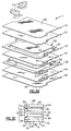
Figure 2B is an exploded perspective view of the structural member shown inFigure 2A . -
Figure 2C is a cross-sectional view of the structural member illustrated inFigure 2A . -
Figure 3A is a perspective view of a cold plate. -
Figure 3B is an exploded perspective view of the cold plate shown inFigure 3A . -
Figure 3C is a cross-sectional view of a portion of the cold plate. - A
cold plate assembly 10 is illustrated inFigure 1 . Theassembly 10 includes a first and secondcold plates structural member 16. Thestructural member 16 includes attachingfeatures 18 that are used to secure theassembly 10 to asupport 20. In one example, the attachingfeatures 18 are provided by multiple tabs having holes that are adapted to receive fastening elements, which are secured to a bracket (not shown) mounted to thesupport 20. In one instance, the planar area (which is the area that supports the device(s) 22 to be cooled) of thestructural member 16 is larger than that of eachcold plate - A
heating device 22 is supported on a surface of thecold plate 12. In one example, theheat generating device 22 is electronics and/or avionics. Theheat generating device 22 may be secured to thecold plate 12 using attachingfeatures 23, for example.Fluid ports 24 are mounted on each of thecold plates cold plates fluid system 26 that circulates the cooling fluid to theassembly 10. The cooling fluid circulates through thecold plates heat generating device 22. In one example, an internal fluid passage within thecold plate 14 overlaps the surface supporting the heat generating device 22 (see, for example, dashed lines inFigure 3A ). Although a pair ofcold plates structural member 16, it should be understood that fewer or more cold plates may be used. Moreover, one or more heat generatingdevices 22 may be mounted on each of thecold plates - An example
structural member 16 is shown in more detail inFigures 2A-2C . In one example, thestructural member 16 includes first andsecond frames cavity layers cavities layer 38 is an arrangement of fins along a first direction D1, and the second reinforcinglayer 40 is an arrangement of fins in a second direction D2 that is transverse to the first direction D1. The first andsecond frames frame passages 33 that communicate cooling fluid between the first and secondcold plates structural member 16, and for example, prevented from flowing into thecavities layers structural member 16 may contain cooling fluid during operation. By contrast, a cooling plate devotes approximately 70% of its volume to cooling fluid. For cold plate assemblies that only use a cold plate on one side of the structural member, there may be no fluid passages through thestructural member 16. - First, second and
third sheets second frames layers Figures 2A-2C . The first, second andthird sheets sheet passages 35 aligned withframe passages 33 to communicate cooling fluid between the first and secondcold plates Figure 2C , afirst braze material 42 is arranged between the first andsecond frames third sheets layers first braze material 42 is subject to a heat above the melting temperature and subsequently cooled. The first andthird sheets second surfaces cold plates Figure 2C , the first and secondcold plates second surfaces first braze material 42. - An example second
cold plate 14 is illustrated inFigures 3A-3C . Thecold plate 14 includes first andsecond end sheets first end sheet 46 includes afirst surface 66, which supports the heat generating device 22 (schematically illustrated inFigure 3A ). Thesecond end sheet 48 provides asecond surface 68, which is secured to thestructural member 16 by thefirst braze material 42. - The
cold plate 14 includes multiple layers, which include, for example, first, second andthird parting sheets second closure bars second closure bars cavities second fin structures third parting sheets sheet passage 63. The first andsecond closure bars bar passages 61 that are in fluid communication with thesheet passages 63. Thebar passages 61 and thesheet passages 63 are in fluid communication with thefluid ports 24 to supply cooling fluid to thecavities cavities second fin structures heat generating device 22 supported on thecold plate 14. Asecond braze material 64, which may be the same as thefirst braze material 42 is used to secure the layers of thecold plate 14 to one another. - During manufacturing, the layers of the
cold plates structural members 16 are arranged on top of one another, with the braze material between the layers. In one example, the layers are constructed from an aluminum, such as 3004 and/or 6951, and the braze material is CT-23 or a Multiclad alloy with a normal thickness of 0.016 inches (0.4 mm). The first and secondcold plates structural members 16 may be arranged in a fixture with one another and heated to the melting temperature of the braze material to simultaneously secure the layers of the first and secondcold plate structural members 16 to one another and the first and secondcold plates structural members 16 while applying a load to the first and secondcold plates structural members 16. In this manner, an integral; monolithiccold plate assembly 10 is formed simultaneously. - Although an example embodiment has been disclosed, a worker of ordinary skill in this art would recognize that certain modifications would come within the scope of the claims. For that reason, the following claims should be studied to determine their true scope and content.
Claims (15)
- A cold plate assembly (10) comprising:a cold plate (12,16) having a generally planar member providing a support surface (44) configured to support a heat generating device (22); anda structural member (16) providing attaching features (18) configured to secure the cold plate assembly to a support (20), the cold plate being secured to the structural member by a braze material.
- The cold plate assembly according to claim 1, wherein the cold plate provides an internal fluid passage that is in an overlapping relationship with the support surface.
- The cold plate assembly according to claim 2, wherein the fluid passage extends substantially throughout the cold plate interiorly of the support surface.
- The cold plate assembly according to claim 2 or 3, wherein the cold plate includes first and second sheets (32,34,36) with the fluid passage arranged between the first and second sheets, one of the sheets providing the support surface and the other of the sheets secured to the structural member.
- The cold plate assembly according to any preceding claim, wherein the attaching features include tabs with holes configured to be removably secured to the support.
- The cold plate assembly according to any preceding claim, comprising a fluid port (24) secured to the cold plate.
- The cold plate assembly according to any preceding claim, wherein the structural member includes a frame (28;30) providing a cavity (29,31), and a reinforcing layer (38;40) disposed within the cavity and secured to adjacent sheets.
- The cold plate assembly according to claim 7, wherein the reinforcement layer includes an arrangement of fins, preferably wherein the structural member includes multiple layers of fins arranged in transverse relationship relative to one another.
- The cold plate assembly according to claim 7 or 8, wherein the cavity extends across a substantial portion of the structural member and configured to be substantially free of fluid during an operating condition.
- A method of manufacturing a cold plate assembly (10) comprising:arranging multiple sheets (32;34;36) with a first braze material (42) provided between the sheets, one of the multiple sheets providing an external support surface (44) configured to support a heat generating device (22), the multiple sheets providing an internal fluid passage arranged to overlap the support surface, the multiple sheets comprising a cold plate;arranging at least one structural member (16) adjacent to the cold plate with a second braze material (64) provided between the cold plate and the structural member, the structural member including attaching features configured to secure the cold plate assembly to a support; andheating the first and second braze materials to mechanically join the multiple sheets to one another and the cold plate to the structural member.
- The method according to claim 10, comprising the step of simultaneously heating the first and second braze materials.
- The method according to claim 11, comprising the step of loading the cold plate and structural member together during the heating step.
- The method according to claim 10, wherein the structural member is configured to be substantially free of fluid passages.
- The method according to claim 13, wherein the second arranging step includes providing a frame (28,30) with a cavity (29,31) within which a fin layer is disposed.
- The method according to claim 13 or 14, wherein a fluid passage is disposed through the frame outside of the cavity and in fluid communication with the cold plates.
Applications Claiming Priority (1)
| Application Number | Priority Date | Filing Date | Title |
|---|---|---|---|
| US12/748,490 US8522861B2 (en) | 2010-03-29 | 2010-03-29 | Integral cold plate and structural member |
Publications (3)
| Publication Number | Publication Date |
|---|---|
| EP2372759A2 true EP2372759A2 (en) | 2011-10-05 |
| EP2372759A3 EP2372759A3 (en) | 2012-12-26 |
| EP2372759B1 EP2372759B1 (en) | 2016-10-26 |
Family
ID=44343134
Family Applications (1)
| Application Number | Title | Priority Date | Filing Date |
|---|---|---|---|
| EP11250263.8A Active EP2372759B1 (en) | 2010-03-29 | 2011-03-07 | Integral cold plate and structural member |
Country Status (4)
| Country | Link |
|---|---|
| US (1) | US8522861B2 (en) |
| EP (1) | EP2372759B1 (en) |
| JP (1) | JP5192560B2 (en) |
| CN (1) | CN102209456A (en) |
Cited By (1)
| Publication number | Priority date | Publication date | Assignee | Title |
|---|---|---|---|---|
| EP2672512A3 (en) * | 2012-06-07 | 2017-04-05 | Hamilton Sundstrand Space Systems International, Inc. | Cold plate assembly incorporating thermal heat spreader |
Families Citing this family (16)
| Publication number | Priority date | Publication date | Assignee | Title |
|---|---|---|---|---|
| WO2012153414A1 (en) * | 2011-05-12 | 2012-11-15 | トヨタ自動車株式会社 | Cooler and manufacturing method for cooler |
| US8804337B2 (en) * | 2012-03-26 | 2014-08-12 | Hamilton Sundstrand Space Systems International, Inc. | Structural assembly for cold plate cooling |
| US10871334B2 (en) * | 2013-07-03 | 2020-12-22 | Hamilton Sundstrand Corporation | Heat exchangers with multi-layer structures |
| US10161690B2 (en) * | 2014-09-22 | 2018-12-25 | Hamilton Sundstrand Space Systems International, Inc. | Multi-layer heat exchanger and method of distributing flow within a fluid layer of a multi-layer heat exchanger |
| FR3030708B1 (en) | 2014-12-22 | 2018-02-16 | Airbus Operations Sas | COLD PLATE, IN PARTICULAR A STRUCTURAL PART OF A HEAT-GENERATING COMPONENT EQUIPMENT |
| US10295229B2 (en) | 2015-09-18 | 2019-05-21 | Hamilton Sundstrand Corporation | Thermoelectric cooling system |
| US10682734B2 (en) * | 2016-06-08 | 2020-06-16 | Raytheon Company | Internal cavity support methodology for ultrasonic additive manufacturing |
| GB2552801B (en) * | 2016-08-10 | 2021-04-07 | Hs Marston Aerospace Ltd | Heat exchanger device |
| KR102737918B1 (en) * | 2017-02-28 | 2024-12-05 | 한온시스템 주식회사 | Cold Plate |
| JP6663899B2 (en) * | 2017-11-29 | 2020-03-13 | 本田技研工業株式会社 | Cooling system |
| US10978313B2 (en) | 2018-02-20 | 2021-04-13 | International Business Machines Corporation | Fixture facilitating heat sink fabrication |
| JP7236845B2 (en) * | 2018-11-15 | 2023-03-10 | 株式会社Kelk | Temperature controller |
| US20200166293A1 (en) * | 2018-11-27 | 2020-05-28 | Hamilton Sundstrand Corporation | Weaved cross-flow heat exchanger and method of forming a heat exchanger |
| US11305373B2 (en) | 2019-10-30 | 2022-04-19 | Raytheon Company | Ultrasonic additively manufactured coldplates on heat spreaders |
| EP4741753A2 (en) * | 2024-01-10 | 2026-05-13 | Ovh | Cooling block for cooling a heat-generating electronic component |
| US20260113871A1 (en) * | 2024-10-21 | 2026-04-23 | Advanced Energy Industries, Inc. | Cold plate with plastic body |
Family Cites Families (34)
| Publication number | Priority date | Publication date | Assignee | Title |
|---|---|---|---|---|
| US1571929A (en) * | 1922-05-18 | 1926-02-09 | Wilhelm B Bronander | Die holder |
| US1847573A (en) * | 1930-03-12 | 1932-03-01 | Commercial Iron Works | Platen for presses with heating coils |
| US3542636A (en) * | 1965-07-28 | 1970-11-24 | Kurt Wandel | Corrugated board |
| US3788393A (en) * | 1972-05-01 | 1974-01-29 | Us Navy | Heat exchange system |
| US4478277A (en) * | 1982-06-28 | 1984-10-23 | The Trane Company | Heat exchanger having uniform surface temperature and improved structural strength |
| US4941530A (en) * | 1989-01-13 | 1990-07-17 | Sundstrand Corporation | Enhanced air fin cooling arrangement for a hermetically sealed modular electronic cold plate utilizing reflux cooling |
| US5088005A (en) * | 1990-05-08 | 1992-02-11 | Sundstrand Corporation | Cold plate for cooling electronics |
| US5269372A (en) * | 1992-12-21 | 1993-12-14 | International Business Machines Corporation | Intersecting flow network for a cold plate cooling system |
| US5772111A (en) * | 1996-03-12 | 1998-06-30 | Kirsch; John M. | Container structure |
| US5740015A (en) * | 1996-05-02 | 1998-04-14 | Chrysler Corporation | Heat exchanger |
| US6191945B1 (en) * | 1997-07-30 | 2001-02-20 | Hewlett-Packard Company | Cold plate arrangement for cooling processor and companion voltage regulator |
| US6167952B1 (en) * | 1998-03-03 | 2001-01-02 | Hamilton Sundstrand Corporation | Cooling apparatus and method of assembling same |
| FR2782378B1 (en) * | 1998-08-14 | 2000-11-10 | Snecma | STRUCTURAL PART COMPRISING A PART OF THERMOSTRUCTURAL COMPOSITE MATERIAL COOLED BY FLUID CIRCULATION |
| US6213195B1 (en) * | 1998-12-23 | 2001-04-10 | Hamilton Sundstrand Corporation | Modular coolant manifold for use with power electronics devices having integrated coolers |
| US6130818A (en) * | 1999-05-27 | 2000-10-10 | Hamilton Sundstrand Corporation | Electronic assembly with fault tolerant cooling |
| US7302998B2 (en) * | 2000-06-08 | 2007-12-04 | Mikros Manufacturing, Inc. | Normal-flow heat exchanger |
| US7011142B2 (en) * | 2000-12-21 | 2006-03-14 | Dana Canada Corporation | Finned plate heat exchanger |
| CA2372399C (en) * | 2002-02-19 | 2010-10-26 | Long Manufacturing Ltd. | Low profile finned heat exchanger |
| DE10207873A1 (en) * | 2002-02-23 | 2003-09-04 | Modine Mfg Co | Cooling device for electronic or electrical components in motor vehicle, has container adjoining cooling fluid flow channel for receiving heat lost from components |
| US6942019B2 (en) * | 2002-03-25 | 2005-09-13 | Ltx Corporation | Apparatus and method for circuit board liquid cooling |
| US8087452B2 (en) * | 2002-04-11 | 2012-01-03 | Lytron, Inc. | Contact cooling device |
| FR2861894B1 (en) * | 2003-10-31 | 2008-01-18 | Valeo Equip Electr Moteur | DEVICE FOR COOLING A POWER ELECTRONIC |
| DE602004004083T2 (en) * | 2004-05-06 | 2007-11-15 | Movi Alluminium S.R.L. | heat exchangers |
| US7193850B2 (en) * | 2004-08-31 | 2007-03-20 | Hamilton Sundstrand Corporation | Integrated heat removal and vibration damping for avionic equipment |
| US7521789B1 (en) * | 2004-12-18 | 2009-04-21 | Rinehart Motion Systems, Llc | Electrical assembly having heat sink protrusions |
| US7201217B2 (en) * | 2005-05-24 | 2007-04-10 | Raytheon Company | Cold plate assembly |
| JP2006332393A (en) | 2005-05-27 | 2006-12-07 | T Rad Co Ltd | Water-cooled heat sink |
| DE102005034998B4 (en) * | 2005-07-27 | 2016-06-23 | Behr Industry Gmbh & Co. Kg | Method for producing a device for cooling electronic components and device for cooling electronic components |
| US7272006B2 (en) * | 2005-09-30 | 2007-09-18 | Intel Corporation | IC coolant microchannel assembly with integrated attachment hardware |
| US7272005B2 (en) * | 2005-11-30 | 2007-09-18 | International Business Machines Corporation | Multi-element heat exchange assemblies and methods of fabrication for a cooling system |
| CN100584169C (en) * | 2006-04-21 | 2010-01-20 | 富准精密工业(深圳)有限公司 | Liquid cooling device |
| US20100218923A1 (en) * | 2006-08-16 | 2010-09-02 | Kang Chang-Hee | Cooling / heating panel |
| JP2008171840A (en) | 2007-01-05 | 2008-07-24 | T Rad Co Ltd | Liquid-cooled heat sink and design method thereof |
| JP4967988B2 (en) * | 2007-10-25 | 2012-07-04 | 株式会社豊田自動織機 | Semiconductor cooling device |
-
2010
- 2010-03-29 US US12/748,490 patent/US8522861B2/en active Active
-
2011
- 2011-03-07 EP EP11250263.8A patent/EP2372759B1/en active Active
- 2011-03-17 JP JP2011058657A patent/JP5192560B2/en not_active Expired - Fee Related
- 2011-03-29 CN CN2011100764859A patent/CN102209456A/en active Pending
Non-Patent Citations (1)
| Title |
|---|
| None |
Cited By (1)
| Publication number | Priority date | Publication date | Assignee | Title |
|---|---|---|---|---|
| EP2672512A3 (en) * | 2012-06-07 | 2017-04-05 | Hamilton Sundstrand Space Systems International, Inc. | Cold plate assembly incorporating thermal heat spreader |
Also Published As
| Publication number | Publication date |
|---|---|
| JP5192560B2 (en) | 2013-05-08 |
| US8522861B2 (en) | 2013-09-03 |
| CN102209456A (en) | 2011-10-05 |
| EP2372759A3 (en) | 2012-12-26 |
| EP2372759B1 (en) | 2016-10-26 |
| JP2011211193A (en) | 2011-10-20 |
| US20110232863A1 (en) | 2011-09-29 |
Similar Documents
| Publication | Publication Date | Title |
|---|---|---|
| EP2372759B1 (en) | Integral cold plate and structural member | |
| EP2372761B1 (en) | Cold plate with integral structural fluid port | |
| US8991478B2 (en) | Compact two sided cold plate with transfer tubes | |
| EP3759761B1 (en) | Cooling system integrated with vehicle battery tray | |
| US9929389B2 (en) | Battery device and method of production thereof | |
| US12308408B2 (en) | Battery cooling plate | |
| US8931546B2 (en) | Compact two sided cold plate with threaded inserts | |
| US20110232882A1 (en) | Compact cold plate configuration utilizing ramped closure bars | |
| CN103219558A (en) | Power battery temperature adjusting device and making method thereof | |
| JPH0763487A (en) | Plate type heat pipe | |
| EP2660155B1 (en) | Apparatus and method for mounting heat pipes to panels | |
| EP3298339B1 (en) | Heat exchanger and heat exchanger tank | |
| US11982492B2 (en) | Heat exchanger, tank for heat exchanger, and method of making the same | |
| EP2672512B1 (en) | Cold plate assembly incorporating thermal heat spreader | |
| WO2024054861A1 (en) | Battery modules with casted module enclosures and battery packs with safety features | |
| US20110232866A1 (en) | Integral cold plate and honeycomb facesheet assembly | |
| FI121266B (en) | A method for manufacturing a load-bearing laminated glass element and a load-bearing laminated glass element | |
| US20180124951A1 (en) | Water wall | |
| JP2005190989A (en) | Heating apparatus and heating method |
Legal Events
| Date | Code | Title | Description |
|---|---|---|---|
| PUAI | Public reference made under article 153(3) epc to a published international application that has entered the european phase |
Free format text: ORIGINAL CODE: 0009012 |
|
| AK | Designated contracting states |
Kind code of ref document: A2 Designated state(s): AL AT BE BG CH CY CZ DE DK EE ES FI FR GB GR HR HU IE IS IT LI LT LU LV MC MK MT NL NO PL PT RO RS SE SI SK SM TR |
|
| AX | Request for extension of the european patent |
Extension state: BA ME |
|
| PUAL | Search report despatched |
Free format text: ORIGINAL CODE: 0009013 |
|
| AK | Designated contracting states |
Kind code of ref document: A3 Designated state(s): AL AT BE BG CH CY CZ DE DK EE ES FI FR GB GR HR HU IE IS IT LI LT LU LV MC MK MT NL NO PL PT RO RS SE SI SK SM TR |
|
| AX | Request for extension of the european patent |
Extension state: BA ME |
|
| RIC1 | Information provided on ipc code assigned before grant |
Ipc: H01L 23/473 20060101AFI20121122BHEP |
|
| RAP1 | Party data changed (applicant data changed or rights of an application transferred) |
Owner name: HAMILTON SUNDSTRAND SPACE SYSTEMS INTERNATIONAL, I |
|
| 17P | Request for examination filed |
Effective date: 20130626 |
|
| RBV | Designated contracting states (corrected) |
Designated state(s): AL AT BE BG CH CY CZ DE DK EE ES FI FR GB GR HR HU IE IS IT LI LT LU LV MC MK MT NL NO PL PT RO RS SE SI SK SM TR |
|
| GRAP | Despatch of communication of intention to grant a patent |
Free format text: ORIGINAL CODE: EPIDOSNIGR1 |
|
| INTG | Intention to grant announced |
Effective date: 20160520 |
|
| GRAS | Grant fee paid |
Free format text: ORIGINAL CODE: EPIDOSNIGR3 |
|
| GRAA | (expected) grant |
Free format text: ORIGINAL CODE: 0009210 |
|
| AK | Designated contracting states |
Kind code of ref document: B1 Designated state(s): AL AT BE BG CH CY CZ DE DK EE ES FI FR GB GR HR HU IE IS IT LI LT LU LV MC MK MT NL NO PL PT RO RS SE SI SK SM TR |
|
| REG | Reference to a national code |
Ref country code: GB Ref legal event code: FG4D |
|
| REG | Reference to a national code |
Ref country code: CH Ref legal event code: EP |
|
| REG | Reference to a national code |
Ref country code: AT Ref legal event code: REF Ref document number: 840557 Country of ref document: AT Kind code of ref document: T Effective date: 20161115 |
|
| REG | Reference to a national code |
Ref country code: IE Ref legal event code: FG4D |
|
| REG | Reference to a national code |
Ref country code: DE Ref legal event code: R096 Ref document number: 602011031631 Country of ref document: DE |
|
| REG | Reference to a national code |
Ref country code: FR Ref legal event code: PLFP Year of fee payment: 7 |
|
| REG | Reference to a national code |
Ref country code: LT Ref legal event code: MG4D |
|
| PG25 | Lapsed in a contracting state [announced via postgrant information from national office to epo] |
Ref country code: LV Free format text: LAPSE BECAUSE OF FAILURE TO SUBMIT A TRANSLATION OF THE DESCRIPTION OR TO PAY THE FEE WITHIN THE PRESCRIBED TIME-LIMIT Effective date: 20161026 |
|
| REG | Reference to a national code |
Ref country code: NL Ref legal event code: MP Effective date: 20161026 |
|
| REG | Reference to a national code |
Ref country code: AT Ref legal event code: MK05 Ref document number: 840557 Country of ref document: AT Kind code of ref document: T Effective date: 20161026 |
|
| PG25 | Lapsed in a contracting state [announced via postgrant information from national office to epo] |
Ref country code: LT Free format text: LAPSE BECAUSE OF FAILURE TO SUBMIT A TRANSLATION OF THE DESCRIPTION OR TO PAY THE FEE WITHIN THE PRESCRIBED TIME-LIMIT Effective date: 20161026 Ref country code: GR Free format text: LAPSE BECAUSE OF FAILURE TO SUBMIT A TRANSLATION OF THE DESCRIPTION OR TO PAY THE FEE WITHIN THE PRESCRIBED TIME-LIMIT Effective date: 20170127 Ref country code: NO Free format text: LAPSE BECAUSE OF FAILURE TO SUBMIT A TRANSLATION OF THE DESCRIPTION OR TO PAY THE FEE WITHIN THE PRESCRIBED TIME-LIMIT Effective date: 20170126 Ref country code: SE Free format text: LAPSE BECAUSE OF FAILURE TO SUBMIT A TRANSLATION OF THE DESCRIPTION OR TO PAY THE FEE WITHIN THE PRESCRIBED TIME-LIMIT Effective date: 20161026 |
|
| PG25 | Lapsed in a contracting state [announced via postgrant information from national office to epo] |
Ref country code: PT Free format text: LAPSE BECAUSE OF FAILURE TO SUBMIT A TRANSLATION OF THE DESCRIPTION OR TO PAY THE FEE WITHIN THE PRESCRIBED TIME-LIMIT Effective date: 20170227 Ref country code: HR Free format text: LAPSE BECAUSE OF FAILURE TO SUBMIT A TRANSLATION OF THE DESCRIPTION OR TO PAY THE FEE WITHIN THE PRESCRIBED TIME-LIMIT Effective date: 20161026 Ref country code: FI Free format text: LAPSE BECAUSE OF FAILURE TO SUBMIT A TRANSLATION OF THE DESCRIPTION OR TO PAY THE FEE WITHIN THE PRESCRIBED TIME-LIMIT Effective date: 20161026 Ref country code: ES Free format text: LAPSE BECAUSE OF FAILURE TO SUBMIT A TRANSLATION OF THE DESCRIPTION OR TO PAY THE FEE WITHIN THE PRESCRIBED TIME-LIMIT Effective date: 20161026 Ref country code: PL Free format text: LAPSE BECAUSE OF FAILURE TO SUBMIT A TRANSLATION OF THE DESCRIPTION OR TO PAY THE FEE WITHIN THE PRESCRIBED TIME-LIMIT Effective date: 20161026 Ref country code: AT Free format text: LAPSE BECAUSE OF FAILURE TO SUBMIT A TRANSLATION OF THE DESCRIPTION OR TO PAY THE FEE WITHIN THE PRESCRIBED TIME-LIMIT Effective date: 20161026 Ref country code: BE Free format text: LAPSE BECAUSE OF FAILURE TO SUBMIT A TRANSLATION OF THE DESCRIPTION OR TO PAY THE FEE WITHIN THE PRESCRIBED TIME-LIMIT Effective date: 20161026 Ref country code: IS Free format text: LAPSE BECAUSE OF FAILURE TO SUBMIT A TRANSLATION OF THE DESCRIPTION OR TO PAY THE FEE WITHIN THE PRESCRIBED TIME-LIMIT Effective date: 20170226 Ref country code: RS Free format text: LAPSE BECAUSE OF FAILURE TO SUBMIT A TRANSLATION OF THE DESCRIPTION OR TO PAY THE FEE WITHIN THE PRESCRIBED TIME-LIMIT Effective date: 20161026 Ref country code: NL Free format text: LAPSE BECAUSE OF FAILURE TO SUBMIT A TRANSLATION OF THE DESCRIPTION OR TO PAY THE FEE WITHIN THE PRESCRIBED TIME-LIMIT Effective date: 20161026 |
|
| REG | Reference to a national code |
Ref country code: DE Ref legal event code: R097 Ref document number: 602011031631 Country of ref document: DE |
|
| PG25 | Lapsed in a contracting state [announced via postgrant information from national office to epo] |
Ref country code: RO Free format text: LAPSE BECAUSE OF FAILURE TO SUBMIT A TRANSLATION OF THE DESCRIPTION OR TO PAY THE FEE WITHIN THE PRESCRIBED TIME-LIMIT Effective date: 20161026 Ref country code: CZ Free format text: LAPSE BECAUSE OF FAILURE TO SUBMIT A TRANSLATION OF THE DESCRIPTION OR TO PAY THE FEE WITHIN THE PRESCRIBED TIME-LIMIT Effective date: 20161026 Ref country code: DK Free format text: LAPSE BECAUSE OF FAILURE TO SUBMIT A TRANSLATION OF THE DESCRIPTION OR TO PAY THE FEE WITHIN THE PRESCRIBED TIME-LIMIT Effective date: 20161026 Ref country code: SK Free format text: LAPSE BECAUSE OF FAILURE TO SUBMIT A TRANSLATION OF THE DESCRIPTION OR TO PAY THE FEE WITHIN THE PRESCRIBED TIME-LIMIT Effective date: 20161026 Ref country code: EE Free format text: LAPSE BECAUSE OF FAILURE TO SUBMIT A TRANSLATION OF THE DESCRIPTION OR TO PAY THE FEE WITHIN THE PRESCRIBED TIME-LIMIT Effective date: 20161026 |
|
| PG25 | Lapsed in a contracting state [announced via postgrant information from national office to epo] |
Ref country code: BG Free format text: LAPSE BECAUSE OF FAILURE TO SUBMIT A TRANSLATION OF THE DESCRIPTION OR TO PAY THE FEE WITHIN THE PRESCRIBED TIME-LIMIT Effective date: 20170126 Ref country code: SM Free format text: LAPSE BECAUSE OF FAILURE TO SUBMIT A TRANSLATION OF THE DESCRIPTION OR TO PAY THE FEE WITHIN THE PRESCRIBED TIME-LIMIT Effective date: 20161026 |
|
| PLBE | No opposition filed within time limit |
Free format text: ORIGINAL CODE: 0009261 |
|
| STAA | Information on the status of an ep patent application or granted ep patent |
Free format text: STATUS: NO OPPOSITION FILED WITHIN TIME LIMIT |
|
| 26N | No opposition filed |
Effective date: 20170727 |
|
| REG | Reference to a national code |
Ref country code: CH Ref legal event code: PL |
|
| PG25 | Lapsed in a contracting state [announced via postgrant information from national office to epo] |
Ref country code: MC Free format text: LAPSE BECAUSE OF FAILURE TO SUBMIT A TRANSLATION OF THE DESCRIPTION OR TO PAY THE FEE WITHIN THE PRESCRIBED TIME-LIMIT Effective date: 20161026 Ref country code: SI Free format text: LAPSE BECAUSE OF FAILURE TO SUBMIT A TRANSLATION OF THE DESCRIPTION OR TO PAY THE FEE WITHIN THE PRESCRIBED TIME-LIMIT Effective date: 20161026 |
|
| REG | Reference to a national code |
Ref country code: IE Ref legal event code: MM4A |
|
| PG25 | Lapsed in a contracting state [announced via postgrant information from national office to epo] |
Ref country code: LU Free format text: LAPSE BECAUSE OF NON-PAYMENT OF DUE FEES Effective date: 20170307 |
|
| REG | Reference to a national code |
Ref country code: FR Ref legal event code: PLFP Year of fee payment: 8 |
|
| PG25 | Lapsed in a contracting state [announced via postgrant information from national office to epo] |
Ref country code: CH Free format text: LAPSE BECAUSE OF NON-PAYMENT OF DUE FEES Effective date: 20170331 Ref country code: IE Free format text: LAPSE BECAUSE OF NON-PAYMENT OF DUE FEES Effective date: 20170307 Ref country code: LI Free format text: LAPSE BECAUSE OF NON-PAYMENT OF DUE FEES Effective date: 20170331 |
|
| PG25 | Lapsed in a contracting state [announced via postgrant information from national office to epo] |
Ref country code: MT Free format text: LAPSE BECAUSE OF NON-PAYMENT OF DUE FEES Effective date: 20170307 |
|
| PG25 | Lapsed in a contracting state [announced via postgrant information from national office to epo] |
Ref country code: HU Free format text: LAPSE BECAUSE OF FAILURE TO SUBMIT A TRANSLATION OF THE DESCRIPTION OR TO PAY THE FEE WITHIN THE PRESCRIBED TIME-LIMIT; INVALID AB INITIO Effective date: 20110307 |
|
| PG25 | Lapsed in a contracting state [announced via postgrant information from national office to epo] |
Ref country code: CY Free format text: LAPSE BECAUSE OF NON-PAYMENT OF DUE FEES Effective date: 20161026 |
|
| PG25 | Lapsed in a contracting state [announced via postgrant information from national office to epo] |
Ref country code: MK Free format text: LAPSE BECAUSE OF FAILURE TO SUBMIT A TRANSLATION OF THE DESCRIPTION OR TO PAY THE FEE WITHIN THE PRESCRIBED TIME-LIMIT Effective date: 20161026 |
|
| PG25 | Lapsed in a contracting state [announced via postgrant information from national office to epo] |
Ref country code: TR Free format text: LAPSE BECAUSE OF FAILURE TO SUBMIT A TRANSLATION OF THE DESCRIPTION OR TO PAY THE FEE WITHIN THE PRESCRIBED TIME-LIMIT Effective date: 20161026 |
|
| PG25 | Lapsed in a contracting state [announced via postgrant information from national office to epo] |
Ref country code: AL Free format text: LAPSE BECAUSE OF FAILURE TO SUBMIT A TRANSLATION OF THE DESCRIPTION OR TO PAY THE FEE WITHIN THE PRESCRIBED TIME-LIMIT Effective date: 20161026 |
|
| REG | Reference to a national code |
Ref country code: DE Ref legal event code: R082 Ref document number: 602011031631 Country of ref document: DE |
|
| REG | Reference to a national code |
Ref country code: DE Ref legal event code: R079 Ref document number: 602011031631 Country of ref document: DE Free format text: PREVIOUS MAIN CLASS: H01L0023473000 Ipc: H10W0040470000 |
|
| P01 | Opt-out of the competence of the unified patent court (upc) registered |
Free format text: CASE NUMBER: UPC_APP_0016457_2372759/2025 Effective date: 20251209 |
|
| PGFP | Annual fee paid to national office [announced via postgrant information from national office to epo] |
Ref country code: GB Payment date: 20260219 Year of fee payment: 16 |
|
| PGFP | Annual fee paid to national office [announced via postgrant information from national office to epo] |
Ref country code: DE Payment date: 20260219 Year of fee payment: 16 |
|
| PGFP | Annual fee paid to national office [announced via postgrant information from national office to epo] |
Ref country code: IT Payment date: 20260219 Year of fee payment: 16 |
|
| PGFP | Annual fee paid to national office [announced via postgrant information from national office to epo] |
Ref country code: FR Payment date: 20260219 Year of fee payment: 16 |