EP2372736A1 - Relay-end-of-service-life forecasting device and method - Google Patents
Relay-end-of-service-life forecasting device and method Download PDFInfo
- Publication number
- EP2372736A1 EP2372736A1 EP11159097A EP11159097A EP2372736A1 EP 2372736 A1 EP2372736 A1 EP 2372736A1 EP 11159097 A EP11159097 A EP 11159097A EP 11159097 A EP11159097 A EP 11159097A EP 2372736 A1 EP2372736 A1 EP 2372736A1
- Authority
- EP
- European Patent Office
- Prior art keywords
- relay
- time
- closing
- service life
- opening
- Prior art date
- Legal status (The legal status is an assumption and is not a legal conclusion. Google has not performed a legal analysis and makes no representation as to the accuracy of the status listed.)
- Withdrawn
Links
- 238000000034 method Methods 0.000 title claims description 10
- 238000005259 measurement Methods 0.000 claims description 23
- 230000000694 effects Effects 0.000 abstract description 7
- 230000007613 environmental effect Effects 0.000 abstract description 5
- 238000010586 diagram Methods 0.000 description 3
- 238000003745 diagnosis Methods 0.000 description 2
- 238000003466 welding Methods 0.000 description 2
- 230000003466 anti-cipated effect Effects 0.000 description 1
- 230000001419 dependent effect Effects 0.000 description 1
- 239000000155 melt Substances 0.000 description 1
Images
Classifications
-
- H—ELECTRICITY
- H01—ELECTRIC ELEMENTS
- H01H—ELECTRIC SWITCHES; RELAYS; SELECTORS; EMERGENCY PROTECTIVE DEVICES
- H01H47/00—Circuit arrangements not adapted to a particular application of the relay and designed to obtain desired operating characteristics or to provide energising current
- H01H47/002—Monitoring or fail-safe circuits
-
- G—PHYSICS
- G01—MEASURING; TESTING
- G01R—MEASURING ELECTRIC VARIABLES; MEASURING MAGNETIC VARIABLES
- G01R31/00—Arrangements for testing electric properties; Arrangements for locating electric faults; Arrangements for electrical testing characterised by what is being tested not provided for elsewhere
- G01R31/327—Testing of circuit interrupters, switches or circuit-breakers
- G01R31/3277—Testing of circuit interrupters, switches or circuit-breakers of low voltage devices, e.g. domestic or industrial devices, such as motor protections, relays, rotation switches
- G01R31/3278—Testing of circuit interrupters, switches or circuit-breakers of low voltage devices, e.g. domestic or industrial devices, such as motor protections, relays, rotation switches of relays, solenoids or reed switches
-
- H—ELECTRICITY
- H01—ELECTRIC ELEMENTS
- H01H—ELECTRIC SWITCHES; RELAYS; SELECTORS; EMERGENCY PROTECTIVE DEVICES
- H01H11/00—Apparatus or processes specially adapted for the manufacture of electric switches
- H01H11/0062—Testing or measuring non-electrical properties of switches, e.g. contact velocity
-
- H—ELECTRICITY
- H01—ELECTRIC ELEMENTS
- H01H—ELECTRIC SWITCHES; RELAYS; SELECTORS; EMERGENCY PROTECTIVE DEVICES
- H01H3/00—Mechanisms for operating contacts
- H01H3/001—Means for preventing or breaking contact-welding
-
- H—ELECTRICITY
- H01—ELECTRIC ELEMENTS
- H01H—ELECTRIC SWITCHES; RELAYS; SELECTORS; EMERGENCY PROTECTIVE DEVICES
- H01H71/00—Details of the protective switches or relays covered by groups H01H73/00 - H01H83/00
- H01H71/04—Means for indicating condition of the switching device
- H01H2071/044—Monitoring, detection or measuring systems to establish the end of life of the switching device, can also contain other on-line monitoring systems, e.g. for detecting mechanical failures
Definitions
- the present invention relates to an end-of-service-life forecasting device for forecasting the end of the service life of an electromagnetic relay. Further the present invention relates to a method for forecasting the end-of-service-life of a relay.
- Electromagnetic relays comprising a relay coil and a relay contact that is opened and closed through the application of an electric current to the relay coil are broadly and generally known.
- the relay contacts in such relays are switched mechanically between ON and OFF by magnetic forces generated by the coil.
- mechanical switches including this type of relay, when the contact is turned ON or OFF, an electric discharge is produced between the electrodes of the contacts, where the heat due to the electric discharge melts the surfaces of the electrodes, forming recessed and raised patterns on the surfaces.
- electromagnetic relay contact end-of-service-life forecasts are performed by comparing the number of opening/closing cycles for the contacts that is the durability reported by the manufacturer to the actual number of opening/closing cycles, or through calculations based on the electric current flowing in the relay (See, for example, Japanese Unexamined Patent Application Publication H05-266290 ("JP '290”)).
- the object of the invention in the present application is to provide a relay end-of-service-life forecasting device able to forecast the end of the service life of an electromagnetic relay accurately.
- the relay end-of-service-life forecasting device including a relay having a relay coil and a relay contact that is opened and closed by the application of an electric current to the relay coil; a controlling portion for controlling the opening/closing of the relay through controlling the application of the electric current to the relay coil; a detecting portion for detecting the actual opening/closing of the relay; a measuring portion for measuring the time from a point in time wherein the application of the electric current to the relay coil is started by the controlling portion, or from the point in time that the application of the electric current to the relay coil is stopped by the controlling portion, until the point in time that the opening/closing of the relay is detected by the detecting portion; and a diagnosing portion for diagnosing the end of the service life of the relay based on the measurement results by the measuring portion.
- the diagnosing portion may diagnose the end of the relay service life of the relay based on a comparison of the amount of change in the opening/closing count and the amount of change in the measurement result, from among the measurement results by the measuring portion.
- the diagnosing portion may diagnose the end of the relay service life through comparing the value of the measurement result to a predetermined threshold value, from among the measurement results by the measuring portion.
- the diagnosing of the end of the service life of the relay based on the time from a point in time wherein the application of the electric current to the relay coil is started by the controlling portion, or from the point in time that the application of the electric current to the relay coil is stopped by the controlling portion, until the point in time that the opening/closing of the relay is detected by the detecting portion makes it possible to forecast the end of the service life of the electromagnetic relay accurately, without a significant drop in the forecasting accuracy due to the effects of the load conditions or the environmental conditions.
- Forecasting the end of the service life of a relay more accurately due to the effects of the load conditions and the environmental conditions can occur through diagnosing the end of service life of the relay based on the time, until the point in time that the actual opening or closing of the relay is detected, from the point in time of the application of the power to the relay or the point in time of the end of application of power to the relay coil by the controlling portion. Forecasting the end of the service life of the relay based on time, increases accuracy because time is a value that is not affected by the external environment. Additionally, because the end of the service life is forecasted based on the actual opening/closing of the relay, not only is it possible to detect immediately a fault in the relay, but it is also possible to eliminate the effects due to individual differences.
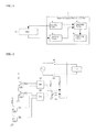
- the end-of-service-life forecasting device 1 in an example includes a controlling portion 2 for controlling the opening/closing of a relay 10; a detecting portion 3 for detecting the opening/closing of the contacts of the relay 10; a measuring portion 4 for measuring the time required to open/close the relay 10; and a diagnosing portion 5 for diagnosing the end of the service life of the relay 10 based on the measurement result by the measuring portion 4.
- the controlling portion 2 is structured from an electric circuit for controlling the opening/closing of the relay 10. This controlling portion 2 provides notification to the measuring portion 4 when a control signal that is an instruction for opening/closing is outputted to the relay 10.
- the detecting portion 3 is structured from a detecting device that detects the actual opening/closing of the relay 10. This detecting portion 3 provides notification to the measuring portion 4 when opening/closing of the relay 10 is detected.
- the measuring portion 4 is structured from a measuring device that measures the time from the point in time wherein the control signal is outputted from the controlling portion 2 to the relay 10, or the point in time wherein the output (an electric current) of the control signal from the controlling portion 2 to the relay 10 is stopped, until the point in time wherein the relay 10 actually opens or closes, based on the control signal, according to the detecting portion 3.
- the measuring portion 4 measures the response time (hereinafter termed the "operating time”) from the point in time wherein the control signal instructing the contacts to close is outputted from the controlling portion 2 to the relay 10, that is, from the point in time wherein the application of the electric current to the relay 10 is started until the point in time at which the actual closing of the relay 10 is detected by the detecting portion 3, and measures the response time (hereinafter termed the “return time”) from the point in time wherein the output of the control signal instructing the contacts to open is outputted from the controlling portion 2 to the relay 10, that is, from the point in time wherein the application of the electric current to the relay 10 is stopped, until the point in time wherein the actual opening of the relay 10 is detected by the detecting portion 3.
- These measurement results are outputted to the diagnosing portion 5.
- the diagnosing portion 5 diagnoses the end of the service life of the relay 10 based on the operating time and the return time measured by the measuring portion 4. A correlation is observed between the operating time and return time and the opening/closing cycle count for the electromagnetic relay. This correlation will be explained in reference to FIG. 2 through FIG. 5 .
- Electromagnetic relay durability testing was performed on the electric circuit as illustrated in FIG. 2 .
- an Omron LY2 (24 V DC) electromagnetic relay was used as the electromagnetic relay for structuring the switches 101 and 102, where a photocoupler circuit 103 is connected to the contacts of the relay, and opening/closing instructions were outputted to the aforementioned relays, and the operating time and return time thereof were measured by a CPU 104 and a CPU 105.
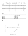
- the results of performing these types of measurements on samples 1 through 4 are presented in FIG. 3 and FIG. 4 .
- the operating time and the return time increased in accordance with the number of opening/closing cycles, and increased further immediately prior to the occurrence of the point in time wherein the electromagnetic relay welded. That is, as illustrated in FIG. 5 , the operating time and return time, and the number of opening/closing cycles, formed a second-order curve. Note that in FIG. 3 , "after testing" is at the number of cycles at which that there was welding of contacts, where the values in this column are values that were measured in the same manner after separating the contacts after they had been welded.
- the diagnosing portion 5 diagnoses the end of the service life of the relay 10 based on a comparison of the amount of change in the return time and the operating time and the amount of change in the number of opening/closing cycles. For example, as indicated by the code "a" in FIG. 5 , when the value for the slope of the tangent of the curve of the return time or the operating time exceeds a specific value, then the diagnosis is that the end of the service life of the relay 10 is approaching. This specific value may be set in advance based on measurement results for samples, as described above. Note that the diagnosing results may be displayed on a display, or the like, or may be outputted from a speaker.
- the present example makes it possible to forecast the end of the service life of the relay 10 more accurately, by performing the diagnosis of the end of the service life of the relay 10 based on the time from the point in time of the beginning of the application of the electric current to the relay 10 or the point in time of the end of the application of the electric current to the relay coil by the controlling portion 2 and the point in time at which the actual opening/closing of the relay 10 is detected, without any significant drop in the forecasting accuracy due to the effects of the load conditions and the environmental conditions. That is, it is possible to forecast the end of the service life of the relay 10 more accurately by forecasting the end of the service life of the relay 10 based on time, which is a value that is not affected by the external environment.
- the end of the service life is forecasted based on the actual opening/closing of the relay 10, not only is it possible to detect immediately a fault in the relay 10, but it is also possible to eliminate the effects due to individual differences, making it possible to forecast the end of the service life of the relay 10 more accurately.
- the end of the service life of an electromagnetic relay was diagnosed based on the value of the slope of the tangent of the curve for the return time or the operating time in the diagnosing portion 5.
- a specific threshold value may be provided for the return time or the operating time, as indicated by code "b" in FIG. 5 , and the diagnosing of the approaching end of service life may be made when that threshold value is surpassed. In this case, the number of opening/closing cycles need not be counted.
- the measuring portion 4 need not necessarily perform the measurement of the return time and the operating time with each cycle.
- the measurement may be performed at each specific number of cycles, such as with each thousandth opening/closing cycle of the relay 10.
- the present invention can be applied to various types of devices equipped with electromagnetic relays.
Abstract
Forecasting the end of the service life of a relay more accurately due to the effects of the load conditions and the environmental conditions can occur through diagnosing the end of service life of the relay based on the time, until the point in time that the actual opening or closing of the relay is detected, from the point in time of the application of the power to the relay or the point in time of the end of application of power to the relay coil by the controlling portion. Forecasting the end of the service life of the relay based on time, increases accuracy because time is a value that is not affected by the external environment. Additionally, because the end of the service life is forecasted based on the actual opening/closing of the relay, not only is it possible to detect immediately a fault in the relay, but it is also possible to eliminate the effects due to individual differences.
Description
- The present application claims priority to Japanese Patent Application No.
2010-077247, filed March 30, 2010 - The present invention relates to an end-of-service-life forecasting device for forecasting the end of the service life of an electromagnetic relay. Further the present invention relates to a method for forecasting the end-of-service-life of a relay.
- Electromagnetic relays comprising a relay coil and a relay contact that is opened and closed through the application of an electric current to the relay coil are broadly and generally known. The relay contacts in such relays are switched mechanically between ON and OFF by magnetic forces generated by the coil. In mechanical switches, including this type of relay, when the contact is turned ON or OFF, an electric discharge is produced between the electrodes of the contacts, where the heat due to the electric discharge melts the surfaces of the electrodes, forming recessed and raised patterns on the surfaces. In the electrodes wherein uneven surfaces are formed, the electric discharges tend to initiate at the recessed/raised surfaces, and thus the recessed and raised portions propagate as the relay contacts are switched repetitively between ON and OFF multiple times, ultimately causing the electrodes, wherein the surfaces have been melted by the heat, to weld together, causing the contacts to become stuck perpetually in the ON state. End-of-service-life forecasts are performed in order to evaluate whether a relay that is currently in use can be evaluated as being safe from producing a welded contact, or whether it is better to switch the relay due to the likelihood of the occurrence of welding. For example, electromagnetic relay contact end-of-service-life forecasts are performed by comparing the number of opening/closing cycles for the contacts that is the durability reported by the manufacturer to the actual number of opening/closing cycles, or through calculations based on the electric current flowing in the relay (See, for example, Japanese Unexamined Patent Application Publication
H05-266290 - However, it is difficult to forecast the end of the service life of the electromagnetic relay accurately using the methods set forth above. For example, in the method wherein the number of opening/closing cycles of the contacts that is the durability reported by the manufacturer is compared to the actual number of opening/closing cycles for the contacts, there are cases wherein the loading conditions (the resistance, voltage, electric current, and the like, in the circuit that includes the electromagnetic relay) may be different from measurement to measurement, causing large discrepancies in the respective number of opening/closing cycles prior to failure, and thus the accuracy of the forecast will be less the greater the difference between the actual limit cycle count in the actual equipment and the value reported by the manufacturer. Moreover, in the method of calculating the service life by substituting load conditions, such as the electric current, into a specific end-of-service-life forecasting equation, as disclosed in JP '290, there will be cases wherein the load conditions anticipated in advance to not match the loads produced in actual use, due to, for example, the resistance values within the electromagnetic relays varying due to environmental factors such as the mechanism, the ambient gas, noise, and the like, and the accuracy of the forecast will suffer in such cases.
- Given this, the object of the invention in the present application is to provide a relay end-of-service-life forecasting device able to forecast the end of the service life of an electromagnetic relay accurately.
- In order to solve the problem set forth above, the relay end-of-service-life forecasting device including a relay having a relay coil and a relay contact that is opened and closed by the application of an electric current to the relay coil; a controlling portion for controlling the opening/closing of the relay through controlling the application of the electric current to the relay coil; a detecting portion for detecting the actual opening/closing of the relay; a measuring portion for measuring the time from a point in time wherein the application of the electric current to the relay coil is started by the controlling portion, or from the point in time that the application of the electric current to the relay coil is stopped by the controlling portion, until the point in time that the opening/closing of the relay is detected by the detecting portion; and a diagnosing portion for diagnosing the end of the service life of the relay based on the measurement results by the measuring portion.
- In the relay end-of-service-life forecasting device as set forth above, the diagnosing portion may diagnose the end of the relay service life of the relay based on a comparison of the amount of change in the opening/closing count and the amount of change in the measurement result, from among the measurement results by the measuring portion.
- Additionally, in the relay end-of-service-life forecasting device set forth above, the diagnosing portion may diagnose the end of the relay service life through comparing the value of the measurement result to a predetermined threshold value, from among the measurement results by the measuring portion.
- Additionally, a method for forecasting the end-of-service-life of a relay according to
claim 4 is provided. Further advantages, features, aspects and details are evident from the dependent claims, the description and the drawings. - Given the present invention, the diagnosing of the end of the service life of the relay based on the time from a point in time wherein the application of the electric current to the relay coil is started by the controlling portion, or from the point in time that the application of the electric current to the relay coil is stopped by the controlling portion, until the point in time that the opening/closing of the relay is detected by the detecting portion makes it possible to forecast the end of the service life of the electromagnetic relay accurately, without a significant drop in the forecasting accuracy due to the effects of the load conditions or the environmental conditions.
- Forecasting the end of the service life of a relay more accurately due to the effects of the load conditions and the environmental conditions can occur through diagnosing the end of service life of the relay based on the time, until the point in time that the actual opening or closing of the relay is detected, from the point in time of the application of the power to the relay or the point in time of the end of application of power to the relay coil by the controlling portion. Forecasting the end of the service life of the relay based on time, increases accuracy because time is a value that is not affected by the external environment. Additionally, because the end of the service life is forecasted based on the actual opening/closing of the relay, not only is it possible to detect immediately a fault in the relay, but it is also possible to eliminate the effects due to individual differences.
-
-
FIG. 1 is a diagram illustrating schematically the structure of end-of-service-life forecasting device according to the present invention. -
FIG. 2 is a diagram illustrating an example of an electric circuit used in examining the electromagnetic relay. -
FIG. 3 is an experimental result in the electric circuit inFIG. 2 . -
FIG. 4 is an experimental result in the electric circuit inFIG. 2 . -
FIG. 5 is a diagram illustrating the relationship between the operating time and return time and the opening/closing count. - An example of the present invention will be described in detail below in reference to the drawings.
- As illustrated in
FIG. 1 , the end-of-service-life forecasting device 1 in an example includes a controllingportion 2 for controlling the opening/closing of a relay 10; a detectingportion 3 for detecting the opening/closing of the contacts of the relay 10; ameasuring portion 4 for measuring the time required to open/close the relay 10; and a diagnosing portion 5 for diagnosing the end of the service life of the relay 10 based on the measurement result by themeasuring portion 4. - The controlling
portion 2 is structured from an electric circuit for controlling the opening/closing of the relay 10. This controllingportion 2 provides notification to themeasuring portion 4 when a control signal that is an instruction for opening/closing is outputted to the relay 10. - The detecting
portion 3 is structured from a detecting device that detects the actual opening/closing of the relay 10. This detectingportion 3 provides notification to themeasuring portion 4 when opening/closing of the relay 10 is detected. - The
measuring portion 4 is structured from a measuring device that measures the time from the point in time wherein the control signal is outputted from the controllingportion 2 to the relay 10, or the point in time wherein the output (an electric current) of the control signal from the controllingportion 2 to the relay 10 is stopped, until the point in time wherein the relay 10 actually opens or closes, based on the control signal, according to the detectingportion 3. Specifically, themeasuring portion 4 measures the response time (hereinafter termed the "operating time") from the point in time wherein the control signal instructing the contacts to close is outputted from the controllingportion 2 to the relay 10, that is, from the point in time wherein the application of the electric current to the relay 10 is started until the point in time at which the actual closing of the relay 10 is detected by the detectingportion 3, and measures the response time (hereinafter termed the "return time") from the point in time wherein the output of the control signal instructing the contacts to open is outputted from the controllingportion 2 to the relay 10, that is, from the point in time wherein the application of the electric current to the relay 10 is stopped, until the point in time wherein the actual opening of the relay 10 is detected by the detectingportion 3. These measurement results are outputted to the diagnosing portion 5. - The diagnosing portion 5 diagnoses the end of the service life of the relay 10 based on the operating time and the return time measured by the
measuring portion 4. A correlation is observed between the operating time and return time and the opening/closing cycle count for the electromagnetic relay. This correlation will be explained in reference toFIG. 2 through FIG. 5 . - Electromagnetic relay durability testing was performed on the electric circuit as illustrated in
FIG. 2 . Here an Omron LY2 (24 V DC) electromagnetic relay was used as the electromagnetic relay for structuring theswitches photocoupler circuit 103 is connected to the contacts of the relay, and opening/closing instructions were outputted to the aforementioned relays, and the operating time and return time thereof were measured by a CPU 104 and aCPU 105. The results of performing these types of measurements onsamples 1 through 4 are presented inFIG. 3 and FIG. 4 . - As illustrated in
FIG. 3 , the operating time and the return time increased in accordance with the number of opening/closing cycles, and increased further immediately prior to the occurrence of the point in time wherein the electromagnetic relay welded. That is, as illustrated inFIG. 5 , the operating time and return time, and the number of opening/closing cycles, formed a second-order curve. Note that inFIG. 3 , "after testing" is at the number of cycles at which that there was welding of contacts, where the values in this column are values that were measured in the same manner after separating the contacts after they had been welded. - Here the diagnosing portion 5 diagnoses the end of the service life of the relay 10 based on a comparison of the amount of change in the return time and the operating time and the amount of change in the number of opening/closing cycles. For example, as indicated by the code "a" in
FIG. 5 , when the value for the slope of the tangent of the curve of the return time or the operating time exceeds a specific value, then the diagnosis is that the end of the service life of the relay 10 is approaching. This specific value may be set in advance based on measurement results for samples, as described above. Note that the diagnosing results may be displayed on a display, or the like, or may be outputted from a speaker. - In this way, the present example makes it possible to forecast the end of the service life of the relay 10 more accurately, by performing the diagnosis of the end of the service life of the relay 10 based on the time from the point in time of the beginning of the application of the electric current to the relay 10 or the point in time of the end of the application of the electric current to the relay coil by the controlling
portion 2 and the point in time at which the actual opening/closing of the relay 10 is detected, without any significant drop in the forecasting accuracy due to the effects of the load conditions and the environmental conditions. That is, it is possible to forecast the end of the service life of the relay 10 more accurately by forecasting the end of the service life of the relay 10 based on time, which is a value that is not affected by the external environment. Additionally, because the end of the service life is forecasted based on the actual opening/closing of the relay 10, not only is it possible to detect immediately a fault in the relay 10, but it is also possible to eliminate the effects due to individual differences, making it possible to forecast the end of the service life of the relay 10 more accurately. - Note that in the present example the end of the service life of an electromagnetic relay was diagnosed based on the value of the slope of the tangent of the curve for the return time or the operating time in the diagnosing portion 5. Instead a specific threshold value may be provided for the return time or the operating time, as indicated by code "b" in
FIG. 5 , and the diagnosing of the approaching end of service life may be made when that threshold value is surpassed. In this case, the number of opening/closing cycles need not be counted. - Furthermore, the
measuring portion 4 need not necessarily perform the measurement of the return time and the operating time with each cycle. For example, the measurement may be performed at each specific number of cycles, such as with each thousandth opening/closing cycle of the relay 10. - The present invention can be applied to various types of devices equipped with electromagnetic relays.
Claims (6)
- A relay end-of-service-life forecasting device (1) comprising a relay (10) comprising:a relay coil and a relay contact opened and closed by the application of an electric current to the relay coil;a controlling portion (2) controlling the opening/closing of the relay through controlling the application of the electric current to the relay coil;a detecting portion (3) detecting the actual opening/closing of the relay;a measuring portion (4) measuring the time from a point in time wherein the application of the electric current to the relay coil is started by the controlling portion, or from the point in time that the application of the electric current to the relay coil is stopped by the controlling portion, until the point in time that the opening/closing of the relay is detected by the detecting portion; anda diagnosing portion (5) diagnosing the end of the service life of the relay based on the measurement results by the measuring portion.
- A relay end-of-service-life forecasting device as set forth in Claim 1, wherein:the diagnosing portion diagnoses the end of the service life of the relay based on an amount of change of an opening/closing cycle count and an amount of change of a measurement result, of the measurement results of the measuring portion.
- A relay end-of-service-life forecasting device as set forth in one of the Claims 1 or 2, wherein:the diagnosing portion diagnoses the end of the service life of the relay through comparing a value of the measurement result to a predetermined threshold value, of the measurement results of the measuring portion.
- A method for forecasting an end-of-service-life forecasting of a relay (10) comprising a relay coil and a relay contact opened and closed by the application of an electric current to the relay coil, the method comprising:controlling the opening/closing of the relay through controlling the application of the electric current to the relay coil;detecting the actual opening/closing of the relay;measuring the time from a point in time wherein the application of the electric current to the relay coil is started, or from the point in time that the application of the electric current to the relay coil is stopped, until the point in time that the opening/closing of the relay is detected; anddiagnosing the end of the service life of the relay based on the measurement results.
- The method according to claim 4, wherein
the end of the service life of the relay is diagnosed based on an amount of change of an opening/closing cycle count and an amount of change of a measurement result, of the measurement results. - The method according to one of the claims 4 or 5, wherein
the end of the service life of the relay is diagnosed through comparing a value of the measurement result to a predetermined threshold value, of the measurement results.
Applications Claiming Priority (1)
| Application Number | Priority Date | Filing Date | Title |
|---|---|---|---|
| JP2010077247A JP2011210546A (en) | 2010-03-30 | 2010-03-30 | Relay end-of-service-life forecasting device |
Publications (1)
| Publication Number | Publication Date |
|---|---|
| EP2372736A1 true EP2372736A1 (en) | 2011-10-05 |
Family
ID=44201939
Family Applications (1)
| Application Number | Title | Priority Date | Filing Date |
|---|---|---|---|
| EP11159097A Withdrawn EP2372736A1 (en) | 2010-03-30 | 2011-03-22 | Relay-end-of-service-life forecasting device and method |
Country Status (4)
| Country | Link |
|---|---|
| US (1) | US20110241692A1 (en) |
| EP (1) | EP2372736A1 (en) |
| JP (1) | JP2011210546A (en) |
| CN (1) | CN102207539A (en) |
Cited By (5)
| Publication number | Priority date | Publication date | Assignee | Title |
|---|---|---|---|---|
| CN110658446A (en) * | 2017-11-16 | 2020-01-07 | 湖南工业大学 | Reed pipe life counting and measuring device |
| CN110658448A (en) * | 2017-11-16 | 2020-01-07 | 湖南工业大学 | Reed pipe service life detection device |
| CN110658447A (en) * | 2017-11-16 | 2020-01-07 | 湖南工业大学 | Relay service life detection method |
| CN110763991A (en) * | 2017-11-16 | 2020-02-07 | 湖南工业大学 | Relay life counting and measuring device |
| WO2023001496A1 (en) * | 2021-07-22 | 2023-01-26 | Maschinenfabrik Reinhausen Gmbh | Method and system for operating an on-load tap changer, and on-load tap changer comprising such a system |
Families Citing this family (22)
| Publication number | Priority date | Publication date | Assignee | Title |
|---|---|---|---|---|
| SG188693A1 (en) | 2011-09-29 | 2013-04-30 | Schneider Electric South East Asia Hq Pte Ltd | Method and device for counting energisation events |
| JP6308486B2 (en) * | 2012-09-13 | 2018-04-11 | パナソニックIpマネジメント株式会社 | Relay welding detector |
| CN104091197B (en) * | 2014-06-03 | 2017-06-27 | 潍柴动力股份有限公司 | Electromagnetic relay closes number of times recording method and device, compression release braking circuit |
| CN104914378B (en) * | 2015-06-18 | 2018-03-13 | 苏州工业职业技术学院 | SCM Based electromagnetic relay characterisitic parameter measuring instrument |
| JP6200461B2 (en) | 2015-07-14 | 2017-09-20 | ファナック株式会社 | Motor drive device having dynamic brake circuit |
| DE102016124083B4 (en) | 2016-12-12 | 2018-07-05 | Phoenix Contact Gmbh & Co. Kg | Method for monitoring an electromechanical component of an automation system |
| JP2018147248A (en) * | 2017-03-06 | 2018-09-20 | 日本電気株式会社 | Apparatus and method for life prediction of repetitive operation mechanism |
| CN107656200A (en) * | 2017-11-09 | 2018-02-02 | 北京长城华冠汽车技术开发有限公司 | A kind of battery relay life estimate device and evaluation method |
| CN108008292A (en) * | 2017-11-27 | 2018-05-08 | 上海航天测控通信研究所 | A kind of magnetic latching relay ageing detection automatics and automatic testing method |
| CN109975694A (en) * | 2017-12-27 | 2019-07-05 | 株洲中车时代电气股份有限公司 | A kind of relay status monitoring system |
| JP6600021B2 (en) | 2018-02-08 | 2019-10-30 | ファナック株式会社 | Load driving device and load driving method |
| JP7047739B2 (en) | 2018-12-10 | 2022-04-05 | オムロン株式会社 | Relay status determination device, relay status determination system, relay status determination method, and program |
| CN109738794A (en) * | 2019-01-24 | 2019-05-10 | 广东星美灿照明科技股份有限公司 | A kind of real-time monitoring system of relay |
| US10727005B1 (en) | 2019-01-29 | 2020-07-28 | Arc Suppression Technologies | Wet/dry contact sequencer |
| KR20220106741A (en) | 2019-09-11 | 2022-07-29 | 아크 서프레션 테크놀로지스 | Power Contact Electrode Surface Plasma Therapy |
| WO2021050460A1 (en) * | 2019-09-11 | 2021-03-18 | Arc Suppression Technologies | Power contact end-of-life predictor apparatus |
| WO2021050461A1 (en) * | 2019-09-11 | 2021-03-18 | Arc Suppression Technologies | Power contact health assessor |
| JP7283415B2 (en) * | 2020-02-19 | 2023-05-30 | トヨタ自動車株式会社 | Power supply circuit controller |
| JP7437189B2 (en) | 2020-02-28 | 2024-02-22 | 四国計測工業株式会社 | Test equipment and contact relay deterioration determination method |
| KR20220025499A (en) * | 2020-08-24 | 2022-03-03 | 주식회사 엘지에너지솔루션 | Contactor management method and battery system providing the same |
| US11366173B2 (en) * | 2020-11-06 | 2022-06-21 | Robert Bosch Gmbh | Method of determining lifetime of electrical and mechanical components |
| CN114355177B (en) * | 2021-11-10 | 2023-09-19 | 广州辰创科技发展有限公司 | Relay mechanical life test method and system |
Citations (5)
| Publication number | Priority date | Publication date | Assignee | Title |
|---|---|---|---|---|
| JPH04215216A (en) * | 1990-11-06 | 1992-08-06 | Fuji Electric Co Ltd | Device for detecting contact welding of switch |
| JPH05266290A (en) | 1992-03-19 | 1993-10-15 | Hitachi Ltd | Programmable controller |
| JPH06243768A (en) * | 1993-02-19 | 1994-09-02 | Sanyo Electric Co Ltd | Failure detecting device for relay |
| US20060114635A1 (en) * | 2004-11-30 | 2006-06-01 | Robertshaw Controls Company | Method of detecting and correcting relay tack weld failures |
| JP2010077247A (en) | 2008-09-25 | 2010-04-08 | Panasonic Electric Works Co Ltd | Method for producing sheet-shaped thermosetting resin molding material |
Family Cites Families (3)
| Publication number | Priority date | Publication date | Assignee | Title |
|---|---|---|---|---|
| JPH03140093A (en) * | 1989-10-26 | 1991-06-14 | Omron Corp | Relay terminal with transmission function |
| US7705601B2 (en) * | 2006-09-21 | 2010-04-27 | Eaton Corporation | Method and apparatus for monitoring wellness of contactors and starters |
| JP2009025141A (en) * | 2007-07-19 | 2009-02-05 | Yokogawa Electric Corp | Relay diagnosis device and semiconductor testing device |
-
2010
- 2010-03-30 JP JP2010077247A patent/JP2011210546A/en active Pending
-
2011
- 2011-03-15 US US13/047,977 patent/US20110241692A1/en not_active Abandoned
- 2011-03-16 CN CN2011100718634A patent/CN102207539A/en active Pending
- 2011-03-22 EP EP11159097A patent/EP2372736A1/en not_active Withdrawn
Patent Citations (5)
| Publication number | Priority date | Publication date | Assignee | Title |
|---|---|---|---|---|
| JPH04215216A (en) * | 1990-11-06 | 1992-08-06 | Fuji Electric Co Ltd | Device for detecting contact welding of switch |
| JPH05266290A (en) | 1992-03-19 | 1993-10-15 | Hitachi Ltd | Programmable controller |
| JPH06243768A (en) * | 1993-02-19 | 1994-09-02 | Sanyo Electric Co Ltd | Failure detecting device for relay |
| US20060114635A1 (en) * | 2004-11-30 | 2006-06-01 | Robertshaw Controls Company | Method of detecting and correcting relay tack weld failures |
| JP2010077247A (en) | 2008-09-25 | 2010-04-08 | Panasonic Electric Works Co Ltd | Method for producing sheet-shaped thermosetting resin molding material |
Cited By (8)
| Publication number | Priority date | Publication date | Assignee | Title |
|---|---|---|---|---|
| CN110658446A (en) * | 2017-11-16 | 2020-01-07 | 湖南工业大学 | Reed pipe life counting and measuring device |
| CN110658448A (en) * | 2017-11-16 | 2020-01-07 | 湖南工业大学 | Reed pipe service life detection device |
| CN110658447A (en) * | 2017-11-16 | 2020-01-07 | 湖南工业大学 | Relay service life detection method |
| CN110763991A (en) * | 2017-11-16 | 2020-02-07 | 湖南工业大学 | Relay life counting and measuring device |
| CN110763991B (en) * | 2017-11-16 | 2021-10-01 | 湖南工业大学 | Relay life counting and measuring device |
| CN110658448B (en) * | 2017-11-16 | 2022-03-18 | 湖南工业大学 | Reed pipe service life detection device |
| CN110658446B (en) * | 2017-11-16 | 2022-03-18 | 湖南工业大学 | Reed pipe life counting and measuring device |
| WO2023001496A1 (en) * | 2021-07-22 | 2023-01-26 | Maschinenfabrik Reinhausen Gmbh | Method and system for operating an on-load tap changer, and on-load tap changer comprising such a system |
Also Published As
| Publication number | Publication date |
|---|---|
| CN102207539A (en) | 2011-10-05 |
| US20110241692A1 (en) | 2011-10-06 |
| JP2011210546A (en) | 2011-10-20 |
Similar Documents
| Publication | Publication Date | Title |
|---|---|---|
| EP2372736A1 (en) | Relay-end-of-service-life forecasting device and method | |
| JP5654687B2 (en) | Method for predicting the operating capability of a relay or contactor | |
| CN201302605Y (en) | High-power switch capable of determining and displaying burning loss of contact part | |
| KR101932287B1 (en) | Method for diagnosing an operating state of a contactor and contactor for implementing said method | |
| JP5842123B2 (en) | Electromagnetic switchgear | |
| KR102044559B1 (en) | Electric storage device and power route switching device | |
| JP6023503B2 (en) | Vehicle battery system relay module | |
| US9287064B2 (en) | Switching device and method for detecting malfunctioning of such a switching device | |
| JP5240167B2 (en) | Switch diagnosis method and switch diagnosis device | |
| US10615590B2 (en) | Switch operating characteristic monitoring device, switch equipped with same, and switch operating characteristic monitoring method | |
| US9048049B2 (en) | Electromagnetic opening/closing device | |
| CN110678763B (en) | Contactor failure rate prediction system and method | |
| JP3870321B2 (en) | Switch operating characteristic monitoring device | |
| CN101221218A (en) | Measurement of analog coil voltage and coil current | |
| CN104569797A (en) | Service life test system of contact-type switch and service life test method | |
| EP2403089A2 (en) | Apparatus for indicating a status of an apparatus that energizes a protective device, and associated method | |
| JP7243153B2 (en) | Reed contact life diagnosis method and device for electrical equipment | |
| KR101791853B1 (en) | Switchgear including monitoring breaker stroke and preventive diagnostic device | |
| JP5091800B2 (en) | Circuit breakers and distribution boards | |
| JP2008043145A (en) | Digital protection relay | |
| CN113939888B (en) | Method for predicting primary relay fault | |
| CN102024624A (en) | Device and method to monitor electrical contact status | |
| WO2023171156A1 (en) | Abnormality detection device and abnormality detection method | |
| KR100356175B1 (en) | Diagnosis Device of Vacuum Circuit Breaker for Electric Furnace_ | |
| US20100002350A1 (en) | Protective device and method for its operation |
Legal Events
| Date | Code | Title | Description |
|---|---|---|---|
| PUAI | Public reference made under article 153(3) epc to a published international application that has entered the european phase |
Free format text: ORIGINAL CODE: 0009012 |
|
| AK | Designated contracting states |
Kind code of ref document: A1 Designated state(s): AL AT BE BG CH CY CZ DE DK EE ES FI FR GB GR HR HU IE IS IT LI LT LU LV MC MK MT NL NO PL PT RO RS SE SI SK SM TR |
|
| AX | Request for extension of the european patent |
Extension state: BA ME |
|
| 17P | Request for examination filed |
Effective date: 20120316 |
|
| RAP1 | Party data changed (applicant data changed or rights of an application transferred) |
Owner name: AZBIL CORPORATION |
|
| STAA | Information on the status of an ep patent application or granted ep patent |
Free format text: STATUS: THE APPLICATION IS DEEMED TO BE WITHDRAWN |
|
| 18D | Application deemed to be withdrawn |
Effective date: 20141001 |