EP2372332A1 - Method for determining a chromatic dispersion of an optical channel - Google Patents
Method for determining a chromatic dispersion of an optical channel Download PDFInfo
- Publication number
- EP2372332A1 EP2372332A1 EP10290170A EP10290170A EP2372332A1 EP 2372332 A1 EP2372332 A1 EP 2372332A1 EP 10290170 A EP10290170 A EP 10290170A EP 10290170 A EP10290170 A EP 10290170A EP 2372332 A1 EP2372332 A1 EP 2372332A1
- Authority
- EP
- European Patent Office
- Prior art keywords
- frequency
- sampling data
- determining
- spectral density
- optical signal
- Prior art date
- Legal status (The legal status is an assumption and is not a legal conclusion. Google has not performed a legal analysis and makes no representation as to the accuracy of the status listed.)
- Granted
Links
- 230000003287 optical effect Effects 0.000 title claims abstract description 64
- 239000006185 dispersion Substances 0.000 title claims abstract description 59
- 238000000034 method Methods 0.000 title claims abstract description 19
- 238000005070 sampling Methods 0.000 claims abstract description 65
- 230000003595 spectral effect Effects 0.000 claims abstract description 45
- 230000005540 biological transmission Effects 0.000 claims abstract description 15
- 230000006870 function Effects 0.000 claims description 28
- 101150115013 DSP1 gene Proteins 0.000 claims description 12
- 101150052726 DSP2 gene Proteins 0.000 claims description 11
- 230000010287 polarization Effects 0.000 claims description 8
- 230000010363 phase shift Effects 0.000 abstract description 6
- 108091006146 Channels Proteins 0.000 description 32
- 238000012935 Averaging Methods 0.000 description 8
- 230000001934 delay Effects 0.000 description 4
- 238000001914 filtration Methods 0.000 description 4
- 238000001228 spectrum Methods 0.000 description 4
- 238000012886 linear function Methods 0.000 description 3
- 238000010606 normalization Methods 0.000 description 2
- 102100021624 Acid-sensing ion channel 1 Human genes 0.000 description 1
- 101710099904 Acid-sensing ion channel 1 Proteins 0.000 description 1
- 102100022094 Acid-sensing ion channel 2 Human genes 0.000 description 1
- 101710099902 Acid-sensing ion channel 2 Proteins 0.000 description 1
- 230000001419 dependent effect Effects 0.000 description 1
- 238000012417 linear regression Methods 0.000 description 1
- 230000004044 response Effects 0.000 description 1
Images

Classifications
-
- G—PHYSICS
- G01—MEASURING; TESTING
- G01M—TESTING STATIC OR DYNAMIC BALANCE OF MACHINES OR STRUCTURES; TESTING OF STRUCTURES OR APPARATUS, NOT OTHERWISE PROVIDED FOR
- G01M11/00—Testing of optical apparatus; Testing structures by optical methods not otherwise provided for
- G01M11/30—Testing of optical devices, constituted by fibre optics or optical waveguides
- G01M11/33—Testing of optical devices, constituted by fibre optics or optical waveguides with a light emitter being disposed at one fibre or waveguide end-face, and a light receiver at the other end-face
- G01M11/338—Testing of optical devices, constituted by fibre optics or optical waveguides with a light emitter being disposed at one fibre or waveguide end-face, and a light receiver at the other end-face by measuring dispersion other than PMD, e.g. chromatic dispersion
-
- H—ELECTRICITY
- H04—ELECTRIC COMMUNICATION TECHNIQUE
- H04B—TRANSMISSION
- H04B10/00—Transmission systems employing electromagnetic waves other than radio-waves, e.g. infrared, visible or ultraviolet light, or employing corpuscular radiation, e.g. quantum communication
- H04B10/07—Arrangements for monitoring or testing transmission systems; Arrangements for fault measurement of transmission systems
- H04B10/075—Arrangements for monitoring or testing transmission systems; Arrangements for fault measurement of transmission systems using an in-service signal
- H04B10/079—Arrangements for monitoring or testing transmission systems; Arrangements for fault measurement of transmission systems using an in-service signal using measurements of the data signal
- H04B10/0795—Performance monitoring; Measurement of transmission parameters
- H04B10/07951—Monitoring or measuring chromatic dispersion or PMD
Definitions
- the invention relates to a method of determining a dispersion of an optical channel.
- the propagation time caused by the dispersive optical channel is a function of the chromatic dispersion.
- the chromatic dispersion has to be determined.
- the optical signal can then be filtered by the inverse transfer function of the optical channel for compensating the different propagation times of different frequencies caused by the optical channel.
- a method of determining a chromatic dispersion of an optical channel is proposed.
- the method comprises different steps.
- An optical signal that is transmitted via an optical transmission channel is received.
- the optical signal is sampled , such that a first set of sampling data is obtained.
- a frequency analysis via a spectral transform is carried out, such that a frequency component at a first frequency and frequency component at a second frequency is determined.
- the second frequency is chosen such that it differs from the first frequency by the symbol rate of the optical signal.
- a phase shift of a spectral density is determined, wherein the spectral density is based on the determined frequency components at the first frequency.
- a chromatic dispersion value of the optical transmission channel is determined based on the determined phase shift.
- the second frequency such that it differs from the first frequency by the symbol rate
- the second frequency such that it differs from the first frequency by the symbol rate
- the symbol rate ⁇ SR of the optical signal is defined by the number of samples x ( n ) representing a transmitted symbol. For a sampling frequency of 80 GHz, a typical value is to have two samples forming a symbol such that the symbol rate f SR is half of the sampling rate ⁇ SA .
- DFT discrete Fourier transform
- Figure 1 depicts the discrete spectrum of a sampled signal.
- the phase ⁇ determined as described above is an estimate based on the frequencies ⁇ 1 and f 2 . In the following, it will be explained, in which way another estimate for a phase based on other frequencies can be obtained and in which way this other estimated phase contributes to an even more reliable estimate of the chromatic dispersion C.
- the further discrete frequency N / 4 + m , m ⁇ ⁇ N is chosen together with another further discrete frequency 3 ⁇ N / 4 + m , m ⁇ ⁇ N .
- the power spectral densities Z c ⁇ 1 m X ⁇ N 4 + m ⁇ X * ⁇ 3 ⁇ N 4 + m
- Z c ⁇ 2 m Y ⁇ N 4 + m ⁇ Y * ⁇ 3 ⁇ N 4 + m
- the cross spectral densities Z x ⁇ 1 m X ⁇ N 4 + m ⁇ Y * ⁇ 3 ⁇ N 4 + m
- the cross spectral densities Z x ⁇ 1 m X ⁇ N 4 + m ⁇ Y * ⁇ 3 ⁇ N 4 + m
- the phase ⁇ is a function which is dependent on the dispersion C
- the two values ⁇ (0), ⁇ (1) can be used for determining the dispersion C, by fitting a function that represents the dependency of the phase from the chromatic dispersion C to these two estimated values via a regression.
- a linear function may be fitted to the estimated phase values via linear regression.
- the dispersion value C may be determined by fitting a function of higher order to the estimated phase values.
- the fitting of the function to the estimated values of the phase may be formed by minimizing an overall error between the function and the estimated phases ⁇ ( m ).
- phase ⁇ ( m ) unwrap ⁇ arg ⁇ 1 2 ⁇ Z c m + Z x m for increasing the reliability of the estimated phase.
- the estimation is based on further sets of sampling data. These further sets of sampling data are obtained by sampling the signals x ( t ), y ( t ) at further time instances.
- a time-discrete representation of a further set of sampling data is then given as y ( n + l ⁇ N ).
- Z x ⁇ 2 l ⁇ m Y ⁇ l , N 4 + m ⁇ X * ⁇ l , 3 ⁇ N 4 + m .
- these spectral densities are then normalized as previously described above.
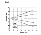
- the different dispersion values are 10 ns/nm, -10 ns/nm, 20 ns/nm and -20 ns/nm.
- the estimated normalized time delays are furthermore accompanied by a corresponding linear function for which an overall error between the function and the corresponding time delays has been minimized.
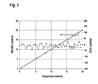
- Figure 4 shows estimated chromatic dispersion values within the range from 0 to 20 ns/nm on the ordinate together with the actual chromatic dispersion values along the abscissa. Furthermore, for each estimated dispersion value, the estimation error is given within the range of ps/nm. The results demonstrate, that using the proposed method, a very reliable estimate for the actual chromatic dispersion of an optical channel can be obtained.
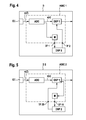
- Fig. 5 shows a device D for determining a dispersion of an optical channel according to a first embodiment.
- the device D contains an optical interface Ol which is adapted to receive an optical signal.
- the optical interface Ol is connected to an analogue digital converter ADC, which is adapted to generate a set of sampling data by sampling the optical signal.
- the device D contains a memory device M that is adapted to store sampling data.
- the analogue digital converter ADC directly writes sets of sampling data into the memory device M.
- a digital signal processor DSP2 reads out at least one set of sampling data and determines from the set of sampling data a phase at a first frequency as previously described above.
- the digital signal processor DSP2 determines a dispersion C based on the estimated phase at the first frequency.
- the digital signal processor DSP2 then passes on the estimated value for the dispersion C to another digital signal processor DSP1, which then filters the sampled optical signals by a transfer function which is inverse to the transfer function of the dispersive optical channel.
- the analogue digital converter ADC, the memory M and the digital signal processor DSP1 are integrated within an Application Specific Integrated Circuit ASIC1, providing interfaces IF1, IF2 for the signal processor DSP2 for reading the sampling data from the memory M and for passing on the estimated dispersion value C to the signal processor DSP1.
- Fig. 6 shows an alternative embodiment of a device D2 for determining dispersion of an optical channel.
- the signal processor DSP2 reads out at least one set of the filtered sampling data from the memory M and estimates a dispersion C DSP 2 , which is an estimate of the residual dispersion remaining in the sampling data after filtering it within the signal processor DSP1.
- the signal processor DSP2 then passes the estimated residual dispersion C DSP 2 on to the signal processor DSP1.
- the analogue digital converter ADC, the memory M and the digital signal processor DSP1 are integrated within an Application Specific Integrated Circuit ASIC2, providing interfaces IF11, IF22 for the signal processor DSP2 for reading the sampling data from the memory M and for passing on the estimated dispersion value C DSP 2 to the signal processor DSP1.
Landscapes
- Physics & Mathematics (AREA)
- Chemical & Material Sciences (AREA)
- Dispersion Chemistry (AREA)
- Optics & Photonics (AREA)
- Analytical Chemistry (AREA)
- General Physics & Mathematics (AREA)
- Electromagnetism (AREA)
- Engineering & Computer Science (AREA)
- Computer Networks & Wireless Communication (AREA)
- Signal Processing (AREA)
- Optical Communication System (AREA)
Abstract
The method comprises different steps. An optical signal that is transmitted via an optical transmission channel is received. The optical signal is sampled , such that a first set of sampling data is obtained. For the first set of sampling data, a frequency analysis via a spectral transform is carried out, such that a frequency component at a first frequency and frequency component at a second frequency is determined. The second frequency is chosen such that it differs from the first frequency by the symbol rate of the optical signal. Furthermore, a phase shift of a spectral density is determined, wherein the spectral density is based on the determined frequency components at the first frequency. Finally, a chromatic dispersion value of the optical transmission channel is determined based on the determined phase shift.
Description
- The invention relates to a method of determining a dispersion of an optical channel.
- When transmitting an optical signal via an optical channel with chromatic dispersion, different signal components of the optical signal having different frequencies are subject to different propagation times caused by the optical channel.
- The propagation time caused by the dispersive optical channel is a function of the chromatic dispersion. Thus, for determining the transfer function of the optical channel, the chromatic dispersion has to be determined. The optical signal can then be filtered by the inverse transfer function of the optical channel for compensating the different propagation times of different frequencies caused by the optical channel.
- A method of determining a chromatic dispersion of an optical channel is proposed.
- The method comprises different steps.
- An optical signal that is transmitted via an optical transmission channel is received. The optical signal is sampled , such that a first set of sampling data is obtained.
- For the first set of sampling data, a frequency analysis via a spectral transform is carried out, such that a frequency component at a first frequency and frequency component at a second frequency is determined. The second frequency is chosen such that it differs from the first frequency by the symbol rate of the optical signal.
- Furthermore, a phase shift of a spectral density is determined, wherein the spectral density is based on the determined frequency components at the first frequency.
- Finally, a chromatic dispersion value of the optical transmission channel is determined based on the determined phase shift.
- By choosing the second frequency, such that it differs from the first frequency by the symbol rate, it is possible to obtain from the frequency components of the sampled optical signal complex spectral density values, which contain a phase that is caused only by the phase of the transfer function of the optical transmission channel. Thus, if a relationship between the phase of the transfer function of the optical channel and the chromatic dispersion of the optical channel is known, an estimate for the chromatic dispersion can be obtained.
-
-
Figure 1 shows a discrete spectrum of a sampled signal. -
Figure 2 shows normalized time delays versus spectral indices corresponding to discrete frequency values. -
Figure 3 shows determined chromatic dispersion values in comparison to actual chromatic dispersion values, as well as the error between the determined and the actual dispersion values. -
Figure 4 shows a device for determining a chromatic dispersion of an optical channel according to an embodiment. -
Figure 5 shows a device for determining a chromatic dispersion of an optical channel according to a further embodiment. - When transmitting a real-valued time signal, s(t) via a an optical channel having a transmission function hD(t) in the time domain, the resulting signal x(t) is given by

which in the frequency domain corresponds to
- For a dispersive transmission channel, the transfer function in the frequency domain is typically given by

wherein C is the chromatic dispersion of the transmission channel and wherein fSR is the symbol rate of the optical signal. - A modulated signal s(t) can be expressed in the frequency domain as

wherein G(f) is the spectrum of a pulse function. Furthermore, ak is the modulation value, which for example for a Phase Shift Modulation such as Binary Phase Shift Keying takes on the real values ak = {-1,+1} . The symbol rate of the signal is f SR =1/T. The frequency index is k∈N. - From the received signal, one can determine the
term 
wherein ƒ 1 and ƒ 2 are chosen frequencies, and wherein X* (ƒ) is the conjugate complex of X (ƒ). - Examining the term S(ƒ1)·S* (ƒ 2), one can derive that this term becomes a real valued term with a phase of 0 for the choice of ƒ 2 = f 1 - fSR · Looking at

and taking into account that G(ƒ1) · G* (ƒ2) is a real valued spectral density, the phase of S(ƒ1)·S*(ƒ2) is for the choice of ƒ2 = ƒ1 - ƒSR equal to
- The phase finally degenerates for the choice of ƒ 2 = ƒ 1 - ƒSR to

- Thus, when determining the phase of the
term 
all that remains is
- Using the transfer function

it directly follows that one arrives at
- Thus, by taking the phase of the term X(ƒ1)-X*(ƒ2) derived from the received signal x(t) for the choice of ƒ 2 = ƒ1 - ƒSR , it is possible to estimate the chromatic dispersion value C of the optical transmission channel.
- Furthermore, since the transfer function of an optical channel with chromatic dispersion can be interpreted as a frequency response

introducing a time delay τ(C,ƒ) that depends on the frequency f and the dispersion C, it is possible to derive from an estimated dispersion value C an estimate of the time delay τ(C, ƒ). - Therefore, it is an aim of the proposed method to determine an estimate of the chromatic dispersion C based on the received signal x(t).
- After transmission of the signal s(t) via the optical transmission channel the signal x(t) is received, which then is sampled at a sampling rate ƒSA leading to a set of sampling data as

wherein n is the discrete time-index of the sets of sampling data and wherein N is the size of the set of sampling data. The symbol rate ƒSR of the optical signal is defined by the number of samples x(n) representing a transmitted symbol. For a sampling frequency of 80 GHz, a typical value is to have two samples forming a symbol such that the symbol rate fSR is half of the sampling rate ƒSA . - Using the discrete Fourier transform (DFT), a frequency analysis is carried out for the set of sampling data of x(n), yielding the complex discrete frequency values

wherein the frequency index is typically chosen as k = 0... N . -
Figure 1 depicts the discrete spectrum of a sampled signal. The discrete frequency index k = N corresponds to the sampling frequency ƒSA , while for the case of 2 samples representing a symbol, the symbol rate ƒSR corresponds to the discrete frequency index k = Nl2. It is to be noted that for a discrete spectrum obtained via a DFT, the discrete frequency range Nl2 <k<N represents the negative part of the continuous frequency range - ƒs /2<ƒ< 0 obtained via a Fourier Transform. Therefore, when choosing the first frequency to N/4 ≡ ƒSR /2= ƒ 1 and obeying ƒ 2 = f1 - ƒSR, thediscrete frequency 3N/4 represents the continuous frequency f 2. - A power-spectral density value Z c1 is determined as

- As it has been explained above, the phase of Z c1 depends only on a phase introduced by the transfer function of the optical channel. Therefore, the expression

provides an estimated phase φ, from which an estimate of a chromatic dispersion value C can be derived. The estimated value C is then used for deriving a filter function
that is inverse to the transfer function HD (ƒ) of the optical channel. The received signal x(t) is then filtered by the filter function for compensating the propagation times caused by the optical channel. This filtering may be performed in the time or in the frequency domain. - According to a preferred embodiment, the signal s(t) is transmitted in a first polarization plane via the optical channel, resulting in the signal x(t). Furthermore, the signal s(t) is transmitted also in a second polarization plane of the optical channel. At the receiving end of the transmission channel, the signal y(t) = s(t) * h(t) is received in the second polarization plane. The received signal y(t) is then sampled at the sampling rate ƒSA leading to a second set of sampling data as

- For the second set of sampling data, a frequency analysis is carried out via the Discrete Fourier Transform yielding

- For obtaining a more reliable estimate for the phase, a power spectral density Z c2 is computed as

- Furthermore, a cross-spectral density Z x1 is determined as

and another cross spectral density Z x2 as
- Averaging the two power spectral densities Z c1 and Z c2 as

and also averaging the two cross spectral densities Z x1 and Z x2 as
one can then determine the phase as
- Averaging the spectral densities via

instead of averaging them directly via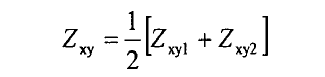
increases the signal to nose ratio of the obtained averaged spectral densities, leading to a more reliable final estimate of the phase φ and the chromatic dispersion C. This is due to the fact, that by first taking the argument of each spectral density, the magnitudes of the complex spectral densities are normalized equal to 1, while their phases remain. - The phase ø determined as described above is an estimate based on the frequencies ƒ 1 and f 2. In the following, it will be explained, in which way another estimate for a phase based on other frequencies can be obtained and in which way this other estimated phase contributes to an even more reliable estimate of the chromatic dispersion C.
- The further discrete frequency

is chosen together with another further discrete frequency
- Also for these discrete frequencies

and
with m ≡ Δƒ, the distance between their corresponding continuous frequencies is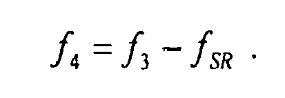
- Therefore, also the phase of the term

vanishes. - Therefore, the power spectral densities


and the cross spectral densities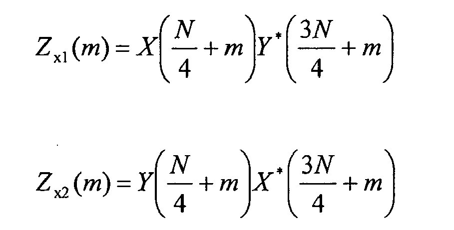
each have a phase that depends only the phase introduced by the transmission channel. - The spectral densities are then averaged via


for reliably estimating a further phase φ(m) as
- When choosing as the number of samples N of a sampling set to N =1024, a typical value of m is within the range

- When choosing the discrete frequency N/4 as initially proposed, this is equal to the choice of m = 0 , leading to an estimate of the phase as φ(0). Furthermore, by choosing m =1, one obtains another estimated phase φ(1).
- Since it is known, as previously described above, that the phase φ is a function which is dependent on the dispersion C, the two values φ(0), φ(1) can be used for determining the dispersion C, by fitting a function that represents the dependency of the phase from the chromatic dispersion C to these two estimated values via a regression. In the case that the phase is a linear function of the dispersion C, a linear function may be fitted to the estimated phase values via linear regression. Alternatively, the dispersion value C may be determined by fitting a function of higher order to the estimated phase values.
- By varying m = 0 within the range m = -M ... M, one can obtain multiple estimates φ(m), which then contribute via a fitting of a function to these estimates to an even more reliable estimate of the chromatic dispersion C.
- One can then derive an estimate for the physical link dispersion D from the equation

wherein c is the velocity of light, λ is the optical wavelength, B is the symbol rate and N is the number of samples. - The fitting of the function to the estimated values of the phase may be formed by minimizing an overall error between the function and the estimated phases φ(m).
- According to a preferred embodiment, the power-spectral densities Z c1 (m), Z c2 (m) and the cross-spectral densities Z x1 (m) , Z x2 (m) are normalized prior to averaging them via


- For the normalization, the choice of m = 0 for choosing the expression Z (m = 0) to which a spectral density Z (m) is normalized is only exemplarily, m may also be chosen to an other value.
- By this normalization, the estimated phase at a certain frequency N/4 + m is reduced to the difference of this phase at this frequency and the phase at the frequency N/4. This has the advantage, that the subsequent step of averaging yields more reliable estimates with a minimized variance.
- Furthermore, in order to provide an estimate of the phase with little variation of the signal-to-noise ratio versus the polarization state of the signal, one can weight the averaged power-spectral density Z c (m) and the averaged cross-spectral density Z x (m) by individual weighting-factors w c and w x, which can be determined as


leading to
- Furthermore, in order to take into account also phase components lying out of the range of

one can determine the phase φ(m) as
for increasing the reliability of the estimated phase. - In order to reduce the variance of the estimated phases, the estimation is based on further sets of sampling data. These further sets of sampling data are obtained by sampling the signals x(t), y(t) at further time instances.
- In the discrete time domain, a further set of sampling data obtained from the signal x(t) can be expressed as x(n+l·N), where l is the index of set of sampling data varying within the range l=0...L-1, while L typically has the value 256.
- A time-discrete representation of a further set of sampling data is then given as y(n+l·N).
- For each set of sampling data x(n+l·N) the discrete frequency values are then given by

while for each set of sampling data y(n+l·N) the discrete frequency values are given by
- Power-spectral densities for the different sets of sampling data can then be obtained as

and
while cross-spectral densities can be obtained for each set as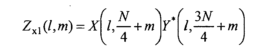
and
- Preferably, these spectral densities are then normalized as previously described above.
- Averaged power and cross spectral densities are then obtained by averaging over the different sets via

and
- Weighting of the averaged power- and cross- spectral densities can then be carried out for obtaining an estimated phase

wherein the weighting coefficients are given as

- Furthermore, in order to take into account also phase components lying out of the range of

one can determine the phase φ(m) as previously described above via
for increasing the reliability of the estimated phase. - For reducing the computational complexity of the proposed method, corresponding sets of sampling data x(M+l·N), y(n + l · N) are selected by selecting certain values of l from the range l = 0... L, leading to a set of selected indices l ∈ Λ. Then, the different steps of the proposed method are carried out relying only on those sets of sampling data x(n + l · N), y(n + l · N) for which l ∈ Λ.
-
Figure 3 shows normalized time delays τ(m) obtained from estimated phases φ(m) for different spectral lines within the range m=0 to 32 for different dispersion values at an overall signal-to-noise ratio of 15db . Exploiting the averaging over different sets of sampling data, wherein l = 256 , with a set of sampling data having n =1024, the shown results have been obtained. The different dispersion values are 10 ns/nm, -10 ns/nm, 20 ns/nm and -20 ns/nm. For each of these dispersion values the estimated normalized time delays are furthermore accompanied by a corresponding linear function for which an overall error between the function and the corresponding time delays has been minimized. -
Figure 4 shows estimated chromatic dispersion values within the range from 0 to 20 ns/nm on the ordinate together with the actual chromatic dispersion values along the abscissa. Furthermore, for each estimated dispersion value, the estimation error is given within the range of ps/nm. The results demonstrate, that using the proposed method, a very reliable estimate for the actual chromatic dispersion of an optical channel can be obtained. -
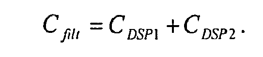
Fig. 5 shows a device D for determining a dispersion of an optical channel according to a first embodiment. The device D contains an optical interface Ol which is adapted to receive an optical signal. The optical interface Ol is connected to an analogue digital converter ADC, which is adapted to generate a set of sampling data by sampling the optical signal. Furthermore, the device D contains a memory device M that is adapted to store sampling data. According to this embodiment, the analogue digital converter ADC directly writes sets of sampling data into the memory device M. From the memory device M, a digital signal processor DSP2 reads out at least one set of sampling data and determines from the set of sampling data a phase at a first frequency as previously described above. Furthermore, the digital signal processor DSP2 determines a dispersion C based on the estimated phase at the first frequency. The digital signal processor DSP2 then passes on the estimated value for the dispersion C to another digital signal processor DSP1, which then filters the sampled optical signals by a transfer function which is inverse to the transfer function of the dispersive optical channel. Preferably, the analogue digital converter ADC, the memory M and the digital signal processor DSP1 are integrated within an Application Specific Integrated Circuit ASIC1, providing interfaces IF1, IF2 for the signal processor DSP2 for reading the sampling data from the memory M and for passing on the estimated dispersion value C to the signal processor DSP1. - Fig. 6 shows an alternative embodiment of a device D2 for determining dispersion of an optical channel. The difference between the device D and the device D2 is, that the sampling data is first filtered by the signal processor DSP1 by a filter function assuming a dispersion value Cfilt = C DSP1. Then, the filtered sampling data is written into the memory M by the signal processor DSP1 after filtering. The signal processor DSP2 reads out at least one set of the filtered sampling data from the memory M and estimates a dispersion C DSP2, which is an estimate of the residual dispersion remaining in the sampling data after filtering it within the signal processor DSP1. The signal processor DSP2 then passes the estimated residual dispersion C DSP2 on to the signal processor DSP1. The signal processor DSP1 then uses in a next cycle of filtering the sampling data a filter function based on the dispersion value
- Preferably, the analogue digital converter ADC, the memory M and the digital signal processor DSP1 are integrated within an Application Specific Integrated Circuit ASIC2, providing interfaces IF11, IF22 for the signal processor DSP2 for reading the sampling data from the memory M and for passing on the estimated dispersion value C DSP2 to the signal processor DSP1.
Claims (10)
- Method of determining a dispersion of an optical channel,
comprising the steps ofa) receiving an optical signal transmitted via an optical transmission channel,b) generating a first set of sampling data x(n) by sampling said optical signal,d) determining via a spectral transform for said first set of sampling data x(n)- a frequency component at a first frequency ƒ 1, and- a frequency component at a second frequency f 2,
wherein said second frequency ƒ 2 is chosen such that it differs from said first frequency ƒ 1 by a symbol rate ƒSR of said optical signal,e) determining a phase value based on said frequency components of said first set of sampling data x(n),f) determining a dispersion value C based on said phase value. - Method according to claim 1,
wherein in step b) said optical signal is sampled in a first polarization plane,
comprising the further steps ofg) generating a second set of sampling data y(n) by sampling said optical signal in a second polarization plane,h) determining via said spectral transform for said second set of sampling data y(n)- a frequency component at said first frequency ƒ 1, and- a frequency component at said second frequency ƒ 2,i) determining said phase value based on said frequency components of said first and said second set of sampling data x(n), y(n). - Method according to claim 2,
comprising the further steps ofj) determining via said spectral transform for said first set of sampling data x(n)- a frequency component at a third frequency ƒ 3, and- a frequency component at a fourth frequency ƒ 4,
wherein said fourth frequency ƒ 4 is chosen such that it differs from said third frequency ƒ 3 by said symbol rate ƒSR ,k) determining via said spectral transform for said second set of sampling data y(n)- a frequency component at said third frequency ƒ 3, and- a frequency component at said fourth frequency ƒ 4,l) determining a further phase value based on- said frequency components at said third frequency ƒ 3 of said first and said second set of sampling data x(n), y(n), and- said frequency components at said fourth frequency ƒ 4 of said first and said second set of sampling data x(n), y(n),m) determining said dispersion value C based on said first phase value and said further phase value. - Method according to claim 3,
wherein said dispersion value C is determined by a fitting a function representing the dependency of the phase from the dispersion value C to said determined phase values. - Method according to any of the claims 2 to 4,
wherein said step i) comprises the sub-steps of
i1) determining- a first power spectral density from said frequency components of said first set, and- a second power spectral density from said frequency components of said second set,i2) determining- a first cross spectral density, and- a second cross spectral density,i3) obtaining an average power spectral density from said first and said second power spectral density,
from said frequency components of said first and said second set of sampling data,
i4) obtaining an average cross spectral density from said first and said second cross spectral density,
i5) determining said phase value based on said averaged power spectral density and said averaged cross spectral density. - Method according to claim 5,
wherein said sub-step i3) includes normalizing said first and said second power spectral density,
and wherein said sub-step i4) includes normalizing said first and said second cross spectral density. - Method according to claim 5 or 6,
wherein said sub-step i5) includes weighting of said averaged power spectral density and said averaged cross spectral density by respective weighting coefficients, wherein said weighting coefficients are functions of said frequency components of said first and said second set. - Method according to any of the claims 1 to 7,
comprising the further steps ofm) generating first further sets of sampling data by sampling said optical signal in said first polarization plane,n) generating second further sets of sampling data by sampling said optical signal in said second polarization plane,p) determining via said spectral transform for each of said first further sets corresponding frequency components at said frequencies, and determining via said spectral transform for each of said second further sets corresponding frequency components at said frequencies,wherein in step i) said phase value is determined based on said frequency components at said first and said second frequency of said further sets,
and wherein in step l) said further phase value is determined based on said frequency components at said third and said fourth frequency of said further sets. - Method according to any of the claims 1 to 8,
wherein prior to said step d) said first sampling data and said second sampling data is filtered by a filter function for compensating a chromatic dispersion of said optical transmission channel, and wherein said dispersion value determined in any of the preceding claims is a residual dispersion value. - Device for determining a dispersion of an optical channel
comprising- an optical interface (OI) adapted to receive an optical signal,- a memory device (M) adapted to store sampling data,- an analogue-digital-converter (ADC) adapted o to generate a set of sampling data by sampling said optical signal, and- at least one digital signal processing device (DSP1, DSP2) adaptedo to read said at least one set of sampling data from said memory device (M), ando to carry out the steps d), e) and f) of claim 1.
Priority Applications (1)
| Application Number | Priority Date | Filing Date | Title |
|---|---|---|---|
| EP10290170.9A EP2372332B1 (en) | 2010-03-31 | 2010-03-31 | Method for determining a chromatic dispersion of an optical channel |
Applications Claiming Priority (1)
| Application Number | Priority Date | Filing Date | Title |
|---|---|---|---|
| EP10290170.9A EP2372332B1 (en) | 2010-03-31 | 2010-03-31 | Method for determining a chromatic dispersion of an optical channel |
Publications (2)
| Publication Number | Publication Date |
|---|---|
| EP2372332A1 true EP2372332A1 (en) | 2011-10-05 |
| EP2372332B1 EP2372332B1 (en) | 2017-09-06 |
Family
ID=42584400
Family Applications (1)
| Application Number | Title | Priority Date | Filing Date |
|---|---|---|---|
| EP10290170.9A Not-in-force EP2372332B1 (en) | 2010-03-31 | 2010-03-31 | Method for determining a chromatic dispersion of an optical channel |
Country Status (1)
| Country | Link |
|---|---|
| EP (1) | EP2372332B1 (en) |
Cited By (2)
| Publication number | Priority date | Publication date | Assignee | Title |
|---|---|---|---|---|
| EP2849362A1 (en) | 2013-09-11 | 2015-03-18 | Alcatel Lucent | Blind frequency offset estimation for pulse-shaped signals |
| GB2538141A (en) * | 2015-03-09 | 2016-11-09 | Eci Telecom Ltd | Channel performance monitoring and an optical communication system using same |
Families Citing this family (1)
| Publication number | Priority date | Publication date | Assignee | Title |
|---|---|---|---|---|
| US11290184B2 (en) | 2019-03-01 | 2022-03-29 | Molex, Llc | Switchable dispersion compensating module |
Citations (10)
| Publication number | Priority date | Publication date | Assignee | Title |
|---|---|---|---|---|
| US5406368A (en) * | 1993-07-06 | 1995-04-11 | Kokusai Denshin Denwa Kabushiki Kaisha | Method and apparatus for chromatic dispersion measurements |
| US6088088A (en) * | 1999-03-31 | 2000-07-11 | Hewlett-Packard Company | Chromatic dispersion measurement scheme having high frequency resolution |
| EP1160559A2 (en) * | 2000-06-02 | 2001-12-05 | Agilent Technologies, Inc. (a Delaware corporation) | Time delay measurement using optical signals modulated at multiple frequencies |
| US20030123884A1 (en) * | 2001-07-09 | 2003-07-03 | Willner Alan E. | Monitoring optical dispersion based on vestigial side band optical filtering |
| WO2003092194A1 (en) * | 2002-04-24 | 2003-11-06 | Eci Telecom Ltd. | Chromatic dispersion measurement and compensation |
| US20050110981A1 (en) * | 2003-11-26 | 2005-05-26 | Michiaki Hayashi | Method and apparatus for measuring chromatic dispersion |
| EP1645861A1 (en) * | 2004-10-06 | 2006-04-12 | Acterna Germany GmbH | Device for and method of measuring the chromatic dispersion of an optical transmission section |
| EP1655592A1 (en) * | 2003-08-12 | 2006-05-10 | Bussan Nanotech Research Institute Inc. | Detection device, optical path length measurement device, measurement instrument, optical member evaluation method, and temperature change detection method |
| US20060109452A1 (en) * | 2004-11-23 | 2006-05-25 | Eberhard Loecklin | Device and method for chromatic dispersion measurement |
| US20090297140A1 (en) * | 2008-05-29 | 2009-12-03 | Actena Llc | Measuring chromatic dispersion in an optical wavelength channel of an optical fiber link |
-
2010
- 2010-03-31 EP EP10290170.9A patent/EP2372332B1/en not_active Not-in-force
Patent Citations (10)
| Publication number | Priority date | Publication date | Assignee | Title |
|---|---|---|---|---|
| US5406368A (en) * | 1993-07-06 | 1995-04-11 | Kokusai Denshin Denwa Kabushiki Kaisha | Method and apparatus for chromatic dispersion measurements |
| US6088088A (en) * | 1999-03-31 | 2000-07-11 | Hewlett-Packard Company | Chromatic dispersion measurement scheme having high frequency resolution |
| EP1160559A2 (en) * | 2000-06-02 | 2001-12-05 | Agilent Technologies, Inc. (a Delaware corporation) | Time delay measurement using optical signals modulated at multiple frequencies |
| US20030123884A1 (en) * | 2001-07-09 | 2003-07-03 | Willner Alan E. | Monitoring optical dispersion based on vestigial side band optical filtering |
| WO2003092194A1 (en) * | 2002-04-24 | 2003-11-06 | Eci Telecom Ltd. | Chromatic dispersion measurement and compensation |
| EP1655592A1 (en) * | 2003-08-12 | 2006-05-10 | Bussan Nanotech Research Institute Inc. | Detection device, optical path length measurement device, measurement instrument, optical member evaluation method, and temperature change detection method |
| US20050110981A1 (en) * | 2003-11-26 | 2005-05-26 | Michiaki Hayashi | Method and apparatus for measuring chromatic dispersion |
| EP1645861A1 (en) * | 2004-10-06 | 2006-04-12 | Acterna Germany GmbH | Device for and method of measuring the chromatic dispersion of an optical transmission section |
| US20060109452A1 (en) * | 2004-11-23 | 2006-05-25 | Eberhard Loecklin | Device and method for chromatic dispersion measurement |
| US20090297140A1 (en) * | 2008-05-29 | 2009-12-03 | Actena Llc | Measuring chromatic dispersion in an optical wavelength channel of an optical fiber link |
Cited By (3)
| Publication number | Priority date | Publication date | Assignee | Title |
|---|---|---|---|---|
| EP2849362A1 (en) | 2013-09-11 | 2015-03-18 | Alcatel Lucent | Blind frequency offset estimation for pulse-shaped signals |
| GB2538141A (en) * | 2015-03-09 | 2016-11-09 | Eci Telecom Ltd | Channel performance monitoring and an optical communication system using same |
| GB2538141B (en) * | 2015-03-09 | 2021-06-02 | Eci Telecom Ltd | A method for carrying out channel performance monitoring and an optical communication system using same |
Also Published As
| Publication number | Publication date |
|---|---|
| EP2372332B1 (en) | 2017-09-06 |
Similar Documents
| Publication | Publication Date | Title |
|---|---|---|
| EP0140925B1 (en) | Modulation detector and classifier | |
| US7054358B2 (en) | Measuring apparatus and measuring method | |
| RU2513044C2 (en) | Filter device | |
| US20120096061A1 (en) | Adaptive filter | |
| US20250047534A1 (en) | Delay-doppler domain channel estimation and frame synchronization | |
| EP3506174A1 (en) | System for demodulation or blind search of the characteristics of digital telecommunications signals | |
| EP2372332B1 (en) | Method for determining a chromatic dispersion of an optical channel | |
| US20040125893A1 (en) | Methods and systems for tracking of amplitudes, phases and frequencies of a multi-component sinusoidal signal | |
| EP2361389B1 (en) | Device and method of distributed reflectometry for diagnosing a transmission network | |
| US12212360B2 (en) | Spatially resolved monitoring of cable perturbations using multichannel information | |
| US20050063323A1 (en) | Method and circuit arrangement for determination of transmission parameters | |
| EP1113634B1 (en) | Method for transmission channel estimation | |
| CN102027680B (en) | For detection of and for generating method and relevant device and the communication system of useful signal | |
| TWI363567B (en) | Apparatus and method arranged to analyse a signal comprising a series of symbols | |
| CN110120925B (en) | Time delay estimation method based on short wave diversity signals | |
| CN114726450B (en) | A dispersion-tolerant clock recovery method and system | |
| CN102307164B (en) | digital frequency estimation method and system | |
| US20240259095A1 (en) | Waveguide estimation apparatus, waveguide estimation method and program | |
| CN101622611B (en) | Use the high speed digital waveform identification of higher order statistical signal process | |
| CN118249939A (en) | A method, device and electronic equipment for establishing a satellite channel model | |
| US20260056285A1 (en) | Radar device and estimation method | |
| CN110460551A (en) | A kind of channel carrier phase recovery method based on least mean-square error | |
| US20260056289A1 (en) | Radar device and estimation method | |
| US7852912B2 (en) | Direct determination equalizer system | |
| US20250219726A1 (en) | Method for Testing TDEC and Related Device |
Legal Events
| Date | Code | Title | Description |
|---|---|---|---|
| PUAI | Public reference made under article 153(3) epc to a published international application that has entered the european phase |
Free format text: ORIGINAL CODE: 0009012 |
|
| 17P | Request for examination filed |
Effective date: 20110204 |
|
| AK | Designated contracting states |
Kind code of ref document: A1 Designated state(s): AT BE BG CH CY CZ DE DK EE ES FI FR GB GR HR HU IE IS IT LI LT LU LV MC MK MT NL NO PL PT RO SE SI SK SM TR |
|
| AX | Request for extension of the european patent |
Extension state: AL BA ME RS |
|
| RAP1 | Party data changed (applicant data changed or rights of an application transferred) |
Owner name: ALCATEL LUCENT |
|
| 111Z | Information provided on other rights and legal means of execution |
Free format text: AT BE BG CH CY CZ DE DK EE ES FI FR GB GR HR HU IE IS IT LI LT LU LV MC MK MT NL NO PL PT RO SE SI SK SM TR Effective date: 20130410 |
|
| RAP1 | Party data changed (applicant data changed or rights of an application transferred) |
Owner name: ALCATEL LUCENT |
|
| D11X | Information provided on other rights and legal means of execution (deleted) | ||
| 17Q | First examination report despatched |
Effective date: 20160907 |
|
| GRAP | Despatch of communication of intention to grant a patent |
Free format text: ORIGINAL CODE: EPIDOSNIGR1 |
|
| RIC1 | Information provided on ipc code assigned before grant |
Ipc: G01M 11/00 20060101AFI20170214BHEP Ipc: H04B 10/079 20130101ALI20170214BHEP |
|
| INTG | Intention to grant announced |
Effective date: 20170322 |
|
| GRAS | Grant fee paid |
Free format text: ORIGINAL CODE: EPIDOSNIGR3 |
|
| GRAA | (expected) grant |
Free format text: ORIGINAL CODE: 0009210 |
|
| AK | Designated contracting states |
Kind code of ref document: B1 Designated state(s): AT BE BG CH CY CZ DE DK EE ES FI FR GB GR HR HU IE IS IT LI LT LU LV MC MK MT NL NO PL PT RO SE SI SK SM TR |
|
| REG | Reference to a national code |
Ref country code: GB Ref legal event code: FG4D |
|
| REG | Reference to a national code |
Ref country code: CH Ref legal event code: EP Ref country code: AT Ref legal event code: REF Ref document number: 926387 Country of ref document: AT Kind code of ref document: T Effective date: 20170915 |
|
| REG | Reference to a national code |
Ref country code: IE Ref legal event code: FG4D |
|
| REG | Reference to a national code |
Ref country code: DE Ref legal event code: R096 Ref document number: 602010044986 Country of ref document: DE |
|
| REG | Reference to a national code |
Ref country code: NL Ref legal event code: MP Effective date: 20170906 |
|
| REG | Reference to a national code |
Ref country code: LT Ref legal event code: MG4D |
|
| PG25 | Lapsed in a contracting state [announced via postgrant information from national office to epo] |
Ref country code: NO Free format text: LAPSE BECAUSE OF FAILURE TO SUBMIT A TRANSLATION OF THE DESCRIPTION OR TO PAY THE FEE WITHIN THE PRESCRIBED TIME-LIMIT Effective date: 20171206 Ref country code: SE Free format text: LAPSE BECAUSE OF FAILURE TO SUBMIT A TRANSLATION OF THE DESCRIPTION OR TO PAY THE FEE WITHIN THE PRESCRIBED TIME-LIMIT Effective date: 20170906 Ref country code: LT Free format text: LAPSE BECAUSE OF FAILURE TO SUBMIT A TRANSLATION OF THE DESCRIPTION OR TO PAY THE FEE WITHIN THE PRESCRIBED TIME-LIMIT Effective date: 20170906 Ref country code: HR Free format text: LAPSE BECAUSE OF FAILURE TO SUBMIT A TRANSLATION OF THE DESCRIPTION OR TO PAY THE FEE WITHIN THE PRESCRIBED TIME-LIMIT Effective date: 20170906 Ref country code: FI Free format text: LAPSE BECAUSE OF FAILURE TO SUBMIT A TRANSLATION OF THE DESCRIPTION OR TO PAY THE FEE WITHIN THE PRESCRIBED TIME-LIMIT Effective date: 20170906 |
|
| REG | Reference to a national code |
Ref country code: AT Ref legal event code: MK05 Ref document number: 926387 Country of ref document: AT Kind code of ref document: T Effective date: 20170906 |
|
| PG25 | Lapsed in a contracting state [announced via postgrant information from national office to epo] |
Ref country code: GR Free format text: LAPSE BECAUSE OF FAILURE TO SUBMIT A TRANSLATION OF THE DESCRIPTION OR TO PAY THE FEE WITHIN THE PRESCRIBED TIME-LIMIT Effective date: 20171207 Ref country code: ES Free format text: LAPSE BECAUSE OF FAILURE TO SUBMIT A TRANSLATION OF THE DESCRIPTION OR TO PAY THE FEE WITHIN THE PRESCRIBED TIME-LIMIT Effective date: 20170906 Ref country code: LV Free format text: LAPSE BECAUSE OF FAILURE TO SUBMIT A TRANSLATION OF THE DESCRIPTION OR TO PAY THE FEE WITHIN THE PRESCRIBED TIME-LIMIT Effective date: 20170906 Ref country code: BG Free format text: LAPSE BECAUSE OF FAILURE TO SUBMIT A TRANSLATION OF THE DESCRIPTION OR TO PAY THE FEE WITHIN THE PRESCRIBED TIME-LIMIT Effective date: 20171206 |
|
| REG | Reference to a national code |
Ref country code: CH Ref legal event code: PCOW Free format text: NEW ADDRESS: SITE NOKIA PARIS SACLAY ROUTE DE VILLEJUST, 91620 NOZAY (FR) |
|
| PG25 | Lapsed in a contracting state [announced via postgrant information from national office to epo] |
Ref country code: NL Free format text: LAPSE BECAUSE OF FAILURE TO SUBMIT A TRANSLATION OF THE DESCRIPTION OR TO PAY THE FEE WITHIN THE PRESCRIBED TIME-LIMIT Effective date: 20170906 |
|
| RAP2 | Party data changed (patent owner data changed or rights of a patent transferred) |
Owner name: ALCATEL LUCENT |
|
| PG25 | Lapsed in a contracting state [announced via postgrant information from national office to epo] |
Ref country code: RO Free format text: LAPSE BECAUSE OF FAILURE TO SUBMIT A TRANSLATION OF THE DESCRIPTION OR TO PAY THE FEE WITHIN THE PRESCRIBED TIME-LIMIT Effective date: 20170906 Ref country code: PL Free format text: LAPSE BECAUSE OF FAILURE TO SUBMIT A TRANSLATION OF THE DESCRIPTION OR TO PAY THE FEE WITHIN THE PRESCRIBED TIME-LIMIT Effective date: 20170906 Ref country code: CZ Free format text: LAPSE BECAUSE OF FAILURE TO SUBMIT A TRANSLATION OF THE DESCRIPTION OR TO PAY THE FEE WITHIN THE PRESCRIBED TIME-LIMIT Effective date: 20170906 |
|
| PG25 | Lapsed in a contracting state [announced via postgrant information from national office to epo] |
Ref country code: SM Free format text: LAPSE BECAUSE OF FAILURE TO SUBMIT A TRANSLATION OF THE DESCRIPTION OR TO PAY THE FEE WITHIN THE PRESCRIBED TIME-LIMIT Effective date: 20170906 Ref country code: SK Free format text: LAPSE BECAUSE OF FAILURE TO SUBMIT A TRANSLATION OF THE DESCRIPTION OR TO PAY THE FEE WITHIN THE PRESCRIBED TIME-LIMIT Effective date: 20170906 Ref country code: AT Free format text: LAPSE BECAUSE OF FAILURE TO SUBMIT A TRANSLATION OF THE DESCRIPTION OR TO PAY THE FEE WITHIN THE PRESCRIBED TIME-LIMIT Effective date: 20170906 Ref country code: IS Free format text: LAPSE BECAUSE OF FAILURE TO SUBMIT A TRANSLATION OF THE DESCRIPTION OR TO PAY THE FEE WITHIN THE PRESCRIBED TIME-LIMIT Effective date: 20180106 Ref country code: IT Free format text: LAPSE BECAUSE OF FAILURE TO SUBMIT A TRANSLATION OF THE DESCRIPTION OR TO PAY THE FEE WITHIN THE PRESCRIBED TIME-LIMIT Effective date: 20170906 Ref country code: EE Free format text: LAPSE BECAUSE OF FAILURE TO SUBMIT A TRANSLATION OF THE DESCRIPTION OR TO PAY THE FEE WITHIN THE PRESCRIBED TIME-LIMIT Effective date: 20170906 |
|
| REG | Reference to a national code |
Ref country code: DE Ref legal event code: R097 Ref document number: 602010044986 Country of ref document: DE |
|
| PLBE | No opposition filed within time limit |
Free format text: ORIGINAL CODE: 0009261 |
|
| STAA | Information on the status of an ep patent application or granted ep patent |
Free format text: STATUS: NO OPPOSITION FILED WITHIN TIME LIMIT |
|
| PG25 | Lapsed in a contracting state [announced via postgrant information from national office to epo] |
Ref country code: DK Free format text: LAPSE BECAUSE OF FAILURE TO SUBMIT A TRANSLATION OF THE DESCRIPTION OR TO PAY THE FEE WITHIN THE PRESCRIBED TIME-LIMIT Effective date: 20170906 |
|
| 26N | No opposition filed |
Effective date: 20180607 |
|
| PG25 | Lapsed in a contracting state [announced via postgrant information from national office to epo] |
Ref country code: SI Free format text: LAPSE BECAUSE OF FAILURE TO SUBMIT A TRANSLATION OF THE DESCRIPTION OR TO PAY THE FEE WITHIN THE PRESCRIBED TIME-LIMIT Effective date: 20170906 |
|
| REG | Reference to a national code |
Ref country code: DE Ref legal event code: R119 Ref document number: 602010044986 Country of ref document: DE |
|
| REG | Reference to a national code |
Ref country code: CH Ref legal event code: PL |
|
| GBPC | Gb: european patent ceased through non-payment of renewal fee |
Effective date: 20180331 |
|
| PG25 | Lapsed in a contracting state [announced via postgrant information from national office to epo] |
Ref country code: MC Free format text: LAPSE BECAUSE OF FAILURE TO SUBMIT A TRANSLATION OF THE DESCRIPTION OR TO PAY THE FEE WITHIN THE PRESCRIBED TIME-LIMIT Effective date: 20170906 |
|
| REG | Reference to a national code |
Ref country code: BE Ref legal event code: MM Effective date: 20180331 |
|
| REG | Reference to a national code |
Ref country code: IE Ref legal event code: MM4A |
|
| PG25 | Lapsed in a contracting state [announced via postgrant information from national office to epo] |
Ref country code: LU Free format text: LAPSE BECAUSE OF NON-PAYMENT OF DUE FEES Effective date: 20180331 |
|
| PG25 | Lapsed in a contracting state [announced via postgrant information from national office to epo] |
Ref country code: IE Free format text: LAPSE BECAUSE OF NON-PAYMENT OF DUE FEES Effective date: 20180331 Ref country code: DE Free format text: LAPSE BECAUSE OF NON-PAYMENT OF DUE FEES Effective date: 20181002 |
|
| PG25 | Lapsed in a contracting state [announced via postgrant information from national office to epo] |
Ref country code: LI Free format text: LAPSE BECAUSE OF NON-PAYMENT OF DUE FEES Effective date: 20180331 Ref country code: GB Free format text: LAPSE BECAUSE OF NON-PAYMENT OF DUE FEES Effective date: 20180331 Ref country code: CH Free format text: LAPSE BECAUSE OF NON-PAYMENT OF DUE FEES Effective date: 20180331 Ref country code: BE Free format text: LAPSE BECAUSE OF NON-PAYMENT OF DUE FEES Effective date: 20180331 |
|
| PG25 | Lapsed in a contracting state [announced via postgrant information from national office to epo] |
Ref country code: FR Free format text: LAPSE BECAUSE OF NON-PAYMENT OF DUE FEES Effective date: 20180331 |
|
| PG25 | Lapsed in a contracting state [announced via postgrant information from national office to epo] |
Ref country code: MT Free format text: LAPSE BECAUSE OF NON-PAYMENT OF DUE FEES Effective date: 20180331 |
|
| PG25 | Lapsed in a contracting state [announced via postgrant information from national office to epo] |
Ref country code: TR Free format text: LAPSE BECAUSE OF FAILURE TO SUBMIT A TRANSLATION OF THE DESCRIPTION OR TO PAY THE FEE WITHIN THE PRESCRIBED TIME-LIMIT Effective date: 20170906 |
|
| PG25 | Lapsed in a contracting state [announced via postgrant information from national office to epo] |
Ref country code: HU Free format text: LAPSE BECAUSE OF FAILURE TO SUBMIT A TRANSLATION OF THE DESCRIPTION OR TO PAY THE FEE WITHIN THE PRESCRIBED TIME-LIMIT; INVALID AB INITIO Effective date: 20100331 Ref country code: PT Free format text: LAPSE BECAUSE OF FAILURE TO SUBMIT A TRANSLATION OF THE DESCRIPTION OR TO PAY THE FEE WITHIN THE PRESCRIBED TIME-LIMIT Effective date: 20170906 |
|
| PG25 | Lapsed in a contracting state [announced via postgrant information from national office to epo] |
Ref country code: CY Free format text: LAPSE BECAUSE OF FAILURE TO SUBMIT A TRANSLATION OF THE DESCRIPTION OR TO PAY THE FEE WITHIN THE PRESCRIBED TIME-LIMIT Effective date: 20170906 Ref country code: MK Free format text: LAPSE BECAUSE OF NON-PAYMENT OF DUE FEES Effective date: 20170906 |