EP2372143B1 - Vorrichtung und Verfahren zum Aufrichten auf See eines schlanken Körpers wie eines Einzelpfeilers einer Windturbine - Google Patents
Vorrichtung und Verfahren zum Aufrichten auf See eines schlanken Körpers wie eines Einzelpfeilers einer Windturbine Download PDFInfo
- Publication number
- EP2372143B1 EP2372143B1 EP10158186.6A EP10158186A EP2372143B1 EP 2372143 B1 EP2372143 B1 EP 2372143B1 EP 10158186 A EP10158186 A EP 10158186A EP 2372143 B1 EP2372143 B1 EP 2372143B1
- Authority
- EP
- European Patent Office
- Prior art keywords
- fixation means
- slender body
- tension cable
- fixation
- monopile
- Prior art date
- Legal status (The legal status is an assumption and is not a legal conclusion. Google has not performed a legal analysis and makes no representation as to the accuracy of the status listed.)
- Active
Links
- 238000000034 method Methods 0.000 title claims description 47
- 150000001875 compounds Chemical class 0.000 claims description 7
- 230000005484 gravity Effects 0.000 claims description 7
- XLYOFNOQVPJJNP-UHFFFAOYSA-N water Substances O XLYOFNOQVPJJNP-UHFFFAOYSA-N 0.000 claims description 7
- 239000000758 substrate Substances 0.000 claims description 4
- 229910000831 Steel Inorganic materials 0.000 description 5
- 239000010959 steel Substances 0.000 description 5
- 230000007704 transition Effects 0.000 description 5
- 238000004804 winding Methods 0.000 description 5
- 239000000463 material Substances 0.000 description 2
- 238000010276 construction Methods 0.000 description 1
- 230000001419 dependent effect Effects 0.000 description 1
- 230000005404 monopole Effects 0.000 description 1
- 230000001360 synchronised effect Effects 0.000 description 1
Images


Classifications
-
- F—MECHANICAL ENGINEERING; LIGHTING; HEATING; WEAPONS; BLASTING
- F03—MACHINES OR ENGINES FOR LIQUIDS; WIND, SPRING, OR WEIGHT MOTORS; PRODUCING MECHANICAL POWER OR A REACTIVE PROPULSIVE THRUST, NOT OTHERWISE PROVIDED FOR
- F03D—WIND MOTORS
- F03D13/00—Assembly, mounting or commissioning of wind motors; Arrangements specially adapted for transporting wind motor components
- F03D13/10—Assembly of wind motors; Arrangements for erecting wind motors
-
- E—FIXED CONSTRUCTIONS
- E02—HYDRAULIC ENGINEERING; FOUNDATIONS; SOIL SHIFTING
- E02B—HYDRAULIC ENGINEERING
- E02B17/00—Artificial islands mounted on piles or like supports, e.g. platforms on raisable legs or offshore constructions; Construction methods therefor
- E02B17/02—Artificial islands mounted on piles or like supports, e.g. platforms on raisable legs or offshore constructions; Construction methods therefor placed by lowering the supporting construction to the bottom, e.g. with subsequent fixing thereto
- E02B17/027—Artificial islands mounted on piles or like supports, e.g. platforms on raisable legs or offshore constructions; Construction methods therefor placed by lowering the supporting construction to the bottom, e.g. with subsequent fixing thereto steel structures
-
- E—FIXED CONSTRUCTIONS
- E02—HYDRAULIC ENGINEERING; FOUNDATIONS; SOIL SHIFTING
- E02D—FOUNDATIONS; EXCAVATIONS; EMBANKMENTS; UNDERGROUND OR UNDERWATER STRUCTURES
- E02D27/00—Foundations as substructures
- E02D27/32—Foundations for special purposes
- E02D27/42—Foundations for poles, masts or chimneys
-
- F—MECHANICAL ENGINEERING; LIGHTING; HEATING; WEAPONS; BLASTING
- F03—MACHINES OR ENGINES FOR LIQUIDS; WIND, SPRING, OR WEIGHT MOTORS; PRODUCING MECHANICAL POWER OR A REACTIVE PROPULSIVE THRUST, NOT OTHERWISE PROVIDED FOR
- F03D—WIND MOTORS
- F03D13/00—Assembly, mounting or commissioning of wind motors; Arrangements specially adapted for transporting wind motor components
- F03D13/20—Arrangements for mounting or supporting wind motors; Masts or towers for wind motors
- F03D13/22—Foundations specially adapted for wind motors
-
- E—FIXED CONSTRUCTIONS
- E02—HYDRAULIC ENGINEERING; FOUNDATIONS; SOIL SHIFTING
- E02B—HYDRAULIC ENGINEERING
- E02B17/00—Artificial islands mounted on piles or like supports, e.g. platforms on raisable legs or offshore constructions; Construction methods therefor
- E02B2017/0039—Methods for placing the offshore structure
-
- E—FIXED CONSTRUCTIONS
- E02—HYDRAULIC ENGINEERING; FOUNDATIONS; SOIL SHIFTING
- E02B—HYDRAULIC ENGINEERING
- E02B17/00—Artificial islands mounted on piles or like supports, e.g. platforms on raisable legs or offshore constructions; Construction methods therefor
- E02B2017/0056—Platforms with supporting legs
- E02B2017/0065—Monopile structures
-
- E—FIXED CONSTRUCTIONS
- E02—HYDRAULIC ENGINEERING; FOUNDATIONS; SOIL SHIFTING
- E02B—HYDRAULIC ENGINEERING
- E02B17/00—Artificial islands mounted on piles or like supports, e.g. platforms on raisable legs or offshore constructions; Construction methods therefor
- E02B2017/0091—Offshore structures for wind turbines
-
- F—MECHANICAL ENGINEERING; LIGHTING; HEATING; WEAPONS; BLASTING
- F05—INDEXING SCHEMES RELATING TO ENGINES OR PUMPS IN VARIOUS SUBCLASSES OF CLASSES F01-F04
- F05B—INDEXING SCHEME RELATING TO WIND, SPRING, WEIGHT, INERTIA OR LIKE MOTORS, TO MACHINES OR ENGINES FOR LIQUIDS COVERED BY SUBCLASSES F03B, F03D AND F03G
- F05B2230/00—Manufacture
- F05B2230/60—Assembly methods
-
- F—MECHANICAL ENGINEERING; LIGHTING; HEATING; WEAPONS; BLASTING
- F05—INDEXING SCHEMES RELATING TO ENGINES OR PUMPS IN VARIOUS SUBCLASSES OF CLASSES F01-F04
- F05B—INDEXING SCHEME RELATING TO WIND, SPRING, WEIGHT, INERTIA OR LIKE MOTORS, TO MACHINES OR ENGINES FOR LIQUIDS COVERED BY SUBCLASSES F03B, F03D AND F03G
- F05B2240/00—Components
- F05B2240/90—Mounting on supporting structures or systems
- F05B2240/95—Mounting on supporting structures or systems offshore
-
- Y—GENERAL TAGGING OF NEW TECHNOLOGICAL DEVELOPMENTS; GENERAL TAGGING OF CROSS-SECTIONAL TECHNOLOGIES SPANNING OVER SEVERAL SECTIONS OF THE IPC; TECHNICAL SUBJECTS COVERED BY FORMER USPC CROSS-REFERENCE ART COLLECTIONS [XRACs] AND DIGESTS
- Y02—TECHNOLOGIES OR APPLICATIONS FOR MITIGATION OR ADAPTATION AGAINST CLIMATE CHANGE
- Y02E—REDUCTION OF GREENHOUSE GAS [GHG] EMISSIONS, RELATED TO ENERGY GENERATION, TRANSMISSION OR DISTRIBUTION
- Y02E10/00—Energy generation through renewable energy sources
- Y02E10/70—Wind energy
- Y02E10/72—Wind turbines with rotation axis in wind direction
-
- Y—GENERAL TAGGING OF NEW TECHNOLOGICAL DEVELOPMENTS; GENERAL TAGGING OF CROSS-SECTIONAL TECHNOLOGIES SPANNING OVER SEVERAL SECTIONS OF THE IPC; TECHNICAL SUBJECTS COVERED BY FORMER USPC CROSS-REFERENCE ART COLLECTIONS [XRACs] AND DIGESTS
- Y02—TECHNOLOGIES OR APPLICATIONS FOR MITIGATION OR ADAPTATION AGAINST CLIMATE CHANGE
- Y02E—REDUCTION OF GREENHOUSE GAS [GHG] EMISSIONS, RELATED TO ENERGY GENERATION, TRANSMISSION OR DISTRIBUTION
- Y02E10/00—Energy generation through renewable energy sources
- Y02E10/70—Wind energy
- Y02E10/727—Offshore wind turbines
-
- Y—GENERAL TAGGING OF NEW TECHNOLOGICAL DEVELOPMENTS; GENERAL TAGGING OF CROSS-SECTIONAL TECHNOLOGIES SPANNING OVER SEVERAL SECTIONS OF THE IPC; TECHNICAL SUBJECTS COVERED BY FORMER USPC CROSS-REFERENCE ART COLLECTIONS [XRACs] AND DIGESTS
- Y02—TECHNOLOGIES OR APPLICATIONS FOR MITIGATION OR ADAPTATION AGAINST CLIMATE CHANGE
- Y02P—CLIMATE CHANGE MITIGATION TECHNOLOGIES IN THE PRODUCTION OR PROCESSING OF GOODS
- Y02P70/00—Climate change mitigation technologies in the production process for final industrial or consumer products
- Y02P70/50—Manufacturing or production processes characterised by the final manufactured product
-
- Y—GENERAL TAGGING OF NEW TECHNOLOGICAL DEVELOPMENTS; GENERAL TAGGING OF CROSS-SECTIONAL TECHNOLOGIES SPANNING OVER SEVERAL SECTIONS OF THE IPC; TECHNICAL SUBJECTS COVERED BY FORMER USPC CROSS-REFERENCE ART COLLECTIONS [XRACs] AND DIGESTS
- Y10—TECHNICAL SUBJECTS COVERED BY FORMER USPC
- Y10T—TECHNICAL SUBJECTS COVERED BY FORMER US CLASSIFICATION
- Y10T29/00—Metal working
- Y10T29/49—Method of mechanical manufacture
- Y10T29/49826—Assembling or joining
-
- Y—GENERAL TAGGING OF NEW TECHNOLOGICAL DEVELOPMENTS; GENERAL TAGGING OF CROSS-SECTIONAL TECHNOLOGIES SPANNING OVER SEVERAL SECTIONS OF THE IPC; TECHNICAL SUBJECTS COVERED BY FORMER USPC CROSS-REFERENCE ART COLLECTIONS [XRACs] AND DIGESTS
- Y10—TECHNICAL SUBJECTS COVERED BY FORMER USPC
- Y10T—TECHNICAL SUBJECTS COVERED BY FORMER US CLASSIFICATION
- Y10T29/00—Metal working
- Y10T29/53—Means to assemble or disassemble
Definitions
- the invention relates to a device for erecting at sea a large slender body, such as the monopile of a wind turbine.
- the invention also relates to a method for erecting at sea such a large slender body, and to a method for installing an elevated mass, such as a wind turbine, onto a monopile.
- the invention will be explained below with reference to an offshore wind turbine.
- the reference to a wind turbine does not imply any limitations of the scope and extent of the invention.
- the method may equally be applied to any other large elongated slender body, such as other off-shore foundation structures, jetties, radar and other towers.
- the supporting structure of a wind turbine at sea usually has a slender design.
- the supporting structure of an offshore wind turbine for instance typically comprises a turbine tower and a lower portion in the form of a trussed structure, referred to as a jacket. Apart from such a jacket construction, many wind turbines are supported by a so-called monopile.
- Monopiles are large slender bodies, usually hollow steel or concrete cylinders that may achieve lengths of 50 m and more, diameters of 6 m and more, and weights of 500 to 800 tons and more. Monopiles are huge structures and in fact may be compared to tunnel tube sections.
- the foundation of a wind turbine of this type comprises a monopile and a transition piece grouted thereon, and forming the connection between the monopile and the turbine tower. It is clear from the above description that a large part of the monopile extends under water where it takes support onto a resistant substrate in the seabed.
- a known method for erecting at sea such a large slender body comprises the use of a jack-up platform on which is provided a large crane able to support the load of the monopile.
- a device for use in such method is disclosed in DE 20 2009 006507 U1 for instance.
- the monopile is typically transported from the shore to the off-shore platform by closing off its two open ends with closure caps of steel or another suitable material, and letting it float in a substantial horizontal position.
- the floating monopile due to the enclosed volume of air) is then dragged to the off-shore platform where it is handled by the crane.
- GB 2 442 323 A Another device for erecting an elongated structure at sea is disclosed in GB 2 442 323 A .
- a jack-up platform provided at its rear end with a moon-pool, through which piles or columns can be erected using a gripper structure.
- the gripper structure comprises two poles that take support onto the sea bottom and between which two grippers can travel up and down.
- the grippers are adapted to take a pile and erect the pile from a horizontal position into a substantially vertical position by moving the grippers upwards along the poles, and place the pile onto the sea bottom by moving the grippers downwards along the poles.
- a device in accordance with claim 1 comprising a jack-up platform provided with spud poles for taking support onto an underwater bottom, and with a work deck to which are connected fixation means for a tension cable and guiding means that are provided at an edge of the work deck, the fixation and guiding means being provided at work deck height, whereby in operation the tension cable is attached to the fixation means, is guided along the guiding means and attached to the large slender body, the fixation means being adapted to shorten the tension cable.
- Another embodiment of the device according to the invention is characterized in that to the work deck are connected further fixation means for a further tension cable, and further guiding means that are provided at an edge opposite the edge of the guiding means, whereby in operation the further tension cable is attached to the large slender body at a rear end thereof, the further fixation means being adapted to lengthen or shorten the further tension cable.
- the fixation means comprise first and second fixation means, whereby in operation the tension cable is attached to the first fixation means, is guided along the guiding means and around attachment means, provided on the large slender body and led back along the guiding means to the second fixation means to form a sling, the fixation means being adapted to lengthen or shorten the sling.
- a device comprising two pairs of first and second fixation means, and two tension cables.
- a device comprising two pairs of first and second fixation means, and two tension cables.
- the device according to the invention is characterized in that the fixation means and/or further fixation means comprise (drum) winches. Even more preferred is a device wherein the fixation means and/or further fixation means comprise a movable pulley.
- the fixation means and/or further fixation means in an embodiment comprise a compound pulley, i.e. a combination of a fixed and a movable pulley.
- a compound pulley comprising a block and tackle.
- a block and tackle is a compound pulley where several sheaves are mounted on each axle, further increasing the mechanical advantage. Block and tackles usually lift objects with a mechanical advantage greater than 2.
- the guiding means comprise a hoist bracket that extends over the edge of the work deck and is provided with a sheave.
- a particularly preferred embodiment of the device according to the invention is characterized in that the fixation means and/or further fixation means comprise linear winches.
- Linear winches are able to pull large loads. The use of linear winches makes it possible to omit the use of pulleys, and therefore save space on the work deck of the jack-up platform.
- Linear winches are known per se and comprise a steel frame designed to withstand a rated load with an adequate safety factor, and at least two cable grips, one of which may be an integral part of the frame and the other is guided by runners and moved by two hydraulic cylinders.
- a continuous pulling winch uses two movable cable grips guided by runners and moved by two hydraulic cylinders.
- the at least two cable grips catch the cable intermittently thereby allowing to pull or pay out the cable, as desired.
- a hydraulic power unit is used to power the linear winch, and the winch may be equipped with a remote control system, if desired.
- the power unit may be equipped with an automatic system for reading and correcting the movements of the grips in real time so as to keep the winches synchronized.
- the invention also relates to a method for erecting at sea a large slender body, such as the monopile of a wind turbine.
- the method comprises:
- a method is provided wherein a further tension cable is attached to the large slender body at the rear end thereof, and the further tension cable is lengthened or shortened by the further fixation means.
- fixation means comprise first and second fixation means, and wherein the tension cable is attached to the first fixation means, is guided along the guiding means and around attachment means, provided on the large slender body and led back along the guiding means to the second fixation means to form a sling.
- the device comprises two pairs of first and second fixation means, and two tension cables that are each attached to the first fixation means of a pair, guided along the guiding means and around attachment means, provided on the large slender body and led back along the guiding means to the second fixation means of said pair to form a sling.
- the erected monopile is according to an embodiment driven into the substrate by a hydraulic hammer after it has been erected, i.e. put in a substantially vertical position along an edge of the work deck of the platform.
- a hydraulic hammer optionally with follower, is known per se to the skilled person.
- the invention further relates to a method for installing an elevated mass, such as a wind turbine, onto a monopile, the method comprising the method steps according to the invention as elucidated above in more detail, and the step of connecting the wind turbine to the erected monopile.
- Connecting the wind turbine tower to the monopile may conveniently be carried out by grouting a transition piece on the monopile, and forming the connection between the monopile and the turbine tower.
- the method according to the invention may be applied to provide a foundation for any erected structure, the method is preferably applied to a structure that is founded onto a substrate under water.
- the method according to the invention is further in particular suitable for cylindrical hollow monopiles having a length of at least 20 m, more preferably at least 40 m and most preferably at least 60 m, and a weight of at least 300 tons, more preferably at least 500 tons, and most preferably at least 700 tons.
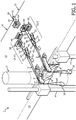
- Device 1 for erecting a monopile 2 of a wind turbine is shown.
- Device 1 comprises a jack-up platform 10 provided with spud poles 11 at its four corners, and a work deck 12.
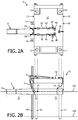
- the platform 10 is stabilized by lowering the spud poles 11 until they take support onto or into the seabed 100.
- the work deck 12 may in this stabilized position be raised above sea level 101 by jacking it upwards along the spud poles 11, as shown in figure 2B for instance.
- To work deck 12 are connected a pair of first and second fixation means (3, 4) for a tension cable 5, as well as guiding means for tension cable 5 in the form of a hoist bracket 6.
- Hoist bracket 6 extends over an edge 13 of work deck 12 and is provided with a sheave 7. Hoist bracket 6 is supported by member 8, which is connected to and supported by the side 13. A second pair of first and second fixation means (3', 4') for a second tension cable 5' are also connected to work deck 12, as well as guiding means for tension cable 5' in the form of a hoist bracket 6'. As with hoist bracket 6, hoist bracket 6' extends over an edge 13 of work deck 12 and is provided with a sheave 7'. Hoist bracket 6' is supported by member 8', which is connected to and supported by the side 13.
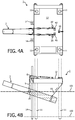
- the first fixation means 3 comprise a winch 30 and a compound pulley, which is a combination of a fixed pulley 31 and a movable pulley 32.
- Fixed pulley 31 is connected to work deck 12, while movable pulley 32 is trailing.
- Compound pulley (31, 32) is a block and tackle, i.e. comprises several sheaves mounted on each axle or one sheave with several grooves.
- a tension cable 35 is at one end attached to fixed pulley 31, runs to the movable pulley 32, is wound around its sheave and returns to fixed pulley 31 where it is wound around its sheave before running to the movable pulley again. This loop is repeated a desired number of times before tension cable 35 is led to winch 30 where it is wound up.
- the tension cable 5 is attached to the first fixation means 3 by a shackle 33, connected to movable pulley 32, is guided along the sheave 7 of hoist bracket 6 and around attachment means in the form of bollard 20, that is welded on the monopile 2, and led back along the sheave 7 of hoist bracket 6 to the second fixation means 4 to form a sling.
- the second fixation means 4 comprise similar components as the first fixation means 3 and their description will not be repeated here.
- the sling formed by tension cable 5 can be shortened (thereby pulling on bollard 20) or lengthened (thereby lowering bollard 20) by winding up or winding down the cable 35 with the aid of winch 30.
- a tension cable 5' is attached to the first fixation means 3' by a shackle 33', connected to movable pulley 32', is guided along the sheave 7' of hoist bracket 6' and around attachment means in the form of bollard 20', that is welded on the monopile 2, and led back along the sheave 7' of hoist bracket 6' to the second fixation means 4' to form a sling.
- the sling formed by tension cable 5' can be shortened (thereby pulling on bollard 20') or lengthened (thereby lowering bollard 20') by winding up or winding down the cable 35' with the aid of winch 30'.
- platform 10 comprises additional spud poles (14, 14') that are arranged at the edge 13 of work deck 12 on both sides of hoist brackets (6, 6') and in proximity thereof. Additional spud poles (14, 14') that take support onto or into the sea bed, prevent the platform 10 from tilting to an undesirable level during operations.
- further fixation means in the form of a winch 50 that is able to wind up or wind down a further tension cable 55.
- Tension cable 55 is guided along further guiding means in the form of a hoist bracket 51 with sheave 52, provided at an edge 15 opposite the edge 13. In operation, tension cable 55 is attached to the monopile 2 at a rear end thereof.
- the method comprises providing a device as has been described in detail above.
- the platform 1 is first put in a jacked-up position by lowering the spud poles 11 until they take support into or onto the seabed 100, and then raising the work deck 12 with respect to the spud poles 11 until the desired height of the work deck is reached. Work deck is then above sea level 101.
- a monopile 2 which has been transported from the shore to the off-shore platform 1 by closing off its two open ends with closure caps of steel or another suitable material such that it is able to float in the water in a substantially horizontal position, is then brought at least partly underneath the work deck 12 of platform 1 in this substantially horizontal floating condition.
- a top end part 21 of monopile 2 is brought more or less underneath the edge 13 between the brackets (6, 6') and a rear end 22 thereof more or less underneath the edge 15 of bracket 51. With the monopile 2 in this position, the slings formed by tension cable 5 and 5' are slung around the bollards 20 and 20' respectively, and the rear cable 55 is likewise attached to the rear end 22, for instance by forming a loop.
- Bollards (20, 20') on monopile 2 are located between the top end 23 of monopile 2 and its center of gravity 24, and more preferably relatively close to the center of gravity 24. In this position, the two closure caps are then removed which allows the monopile 2 to fill with water.
- the tension cables 5 and 55 are then straightened by winding up cables (35, 45, 35', 45') on winches (30, 40, 30', 40'), and cable 55 on winch 50.
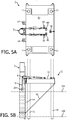
- the monopile 2 is then pulled in an erected position ( figure 5 ) along the edge 13 of work deck 12, in which it gradually fills up with water.
- the rear cable 55 is gradually lengthened.
- the monopile 2 is driven into the seabed under the action of a hydraulic hammer 25, known per se in the art. If desired a hydraulic hammer 25 with follower may be used.
- a transition piece is fitted onto the monopile and the annulus between the monopole and transition piece is grouted making an extremely strong connection.
- a tower of for instance a wind turbine may then be put onto the transition piece, according to known methods.
- the fixation means and the further fixation means comprise linear winches (70, 80, 70', 80') and 90.
- the components of a linear winch will be described by reference to linear winch 70 onloy but it is to be understood that linear winches 70', 80, 80' and 90 have similar components.
- Linear winch 70 comprises a steel frame 71 designed to withstand a rated load and attached firmly to work deck 12 by bollard 74 and cable 75.
- Linear winch 70 comprises two cable grips 72 and 73, which are guided by runners on the frame 71 and may be moved along the longitudinal direction of the frame by two hydraulic cylinders (not shown). The two cable grips 72 and 73 catch the tension cable 5 intermittently thereby allowing to pull or pay out cable 5, as desired.
- a hydraulic power unit (not shown) is used to power the linear winch.
- the method and device according to the invention allow the provision of a monopile foundation in an efficient manner, obviating the need for large cranes on the platform, and requiring less time than the known method.
- the method is less dependent on weather conditions moreover.
Landscapes
- Engineering & Computer Science (AREA)
- General Engineering & Computer Science (AREA)
- Mechanical Engineering (AREA)
- Life Sciences & Earth Sciences (AREA)
- Structural Engineering (AREA)
- Civil Engineering (AREA)
- Sustainable Energy (AREA)
- Combustion & Propulsion (AREA)
- Chemical & Material Sciences (AREA)
- Sustainable Development (AREA)
- General Life Sciences & Earth Sciences (AREA)
- Mining & Mineral Resources (AREA)
- Paleontology (AREA)
- Wind Motors (AREA)
- Foundations (AREA)
Claims (15)
- Einheit (1) zum Errichten eines großen schlanken Körpers auf See, beispielsweise eines Monopiles (2) einer Windturbine, wobei die Einheit eine Hubinsel (10) umfasst, die mit Ankerpfählen (11) zur Befestigung in einem Unterwasserboden (100) und einem Arbeitsdeck (12) bereitgestellt werden, an denen Befestigungsmittel (3, 4, 3', 4') für ein Spannseil (5, 5') und ein Führungsmittel (6, 7, 6', 7') angebracht sind, die an einem Rand des Arbeitsdecks (12) bereitgestellt werden, wobei das Befestigungsmittel (3, 4, 3', 4') und das Führungsmittel (6, 7, 6', 7') auf Höhe des Arbeitsdecks bereitgestellt werden, wodurch im Betrieb das Spannseil (5, 5') mit dem Befestigungsmittel (3, 4, 3', 4') verbunden, entlang des Führungsmittels (6, 7, 6', 7') geführt und am großen schlanken Körper befestigt ist, wobei am Arbeitsdeck (12) ein weiteres Befestigungsmittel (50) für ein weiteres Spannseil (55) und ein weiteres Führungsmittel (51, 52) angebracht sind, die an einem Rand (15) gegenüber dem Rand (13) des Führungsmittels (6, 7, 6', 7') bereitgestellt werden, wobei das weitere Befestigungsmittel (50) und das weitere Führungsmittel (51, 52) auf Höhe des Arbeitsdecks bereitgestellt werden, wodurch im Betrieb das weitere Spannseil (55) an einem hinteren Ende (22) davon mit dem großen schlanken Körper verbunden ist, wobei das weitere Befestigungsmittel (50) so angepasst ist, dass es das weitere Spannseil (55) verlängert oder verkürzt,
wobei sich die Verbindungsmittel (20) des großen schlanken Körpers (2) zwischen dem oberen Ende davon und seinem Schwerpunkt (24) befinden, wobei das Befestigungsmittel (3, 4, 3', 4') so angepasst ist, dass es das weitere Spannseil (5, 5') verkürzt und dadurch den großen schlanken Körper (2) entlang des Randes des Arbeitsdecks (12) schrittweise in eine aufrechte Position bringt. - Einheit nach Anspruch 1, wobei das Befestigungsmittel ein erstes und ein zweites Befestigungsmittel umfasst, wodurch im Betrieb das Spannseil mit dem ersten Befestigungsmittel verbunden wird, entlang des Führungsmittels und um das Verbindungsmittel geführt wird, das auf dem großen schlanken Körper bereitgestellt und entlang des Führungsmittels zum zweiten Befestigungsmittel zurückgeführt wird und so eine Schlinge bildet, wobei das Befestigungsmittel so angepasst ist, das es die Schlinge verlängert oder verkürzt.
- Einheit nach Anspruch 2, wobei die Einheit zwei Paare erste und zweite Befestigungsmittel und zwei Spannseile umfasst.
- Einheit nach einem der vorstehenden Ansprüche, wobei das Befestigungsmittel und/oder das weitere Befestigungsmittel Winden, vorzugsweise lineare Winden, umfassen.
- Einheit nach einem der vorstehenden Ansprüche, wobei das Befestigungsmittel und/oder das weitere Befestigungsmittel eine bewegliche Rolle umfasst.
- Einheit nach einem der vorstehenden Ansprüche, wobei das Befestigungsmittel und/oder das weitere Befestigungsmittel eine Rollengruppe, d.h. eine Kombination aus fester und beweglicher Rolle, umfassen.
- Einheit nach Anspruch 6, wobei die Rollengruppe einen Flaschenzug umfasst.
- Einheit nach einem der vorstehenden Ansprüche, wobei das Führungsmittel einen Hubarm umfasst, der sich über den Rand des Arbeitsdecks erstreckt und mit einer Umlenkrolle bereitgestellt wird.
- Einheit nach einem der vorstehenden Ansprüche, wobei die Plattform zusätzliche Ankerpfähle umfasst, die am Rand des Arbeitsdecks auf beiden Seiten der Führungsmittel und in deren Nähe angeordnet sind.
- Verfahren zum Errichten eines großen schlanken Körpers auf See, beispielsweise eines Monopiles einer Windturbine, wobei das Verfahren Folgendes umfasst:- das Bereitstellen einer Einheit nach einem der vorstehenden Ansprüche;- mit der Plattform in angehobener Position das Bringen des großen schlanken Körpers in einen im Wesentlichen horizontalen schwimmenden Zustand mindestens teilweise unterhalb des Arbeitsdecks der Plattform, so dass ein oberes Ende davon unterhalb des Randes des Führungsmittels und ein hinteres Ende davon unterhalb des Randes des weiteren Führungsmittels liegt;- das Verbinden des Spannseils mit dem Befestigungsmittel und dem schlanken Körper, in dem sich Verbindungsmittel des großen schlanken Körpers zwischen dem oberen Ende davon und seinem Schwerpunkt befinden; und- das Verbinden eines weiteren Spannseils mit dem großen schlanken Körper am hinteren Ende davon; und- dadurch das Ziehen am Spannseil mit dem Befestigungsmittel;- das schrittweise Bringen des großen schlanken Körpers entlang des Randes des Arbeitsdecks in eine aufrechte Position; und optional- das Treiben des schlanken Körpers in den Unterwasserboden.
- Verfahren nach Anspruch 10, wobei das Befestigungsmittel ein erstes und ein zweites Befestigungsmittel umfasst, wodurch das Spannseil mit dem ersten Befestigungsmittel verbunden wird, entlang des Führungsmittels und um das Verbindungsmittel geführt wird, das auf dem großen schlanken Körper bereitgestellt und entlang des Führungsmittels zum zweiten Befestigungsmittel zurückgeführt wird und so eine Schlinge bildet.
- Verfahren nach Anspruch 11, wobei die Einheit zwei Paare erste und zweite Befestigungsmittel und zwei Spannseile umfasst, von denen jedes mit dem ersten Befestigungsmittel eines Paars verbunden, entlang des Führungsmittels und um das Verbindungsmittel geführt wird, das auf dem großen schlanken Körper bereitgestellt und entlang des Führungsmittels zum zweiten Befestigungsmittel eines Paars zurückgeführt wird und so eine Schlinge bildet.
- Verfahren nach einem der vorstehenden Ansprüche 10-12, wobei sich das Verbindungsmittel des großen schlanken Körpers relativ nah an seinem Schwerpunkt befindet.
- Verfahren nach einem der vorstehenden Ansprüche 10-13, wobei der schlanke Körper ein Monopile einer Windturbine ist und mit einem Hydraulikhammer in das Substrat getrieben wird.
- Verfahren zur Aufstellung einer in die Höhe gerichteten Masse, beispielsweise einer Windturbine auf einem Monopile, wobei das Verfahren die Verfahrensschritte nach einem der vorstehenden Ansprüche 10-14 und den Schritt des Befestigens der Windturbine am aufgerichteten Monopile umfasst.
Priority Applications (5)
| Application Number | Priority Date | Filing Date | Title |
|---|---|---|---|
| EP10158186.6A EP2372143B1 (de) | 2010-03-29 | 2010-03-29 | Vorrichtung und Verfahren zum Aufrichten auf See eines schlanken Körpers wie eines Einzelpfeilers einer Windturbine |
| DK10158186.6T DK2372143T3 (en) | 2010-03-29 | 2010-03-29 | EQUIPMENT AND PROCEDURE TO RISE A LARGE SLIM BODY ON THE SEA, LIKE A MONOPOLY FOR A WIND TURBINE |
| PL10158186T PL2372143T3 (pl) | 2010-03-29 | 2010-03-29 | Urządzenie i sposób wznoszenia na morzu dużego smukłego korpusu, takiego jak monopal turbiny wiatrowej |
| AU2011201391A AU2011201391B2 (en) | 2010-03-29 | 2011-03-25 | Device and method for erecting at sea a large slender body, such as the monopile of a wind turbine |
| US13/074,810 US8911178B2 (en) | 2010-03-29 | 2011-03-29 | Device and method for erecting at sea a large slender body, such as the monopile of a wind turbine |
Applications Claiming Priority (1)
| Application Number | Priority Date | Filing Date | Title |
|---|---|---|---|
| EP10158186.6A EP2372143B1 (de) | 2010-03-29 | 2010-03-29 | Vorrichtung und Verfahren zum Aufrichten auf See eines schlanken Körpers wie eines Einzelpfeilers einer Windturbine |
Publications (2)
| Publication Number | Publication Date |
|---|---|
| EP2372143A1 EP2372143A1 (de) | 2011-10-05 |
| EP2372143B1 true EP2372143B1 (de) | 2018-06-20 |
Family
ID=42642127
Family Applications (1)
| Application Number | Title | Priority Date | Filing Date |
|---|---|---|---|
| EP10158186.6A Active EP2372143B1 (de) | 2010-03-29 | 2010-03-29 | Vorrichtung und Verfahren zum Aufrichten auf See eines schlanken Körpers wie eines Einzelpfeilers einer Windturbine |
Country Status (5)
| Country | Link |
|---|---|
| US (1) | US8911178B2 (de) |
| EP (1) | EP2372143B1 (de) |
| AU (1) | AU2011201391B2 (de) |
| DK (1) | DK2372143T3 (de) |
| PL (1) | PL2372143T3 (de) |
Families Citing this family (20)
| Publication number | Priority date | Publication date | Assignee | Title |
|---|---|---|---|---|
| FR3002557B1 (fr) * | 2013-02-27 | 2015-04-17 | Technip France | Procede de mise en place d'un element allonge dans une etendue d'eau, dispositif et installation associes |
| NL2011985C2 (en) * | 2013-12-19 | 2015-06-22 | Ihc Norex B V | Saddle and hook system. |
| NL2012527B1 (en) * | 2014-03-28 | 2016-02-10 | Bluemarine Offshore Yard Service Bv | Method for lowering a subsea structure having a substantially flat support base into the water through the splash zone. |
| NO340970B1 (en) * | 2015-05-07 | 2017-07-31 | Scana Offshore Vestby As | Mooring arrangement |
| EP3356278B2 (de) * | 2015-10-01 | 2023-11-08 | Vestas Wind Systems A/S | Hebeanordnung zum anheben einer windturbinenkomponente |
| NL2018328B1 (en) * | 2017-02-07 | 2018-09-21 | Seaway Heavy Lifting Eng B V | Upending device for upending an elongate support structure |
| GB2560006A (en) * | 2017-02-24 | 2018-08-29 | Statoil Petroleum As | Installation of mono-pile |
| EP3487018A1 (de) | 2017-11-15 | 2019-05-22 | Siemens Gamesa Renewable Energy A/S | Offshore-struktur und verfahren zur befestigung einer röhre oder eines kabels an einem gerät einer offshore-struktur |
| US10544015B1 (en) * | 2018-07-10 | 2020-01-28 | GeoSea N.V. | Device and method for lifting an object from a deck of a vessel subject to movements |
| CN108894227A (zh) * | 2018-07-20 | 2018-11-27 | 大连理工大学 | 一种横摇补偿式的海洋风电单桩基础抱紧扶正装置 |
| KR20220016800A (ko) * | 2019-01-21 | 2022-02-10 | 아이티알이씨 비. 브이. | 파일 드라이빙 방법 및 파일 드라이빙 시스템 |
| NL2023210B1 (en) * | 2019-03-28 | 2020-10-06 | Itrec Bv | Pile driving method and system for driving a pile. |
| CN109869279B (zh) * | 2019-03-29 | 2020-01-07 | 浙江海洋大学 | 一种海上风电机安装方法及安装系统 |
| NL2022947B1 (en) * | 2019-04-15 | 2020-10-22 | Itrec Bv | A vessel and method for installation of a pile adapted to support an offshore wind turbine |
| CN110217698B (zh) * | 2019-07-01 | 2024-04-30 | 风潮海洋工程(深圳)有限公司 | 一种海上风电大直径单桩翻转工装及翻转方法 |
| GB2592595B (en) | 2020-03-02 | 2023-04-05 | Seaway 7 Eng B V | Upending elongate structures offshore |
| WO2021245236A1 (en) * | 2020-06-05 | 2021-12-09 | Macgregor Norway As | Pile handling facility |
| IT202000017887A1 (it) | 2020-07-23 | 2022-01-23 | Saipem Spa | Metodo e gruppo galleggiante per installare pali di fondazione in un letto di un corpo d'acqua |
| KR102495454B1 (ko) * | 2021-04-30 | 2023-02-06 | 주식회사 케이엘테크놀로지 | 해상 풍력발전기 설치용 크레인 |
| CN113404049A (zh) * | 2021-08-03 | 2021-09-17 | 中国港湾工程有限责任公司 | 海上平台桩基施工方法 |
Citations (1)
| Publication number | Priority date | Publication date | Assignee | Title |
|---|---|---|---|---|
| US4722640A (en) * | 1978-05-30 | 1988-02-02 | Letourneau Richard L | Slant leg offshore platform and method of operating same |
Family Cites Families (14)
| Publication number | Priority date | Publication date | Assignee | Title |
|---|---|---|---|---|
| US2924047A (en) | 1960-02-09 | machovec | ||
| US2924947A (en) * | 1955-01-07 | 1960-02-16 | Peterson Ole | Caisson |
| US3036438A (en) * | 1958-04-04 | 1962-05-29 | Jersey Prod Res Co | Caisson with float releasably attached |
| US3433024A (en) * | 1966-03-31 | 1969-03-18 | Mobil Oil Corp | Versatile marine structure |
| FR1597014A (de) * | 1967-12-28 | 1970-06-22 | ||
| US3511057A (en) * | 1968-10-14 | 1970-05-12 | Strabag Bau Ag | Erection and construction of multispan bridges and piers |
| US3805534A (en) * | 1972-05-09 | 1974-04-23 | Shell Oil Co | Slide resistant platform anchor conductor silo |
| NO771673L (no) * | 1976-05-20 | 1977-11-22 | Pool Co | Fast offshore-plattform samt fremgangsm}te ved oppstilling av samme |
| US4293239A (en) * | 1979-04-02 | 1981-10-06 | Odeco Engineers Inc. | Method of erecting a very large diameter offshore column |
| BR8600226A (pt) * | 1985-01-29 | 1986-09-30 | Exxon Production Research Co | Processo e aparelho para instalar uma estrutura maritima em um local e aparelho para instalar uma camisa de plataforma maritima |
| EP0945338A1 (de) * | 1998-03-25 | 1999-09-29 | OEDC (Offshore Energy Development Corporation) | Konstruktionsverfahren für Spierentonnen |
| FR2876123B1 (fr) * | 2004-10-04 | 2008-02-08 | Technip France Sa | Procede d'installation des jambes sur un pont d'une plate-forme d'exploitation en mer. |
| GB0618885D0 (en) * | 2006-09-26 | 2006-11-01 | Seacore Ltd | Improvements in and relating to pile or column installation |
| DE202009006507U1 (de) * | 2009-04-30 | 2009-08-06 | Bard Engineering Gmbh | Führungsgestell zum vertikalen Führen von mindestens einem Fundamentpfahl beim Errichten eines Fundaments einer Offshore-Windenergieanlage und Stapel-, Aufricht- und Absenkvorrichtung zum Errichten eines Fundaments einer Offshore-Windenergieanlage |
-
2010
- 2010-03-29 EP EP10158186.6A patent/EP2372143B1/de active Active
- 2010-03-29 PL PL10158186T patent/PL2372143T3/pl unknown
- 2010-03-29 DK DK10158186.6T patent/DK2372143T3/en active
-
2011
- 2011-03-25 AU AU2011201391A patent/AU2011201391B2/en active Active
- 2011-03-29 US US13/074,810 patent/US8911178B2/en active Active
Patent Citations (1)
| Publication number | Priority date | Publication date | Assignee | Title |
|---|---|---|---|---|
| US4722640A (en) * | 1978-05-30 | 1988-02-02 | Letourneau Richard L | Slant leg offshore platform and method of operating same |
Also Published As
| Publication number | Publication date |
|---|---|
| US20110258829A1 (en) | 2011-10-27 |
| AU2011201391B2 (en) | 2016-03-17 |
| PL2372143T3 (pl) | 2019-01-31 |
| US8911178B2 (en) | 2014-12-16 |
| EP2372143A1 (de) | 2011-10-05 |
| DK2372143T3 (en) | 2018-10-01 |
| AU2011201391A1 (en) | 2011-10-13 |
Similar Documents
| Publication | Publication Date | Title |
|---|---|---|
| EP2372143B1 (de) | Vorrichtung und Verfahren zum Aufrichten auf See eines schlanken Körpers wie eines Einzelpfeilers einer Windturbine | |
| DK2124485T3 (en) | Advanced processing based on a complex exponential modulated filter bank and adaptive time signaling methods | |
| JP6039097B2 (ja) | 浮遊輸送および設置構造体、および浮遊風力タービン | |
| US8657534B2 (en) | Floating platform with improved anchoring | |
| EP2641825B1 (de) | Schiff zur installation von offshore-windkraftanlagen und verfahren zur installation von offshore-windkraftanlagen damit | |
| EP1356205B1 (de) | Verfahren und vorrichtung zur anordnung mindestens einer windturbine an offenem wasser | |
| KR20120047740A (ko) | 갑판승강식작업대선 및 이를 이용한 해상풍력발전시설의 시공방법 | |
| WO2003066427A1 (en) | Vessel for installation of erect structures | |
| EP2952633B1 (de) | Verfahren zur installation eines offshore-windturbinenturms mit auf pfählen gestüztem fundament und vorrichtung zur implementierung des besagten verfahrens | |
| KR20170118709A (ko) | 부유식 풍력 터빈 플랫폼을 건설, 조립 및 진수하는 방법 | |
| KR20130059397A (ko) | 부체 구조물 작업 시스템, 부체 구조물, 작업선 및 부체 구조물 작업 방법 | |
| US9022691B2 (en) | Method of installing an offshore wind turbine and a transport vessel thereof | |
| CN114715336B (zh) | 适用于深水的海上风电筒型基础运输安装一体化船舶及安装方法 | |
| EP4114781A1 (de) | Kranschiff zum heben einer offshore-windturbine oder komponente davon | |
| WO2011102738A2 (en) | A method and vessel for offshore transport and installation of windmill assemblies | |
| CN210917364U (zh) | 一种用于起重船上的钢管桩定位平台 | |
| EP3260604A1 (de) | Oberteil einer tragkonstruktion | |
| JP7451674B2 (ja) | 洋上風力タービンのための浮体基礎、風からエネルギーを抽出するためのシステム、および風力タービンを取り付ける方法 | |
| WO2014097254A1 (en) | Device and method for placing a structural component | |
| CN110130348B (zh) | 一种大直径浮式联合抱桩系统及其施工方法 | |
| KR101383287B1 (ko) | 해상기둥구조물에서의 중량물 이송방법 및 이를 위한 중량물 이송장치 | |
| CN208472750U (zh) | 导管架基础施工装置 | |
| EP3857062A1 (de) | Verfahren zur installation einer offshore-windenergieanlage und unterbau für offshore-windenergieanlage | |
| EP3889029B1 (de) | Vorrichtung zum anheben und platzieren eines länglichen gegenstandes auf eine bodenfläche und entsprechendes verfahren | |
| NO20221228A1 (en) | A floating foundation for an offshore wind turbine, a system for extracting energy from wind, and a method of installing a wind turbine |
Legal Events
| Date | Code | Title | Description |
|---|---|---|---|
| PUAI | Public reference made under article 153(3) epc to a published international application that has entered the european phase |
Free format text: ORIGINAL CODE: 0009012 |
|
| AK | Designated contracting states |
Kind code of ref document: A1 Designated state(s): AT BE BG CH CY CZ DE DK EE ES FI FR GB GR HR HU IE IS IT LI LT LU LV MC MK MT NL NO PL PT RO SE SI SK SM TR |
|
| 17P | Request for examination filed |
Effective date: 20120405 |
|
| 17Q | First examination report despatched |
Effective date: 20160811 |
|
| STAA | Information on the status of an ep patent application or granted ep patent |
Free format text: STATUS: EXAMINATION IS IN PROGRESS |
|
| REG | Reference to a national code |
Ref country code: DE Ref legal event code: R079 Ref document number: 602010051374 Country of ref document: DE Free format text: PREVIOUS MAIN CLASS: F03D0001000000 Ipc: E02B0017020000 |
|
| GRAP | Despatch of communication of intention to grant a patent |
Free format text: ORIGINAL CODE: EPIDOSNIGR1 |
|
| STAA | Information on the status of an ep patent application or granted ep patent |
Free format text: STATUS: GRANT OF PATENT IS INTENDED |
|
| RIC1 | Information provided on ipc code assigned before grant |
Ipc: F03D 13/20 20160101ALI20171221BHEP Ipc: E02D 27/42 20060101ALI20171221BHEP Ipc: E02B 17/02 20060101AFI20171221BHEP Ipc: E02B 17/00 20060101ALI20171221BHEP Ipc: F03D 13/10 20160101ALI20171221BHEP |
|
| INTG | Intention to grant announced |
Effective date: 20180111 |
|
| GRAS | Grant fee paid |
Free format text: ORIGINAL CODE: EPIDOSNIGR3 |
|
| GRAA | (expected) grant |
Free format text: ORIGINAL CODE: 0009210 |
|
| STAA | Information on the status of an ep patent application or granted ep patent |
Free format text: STATUS: THE PATENT HAS BEEN GRANTED |
|
| AK | Designated contracting states |
Kind code of ref document: B1 Designated state(s): AT BE BG CH CY CZ DE DK EE ES FI FR GB GR HR HU IE IS IT LI LT LU LV MC MK MT NL NO PL PT RO SE SI SK SM TR |
|
| REG | Reference to a national code |
Ref country code: GB Ref legal event code: FG4D |
|
| REG | Reference to a national code |
Ref country code: IE Ref legal event code: FG4D |
|
| REG | Reference to a national code |
Ref country code: AT Ref legal event code: REF Ref document number: 1010694 Country of ref document: AT Kind code of ref document: T Effective date: 20180715 |
|
| REG | Reference to a national code |
Ref country code: DE Ref legal event code: R096 Ref document number: 602010051374 Country of ref document: DE |
|
| REG | Reference to a national code |
Ref country code: DK Ref legal event code: T3 Effective date: 20180924 |
|
| REG | Reference to a national code |
Ref country code: NL Ref legal event code: FP |
|
| REG | Reference to a national code |
Ref country code: SE Ref legal event code: TRGR |
|
| PG25 | Lapsed in a contracting state [announced via postgrant information from national office to epo] |
Ref country code: LT Free format text: LAPSE BECAUSE OF FAILURE TO SUBMIT A TRANSLATION OF THE DESCRIPTION OR TO PAY THE FEE WITHIN THE PRESCRIBED TIME-LIMIT Effective date: 20180620 Ref country code: NO Free format text: LAPSE BECAUSE OF FAILURE TO SUBMIT A TRANSLATION OF THE DESCRIPTION OR TO PAY THE FEE WITHIN THE PRESCRIBED TIME-LIMIT Effective date: 20180920 Ref country code: BG Free format text: LAPSE BECAUSE OF FAILURE TO SUBMIT A TRANSLATION OF THE DESCRIPTION OR TO PAY THE FEE WITHIN THE PRESCRIBED TIME-LIMIT Effective date: 20180920 Ref country code: FI Free format text: LAPSE BECAUSE OF FAILURE TO SUBMIT A TRANSLATION OF THE DESCRIPTION OR TO PAY THE FEE WITHIN THE PRESCRIBED TIME-LIMIT Effective date: 20180620 |
|
| REG | Reference to a national code |
Ref country code: LT Ref legal event code: MG4D |
|
| PG25 | Lapsed in a contracting state [announced via postgrant information from national office to epo] |
Ref country code: LV Free format text: LAPSE BECAUSE OF FAILURE TO SUBMIT A TRANSLATION OF THE DESCRIPTION OR TO PAY THE FEE WITHIN THE PRESCRIBED TIME-LIMIT Effective date: 20180620 Ref country code: HR Free format text: LAPSE BECAUSE OF FAILURE TO SUBMIT A TRANSLATION OF THE DESCRIPTION OR TO PAY THE FEE WITHIN THE PRESCRIBED TIME-LIMIT Effective date: 20180620 Ref country code: GR Free format text: LAPSE BECAUSE OF FAILURE TO SUBMIT A TRANSLATION OF THE DESCRIPTION OR TO PAY THE FEE WITHIN THE PRESCRIBED TIME-LIMIT Effective date: 20180921 |
|
| REG | Reference to a national code |
Ref country code: AT Ref legal event code: MK05 Ref document number: 1010694 Country of ref document: AT Kind code of ref document: T Effective date: 20180620 |
|
| PG25 | Lapsed in a contracting state [announced via postgrant information from national office to epo] |
Ref country code: EE Free format text: LAPSE BECAUSE OF FAILURE TO SUBMIT A TRANSLATION OF THE DESCRIPTION OR TO PAY THE FEE WITHIN THE PRESCRIBED TIME-LIMIT Effective date: 20180620 Ref country code: IS Free format text: LAPSE BECAUSE OF FAILURE TO SUBMIT A TRANSLATION OF THE DESCRIPTION OR TO PAY THE FEE WITHIN THE PRESCRIBED TIME-LIMIT Effective date: 20181020 Ref country code: RO Free format text: LAPSE BECAUSE OF FAILURE TO SUBMIT A TRANSLATION OF THE DESCRIPTION OR TO PAY THE FEE WITHIN THE PRESCRIBED TIME-LIMIT Effective date: 20180620 Ref country code: AT Free format text: LAPSE BECAUSE OF FAILURE TO SUBMIT A TRANSLATION OF THE DESCRIPTION OR TO PAY THE FEE WITHIN THE PRESCRIBED TIME-LIMIT Effective date: 20180620 Ref country code: CZ Free format text: LAPSE BECAUSE OF FAILURE TO SUBMIT A TRANSLATION OF THE DESCRIPTION OR TO PAY THE FEE WITHIN THE PRESCRIBED TIME-LIMIT Effective date: 20180620 Ref country code: SK Free format text: LAPSE BECAUSE OF FAILURE TO SUBMIT A TRANSLATION OF THE DESCRIPTION OR TO PAY THE FEE WITHIN THE PRESCRIBED TIME-LIMIT Effective date: 20180620 |
|
| REG | Reference to a national code |
Ref country code: CH Ref legal event code: PK Free format text: BERICHTIGUNGEN |
|
| RIC2 | Information provided on ipc code assigned after grant |
Ipc: F03D 13/10 20160101ALI20171221BHEP Ipc: F03D 13/20 20160101ALI20171221BHEP Ipc: E02B 17/00 20060101ALI20171221BHEP Ipc: E02B 17/02 20060101AFI20171221BHEP Ipc: E02D 27/42 20060101ALI20171221BHEP |
|
| PG25 | Lapsed in a contracting state [announced via postgrant information from national office to epo] |
Ref country code: SM Free format text: LAPSE BECAUSE OF FAILURE TO SUBMIT A TRANSLATION OF THE DESCRIPTION OR TO PAY THE FEE WITHIN THE PRESCRIBED TIME-LIMIT Effective date: 20180620 Ref country code: IT Free format text: LAPSE BECAUSE OF FAILURE TO SUBMIT A TRANSLATION OF THE DESCRIPTION OR TO PAY THE FEE WITHIN THE PRESCRIBED TIME-LIMIT Effective date: 20180620 Ref country code: ES Free format text: LAPSE BECAUSE OF FAILURE TO SUBMIT A TRANSLATION OF THE DESCRIPTION OR TO PAY THE FEE WITHIN THE PRESCRIBED TIME-LIMIT Effective date: 20180620 |
|
| REG | Reference to a national code |
Ref country code: DE Ref legal event code: R097 Ref document number: 602010051374 Country of ref document: DE |
|
| PLBE | No opposition filed within time limit |
Free format text: ORIGINAL CODE: 0009261 |
|
| STAA | Information on the status of an ep patent application or granted ep patent |
Free format text: STATUS: NO OPPOSITION FILED WITHIN TIME LIMIT |
|
| 26N | No opposition filed |
Effective date: 20190321 |
|
| PG25 | Lapsed in a contracting state [announced via postgrant information from national office to epo] |
Ref country code: SI Free format text: LAPSE BECAUSE OF FAILURE TO SUBMIT A TRANSLATION OF THE DESCRIPTION OR TO PAY THE FEE WITHIN THE PRESCRIBED TIME-LIMIT Effective date: 20180620 |
|
| PG25 | Lapsed in a contracting state [announced via postgrant information from national office to epo] |
Ref country code: MC Free format text: LAPSE BECAUSE OF FAILURE TO SUBMIT A TRANSLATION OF THE DESCRIPTION OR TO PAY THE FEE WITHIN THE PRESCRIBED TIME-LIMIT Effective date: 20180620 |
|
| REG | Reference to a national code |
Ref country code: CH Ref legal event code: PL |
|
| PG25 | Lapsed in a contracting state [announced via postgrant information from national office to epo] |
Ref country code: LU Free format text: LAPSE BECAUSE OF NON-PAYMENT OF DUE FEES Effective date: 20190329 |
|
| PG25 | Lapsed in a contracting state [announced via postgrant information from national office to epo] |
Ref country code: CH Free format text: LAPSE BECAUSE OF NON-PAYMENT OF DUE FEES Effective date: 20190331 Ref country code: LI Free format text: LAPSE BECAUSE OF NON-PAYMENT OF DUE FEES Effective date: 20190331 Ref country code: IE Free format text: LAPSE BECAUSE OF NON-PAYMENT OF DUE FEES Effective date: 20190329 |
|
| REG | Reference to a national code |
Ref country code: DE Ref legal event code: R081 Ref document number: 602010051374 Country of ref document: DE Owner name: DEME OFFSHORE BE NV, BE Free format text: FORMER OWNER: GEOSEA NV, ZWIJNDRECHT, BE |
|
| PG25 | Lapsed in a contracting state [announced via postgrant information from national office to epo] |
Ref country code: TR Free format text: LAPSE BECAUSE OF FAILURE TO SUBMIT A TRANSLATION OF THE DESCRIPTION OR TO PAY THE FEE WITHIN THE PRESCRIBED TIME-LIMIT Effective date: 20180620 |
|
| REG | Reference to a national code |
Ref country code: GB Ref legal event code: 732E Free format text: REGISTERED BETWEEN 20200305 AND 20200311 |
|
| PG25 | Lapsed in a contracting state [announced via postgrant information from national office to epo] |
Ref country code: MT Free format text: LAPSE BECAUSE OF NON-PAYMENT OF DUE FEES Effective date: 20190329 Ref country code: PT Free format text: LAPSE BECAUSE OF FAILURE TO SUBMIT A TRANSLATION OF THE DESCRIPTION OR TO PAY THE FEE WITHIN THE PRESCRIBED TIME-LIMIT Effective date: 20181022 |
|
| REG | Reference to a national code |
Ref country code: NL Ref legal event code: HC Owner name: DEME OFFSHORE HOLDING N.V.; NL Free format text: DETAILS ASSIGNMENT: CHANGE OF OWNER(S), CHANGE OF OWNER(S) NAME; FORMER OWNER NAME: GEOSEA NV Effective date: 20200612 Ref country code: NL Ref legal event code: PD Owner name: DEME OFFSHORE BE N.V.; BE Free format text: DETAILS ASSIGNMENT: CHANGE OF OWNER(S), ASSIGNMENT; FORMER OWNER NAME: DEME OFFSHORE HOLDING N.V. Effective date: 20200612 |
|
| REG | Reference to a national code |
Ref country code: BE Ref legal event code: HC Owner name: DEME OFFSHORE HOLDING N.V.; BE Free format text: DETAILS ASSIGNMENT: CHANGE OF OWNER(S), CHANGEMENT DE NOM DU PROPRIETAIRE; FORMER OWNER NAME: GEOSEA NV Effective date: 20200514 Ref country code: BE Ref legal event code: PD Owner name: DEME OFFSHORE BE N.V.; BE Free format text: DETAILS ASSIGNMENT: CHANGE OF OWNER(S), CESSION; FORMER OWNER NAME: DEME OFFSHORE HOLDING N.V. Effective date: 20200514 |
|
| PG25 | Lapsed in a contracting state [announced via postgrant information from national office to epo] |
Ref country code: CY Free format text: LAPSE BECAUSE OF FAILURE TO SUBMIT A TRANSLATION OF THE DESCRIPTION OR TO PAY THE FEE WITHIN THE PRESCRIBED TIME-LIMIT Effective date: 20180620 |
|
| PG25 | Lapsed in a contracting state [announced via postgrant information from national office to epo] |
Ref country code: HU Free format text: LAPSE BECAUSE OF FAILURE TO SUBMIT A TRANSLATION OF THE DESCRIPTION OR TO PAY THE FEE WITHIN THE PRESCRIBED TIME-LIMIT; INVALID AB INITIO Effective date: 20100329 |
|
| PG25 | Lapsed in a contracting state [announced via postgrant information from national office to epo] |
Ref country code: MK Free format text: LAPSE BECAUSE OF FAILURE TO SUBMIT A TRANSLATION OF THE DESCRIPTION OR TO PAY THE FEE WITHIN THE PRESCRIBED TIME-LIMIT Effective date: 20180620 |
|
| PGFP | Annual fee paid to national office [announced via postgrant information from national office to epo] |
Ref country code: FR Payment date: 20230327 Year of fee payment: 14 Ref country code: DK Payment date: 20230329 Year of fee payment: 14 |
|
| PGFP | Annual fee paid to national office [announced via postgrant information from national office to epo] |
Ref country code: SE Payment date: 20230315 Year of fee payment: 14 Ref country code: PL Payment date: 20230306 Year of fee payment: 14 Ref country code: BE Payment date: 20230327 Year of fee payment: 14 |
|
| P01 | Opt-out of the competence of the unified patent court (upc) registered |
Effective date: 20230526 |
|
| PGFP | Annual fee paid to national office [announced via postgrant information from national office to epo] |
Ref country code: NL Payment date: 20240326 Year of fee payment: 15 |
|
| PGFP | Annual fee paid to national office [announced via postgrant information from national office to epo] |
Ref country code: DE Payment date: 20240327 Year of fee payment: 15 Ref country code: GB Payment date: 20240327 Year of fee payment: 15 |