EP2372102A2 - Plate-forme des pales de rotor d'une turbine à gaz - Google Patents
Plate-forme des pales de rotor d'une turbine à gaz Download PDFInfo
- Publication number
- EP2372102A2 EP2372102A2 EP11161072A EP11161072A EP2372102A2 EP 2372102 A2 EP2372102 A2 EP 2372102A2 EP 11161072 A EP11161072 A EP 11161072A EP 11161072 A EP11161072 A EP 11161072A EP 2372102 A2 EP2372102 A2 EP 2372102A2
- Authority
- EP
- European Patent Office
- Prior art keywords
- section
- rotor blade
- axisymmetric
- surface contour
- platform
- Prior art date
- Legal status (The legal status is an assumption and is not a legal conclusion. Google has not performed a legal analysis and makes no representation as to the accuracy of the status listed.)
- Withdrawn
Links
Images


Classifications
-
- F—MECHANICAL ENGINEERING; LIGHTING; HEATING; WEAPONS; BLASTING
- F01—MACHINES OR ENGINES IN GENERAL; ENGINE PLANTS IN GENERAL; STEAM ENGINES
- F01D—NON-POSITIVE DISPLACEMENT MACHINES OR ENGINES, e.g. STEAM TURBINES
- F01D11/00—Preventing or minimising internal leakage of working-fluid, e.g. between stages
-
- F—MECHANICAL ENGINEERING; LIGHTING; HEATING; WEAPONS; BLASTING
- F01—MACHINES OR ENGINES IN GENERAL; ENGINE PLANTS IN GENERAL; STEAM ENGINES
- F01D—NON-POSITIVE DISPLACEMENT MACHINES OR ENGINES, e.g. STEAM TURBINES
- F01D5/00—Blades; Blade-carrying members; Heating, heat-insulating, cooling or antivibration means on the blades or the members
- F01D5/12—Blades
- F01D5/14—Form or construction
- F01D5/141—Shape, i.e. outer, aerodynamic form
- F01D5/142—Shape, i.e. outer, aerodynamic form of the blades of successive rotor or stator blade-rows
- F01D5/143—Contour of the outer or inner working fluid flow path wall, i.e. shroud or hub contour
-
- F—MECHANICAL ENGINEERING; LIGHTING; HEATING; WEAPONS; BLASTING
- F01—MACHINES OR ENGINES IN GENERAL; ENGINE PLANTS IN GENERAL; STEAM ENGINES
- F01D—NON-POSITIVE DISPLACEMENT MACHINES OR ENGINES, e.g. STEAM TURBINES
- F01D5/00—Blades; Blade-carrying members; Heating, heat-insulating, cooling or antivibration means on the blades or the members
- F01D5/12—Blades
- F01D5/22—Blade-to-blade connections, e.g. for damping vibrations
- F01D5/225—Blade-to-blade connections, e.g. for damping vibrations by shrouding
-
- F—MECHANICAL ENGINEERING; LIGHTING; HEATING; WEAPONS; BLASTING
- F05—INDEXING SCHEMES RELATING TO ENGINES OR PUMPS IN VARIOUS SUBCLASSES OF CLASSES F01-F04
- F05D—INDEXING SCHEME FOR ASPECTS RELATING TO NON-POSITIVE-DISPLACEMENT MACHINES OR ENGINES, GAS-TURBINES OR JET-PROPULSION PLANTS
- F05D2240/00—Components
- F05D2240/80—Platforms for stationary or moving blades
-
- F—MECHANICAL ENGINEERING; LIGHTING; HEATING; WEAPONS; BLASTING
- F05—INDEXING SCHEMES RELATING TO ENGINES OR PUMPS IN VARIOUS SUBCLASSES OF CLASSES F01-F04
- F05D—INDEXING SCHEME FOR ASPECTS RELATING TO NON-POSITIVE-DISPLACEMENT MACHINES OR ENGINES, GAS-TURBINES OR JET-PROPULSION PLANTS
- F05D2250/00—Geometry
- F05D2250/60—Structure; Surface texture
- F05D2250/61—Structure; Surface texture corrugated
-
- Y—GENERAL TAGGING OF NEW TECHNOLOGICAL DEVELOPMENTS; GENERAL TAGGING OF CROSS-SECTIONAL TECHNOLOGIES SPANNING OVER SEVERAL SECTIONS OF THE IPC; TECHNICAL SUBJECTS COVERED BY FORMER USPC CROSS-REFERENCE ART COLLECTIONS [XRACs] AND DIGESTS
- Y02—TECHNOLOGIES OR APPLICATIONS FOR MITIGATION OR ADAPTATION AGAINST CLIMATE CHANGE
- Y02T—CLIMATE CHANGE MITIGATION TECHNOLOGIES RELATED TO TRANSPORTATION
- Y02T50/00—Aeronautics or air transport
- Y02T50/60—Efficient propulsion technologies, e.g. for aircraft
Definitions
- the present disclosure relates to a gas turbine engine, and more particularly to a reduction in purge air.
- the core engine of a gas turbine engine typically includes a multistage axial compressor, a combustor and a high pressure turbine nozzle with one or more stages.
- Typical turbine nozzles such as high pressure and low pressure turbine nozzles, define annular rings located adjacent to each turbine blade row to define axially alternate annular arrays of stator vanes and rotor blades.
- annular gap is provided between the stator vanes and the bladed rotor. This requires, however, that the hot gases which pass through the turbine do not leak through the annular gap. Such leakage may result in a loss in turbine efficiency.
- the conventional method to minimize hot gas leakage is the supply of high pressure purge air into the gap between the stator vanes and the bladed rotor.
- the purge air is directed radially outwardly over the surface of the rotatable disc and adjacent vane platform structure to exhaust through the gap into the core gas path. This minimizes hot gasses entrance into under-platform regions. These purge flows may cause some aerodynamic losses.
- a rotor blade for a gas turbine engine includes a platform section between a root section and an airfoil section, the platform section having a non-axisymmetric surface contour.
- Figure 1 illustrates a general schematic view of a gas turbine engine 10 such as a gas turbine engine for propulsion. While a particular turbofan engine is schematically illustrated in the disclosed non-limiting embodiment, it should be understood that the disclosure is applicable to other gas turbine engine configurations, including, for example, gas turbines for power generation, turbojet engines, low bypass turbofan engines, turboshaft engines, etc.
- the engine 10 includes a core engine section that houses a low spool 14 and high spool 24.
- the low spool 14 includes a low pressure compressor 16 and a low pressure turbine 18.
- the core engine section drives a fan section 20 connected to the low spool 14 either directly or through a gear train.
- the high spool 24 includes a high pressure compressor 26 and high pressure turbine 28.
- a combustor section 30 is arranged between the high pressure compressor 26 and high pressure turbine 28.
- the low and high spools 14, 24 rotate about an engine axis of rotation A.
- the gas turbine engine 10 functions in the conventional manner. Air drawn through an intake 32 is accelerated by the fan section 20 and divided along a bypass flow path and a core flow path.
- the bypass flow path bypasses the core engine section and is exhausted to atmosphere to provide propulsive thrust.
- the core flow path compresses the air in the compressor 16, 26, mixed with fuel and combusted in the combustor section 30.
- the resultant hot combustion products then expand through, and thereby drive the turbines 18, 28 before being exhausted to atmosphere through an exhaust nozzle 34 to provide additional propulsive thrust.
- the turbines 18, 28, in response to the expansion, drive the compressors 16, 26 and fan section 20.
- a stator portion 36 and a rotor portion 38 define a stage of the turbine section 18, 28.
- a single stage with the stator 36 and the rotor 38 will be described herein as being disposed within a turbine section. It should be understood, however, that this application is not limited to the turbine sectional alone and may be utilized within other sections such as the fan section and compressor section as well as every stage within each section.
- That stator portion 36 includes an outer vane platform 42 and an inner vane platform 44 radially spaced apart from each other.
- the arcuate outer vane platform 42 may form a portion of an outer core engine structure 46 and the arcuate inner vane platform 44 may form a portion of an inner core engine structure 48 to at least partially define an annular turbine nozzle core gas flow path.
- Each circumferentially adjacent vane platform 42, 44 thermally uncouple each adjacent nozzle segments 40 ( Figure 3 ). That is, the temperature environment of the turbine section 18 and the substantial aerodynamic and thermal loads are accommodated by the plurality of circumferentially adjoining nozzle segments 40 which collectively form a full, annular ring about the centerline axis A of the engine ( Figure 4 ).
- nozzle segment 40 for a turbine nozzle are illustrated in the disclosed embodiment, it should be understood that other nozzle sections such as compressor nozzle sections may also benefit herefrom.
- Each nozzle segment 40 may include one or more circumferentially spaced turbine vanes 50 which extend radially between the vane platforms 42, 44. That is, the full, annular nozzle ring formed by the multiple of nozzle segments 40 provide the stator portion 36 of one stage in the turbine section 18.
- the rotor portion 38 generally includes a rotor disk 60 which receives a multiple of rotor blades 62 (also illustrated in Figure 5 ).
- Each rotor blade 62 includes a blade root section 64, a blade platform section 66, and a blade airfoil section 68, the blade platform section 66 between the blade root section 64 and the blade airfoil section 68.
- the blade root section 64 is fit into a corresponding slot of the turbine rotor disk 60.
- the blade airfoil section 68 is defined by an outer airfoil surface 70 between a leading edge 72 and a trailing edge 74.
- cooling air is directed to the interiors of both the turbine vanes 50 and blade airfoil section 68 in a conventional manner.
- the cooling air provides internal and film cooling. Since the stator portion 36 is static relative the rotor portion 38, a clearance gap 80 is necessarily provided therebetween.
- the gap 80 is arranged to be as small as possible in order to minimize the hot combustion products H which may flow through the gap 80 and negatively effect the static structure 48 and the rotor disk 60.
- the hot combustion products H flow along the turbine vanes 50 and the blade airfoil section 68 within radial inner and outer annular boundaries defined by the vane platforms 42, 44, the blade platform section 66 and an outer static structure 82 outboard of the rotor blades 62.
- the relatively cooler high pressure purge airflow P pressurizes the cavity under the inner vane platform 44 and under the blade platform section 66.
- the inner vane platform 44 and the blade platform section 66 are typically at least partially overlapped in the axial flow direction of the hot combustion products H.
- the purge airflow P exits through the gap 80 in a radially outward direction as indicated by the arrows.
- the pressure of the purge airflow P outward through the gap 80 is higher than the highest pressure of the hot combustion products H to prevent the hot combustion products H from a negative effect upon the static structure 48 and the rotor disk 60.
- the static pressure of the hot combustion products H in the core flow path conventionally varies circumferentially.
- the purge airflow P may cause inefficiencies in proportion to the non-axisymmetric pressure fields of the hot combustion products H which may have circumferentially non-uniform flow fields adjacent the gaps 80. Were the hot combustion products H flow fields to have perfectly uniform pressures in the circumferential direction, the necessity for the purge airflow P would be essentially eliminated.
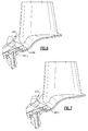
- the inner vane platform 44 and the blade platform section 66 disclosed herein provide non-axisymmetric surface features to a leading portion 44L, 66L, a trailing portion 44T, 66L and various combinations thereof to counteract the non-uniform (circumferentially) static-pressure distortions engendered by hot combustion products H to reduce purge-flow requirements and also reduce aerodynamic losses.
- the trailing portion 44T is contoured in a radial direction on an undersurface 44T-L.
- the undersurface 44T-L may, in one non-limiting embodiment, be contoured to provide a non-axisymmetric surface such as a waveform surface ( Figure 6 ).
- An upper surface 44Tu of the trailing portion 44T may define a conventional axisymmetric surface.
- the undersurface 44L-L of the leading portion 44L may also be so contoured in a radial direction.
- the trailing portion 44T may also be contoured in an axial direction on a trailing edge 44TE.
- the trailing edge 44TE may, in one non-limiting embodiment, be contoured to provide a non-axisymmetric surface such as a waveform surface ( Figure 7 ).
- a leading edge 44LE may also be so contoured in an axial direction ( Figure 7 ).
- non-axisymmetric radial surface contour undersurface 44T-L of the trailing portion 44T may be combined in various manners in relation to the hot combustion products H to reduce purge-flow requirements and also reduce aerodynamic losses.
- the non-axisymmetric radial surface contour undersurface 44T-L of the trailing portion 44T may all be utilized together.
- the non-axisymmetric radial surface contour undersurface 44L-L of the leading portion 44L may all be utilized together.
- the leading portion 66L of the blade platform section 66 may be contoured in a radial direction.
- the leading edge 66LE may, alternatively or additionally, be contoured to provide an axial non-axisymmetric surface such as a waveform surface ( Figure 9 ).
- the entire platform leading edge 66LE forms the wave-like shape.
- a lower surface 66L-L and or the upper surface 66Lu of the leading portion 66L may define either a conventional axisymmetric surface or be contoured to provide a non-axisymmetric surface such as a waveform surface ( Figure 10 ).
- the undersurface 66T-L of the trailing portion 66T may also be so contoured in a radial direction ( Figure 11 ).
- the leading portion 66L may also be contoured in an axial direction on a leading edge 66LE.
- the leading edge 66LE may, in one non-limiting embodiment, be contoured to provide a non-axisymmetric surface such as a waveform surface.
- the trailing edge portion 66TE may be contoured in an axial direction to provide a non-axisymmetric surface such as a waveform surface.
- non-axisymmetric radial surface contour undersurface 66T-L of the trailing portion 66T may be combined in various manners in relation to the hot combustion products to reduce purge-flow requirements and also reduce aerodynamic losses
- features of the non-axisymmetric radial and/or axial surface contour of the blade platform section 66 and features of the non-axisymmetric radial and/or axial surface contour of the inner vane platform 44 may be combined in various manners to further reduce purge-flow requirements and aerodynamic losses.
Landscapes
- Engineering & Computer Science (AREA)
- Mechanical Engineering (AREA)
- General Engineering & Computer Science (AREA)
- Physics & Mathematics (AREA)
- Fluid Mechanics (AREA)
- Turbine Rotor Nozzle Sealing (AREA)
Applications Claiming Priority (1)
| Application Number | Priority Date | Filing Date | Title |
|---|---|---|---|
| US12/753,211 US9976433B2 (en) | 2010-04-02 | 2010-04-02 | Gas turbine engine with non-axisymmetric surface contoured rotor blade platform |
Publications (2)
| Publication Number | Publication Date |
|---|---|
| EP2372102A2 true EP2372102A2 (fr) | 2011-10-05 |
| EP2372102A3 EP2372102A3 (fr) | 2014-11-05 |
Family
ID=43858254
Family Applications (1)
| Application Number | Title | Priority Date | Filing Date |
|---|---|---|---|
| EP11161072.1A Withdrawn EP2372102A3 (fr) | 2010-04-02 | 2011-04-04 | Plate-forme des pales de rotor d'une turbine à gaz |
Country Status (2)
| Country | Link |
|---|---|
| US (1) | US9976433B2 (fr) |
| EP (1) | EP2372102A3 (fr) |
Cited By (6)
| Publication number | Priority date | Publication date | Assignee | Title |
|---|---|---|---|---|
| WO2013009449A1 (fr) * | 2011-07-12 | 2013-01-17 | Siemens Energy, Inc. | Élément de direction d'écoulement pour moteur de turbine à gaz |
| EP2607625A1 (fr) | 2011-12-20 | 2013-06-26 | MTU Aero Engines GmbH | Turbomachine et étage de turbomachine |
| EP2607626A1 (fr) | 2011-12-20 | 2013-06-26 | MTU Aero Engines GmbH | Turbomachine et étage de turbomachine |
| EP3156592A1 (fr) * | 2015-10-15 | 2017-04-19 | United Technologies Corporation | Ensemble d'étanchéité pour cavité de turbine |
| EP3369892A1 (fr) * | 2017-03-03 | 2018-09-05 | MTU Aero Engines GmbH | Contournage d'une plate-forme de grille d'aube |
| FR3107301A1 (fr) * | 2020-02-19 | 2021-08-20 | Safran Aircraft Engines | aube pour roue aubagée mobile de turbomachine d’aéronef comprenant un becquet d’étanchéité à section évolutive optimisée |
Families Citing this family (18)
| Publication number | Priority date | Publication date | Assignee | Title |
|---|---|---|---|---|
| US8979481B2 (en) * | 2011-10-26 | 2015-03-17 | General Electric Company | Turbine bucket angel wing features for forward cavity flow control and related method |
| DE102012206126B4 (de) * | 2012-04-13 | 2014-06-05 | MTU Aero Engines AG | Laufschaufel sowie Strömungsmaschine |
| US9091173B2 (en) | 2012-05-31 | 2015-07-28 | United Technologies Corporation | Turbine coolant supply system |
| US9267386B2 (en) | 2012-06-29 | 2016-02-23 | United Technologies Corporation | Fairing assembly |
| US10344601B2 (en) | 2012-08-17 | 2019-07-09 | United Technologies Corporation | Contoured flowpath surface |
| US9297263B2 (en) * | 2012-10-31 | 2016-03-29 | Solar Turbines Incorporated | Turbine blade for a gas turbine engine |
| EP2986823B1 (fr) | 2013-04-18 | 2017-11-08 | United Technologies Corporation | Composant avec profil d'aube |
| US20160208626A1 (en) * | 2015-01-19 | 2016-07-21 | United Technologies Corporation | Integrally bladed rotor with pressure side thickness on blade trailing edge |
| US10240462B2 (en) | 2016-01-29 | 2019-03-26 | General Electric Company | End wall contour for an axial flow turbine stage |
| FR3052804B1 (fr) * | 2016-06-16 | 2018-05-25 | Safran Aircraft Engines | Roue aubagee volontairement desaccordee |
| US10577955B2 (en) | 2017-06-29 | 2020-03-03 | General Electric Company | Airfoil assembly with a scalloped flow surface |
| KR102000281B1 (ko) * | 2017-10-11 | 2019-07-15 | 두산중공업 주식회사 | 압축기 및 이를 포함하는 가스 터빈 |
| JP7246959B2 (ja) * | 2019-02-14 | 2023-03-28 | 三菱重工コンプレッサ株式会社 | タービン翼及び蒸気タービン |
| US20210079799A1 (en) * | 2019-09-12 | 2021-03-18 | General Electric Company | Nozzle assembly for turbine engine |
| FR3106627B1 (fr) * | 2020-01-24 | 2023-03-17 | Safran Aircraft Engines | Basculement en vagues aux entrefers rotor-stator dans un compresseur de turbomachine |
| USD946527S1 (en) * | 2020-09-04 | 2022-03-22 | Siemens Energy Global GmbH & Co. KG | Turbine blade |
| USD949794S1 (en) * | 2020-09-04 | 2022-04-26 | Siemens Energy Global GmbH & Co. KG | Turbine blade |
| USD949793S1 (en) * | 2020-09-04 | 2022-04-26 | Siemens Energy Global GmbH & Co. KG | Turbine blade |
Family Cites Families (68)
| Publication number | Priority date | Publication date | Assignee | Title |
|---|---|---|---|---|
| US2918254A (en) | 1954-05-10 | 1959-12-22 | Hausammann Werner | Turborunner |
| US3014695A (en) * | 1960-02-03 | 1961-12-26 | Gen Electric | Turbine bucket retaining means |
| US3756740A (en) * | 1971-08-11 | 1973-09-04 | M Deich | Turbine stage |
| US4218178A (en) | 1978-03-31 | 1980-08-19 | General Motors Corporation | Turbine vane structure |
| US4271005A (en) | 1979-12-03 | 1981-06-02 | United Technologies Corporation | Workpiece support apparatus for use with cathode sputtering devices |
| DE3023466C2 (de) | 1980-06-24 | 1982-11-25 | MTU Motoren- und Turbinen-Union München GmbH, 8000 München | Einrichtung zur Verminderung von Sekundärströmungsverlusten in einem beschaufelten Strömungskanal |
| US4677828A (en) | 1983-06-16 | 1987-07-07 | United Technologies Corporation | Circumferentially area ruled duct |
| US4714410A (en) * | 1986-08-18 | 1987-12-22 | Westinghouse Electric Corp. | Trailing edge support for control stage steam turbine blade |
| FR2643940B1 (fr) | 1989-03-01 | 1991-05-17 | Snecma | Aube mobile de turbomachine a moment de pied compense |
| US5397215A (en) | 1993-06-14 | 1995-03-14 | United Technologies Corporation | Flow directing assembly for the compression section of a rotary machine |
| GB2281356B (en) | 1993-08-20 | 1997-01-29 | Rolls Royce Plc | Gas turbine engine turbine |
| GB2294732A (en) | 1994-11-05 | 1996-05-08 | Rolls Royce Plc | Integral disc seal for turbomachine |
| US5836744A (en) * | 1997-04-24 | 1998-11-17 | United Technologies Corporation | Frangible fan blade |
| DE29715180U1 (de) | 1997-08-23 | 1997-10-16 | Mtu Muenchen Gmbh | Leitschaufel für eine Gasturbine |
| JP4502517B2 (ja) | 1999-03-24 | 2010-07-14 | シーメンス アクチエンゲゼルシヤフト | 流体機械の案内羽根及び案内羽根リング |
| US6276432B1 (en) | 1999-06-10 | 2001-08-21 | Howmet Research Corporation | Directional solidification method and apparatus |
| GB9915648D0 (en) | 1999-07-06 | 1999-09-01 | Rolls Royce Plc | Improvement in or relating to turbine blades |
| US6511294B1 (en) * | 1999-09-23 | 2003-01-28 | General Electric Company | Reduced-stress compressor blisk flowpath |
| JP2001152804A (ja) * | 1999-11-19 | 2001-06-05 | Mitsubishi Heavy Ind Ltd | ガスタービン設備及びタービン翼 |
| US6343912B1 (en) | 1999-12-07 | 2002-02-05 | General Electric Company | Gas turbine or jet engine stator vane frame |
| GB0003676D0 (en) | 2000-02-17 | 2000-04-05 | Abb Alstom Power Nv | Aerofoils |
| JP2001271602A (ja) | 2000-03-27 | 2001-10-05 | Honda Motor Co Ltd | ガスタービンエンジン |
| US6524070B1 (en) | 2000-08-21 | 2003-02-25 | General Electric Company | Method and apparatus for reducing rotor assembly circumferential rim stress |
| DE10051223A1 (de) | 2000-10-16 | 2002-04-25 | Alstom Switzerland Ltd | Verbindbare Statorelemente |
| US6471474B1 (en) | 2000-10-20 | 2002-10-29 | General Electric Company | Method and apparatus for reducing rotor assembly circumferential rim stress |
| DE10064265A1 (de) | 2000-12-22 | 2002-07-04 | Alstom Switzerland Ltd | Vorrichtung und Verfahren zur Kühlung einer Plattform einer Turbinenschaufel |
| US6430917B1 (en) | 2001-02-09 | 2002-08-13 | The Regents Of The University Of California | Single rotor turbine engine |
| US6431820B1 (en) | 2001-02-28 | 2002-08-13 | General Electric Company | Methods and apparatus for cooling gas turbine engine blade tips |
| US6514041B1 (en) | 2001-09-12 | 2003-02-04 | Alstom (Switzerland) Ltd | Carrier for guide vane and heat shield segment |
| WO2003052240A2 (fr) * | 2001-12-14 | 2003-06-26 | Alstom Technology Ltd | Systeme de turbine a gaz |
| US6672832B2 (en) | 2002-01-07 | 2004-01-06 | General Electric Company | Step-down turbine platform |
| EP1331361B1 (fr) | 2002-01-17 | 2010-05-12 | Siemens Aktiengesellschaft | Aube statorique de turbine coulée ayant un crochet de fixation |
| DE50202538D1 (de) | 2002-01-17 | 2005-04-28 | Siemens Ag | Turbinenschaufel mit einer Heissgasplattform und einer Lastplattform |
| US6821087B2 (en) * | 2002-01-21 | 2004-11-23 | Honda Giken Kogyo Kabushiki Kaisha | Flow-rectifying member and its unit and method for producing flow-rectifying member |
| US6669445B2 (en) | 2002-03-07 | 2003-12-30 | United Technologies Corporation | Endwall shape for use in turbomachinery |
| EP1413715A1 (fr) | 2002-10-21 | 2004-04-28 | Siemens Aktiengesellschaft | Dispositif de refroidissement pour une plate-forme d'une aube d'une turbine à gaz |
| US6761536B1 (en) | 2003-01-31 | 2004-07-13 | Power Systems Mfg, Llc | Turbine blade platform trailing edge undercut |
| US6991428B2 (en) | 2003-06-12 | 2006-01-31 | Pratt & Whitney Canada Corp. | Fan blade platform feature for improved blade-off performance |
| US7044718B1 (en) | 2003-07-08 | 2006-05-16 | The Regents Of The University Of California | Radial-radial single rotor turbine |
| EP1515000B1 (fr) | 2003-09-09 | 2016-03-09 | Alstom Technology Ltd | Aubage d'une turbomachine avec un carenage contouré |
| US7600972B2 (en) * | 2003-10-31 | 2009-10-13 | General Electric Company | Methods and apparatus for cooling gas turbine engine rotor assemblies |
| US6932577B2 (en) * | 2003-11-21 | 2005-08-23 | Power Systems Mfg., Llc | Turbine blade airfoil having improved creep capability |
| EP1557534A1 (fr) | 2004-01-20 | 2005-07-27 | Siemens Aktiengesellschaft | Aube de turbine à gaz et turbine à gaz avec une telle aube |
| JP2005233141A (ja) | 2004-02-23 | 2005-09-02 | Mitsubishi Heavy Ind Ltd | 動翼およびその動翼を用いたガスタービン |
| US7452184B2 (en) | 2004-12-13 | 2008-11-18 | Pratt & Whitney Canada Corp. | Airfoil platform impingement cooling |
| US7134842B2 (en) | 2004-12-24 | 2006-11-14 | General Electric Company | Scalloped surface turbine stage |
| US7244104B2 (en) * | 2005-05-31 | 2007-07-17 | Pratt & Whitney Canada Corp. | Deflectors for controlling entry of fluid leakage into the working fluid flowpath of a gas turbine engine |
| EP1731711A1 (fr) | 2005-06-10 | 2006-12-13 | Siemens Aktiengesellschaft | Transition de la chambre de combustion à la turbine, écran thermique et aube du distributeur de turbine |
| US7300253B2 (en) | 2005-07-25 | 2007-11-27 | Siemens Aktiengesellschaft | Gas turbine blade or vane and platform element for a gas turbine blade or vane ring of a gas turbine, supporting structure for securing gas turbine blades or vanes arranged in a ring, gas turbine blade or vane ring and the use of a gas turbine blade or vane ring |
| US7467922B2 (en) | 2005-07-25 | 2008-12-23 | Siemens Aktiengesellschaft | Cooled turbine blade or vane for a gas turbine, and use of a turbine blade or vane of this type |
| US20070031260A1 (en) * | 2005-08-03 | 2007-02-08 | Dube Bryan P | Turbine airfoil platform platypus for low buttress stress |
| US7467924B2 (en) | 2005-08-16 | 2008-12-23 | United Technologies Corporation | Turbine blade including revised platform |
| US7384243B2 (en) | 2005-08-30 | 2008-06-10 | General Electric Company | Stator vane profile optimization |
| US7628578B2 (en) | 2005-09-12 | 2009-12-08 | Pratt & Whitney Canada Corp. | Vane assembly with improved vane roots |
| US7484936B2 (en) | 2005-09-26 | 2009-02-03 | Pratt & Whitney Canada Corp. | Blades for a gas turbine engine with integrated sealing plate and method |
| US7540709B1 (en) | 2005-10-20 | 2009-06-02 | Florida Turbine Technologies, Inc. | Box rim cavity for a gas turbine engine |
| US7465155B2 (en) | 2006-02-27 | 2008-12-16 | Honeywell International Inc. | Non-axisymmetric end wall contouring for a turbomachine blade row |
| GB2437298B (en) * | 2006-04-18 | 2008-10-01 | Rolls Royce Plc | A Seal Between Rotor Blade Platforms And Stator Vane Platforms, A Rotor Blade And A Stator Vane |
| US7625172B2 (en) | 2006-04-26 | 2009-12-01 | United Technologies Corporation | Vane platform cooling |
| US7862300B2 (en) * | 2006-05-18 | 2011-01-04 | Wood Group Heavy Industrial Turbines Ag | Turbomachinery blade having a platform relief hole |
| US7597536B1 (en) | 2006-06-14 | 2009-10-06 | Florida Turbine Technologies, Inc. | Turbine airfoil with de-coupled platform |
| US7581930B2 (en) | 2006-08-16 | 2009-09-01 | United Technologies Corporation | High lift transonic turbine blade |
| US7497663B2 (en) | 2006-10-26 | 2009-03-03 | General Electric Company | Rotor blade profile optimization |
| FR2928174B1 (fr) | 2008-02-28 | 2011-05-06 | Snecma | Aube avec plateforme non axisymetrique : creux et bosse sur extrados. |
| US8162598B2 (en) * | 2008-09-25 | 2012-04-24 | Siemens Energy, Inc. | Gas turbine sealing apparatus |
| US8206115B2 (en) | 2008-09-26 | 2012-06-26 | General Electric Company | Scalloped surface turbine stage with trailing edge ridges |
| US9039375B2 (en) * | 2009-09-01 | 2015-05-26 | General Electric Company | Non-axisymmetric airfoil platform shaping |
| US8356975B2 (en) | 2010-03-23 | 2013-01-22 | United Technologies Corporation | Gas turbine engine with non-axisymmetric surface contoured vane platform |
-
2010
- 2010-04-02 US US12/753,211 patent/US9976433B2/en active Active
-
2011
- 2011-04-04 EP EP11161072.1A patent/EP2372102A3/fr not_active Withdrawn
Non-Patent Citations (1)
| Title |
|---|
| None |
Cited By (13)
| Publication number | Priority date | Publication date | Assignee | Title |
|---|---|---|---|---|
| WO2013009449A1 (fr) * | 2011-07-12 | 2013-01-17 | Siemens Energy, Inc. | Élément de direction d'écoulement pour moteur de turbine à gaz |
| US8864452B2 (en) | 2011-07-12 | 2014-10-21 | Siemens Energy, Inc. | Flow directing member for gas turbine engine |
| EP2607625A1 (fr) | 2011-12-20 | 2013-06-26 | MTU Aero Engines GmbH | Turbomachine et étage de turbomachine |
| EP2607626A1 (fr) | 2011-12-20 | 2013-06-26 | MTU Aero Engines GmbH | Turbomachine et étage de turbomachine |
| US9863251B2 (en) | 2011-12-20 | 2018-01-09 | Mtu Aero Engines Gmbh | Turbomachine and turbomachine stage |
| EP3156592A1 (fr) * | 2015-10-15 | 2017-04-19 | United Technologies Corporation | Ensemble d'étanchéité pour cavité de turbine |
| EP3369892A1 (fr) * | 2017-03-03 | 2018-09-05 | MTU Aero Engines GmbH | Contournage d'une plate-forme de grille d'aube |
| US10648339B2 (en) | 2017-03-03 | 2020-05-12 | MTU Aero Engines AG | Contouring a blade/vane cascade stage |
| FR3107301A1 (fr) * | 2020-02-19 | 2021-08-20 | Safran Aircraft Engines | aube pour roue aubagée mobile de turbomachine d’aéronef comprenant un becquet d’étanchéité à section évolutive optimisée |
| WO2021165600A1 (fr) * | 2020-02-19 | 2021-08-26 | Safran Aircraft Engines | Aube pour roue aubagee mobile de turbomachine d'aeronef comprenant un becquet d'etancheite a section evolutive optimisee |
| CN115151710A (zh) * | 2020-02-19 | 2022-10-04 | 赛峰飞机发动机公司 | 用于飞行器涡轮发动机的旋转叶片盘的包括具有优化的非恒定横截面的密封唇的叶片 |
| US11867065B2 (en) | 2020-02-19 | 2024-01-09 | Safran Aircraft Engines | Blade for a rotating bladed disk for an aircraft turbine engine comprising a sealing lip having an optimized non-constant cross section |
| CN115151710B (zh) * | 2020-02-19 | 2024-05-07 | 赛峰飞机发动机公司 | 用于飞行器涡轮发动机的旋转叶片盘的包括具有优化的非恒定横截面的密封唇的叶片 |
Also Published As
| Publication number | Publication date |
|---|---|
| US20110243749A1 (en) | 2011-10-06 |
| US9976433B2 (en) | 2018-05-22 |
| EP2372102A3 (fr) | 2014-11-05 |
Similar Documents
| Publication | Publication Date | Title |
|---|---|---|
| EP2937515B1 (fr) | Moteur à turbine à gaz doté d'une plateforme de pale de rotor contourée à surface non axisymétrique | |
| US9976433B2 (en) | Gas turbine engine with non-axisymmetric surface contoured rotor blade platform | |
| US11041392B2 (en) | Attachment faces for clamped turbine stator of a gas turbine engine | |
| EP2961943B1 (fr) | Procédé et appareil de gestion d'écoulement de pré-diffuseur pour un compartiment de palier | |
| EP3594452B1 (fr) | Joint segmenté pour un moteur à turbine à gaz | |
| EP2998520B1 (fr) | Joint inter-étages pour moteur à turbine à gaz | |
| US11021990B2 (en) | Shroud sealing for a gas turbine engine | |
| US20090067978A1 (en) | Variable area turbine vane arrangement | |
| WO2015021029A1 (fr) | Joint étanche à l'air extérieur pour aube pourvu d'une caractéristique de charge radiale | |
| EP3023594B1 (fr) | Ensemble de stator avec interface de tampon pour une turbine à gaz | |
| EP3617458B1 (fr) | Joint annulaire pour un moteur à turbine à gaz | |
| EP3225785A2 (fr) | Joint de cannelure pour moteur de turbine à gaz | |
| EP2995778A1 (fr) | Procédé et ensemble permettant de réduire la chaleur secondaire dans un moteur à turbine à gaz | |
| US10590777B2 (en) | Turbomachine rotor blade | |
| US20220213802A1 (en) | System for controlling blade clearances within a gas turbine engine | |
| EP3000966B1 (fr) | Procédé et ensemble permettant de réduire la chaleur secondaire dans un moteur à turbine à gaz | |
| US11959390B2 (en) | Gas turbine engine exhaust case with blade shroud and stiffeners | |
| US10619492B2 (en) | Vane air inlet with fillet |
Legal Events
| Date | Code | Title | Description |
|---|---|---|---|
| PUAI | Public reference made under article 153(3) epc to a published international application that has entered the european phase |
Free format text: ORIGINAL CODE: 0009012 |
|
| AK | Designated contracting states |
Kind code of ref document: A2 Designated state(s): AL AT BE BG CH CY CZ DE DK EE ES FI FR GB GR HR HU IE IS IT LI LT LU LV MC MK MT NL NO PL PT RO RS SE SI SK SM TR |
|
| AX | Request for extension of the european patent |
Extension state: BA ME |
|
| PUAL | Search report despatched |
Free format text: ORIGINAL CODE: 0009013 |
|
| AK | Designated contracting states |
Kind code of ref document: A3 Designated state(s): AL AT BE BG CH CY CZ DE DK EE ES FI FR GB GR HR HU IE IS IT LI LT LU LV MC MK MT NL NO PL PT RO RS SE SI SK SM TR |
|
| AX | Request for extension of the european patent |
Extension state: BA ME |
|
| RIC1 | Information provided on ipc code assigned before grant |
Ipc: F01D 5/22 20060101ALI20140930BHEP Ipc: F01D 5/14 20060101ALI20140930BHEP Ipc: F01D 11/00 20060101AFI20140930BHEP |
|
| STAA | Information on the status of an ep patent application or granted ep patent |
Free format text: STATUS: THE APPLICATION IS DEEMED TO BE WITHDRAWN |
|
| 18D | Application deemed to be withdrawn |
Effective date: 20150507 |