EP2371541B1 - System and method for digital creation of a print master using a multiple printhead unit - Google Patents
System and method for digital creation of a print master using a multiple printhead unit Download PDFInfo
- Publication number
- EP2371541B1 EP2371541B1 EP10158421.7A EP10158421A EP2371541B1 EP 2371541 B1 EP2371541 B1 EP 2371541B1 EP 10158421 A EP10158421 A EP 10158421A EP 2371541 B1 EP2371541 B1 EP 2371541B1
- Authority
- EP
- European Patent Office
- Prior art keywords
- marking
- distance
- elements
- longitudinal axis
- cylindrical support
- Prior art date
- Legal status (The legal status is an assumption and is not a legal conclusion. Google has not performed a legal analysis and makes no representation as to the accuracy of the status listed.)
- Not-in-force
Links
- 238000000034 method Methods 0.000 title claims description 21
- 239000013598 vector Substances 0.000 claims description 13
- 239000007788 liquid Substances 0.000 claims description 4
- 238000007639 printing Methods 0.000 description 14
- 239000012530 fluid Substances 0.000 description 13
- 230000000694 effects Effects 0.000 description 6
- 238000003384 imaging method Methods 0.000 description 4
- 230000003993 interaction Effects 0.000 description 4
- 238000000151 deposition Methods 0.000 description 2
- 238000009826 distribution Methods 0.000 description 2
- 230000005855 radiation Effects 0.000 description 2
- 239000000758 substrate Substances 0.000 description 2
- 241001479434 Agfa Species 0.000 description 1
- 238000002679 ablation Methods 0.000 description 1
- 238000007774 anilox coating Methods 0.000 description 1
- 238000010420 art technique Methods 0.000 description 1
- 239000011096 corrugated fiberboard Substances 0.000 description 1
- 230000008878 coupling Effects 0.000 description 1
- 238000010168 coupling process Methods 0.000 description 1
- 238000005859 coupling reaction Methods 0.000 description 1
- 238000001035 drying Methods 0.000 description 1
- 238000007647 flexography Methods 0.000 description 1
- -1 for example Substances 0.000 description 1
- 238000007641 inkjet printing Methods 0.000 description 1
- 239000004973 liquid crystal related substance Substances 0.000 description 1
- 238000004519 manufacturing process Methods 0.000 description 1
- 239000000463 material Substances 0.000 description 1
- 239000002184 metal Substances 0.000 description 1
- 230000000737 periodic effect Effects 0.000 description 1
- 239000002985 plastic film Substances 0.000 description 1
- 229920006255 plastic film Polymers 0.000 description 1
- 239000002243 precursor Substances 0.000 description 1
Images


Classifications
-
- B—PERFORMING OPERATIONS; TRANSPORTING
- B41—PRINTING; LINING MACHINES; TYPEWRITERS; STAMPS
- B41C—PROCESSES FOR THE MANUFACTURE OR REPRODUCTION OF PRINTING SURFACES
- B41C1/00—Forme preparation
- B41C1/003—Forme preparation the relief or intaglio pattern being obtained by imagewise deposition of a liquid, e.g. by an ink jet
-
- B—PERFORMING OPERATIONS; TRANSPORTING
- B05—SPRAYING OR ATOMISING IN GENERAL; APPLYING FLUENT MATERIALS TO SURFACES, IN GENERAL
- B05D—PROCESSES FOR APPLYING FLUENT MATERIALS TO SURFACES, IN GENERAL
- B05D5/00—Processes for applying liquids or other fluent materials to surfaces to obtain special surface effects, finishes or structures
- B05D5/02—Processes for applying liquids or other fluent materials to surfaces to obtain special surface effects, finishes or structures to obtain a matt or rough surface
-
- B—PERFORMING OPERATIONS; TRANSPORTING
- B29—WORKING OF PLASTICS; WORKING OF SUBSTANCES IN A PLASTIC STATE IN GENERAL
- B29C—SHAPING OR JOINING OF PLASTICS; SHAPING OF MATERIAL IN A PLASTIC STATE, NOT OTHERWISE PROVIDED FOR; AFTER-TREATMENT OF THE SHAPED PRODUCTS, e.g. REPAIRING
- B29C59/00—Surface shaping of articles, e.g. embossing; Apparatus therefor
- B29C59/16—Surface shaping of articles, e.g. embossing; Apparatus therefor by wave energy or particle radiation, e.g. infrared heating
-
- B—PERFORMING OPERATIONS; TRANSPORTING
- B41—PRINTING; LINING MACHINES; TYPEWRITERS; STAMPS
- B41C—PROCESSES FOR THE MANUFACTURE OR REPRODUCTION OF PRINTING SURFACES
- B41C1/00—Forme preparation
- B41C1/18—Curved printing formes or printing cylinders
-
- B—PERFORMING OPERATIONS; TRANSPORTING
- B41—PRINTING; LINING MACHINES; TYPEWRITERS; STAMPS
- B41J—TYPEWRITERS; SELECTIVE PRINTING MECHANISMS, i.e. MECHANISMS PRINTING OTHERWISE THAN FROM A FORME; CORRECTION OF TYPOGRAPHICAL ERRORS
- B41J19/00—Character- or line-spacing mechanisms
- B41J19/16—Special spacing mechanisms for circular, spiral, or diagonal-printing apparatus
-
- B—PERFORMING OPERATIONS; TRANSPORTING
- B41—PRINTING; LINING MACHINES; TYPEWRITERS; STAMPS
- B41C—PROCESSES FOR THE MANUFACTURE OR REPRODUCTION OF PRINTING SURFACES
- B41C1/00—Forme preparation
- B41C1/02—Engraving; Heads therefor
- B41C1/04—Engraving; Heads therefor using heads controlled by an electric information signal
- B41C1/05—Heat-generating engraving heads, e.g. laser beam, electron beam
Definitions
- the invention deals with the field of creating print masters, and more specifically with digital methods and systems for creating a flexographic print master on a drum by means of a fluid depositing printhead.
- the invention reduces a problem that may result when a printhead unit is used that uses more than one nozzle row.
- a flexible cylindrical relief print master is used for transferring a fast drying ink from an anilox roller to a printable substrate.
- the print master can be a flexible plate that is mounted on a cylinder, or it can be a cylindrical sleeve.
- the raised portions of the relief print master define the image features that are to be printed.
- the process is particularly suitable for printing on a wide range of printable substrates including for example, corrugated fiberboard, plastic films, or even metal sheets.
- a traditional method for creating a print master uses a light sensitive polymerisable sheet that is exposed by a UV radiation source through a negative film or a negative mask layer (“LAMS"-system) that defines the image features. Under the influence of the UV radiation, the sheet will polymerize underneath the transparent portions of the film. The remaining portions are removed, and what remains is a positive relief print plate.
- LAMS negative mask layer
- a relief print master can be digitally represented by a stack of two-dimensional layers and discloses a method for calculating these two-dimensional layers.
- the application EP-A 2199066 teaches a method for spatially diffusing nozzle related artifacts in the three dimensions of the stack of two-dimensional layers.
- Both applications also teach a composition of a fluid that can be used for printing a relief print master, and a method and apparatus for printing such a relief print master.
- US2004/252174 discloses a printing apparatus adapted for printing on a printing surface of a three-dimensional object.
- the apparatus comprises an inkjet printhead having a plurality of nozzles, and being operative to effect relative movement of the printhead and the object, during printing, with a rotational component about an axis of rotation and with a linear component, in which the linear component is at least partially in a direction substantially parallel with the axis of rotation and wherein the nozzle pitch of the printhead is greater than the grid pitch to be printed onto the printing surface in the nozzle row direction.
- a substantially helical path is printed on the surface.
- US2005/046651 discloses an apparatus and method for ink-jet printing onto an intermediate drum in a helical pattern while correcting for image skew and aliasing.
- a plurality of ink-jet print heads place an image on an intermediate drum, impervious to ink, in a helical patter.
- the image is altered by nozzle placement and image manipulation to correct for skewing errors, and thereafter, the nozzle timing is adjusted to correct for aliasing.
- the plurality of print heads move parallel to the axis of rotation of the drum while the drum is simultaneously rotating, causing the image to be placed in a helical pattern.
- FIG. 1 shows an embodiment of such an apparatus 100.
- 140 is a rotating drum that is driven by a motor 110.
- a printhead 150 moves in a slow scan direction Y parallel with the axis of the drum at a linear velocity that is coupled to the rotational speed X of the drum.
- the printhead jets droplets of a polymerisable fluid onto a removable sleeve 130 that is mounted on the drum 140. These droplets are gradually cured by a curing source 160 that moves along with the printhead and provides local curing.
- the curing source 170 provides an optional and final curing step that determines the final physical characteristics of the relief print master 120.
- the printhead 300 has nozzles 310 that are arranged on a single axis 320 and that have a periodic nozzle pitch 330.
- FIG. 2 demonstrates that, as the printhead moves from left to right in the direction Y, droplets 250 are jetted onto the sleeve 240, whereby the "leading" part 211 of the printhead 210 prints droplets that belong to a lower layer 220, whereas the "trailing" part 212 of the printhead 210 prints droplets of an upper layer 230.
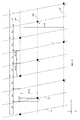
- each nozzle of the printhead jets fluid along a spiral path on the rotating drum. This is illustrated in FIG. 5 , where it is shown that fluid droplets ejected by nozzle 1 describe a spiral path 520 that has a pitch 510.
- the pitch 510 of the spiral path 520 was selected to be exactly double the length of the nozzle pitch 530 of the printhead 540.
- the effect of this is that all the droplets of nozzles 1, 3, 5 having an odd index number fall on the first spiral path 520, whereas the droplets ejected by nozzles 2, 4, 6 having an even index number fall on the second spiral path 550.
- Both spiral paths 520 550 are interlaced and spaced at an even distance 560 that corresponds with the nozzle pitch 530.
- the lowest value of the nozzle pitch 330 in FIG. 3 is constrained by technical limitations in the production of a printhead.
- One solution to overcome this constraint is to use a multiple printhead unit.
- FIG. 4 The concept of a multiple printhead unit is explained by means of FIG. 4 .
- two printheads 401 and 402 are mounted back to back to form a multiple printhead unit 400.
- the effective nozzle pitch 431 of the back to back head is half the nozzle pitch of each printhead 401, 402 and the effective printing resolution is doubled.
- FIG. 6 shows a first spiral path 610 on which fluid droplets from the nozzles having an odd index number 1, 3 and 5 land and a second spiral path 611 on which the fluid droplets of the nozzles having an even index number 2, 4 and 6 land.
- the nozzles with an odd index number are located on a first axis 620 and the nozzles having an even index number are located on a second axis 621, parallel with the first axis 620.
- the spiral paths 610 and 611 are not evenly spaced with regard to each other.
- the distance 640 is different from the distance 641.
- the uneven spacing of the spiral paths 610 and 611 causes an uneven distribution of the fluid droplets along the Y direction when they are jetted onto the sleeve and this negatively affects the quality of the print master that is printed.
- the object of the current invention is to improve the evenness of the distribution of fluid droplets that are jetted onto a drum to create a relief print master using a back to back printhead unit or - more in general - a printhead unit that comprises multiple printheads.
- the distance between the interlaced spiral paths can be adjusted so that they become evenly spaced.
- 600 is a rotating sleeve or support that has a diameter 601 represented by the variable SleeveDiameter.
- the circumference of the sleeve is represented by the variable SleeveCircumforence and has a value equal to.
- SleeveCircumference PI * SleeveDiameter
- the sleeve rotates in a X direction at a frequency that is represented by the variable NumberofRevolutionsperSecond.
- CircumferentialSpeed SleeveCircumference * NumberofRevolutionsperSecond
- the direction and magnitude of the circumferential speed defines a first speed vector 670 that is tangential to the cylindrical sleeve and perpendicular to its axis.
- the distance between two neighboring nozzles in a single printhead is the nozzle pitch 631 and is represented by a variable P.
- the multiple printhead unit as shown in FIG. 6 two printheads are positioned in such a way that the nozzles in the printheads are interlaced.
- the nozzles on a second row 621 of nozzles in a second printhead are shifted over a distance P/2 (630 in FIG. 6 ) with regard to the nozzles on a first row 620 of nozzles in a first printhead.
- the resulting two printhead unit has a nozzle pitch 630 that is half the nozzle pitch 631 of the constituting printheads. This means that the resulting multiple printhead unit has an intrinsic resolution that is double of the resolution of the constituting printheads.
- the movement of the printhead is locked to the rotation of the sleeve by means of a mechanical coupling (for example by means of a worm and gear) or by means of an electronic gear (electronically coupled servomotors).
- a mechanical coupling for example by means of a worm and gear
- an electronic gear electrostatically coupled servomotors.
- PrintheadPitch IntegerMultiplier * P / 2
- PrintheadSpeed PrintheadPitch / RevolutionPeriod
- the speed and magnitude of the printhead defines a second speed vector 671.
- the sum of the two speed vectors 670 and 671 corresponds with the speed vector 672.
- This speed vector is tangential to the spiral path on which liquid droplets are jetted.
- the distance 660 between two nozzle rows 620 and 621 in FIG. 6 is represented by the variable D .
- the two spiral paths 610, 611 in FIG. 6 are not evenly spaced along the Y direction. More specifically, the distance 640 in FIG. 6 is shorter than the distance 641. This is a result of the distance 660 between the two nozzle rows 620, 621.
- FIG. 7 shows a detail of FIG. 6 that is used for geometrically describing the difference between the distance 640 and the distance 641 in FIG. 6 .
- the length of the distance D is negligible with regard to the length of the Circumference .
- the cylindrical surface of the sleeve can be approximated by a plane so that conventional (two-dimensional) trigonometry can be used to describe the geometrical relationships between the different variables.
- the distance dY corresponds with the amount that the distance A is shorter than the distance P/2 (half the nozzle pitch), and the amount that the distance E is longer than the distance P/2 .
- FIG. 9 gives a further illustration of the invention.
- the invention is not limited to a combined head that uses only two rows of nozzles.
- the number of rows of nozzles can, in principle, be any integer number N (such as 2, 3, 4 or more).
- FIG. 10 An example of a system that uses three rows of nozzles is shown in FIG. 10 .
- a first printhead has a first row of nozzles 1021
- a second printhead has a second row of nozzles 1022
- a third printhead has a third row of nozzles 1023.
- a more general embodiment of a printhead unit has N nozzle rows having index numbers 1, 2, 3, 4 ... N .
- the index numbers of the nozzle rows do not necessarily correspond with the order that the nozzle rows are physically mounted.
- the distance in the X dimension between the first nozzle row 1021 and the second nozzle row 1022 has a value D[1][2]
- the distance in the X dimension between the first nozzle row 1021 and the third nozzle row 1023 is D[1][3].
- the distance between a first nozzle row having an index number i and a second nozzle row having an index number j is equal to D[i][j] and can be obtained by subtracting the value of an X coordinate of the first nozzle row with index number i from the value of an X coordinate of the second nozzle row having index number j.
- Each individual printhead in FIG. 10 has a pitch P .
- the second row of nozzles 1022 is shifted over a distance P/3 in the Y dimension with regard to the first nozzle row 1021 and the third nozzle row 1023 is shifted over a distance 2*P/3 in the Y dimension with regard to the first nozzle row 1021.
- the second nozzle row 1022 is shifted over a distance 2*P/3 and the third nozzle row 1023 over a distance P/3 in the Y dimension with regard to the first nozzle row 1021.
- a row of nozzles is shifted in the Y dimension over an additional distance that corresponds with an arbitrary multiple of the pitch P .
- the second row of nozzles 1022 could be shifted additionally over a distance of 2*P so that the total shift becomes 2*P+2*P/3
- the third row of nozzles over an additional distance of 5*P so that the total shift becomes 5P+1*P/3 .
- a printhead unit comprises N printheads
- the nozzle rows are shifted in the Y dimension with regard to a first nozzle row over distances m*P/N that are integer multiples of P/N so that the pitch of the resulting printhead unit becomes equal to P/N .
- FIG. 11 demonstrates the effect of the distance D[1][2] on the distance A[1][2] in the Y dimension between a first spiral path 1111 on which droplets are ejected by nozzle belonging to nozzle row 1021 and a second spiral path 1112 on which droplets are ejected by a second nozzle row 1022.
- This distance A[1][2] is equal to:
- a 1 ⁇ 2 P / 3 - D 1 ⁇ 2 * tan ⁇
- FIG. 11 demonstrates the effect of the distance D[1][3] on the distance A[1][3] in the Y dimension between a first spiral path 1111 on which droplets are ejected by nozzles belonging to nozzle row 1021 and a third spiral path 1113 on which droplets are ejected by nozzles belonging to a third nozzle row 1023.
- FIG. 12 shows how the current invention can be advantageously used for equalizing the distances between three different spiral paths.
- the nozzle row 1023 is shifted over a distance 2*P/3 + D[1][3]*tan ( ⁇ ) in the Y dimension with regard to the nozzle row 1021.
- the distance between the spiral paths 1111 and 1113 is now equal 2*P/3 .
- the effect of the invention is that the distances between two neighboring spiral paths are always equal to P/3 .
- the spiral paths are equally spaced with regard to each other in the Y dimension.
- a first example of an alternative recording system is a laser imaging system that uses a laserhead with rows of laser elements as marking elements.
- a second example of an alternative recording system uses a spatial light modulator with rows of light valves as marking elements.
- spatial light modulators are liquid crystal devices or grating light valves.
- a third example of an alternative recording system uses rows of digital mirror devices.
- a laser based marking system can be used to expose an offset print master precursor.
- a light valve marking system can be used to expose an offset print master precursor.
- a digital mirror device marking system can be used to expose an offset print master precursor.
- the invention is advantageously used for creating a relief print master.
- a relief print master can also be obtained for example by using one of the following embodiments.
- an imaging system is used for selectively exposing a mask layer that is on top of a flexible, photopolymerizable layer.
- the exposed areas of the mask layer harden out, constitute a mask and after UV flood exposure and processing define the features of the print master that are in relief.
- the unexposed areas are removed during processing and define the recessed portions of the relief print master.
- the imaging system selectively exposes a flexible, elastomeric layer, whereby material is directly removed from the flexible layer upon impingement, and the recessed portions of the relief print master are formed.
- the unexposed areas of the flexible layer define the relief features of the print master.
- an imaging system is used for selectively exposing a mask layer that is on top of a flexible, photopolymerizable layer.
- the exposed areas of the mask layer are partially removed as a result of ablation.
- a mask is constituted and after UV flood exposure and processing the exposed areas are removed and define the recessed portions of the print master.
- the unexposed areas define the features of the print master that are in relief.
Description
- The invention deals with the field of creating print masters, and more specifically with digital methods and systems for creating a flexographic print master on a drum by means of a fluid depositing printhead.
- The invention reduces a problem that may result when a printhead unit is used that uses more than one nozzle row.
- In flexographic printing or flexography a flexible cylindrical relief print master is used for transferring a fast drying ink from an anilox roller to a printable substrate. The print master can be a flexible plate that is mounted on a cylinder, or it can be a cylindrical sleeve.
- The raised portions of the relief print master define the image features that are to be printed.
- Because the flexographic print master has elastic properties, the process is particularly suitable for printing on a wide range of printable substrates including for example, corrugated fiberboard, plastic films, or even metal sheets.
- A traditional method for creating a print master uses a light sensitive polymerisable sheet that is exposed by a UV radiation source through a negative film or a negative mask layer ("LAMS"-system) that defines the image features. Under the influence of the UV radiation, the sheet will polymerize underneath the transparent portions of the film. The remaining portions are removed, and what remains is a positive relief print plate.
- In the unpublished applications
EP-A 2199066 andEP-A 2199065 , both assigned to Agfa Graphics NV and having a priority date of 2008-12-19, a digital solution is presented for creating a relief print master using a fluid droplet depositing printhead. - The application
EP-A 2199065 teaches that a relief print master can be digitally represented by a stack of two-dimensional layers and discloses a method for calculating these two-dimensional layers. - The application
EP-A 2199066 teaches a method for spatially diffusing nozzle related artifacts in the three dimensions of the stack of two-dimensional layers. - Both applications also teach a composition of a fluid that can be used for printing a relief print master, and a method and apparatus for printing such a relief print master.
-
US2004/252174 discloses a printing apparatus adapted for printing on a printing surface of a three-dimensional object. The apparatus comprises an inkjet printhead having a plurality of nozzles, and being operative to effect relative movement of the printhead and the object, during printing, with a rotational component about an axis of rotation and with a linear component, in which the linear component is at least partially in a direction substantially parallel with the axis of rotation and wherein the nozzle pitch of the printhead is greater than the grid pitch to be printed onto the printing surface in the nozzle row direction. In preferred examples, a substantially helical path is printed on the surface. -
US2005/046651 discloses an apparatus and method for ink-jet printing onto an intermediate drum in a helical pattern while correcting for image skew and aliasing. A plurality of ink-jet print heads place an image on an intermediate drum, impervious to ink, in a helical patter. To compensate for helical printing, the image is altered by nozzle placement and image manipulation to correct for skewing errors, and thereafter, the nozzle timing is adjusted to correct for aliasing. The plurality of print heads move parallel to the axis of rotation of the drum while the drum is simultaneously rotating, causing the image to be placed in a helical pattern. -
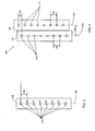
FIG. 1 shows an embodiment of such anapparatus 100. 140 is a rotating drum that is driven by amotor 110. Aprinthead 150 moves in a slow scan direction Y parallel with the axis of the drum at a linear velocity that is coupled to the rotational speed X of the drum. The printhead jets droplets of a polymerisable fluid onto aremovable sleeve 130 that is mounted on thedrum 140. These droplets are gradually cured by acuring source 160 that moves along with the printhead and provides local curing. When therelief print master 130 has been printed, thecuring source 170 provides an optional and final curing step that determines the final physical characteristics of therelief print master 120. - An example of a printhead is shown in
FIG. 3 . Theprinthead 300 hasnozzles 310 that are arranged on asingle axis 320 and that have aperiodic nozzle pitch 330. -
FIG. 2 demonstrates that, as the printhead moves from left to right in the direction Y,droplets 250 are jetted onto thesleeve 240, whereby the "leading"part 211 of theprinthead 210 prints droplets that belong to alower layer 220, whereas the "trailing"part 212 of theprinthead 210 prints droplets of anupper layer 230. - Because in the apparatus in
FIG. 1 and 2 the linear velocity of the printhead in the direction Y is directly coupled with the rotational speed X of thecylindrical sleeve FIG. 5 , where it is shown that fluid droplets ejected bynozzle 1 describe aspiral path 520 that has apitch 510. - In
FIG. 5 , thepitch 510 of thespiral path 520 was selected to be exactly double the length of thenozzle pitch 530 of theprinthead 540. The effect of this is that all the droplets ofnozzles spiral path 520, whereas the droplets ejected bynozzles spiral path 550. Bothspiral paths 520 550 are interlaced and spaced at aneven distance 560 that corresponds with thenozzle pitch 530. - The lowest value of the
nozzle pitch 330 inFIG. 3 is constrained by technical limitations in the production of a printhead. One solution to overcome this constraint is to use a multiple printhead unit. - The concept of a multiple printhead unit is explained by means of
FIG. 4 . As the figure shows, twoprintheads multiple printhead unit 400. By staggering the position of thenozzles 410 on theaxis 420 ofhead 401 and thenozzles 411 onaxis 421 ofprinthead 402 over a distance of half a nozzle pitch, theeffective nozzle pitch 431 of the back to back head is half the nozzle pitch of eachprinthead - The use of a multiple printhead unit in an apparatus as shown in
FIG. 1 or FIG. 2 for the purpose of printing a relief print master introduces an unexpected and undesirable side effect. -
FIG. 6 . shows a first spiral path 610 on which fluid droplets from the nozzles having anodd index number index number - The nozzles with an odd index number are located on a
first axis 620 and the nozzles having an even index number are located on asecond axis 621, parallel with thefirst axis 620. - Because these two
axes FIG. 6 thedistance 640 is different from thedistance 641. - The uneven spacing of the spiral paths 610 and 611 causes an uneven distribution of the fluid droplets along the Y direction when they are jetted onto the sleeve and this negatively affects the quality of the print master that is printed.
- The object of the current invention is to improve the evenness of the distribution of fluid droplets that are jetted onto a drum to create a relief print master using a back to back printhead unit or - more in general - a printhead unit that comprises multiple printheads.
- The invention is realized by means of a system and a method as described in the claims.
- By slightly shifting the nozzle rows in a multiple printhead unit with regard to each other, the distance between the interlaced spiral paths can be adjusted so that they become evenly spaced.
-
-
FIG. 1 shows an embodiment of an apparatus for printing a relief print master on a sleeve; -
FIG. 2 shows a different view of an embodiment of an apparatus for printing a relief print master on a sleeve. -
FIG. 3 shows a printhead with a single row of nozzles; -
FIG. 4 shows a multiple printhead unit with two rows of nozzles; -
FIG. 5 shows two spiral paths on which the fluid droplets ejected by the nozzles of a printhead as inFIG. 3 land. -
FIG. 6 shows two spiral paths on which the fluid droplets land that are ejected by the nozzles of a printhead as inFIG. 4 . -
FIG. 7 describes in detail the geometrical interactions between the movements of the printhead and the cylindrical sleeve, and the distance between the spiral paths when the axis of the printhead is parallel with the axis of the cylindrical sleeve. -
FIG. 8 describes in detail the geometrical interactions between the movements of the printhead and the cylindrical sleeve, and the distance between the spiral paths when the nozzle rows of the printhead are shifted with regard to each other. -
FIG. 9 shows an embodiment according to the current invention in which the nozzle rows are shifted with regard to each other. -
FIG. 10 shows a printhead unit that comprises not two but three printheads. -
FIG. 11 describes in detail the geometrical interactions between the movements of the printhead and the cylindrical sleeve, and the distance between the spiral paths when the axis of the printhead is parallel with the axis of the cylindrical sleeve for the case that a printhead unit is used that comprises three printheads. -
FIG. 12 describes in detail the geometrical interactions between the movements of the printhead and the cylindrical sleeve, and the distance between the spiral paths when the nozzle rows of the printhead are shifted with regard to each other for the case that a printhead unit is used that comprises three printheads. - Referring to
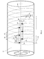
FIG. 6 , 600 is a rotating sleeve or support that has adiameter 601 represented by the variable SleeveDiameter. - The circumference of the sleeve is represented by the variable SleeveCircumforence and has a value equal to.

- The sleeve rotates in a X direction at a frequency that is represented by the variable NumberofRevolutionsperSecond. The time of one revolution is represented by the variable RevolutionPeriod. It is equal to:

- The circumferential speed of the sleeve has a value CircumferentialSpeed. It is equal to:

- The direction and magnitude of the circumferential speed defines a
first speed vector 670 that is tangential to the cylindrical sleeve and perpendicular to its axis. - The distance between two neighboring nozzles in a single printhead is the
nozzle pitch 631 and is represented by a variable P. - In the multiple printhead unit as shown in
FIG. 6 , two printheads are positioned in such a way that the nozzles in the printheads are interlaced. In a prior art technique, the nozzles on asecond row 621 of nozzles in a second printhead are shifted over a distance P/2 (630 inFIG. 6 ) with regard to the nozzles on afirst row 620 of nozzles in a first printhead. The resulting two printhead unit has anozzle pitch 630 that is half thenozzle pitch 631 of the constituting printheads. This means that the resulting multiple printhead unit has an intrinsic resolution that is double of the resolution of the constituting printheads. - The movement of the printhead is locked to the rotation of the sleeve by means of a mechanical coupling (for example by means of a worm and gear) or by means of an electronic gear (electronically coupled servomotors). During a single revolution of the sleeve, the printhead moves over a
distance 650 that is represented by a variable PrintheadPitch. The value of this distance should be an integer multiple, represented by a variable IntegerMultiplier of the distance between two neighboring nozzles:
- The speed at which the printhead moves in the Y direction is represented by the variable PrintheadSpeed. Its value is equal to:

- The speed and magnitude of the printhead defines a
second speed vector 671. - The sum of the two
speed vectors speed vector 672. This speed vector is tangential to the spiral path on which liquid droplets are jetted. The angle α between thespeed vector 672 and thefirst speed vector 670 is expressed by:

- The
distance 660 between twonozzle rows FIG. 6 is represented by the variable D. - Unlike in
FIG. 5 , the two spiral paths 610, 611 inFIG. 6 are not evenly spaced along the Y direction. More specifically, thedistance 640 inFIG. 6 is shorter than thedistance 641. This is a result of thedistance 660 between the twonozzle rows -
FIG. 7 shows a detail ofFIG. 6 that is used for geometrically describing the difference between thedistance 640 and thedistance 641 inFIG. 6 . - It is assumed that the length of the distance D is negligible with regard to the length of the Circumference. In that case the cylindrical surface of the sleeve can be approximated by a plane so that conventional (two-dimensional) trigonometry can be used to describe the geometrical relationships between the different variables.
- In
FIG 7 : - the distance P corresponds with the
nozzle pitch 631 inFIG. 6 ; - the distance D corresponds with the
distance 660 between two nozzle rows inFIG. 6 ; - the distance A corresponds with the
distance 640 between two spiral paths inFIG. 6 ; - the distance E corresponds with the
distance 641 between two spiral paths inFIG. 6 . - The distance dY corresponds with the amount that the distance A is shorter than the distance P/2 (half the nozzle pitch), and the amount that the distance E is longer than the distance P/2. This is mathematically expressed as follows:


- The value of dY can be directly expressed as a function of the angle α and the nozzle row distance D:


- And hence:

- The above expression teaches that:

when at least one of the following two conditions is met: - 1. D = 0 (this is the situation that is shown in
FIG. 5 ) - 2. α = 0 (this situation is only approximated when the PrintheadPitch is very small with respect to the CircumferentialSpeed, which is the case in many practical situations)
- The above expression also teaches that dY becomes larger when the distance D between the nozzle rows increases or when the ratio (tan(α)) of the PrintheadSpeed over the CircumferentialSpeed increases.
- We will now describe by means of
FIG. 8 that it is possible to reduce dY, or even to make equal to zero and hence to make:
without setting α = 0 or setting D = 0, but instead by shifting one of the nozzle rows in the multiple printhead unit with regard to the other nozzle row over a specific distance S. - In
FIG. 8 , the value of A is expressed as:

- If the following value for S is selected:

then it is obtained that:
- In other words, by shifting one of the rows of nozzles over a distance S that is equal to D * tan(α), it is obtained that these interlaced paths are equidistant at a distance equal to P/2.
-
FIG. 9 gives a further illustration of the invention. By shifting the two rows of nozzles with regard to each other, it is possible to equalize thedistance 910 between thespiral paths - The above description provides an exemplary embodiment of the current invention on which a number of variations exist.
- In the first place it is not always required that the shifting S of a nozzle row is exactly equal to D * tan(α). It was already demonstrated by means of
FIG. 7 that if the distance D between the nozzle rows is small compared to the circumference of the cylindrical sleeve, that the deviation dY is small compared to the distance P of the nozzle pitch. In that case a shift S of the row of nozzles by an amount that is less than D * tan(α) provides already a sufficient improvement of the evenness of the distances A and E between the spiral paths. In general, a shift of r * D * tan(α) in which r is a parameter that has a value of approximately one will already improve the evenness of the distances A and E - Preferably:

in which:
- Even more preferably:

- Even more preferably:

- And most preferably:

- In the second place, the invention is not limited to a combined head that uses only two rows of nozzles. The number of rows of nozzles can, in principle, be any integer number N (such as 2, 3, 4 or more).
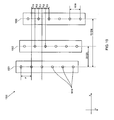
- An example of a system that uses three rows of nozzles is shown in
FIG. 10 . A first printhead has a first row ofnozzles 1021, a second printhead has a second row ofnozzles 1022 and a third printhead has a third row ofnozzles 1023. - A more general embodiment of a printhead unit has N nozzle rows having
index numbers - The distance in the X dimension between the
first nozzle row 1021 and thesecond nozzle row 1022 has a value D[1][2], whereas the distance in the X dimension between thefirst nozzle row 1021 and thethird nozzle row 1023 is D[1][3]. - In a more general embodiment the distance between a first nozzle row having an index number i and a second nozzle row having an index number j is equal to D[i][j] and can be obtained by subtracting the value of an X coordinate of the first nozzle row with index number i from the value of an X coordinate of the second nozzle row having index number j.
- Each individual printhead in
FIG. 10 has a pitch P. In a prior art system, the second row ofnozzles 1022 is shifted over a distance P/3 in the Y dimension with regard to thefirst nozzle row 1021 and thethird nozzle row 1023 is shifted over adistance 2*P/3 in the Y dimension with regard to thefirst nozzle row 1021. - In a perfectly equivalent embodiment the
second nozzle row 1022 is shifted over adistance 2*P/3 and thethird nozzle row 1023 over a distance P/3 in the Y dimension with regard to thefirst nozzle row 1021. - In yet another equivalent embodiment, a row of nozzles is shifted in the Y dimension over an additional distance that corresponds with an arbitrary multiple of the pitch P. For example: the second row of
nozzles 1022 could be shifted additionally over a distance of 2*P so that the total shift becomes 2*P+2*P/3, and the third row of nozzles over an additional distance of 5*P so that the total shift becomes 5P+1*P/3. - Of the essence is that shifting the
nozzle rows - In the case that a printhead unit comprises N printheads, the nozzle rows are shifted in the Y dimension with regard to a first nozzle row over distances m*P/N that are integer multiples of P/N so that the pitch of the resulting printhead unit becomes equal to P/N.
-
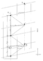
FIG. 11 demonstrates the effect of the distance D[1][2] on the distance A[1][2] in the Y dimension between afirst spiral path 1111 on which droplets are ejected by nozzle belonging tonozzle row 1021 and asecond spiral path 1112 on which droplets are ejected by asecond nozzle row 1022. This distance A[1][2] is equal to:


- Similarly
FIG. 11 demonstrates the effect of the distance D[1][3] on the distance A[1][3] in the Y dimension between afirst spiral path 1111 on which droplets are ejected by nozzles belonging tonozzle row 1021 and athird spiral path 1113 on which droplets are ejected by nozzles belonging to athird nozzle row 1023. This distance A[1][3] is equal to:


- In a general prior art embodiment with N printheads, a distance A[i][j] between a first spiral path on which droplets are ejected by nozzles belonging to a first nozzle row having an index number i and a second spiral path on which droplets are ejected by nozzles belonging to a nozzle row having an index number j, whereby D[i][j] refers to the distance in the X direction between the nozzle rows having index numbers i and j meets the equation:

in which m is an integer. -
FIG. 12 shows how the current invention can be advantageously used for equalizing the distances between three different spiral paths. - In
FIG. 12 thenozzle row 1022 is shifted over a distance P/3 + D[1][2]*tan(α) in the Y dimension with regard to thenozzle row 1021. As a result, the distance between thespiral paths - Similarly, the
nozzle row 1023 is shifted over adistance 2*P/3 + D[1][3]*tan(α) in the Y dimension with regard to thenozzle row 1021. As a result, the distance between thespiral paths - The effect of the invention is that the distances between two neighboring spiral paths are always equal to P/3. In other words, the spiral paths are equally spaced with regard to each other in the Y dimension.
- In the general case of a printhead unit that includes N printheads, according to the invention, a second nozzle row having an index number j is shifted with regard to a first nozzle row having an index number i in the Y dimension over a distance S that meets the following equation:

whereby D[i][j] refers to the distance between the first nozzle row having an index number i and the a second nozzle row having an index number j, and whereby m refers to an integer number. - Whereas the invention has been described in the context of an apparatus for creating a flexographic print master using a printhead that comprises fluid ejecting nozzles, it can just as well be used for other external drum based recording systems that use parallel rows of marking elements.
- A first example of an alternative recording system is a laser imaging system that uses a laserhead with rows of laser elements as marking elements.
- A second example of an alternative recording system uses a spatial light modulator with rows of light valves as marking elements. Examples of spatial light modulators are liquid crystal devices or grating light valves.
- A third example of an alternative recording system uses rows of digital mirror devices.
- All these systems can be used for creating a print master. For example, a laser based marking system, a light valve marking system or a digital mirror device marking system can be used to expose an offset print master precursor.
- Using the embodiment shown in
FIG. 1 and 2 that was earlier explained, the invention is advantageously used for creating a relief print master. - A relief print master can also be obtained for example by using one of the following embodiments.
- In a first embodiment an imaging system according to the current invention is used for selectively exposing a mask layer that is on top of a flexible, photopolymerizable layer. The exposed areas of the mask layer harden out, constitute a mask and after UV flood exposure and processing define the features of the print master that are in relief. The unexposed areas are removed during processing and define the recessed portions of the relief print master.
- In a second embodiment, the imaging system according to the current invention selectively exposes a flexible, elastomeric layer, whereby material is directly removed from the flexible layer upon impingement, and the recessed portions of the relief print master are formed. In this case the unexposed areas of the flexible layer define the relief features of the print master.
- In a third embodiment an imaging system according to the current invention is used for selectively exposing a mask layer that is on top of a flexible, photopolymerizable layer. The exposed areas of the mask layer are partially removed as a result of ablation. As a result a mask is constituted and after UV flood exposure and processing the exposed areas are removed and define the recessed portions of the print master. The unexposed areas define the features of the print master that are in relief.
Claims (20)
- A system (100) for preparing a print master (120) by means of a marking engine, the system comprising:- a cylindrical support (600) having a longitudinal axis (680);- a marking head for marking at least one layer of marks on the cylindrical support,■ whereby the cylindrical support rotates around its longitudinal axis relative to the marking head at a first speed, said rotation defining a first speed vector (670) that is tangential to the cylindrical support,■ whereby the marking head moves along a slow scan direction parallel to the longitudinal axis at a second speed that is locked to the first speed, said moving defining a second speed vector (671),■ whereby the sum (672) of the first (670) and the second (671) speed vectors defines an angle α with regard to a tangential line that is orthogonal to the axis (680) of the cylindrical support,■ whereby the marking head comprises N (N>1) parallel rows of marking elements (620, 621) that can create marks along interlaced spiral paths (610, 611) around the longitudinal axis,■ each row of marking elements (620, 621) having a marking pitch P (631),■ the marking elements in the different rows being interlaced for increasing the resolution of the marking head by a factor of N,■ the distance in a direction orthogonal to the longitudinal axis between a first row of marking elements having an index number i and a second row of marking elements having an index number j having a non zero value of D[i][j] (660), this distance D[i][j] (660) introducing uneven spacing (640, 641) between the spiral paths (610, 611),the system characterized in that:- the distance (920) measured in the direction of the longitudinal axis (680) of the cylindrical support between nozzles in the first and second rows (620, 621) is equal to m*P/N + r*D[i][i]*tan(α), wherein m is an integer number and wherein 0.1 < r < 1.9, so that the unevenness of the spacing (910) between the spiral paths (950, 951) is reduced or eliminated.
- A system according to claim 1, wherein the marking head is an inkjet printhead and the marking elements are inkjet nozzles.
- A system according to claim 2, whereby the inkjet printhead ejects droplets of a curable liquid and whereby the system further comprises a curing source (160, 170).
- A system according to anyone of the claims 1 to 3, wherein the print master is a flexographic print master.
- A system according to claim 1, wherein the marking head is a laserhead and the marking elements are laser elements.
- A system according to claim 1, wherein the marking head is a spatial light modulator, and wherein the marking elements are light valves.
- A system according to claim 1, wherein the marking head is a digital mirror device, and wherein the marking elements are mirrors.
- A system according to anyone of the claims 1 to 7 wherein 0.5 < r < 1.5.
- A system according to claim 8 wherein 0.9 < r < 1.1.
- A system according to claim 9 wherein 0.99 < r < 1.01.
- A method for preparing a print master (120) by means of a marking engine that comprises a marking head,
the method comprising the steps of:- marking with a marking head at least one layer of marks on a cylindrical support (600), the cylindrical support having a longitudinal axis (680),- rotating the cylindrical support around the longitudinal axis relative to the marking head at a first speed, said rotation defining a first speed vector (670) that is tangential to the cylindrical support (600);- moving the marking head at a second speed in a slow scan direction that is parallel to the longitudinal axis (680) and that is locked to the first speed, said moving defining a second speed vector (671);- whereby the sum (672) of the first (670) and second speed (671) vectors defines an angle α with regard to a tangential line that is orthogonal to the axis (680) of the cylindrical support;- whereby the marking head comprises N (N>1) parallel rows (620, 621) of marking elements that can create marks along interlaced spiral paths (610, 611) around the longitudinal axis (680);- each row of marking elements having a marking pitch P (631), the marking elements in the different rows (620, 621) being interlaced for increasing the resolution of the marking head by a factor of N,- the distance in a direction orthogonal to the longitudinal axis between a first row of marking elements having an index number i and a second row of marking elements having a index number j having a non zero value D[i][j] (660), this distance D[i][j] (660) introducing uneven spacing (640, 641) between the spiral paths (610, 611),the method characterized in that it comprises an additional step of:- shifting the marking elements in two adjacent rows (620, 621) of marking elements in the direction of the longitudinal axis of the cylindrical support over a distance (920) that is equal to p*P/N + r*D[i][j]*tan(α), wherein 0.1 < r < 1.9 and wherein j is an integer number, so that the unevenness of the spacing (910) between the spiral paths (950, 951) is reduced or eliminated. - A method according to claim 11, wherein the marking head is an inkjet printhead and wherein the marking elements are inkjet nozzles.
- A method according to claim 12, whereby the inkjet printhead ejects droplets of a curable liquid and further comprising a step of curing the curable liquid by means of a curing source (160, 170).
- A method according to anyone of the claims 11 to 13 wherein the print master is a flexographic print master.
- A method according to claim 11, wherein the marking head is a laserhead and the marking elements are laser elements.
- A method according to claim 11, wherein the marking head is a spatial light modulator and the marking elements are light valves.
- A method according to claim 11, wherein the marking head is a digital mirror device and
wherein the marking elements are mirrors. - A method according to anyone of the claims 11 to 17 wherein 0.5 < r < 1.5.
- A method according to claim 18 wherein 0.9 < r < 1.1.
- A method according to claim 19 wherein 0.99 < r < 1.01.
Priority Applications (7)
| Application Number | Priority Date | Filing Date | Title |
|---|---|---|---|
| EP10158421.7A EP2371541B1 (en) | 2010-03-30 | 2010-03-30 | System and method for digital creation of a print master using a multiple printhead unit |
| CN201180017417.3A CN102811861B (en) | 2010-03-30 | 2011-03-21 | System and method for digital creation of a print master using a multiple printhead unit |
| JP2013501744A JP5832513B2 (en) | 2010-03-30 | 2011-03-21 | Digital creation system and method of print master using multiple print head units |
| PCT/EP2011/054177 WO2011120831A1 (en) | 2010-03-30 | 2011-03-21 | System and method for digital creation of a print master using a multiple printhead unit |
| BR112012024452A BR112012024452A2 (en) | 2010-03-30 | 2011-03-21 | system and method for digitally creating a print matrix using a multiple printhead unit |
| US13/581,691 US9199272B2 (en) | 2010-03-30 | 2011-03-21 | System and method for digital creation of a print master using a multiple printhead unit |
| IN8184CHN2012 IN2012CN08184A (en) | 2010-03-30 | 2012-09-24 |
Applications Claiming Priority (1)
| Application Number | Priority Date | Filing Date | Title |
|---|---|---|---|
| EP10158421.7A EP2371541B1 (en) | 2010-03-30 | 2010-03-30 | System and method for digital creation of a print master using a multiple printhead unit |
Publications (2)
| Publication Number | Publication Date |
|---|---|
| EP2371541A1 EP2371541A1 (en) | 2011-10-05 |
| EP2371541B1 true EP2371541B1 (en) | 2013-06-05 |
Family
ID=42358362
Family Applications (1)
| Application Number | Title | Priority Date | Filing Date |
|---|---|---|---|
| EP10158421.7A Not-in-force EP2371541B1 (en) | 2010-03-30 | 2010-03-30 | System and method for digital creation of a print master using a multiple printhead unit |
Country Status (7)
| Country | Link |
|---|---|
| US (1) | US9199272B2 (en) |
| EP (1) | EP2371541B1 (en) |
| JP (1) | JP5832513B2 (en) |
| CN (1) | CN102811861B (en) |
| BR (1) | BR112012024452A2 (en) |
| IN (1) | IN2012CN08184A (en) |
| WO (1) | WO2011120831A1 (en) |
Cited By (1)
| Publication number | Priority date | Publication date | Assignee | Title |
|---|---|---|---|---|
| CN107000424A (en) * | 2014-10-16 | 2017-08-01 | 温德默勒&霍乐沙两合公司 | The method for producing printing picture structure |
Families Citing this family (6)
| Publication number | Priority date | Publication date | Assignee | Title |
|---|---|---|---|---|
| US9309341B2 (en) | 2010-12-20 | 2016-04-12 | Agfa Graphics Nv | Curable jettable fluid for making a flexographic printing master |
| CN105283807B (en) | 2013-06-18 | 2019-09-27 | 爱克发有限公司 | Prepare the method with the Lighographic printing plate precursor of patterning backing layer |
| WO2016043750A1 (en) * | 2014-09-18 | 2016-03-24 | Halliburton Energy Services, Inc. | Electrically conductive pattern printer for downhole tools |
| CN108127300A (en) * | 2017-12-30 | 2018-06-08 | 浙江凡左科技有限公司 | Angularly equidistant unified regulator |
| WO2020003084A1 (en) * | 2018-06-29 | 2020-01-02 | 3M Innovative Properties Company | Nonplanar patterned nanostructured surface and printing methods for making thereof |
| EP4263732A1 (en) | 2020-12-21 | 2023-10-25 | Agfa-Gevaert Nv | Nir absorbing inkjet ink, method of recording |
Family Cites Families (24)
| Publication number | Priority date | Publication date | Assignee | Title |
|---|---|---|---|---|
| US4992890A (en) * | 1989-03-17 | 1991-02-12 | Intergraph Corporation | System for plotting and scanning graphic images |
| JPH04223175A (en) * | 1990-12-25 | 1992-08-13 | Rohm Co Ltd | Ink jet print head |
| JPH07156380A (en) * | 1993-12-08 | 1995-06-20 | Seiko Epson Corp | Ink jet recorder |
| US6270335B2 (en) | 1995-09-27 | 2001-08-07 | 3D Systems, Inc. | Selective deposition modeling method and apparatus for forming three-dimensional objects and supports |
| DE19627098A1 (en) | 1996-07-05 | 1998-01-08 | Asea Brown Boveri | Circuit breaker |
| JP3395123B2 (en) * | 1997-07-15 | 2003-04-07 | 株式会社ミヤコシ | Inkjet printer |
| JP2000025207A (en) * | 1998-07-07 | 2000-01-25 | Toppan Printing Co Ltd | Ink jet recorder and recording method |
| JP2001109163A (en) * | 1999-08-03 | 2001-04-20 | Think Laboratory Co Ltd | Plate-making exposure device and method thereof |
| GB2376920A (en) * | 2001-06-27 | 2002-12-31 | Inca Digital Printers Ltd | Inkjet printing on a three-dimensional object including relative movement of a printhead and the object during printing about a rotational axis |
| US6814425B2 (en) * | 2002-04-12 | 2004-11-09 | Hewlett-Packard Development Company, L.P. | Droplet placement onto surfaces |
| US7875321B2 (en) * | 2002-12-11 | 2011-01-25 | Agfa Graphics Nv | Preparation of flexographic printing plates using ink jet recording |
| EP1428666B1 (en) | 2002-12-11 | 2007-04-25 | Agfa Graphics N.V. | Preparation of flexographic printing plates using ink jet recording |
| JP4415564B2 (en) * | 2003-05-09 | 2010-02-17 | コニカミノルタエムジー株式会社 | Inkjet recording device |
| ATE392940T1 (en) * | 2003-08-13 | 2008-05-15 | Shell Int Research | GAS-LIQUID CONTACT GROUND |
| US7052125B2 (en) * | 2003-08-28 | 2006-05-30 | Lexmark International, Inc. | Apparatus and method for ink-jet printing onto an intermediate drum in a helical pattern |
| CN100497929C (en) * | 2005-04-21 | 2009-06-10 | 无锡油泵油嘴研究所 | Oil thrower of Co-rail system |
| JP2007098617A (en) * | 2005-09-30 | 2007-04-19 | Mitsubishi Heavy Ind Ltd | Printing plate manufacturing apparatus and printing machine |
| US20090197013A1 (en) | 2008-02-04 | 2009-08-06 | Ffei Limited | Producing a flexographic printing plate |
| US8563892B2 (en) | 2008-09-24 | 2013-10-22 | Standex International Corporation | Method and apparatus for laser engraving |
| ATE550170T1 (en) | 2008-12-19 | 2012-04-15 | Agfa Graphics Nv | IMAGE PROCESSING METHOD FOR THREE-DIMENSIONAL PRINTING |
| EP2199066B1 (en) | 2008-12-19 | 2013-11-06 | Agfa Graphics N.V. | Method for reducing image quality artifacts in three-dimensional printing |
| EP2420382B1 (en) | 2010-08-20 | 2013-10-16 | Agfa Graphics N.V. | System and method for digital creation of a print master using a multiple printhead unit |
| EP2420383B1 (en) | 2010-08-20 | 2013-10-16 | Agfa Graphics N.V. | Digital system for creating a flexographic printmaster |
| EP2465678B1 (en) | 2010-12-16 | 2013-08-07 | Agfa Graphics N.V. | System and method for the digital creation of a print master by means of a liquid droplet deposition apparatus. |
-
2010
- 2010-03-30 EP EP10158421.7A patent/EP2371541B1/en not_active Not-in-force
-
2011
- 2011-03-21 CN CN201180017417.3A patent/CN102811861B/en not_active Expired - Fee Related
- 2011-03-21 US US13/581,691 patent/US9199272B2/en not_active Expired - Fee Related
- 2011-03-21 WO PCT/EP2011/054177 patent/WO2011120831A1/en active Application Filing
- 2011-03-21 JP JP2013501744A patent/JP5832513B2/en not_active Expired - Fee Related
- 2011-03-21 BR BR112012024452A patent/BR112012024452A2/en not_active IP Right Cessation
-
2012
- 2012-09-24 IN IN8184CHN2012 patent/IN2012CN08184A/en unknown
Cited By (1)
| Publication number | Priority date | Publication date | Assignee | Title |
|---|---|---|---|---|
| CN107000424A (en) * | 2014-10-16 | 2017-08-01 | 温德默勒&霍乐沙两合公司 | The method for producing printing picture structure |
Also Published As
| Publication number | Publication date |
|---|---|
| JP5832513B2 (en) | 2015-12-16 |
| CN102811861A (en) | 2012-12-05 |
| IN2012CN08184A (en) | 2015-09-11 |
| CN102811861B (en) | 2014-09-17 |
| EP2371541A1 (en) | 2011-10-05 |
| BR112012024452A2 (en) | 2016-05-31 |
| US9199272B2 (en) | 2015-12-01 |
| US20120321795A1 (en) | 2012-12-20 |
| JP2013527810A (en) | 2013-07-04 |
| WO2011120831A1 (en) | 2011-10-06 |
Similar Documents
| Publication | Publication Date | Title |
|---|---|---|
| EP2420382B1 (en) | System and method for digital creation of a print master using a multiple printhead unit | |
| EP2371541B1 (en) | System and method for digital creation of a print master using a multiple printhead unit | |
| EP2465678B1 (en) | System and method for the digital creation of a print master by means of a liquid droplet deposition apparatus. | |
| KR101705419B1 (en) | Methods of manufacture and use of customized flexomaster patterns for flexographic printing | |
| EP2420383B1 (en) | Digital system for creating a flexographic printmaster | |
| JP2011011532A (en) | Gravure printing plate | |
| CN101456309A (en) | Letterpress printing plate |
Legal Events
| Date | Code | Title | Description |
|---|---|---|---|
| PUAI | Public reference made under article 153(3) epc to a published international application that has entered the european phase |
Free format text: ORIGINAL CODE: 0009012 |
|
| AK | Designated contracting states |
Kind code of ref document: A1 Designated state(s): AT BE BG CH CY CZ DE DK EE ES FI FR GB GR HR HU IE IS IT LI LT LU LV MC MK MT NL NO PL PT RO SE SI SK SM TR |
|
| 17P | Request for examination filed |
Effective date: 20120405 |
|
| REG | Reference to a national code |
Ref country code: DE Ref legal event code: R079 Ref document number: 602010007484 Country of ref document: DE Free format text: PREVIOUS MAIN CLASS: B41C0001000000 Ipc: B41J0019160000 |
|
| RIC1 | Information provided on ipc code assigned before grant |
Ipc: B41C 1/00 20060101ALI20120703BHEP Ipc: B41J 19/16 20060101AFI20120703BHEP Ipc: B41C 1/18 20060101ALI20120703BHEP |
|
| GRAP | Despatch of communication of intention to grant a patent |
Free format text: ORIGINAL CODE: EPIDOSNIGR1 |
|
| GRAS | Grant fee paid |
Free format text: ORIGINAL CODE: EPIDOSNIGR3 |
|
| GRAA | (expected) grant |
Free format text: ORIGINAL CODE: 0009210 |
|
| STAA | Information on the status of an ep patent application or granted ep patent |
Free format text: STATUS: THE PATENT HAS BEEN GRANTED |
|
| AK | Designated contracting states |
Kind code of ref document: B1 Designated state(s): AT BE BG CH CY CZ DE DK EE ES FI FR GB GR HR HU IE IS IT LI LT LU LV MC MK MT NL NO PL PT RO SE SI SK SM TR |
|
| REG | Reference to a national code |
Ref country code: GB Ref legal event code: FG4D |
|
| REG | Reference to a national code |
Ref country code: CH Ref legal event code: EP |
|
| REG | Reference to a national code |
Ref country code: AT Ref legal event code: REF Ref document number: 615416 Country of ref document: AT Kind code of ref document: T Effective date: 20130615 |
|
| REG | Reference to a national code |
Ref country code: IE Ref legal event code: FG4D |
|
| REG | Reference to a national code |
Ref country code: NL Ref legal event code: T3 |
|
| REG | Reference to a national code |
Ref country code: DE Ref legal event code: R096 Ref document number: 602010007484 Country of ref document: DE Effective date: 20130801 |
|
| REG | Reference to a national code |
Ref country code: AT Ref legal event code: MK05 Ref document number: 615416 Country of ref document: AT Kind code of ref document: T Effective date: 20130605 |
|
| PG25 | Lapsed in a contracting state [announced via postgrant information from national office to epo] |
Ref country code: FI Free format text: LAPSE BECAUSE OF FAILURE TO SUBMIT A TRANSLATION OF THE DESCRIPTION OR TO PAY THE FEE WITHIN THE PRESCRIBED TIME-LIMIT Effective date: 20130605 Ref country code: AT Free format text: LAPSE BECAUSE OF FAILURE TO SUBMIT A TRANSLATION OF THE DESCRIPTION OR TO PAY THE FEE WITHIN THE PRESCRIBED TIME-LIMIT Effective date: 20130605 Ref country code: GR Free format text: LAPSE BECAUSE OF FAILURE TO SUBMIT A TRANSLATION OF THE DESCRIPTION OR TO PAY THE FEE WITHIN THE PRESCRIBED TIME-LIMIT Effective date: 20130906 Ref country code: SI Free format text: LAPSE BECAUSE OF FAILURE TO SUBMIT A TRANSLATION OF THE DESCRIPTION OR TO PAY THE FEE WITHIN THE PRESCRIBED TIME-LIMIT Effective date: 20130605 Ref country code: ES Free format text: LAPSE BECAUSE OF FAILURE TO SUBMIT A TRANSLATION OF THE DESCRIPTION OR TO PAY THE FEE WITHIN THE PRESCRIBED TIME-LIMIT Effective date: 20130916 Ref country code: SE Free format text: LAPSE BECAUSE OF FAILURE TO SUBMIT A TRANSLATION OF THE DESCRIPTION OR TO PAY THE FEE WITHIN THE PRESCRIBED TIME-LIMIT Effective date: 20130605 Ref country code: LT Free format text: LAPSE BECAUSE OF FAILURE TO SUBMIT A TRANSLATION OF THE DESCRIPTION OR TO PAY THE FEE WITHIN THE PRESCRIBED TIME-LIMIT Effective date: 20130605 Ref country code: NO Free format text: LAPSE BECAUSE OF FAILURE TO SUBMIT A TRANSLATION OF THE DESCRIPTION OR TO PAY THE FEE WITHIN THE PRESCRIBED TIME-LIMIT Effective date: 20130905 |
|
| REG | Reference to a national code |
Ref country code: LT Ref legal event code: MG4D |
|
| PG25 | Lapsed in a contracting state [announced via postgrant information from national office to epo] |
Ref country code: HR Free format text: LAPSE BECAUSE OF FAILURE TO SUBMIT A TRANSLATION OF THE DESCRIPTION OR TO PAY THE FEE WITHIN THE PRESCRIBED TIME-LIMIT Effective date: 20130605 Ref country code: BG Free format text: LAPSE BECAUSE OF FAILURE TO SUBMIT A TRANSLATION OF THE DESCRIPTION OR TO PAY THE FEE WITHIN THE PRESCRIBED TIME-LIMIT Effective date: 20130905 |
|
| PG25 | Lapsed in a contracting state [announced via postgrant information from national office to epo] |
Ref country code: LV Free format text: LAPSE BECAUSE OF FAILURE TO SUBMIT A TRANSLATION OF THE DESCRIPTION OR TO PAY THE FEE WITHIN THE PRESCRIBED TIME-LIMIT Effective date: 20130605 |
|
| PG25 | Lapsed in a contracting state [announced via postgrant information from national office to epo] |
Ref country code: EE Free format text: LAPSE BECAUSE OF FAILURE TO SUBMIT A TRANSLATION OF THE DESCRIPTION OR TO PAY THE FEE WITHIN THE PRESCRIBED TIME-LIMIT Effective date: 20130605 Ref country code: CZ Free format text: LAPSE BECAUSE OF FAILURE TO SUBMIT A TRANSLATION OF THE DESCRIPTION OR TO PAY THE FEE WITHIN THE PRESCRIBED TIME-LIMIT Effective date: 20130605 Ref country code: IS Free format text: LAPSE BECAUSE OF FAILURE TO SUBMIT A TRANSLATION OF THE DESCRIPTION OR TO PAY THE FEE WITHIN THE PRESCRIBED TIME-LIMIT Effective date: 20131005 Ref country code: SK Free format text: LAPSE BECAUSE OF FAILURE TO SUBMIT A TRANSLATION OF THE DESCRIPTION OR TO PAY THE FEE WITHIN THE PRESCRIBED TIME-LIMIT Effective date: 20130605 Ref country code: PT Free format text: LAPSE BECAUSE OF FAILURE TO SUBMIT A TRANSLATION OF THE DESCRIPTION OR TO PAY THE FEE WITHIN THE PRESCRIBED TIME-LIMIT Effective date: 20131007 |
|
| PG25 | Lapsed in a contracting state [announced via postgrant information from national office to epo] |
Ref country code: RO Free format text: LAPSE BECAUSE OF FAILURE TO SUBMIT A TRANSLATION OF THE DESCRIPTION OR TO PAY THE FEE WITHIN THE PRESCRIBED TIME-LIMIT Effective date: 20130605 Ref country code: PL Free format text: LAPSE BECAUSE OF FAILURE TO SUBMIT A TRANSLATION OF THE DESCRIPTION OR TO PAY THE FEE WITHIN THE PRESCRIBED TIME-LIMIT Effective date: 20130605 |
|
| PLBE | No opposition filed within time limit |
Free format text: ORIGINAL CODE: 0009261 |
|
| STAA | Information on the status of an ep patent application or granted ep patent |
Free format text: STATUS: NO OPPOSITION FILED WITHIN TIME LIMIT |
|
| PG25 | Lapsed in a contracting state [announced via postgrant information from national office to epo] |
Ref country code: DK Free format text: LAPSE BECAUSE OF FAILURE TO SUBMIT A TRANSLATION OF THE DESCRIPTION OR TO PAY THE FEE WITHIN THE PRESCRIBED TIME-LIMIT Effective date: 20130605 |
|
| 26N | No opposition filed |
Effective date: 20140306 |
|
| PG25 | Lapsed in a contracting state [announced via postgrant information from national office to epo] |
Ref country code: IT Free format text: LAPSE BECAUSE OF FAILURE TO SUBMIT A TRANSLATION OF THE DESCRIPTION OR TO PAY THE FEE WITHIN THE PRESCRIBED TIME-LIMIT Effective date: 20130605 |
|
| REG | Reference to a national code |
Ref country code: DE Ref legal event code: R097 Ref document number: 602010007484 Country of ref document: DE Effective date: 20140306 |
|
| PG25 | Lapsed in a contracting state [announced via postgrant information from national office to epo] |
Ref country code: LU Free format text: LAPSE BECAUSE OF FAILURE TO SUBMIT A TRANSLATION OF THE DESCRIPTION OR TO PAY THE FEE WITHIN THE PRESCRIBED TIME-LIMIT Effective date: 20140330 |
|
| REG | Reference to a national code |
Ref country code: CH Ref legal event code: PL |
|
| REG | Reference to a national code |
Ref country code: IE Ref legal event code: MM4A |
|
| PG25 | Lapsed in a contracting state [announced via postgrant information from national office to epo] |
Ref country code: LI Free format text: LAPSE BECAUSE OF NON-PAYMENT OF DUE FEES Effective date: 20140331 Ref country code: IE Free format text: LAPSE BECAUSE OF NON-PAYMENT OF DUE FEES Effective date: 20140330 Ref country code: CH Free format text: LAPSE BECAUSE OF NON-PAYMENT OF DUE FEES Effective date: 20140331 |
|
| REG | Reference to a national code |
Ref country code: FR Ref legal event code: PLFP Year of fee payment: 7 |
|
| PG25 | Lapsed in a contracting state [announced via postgrant information from national office to epo] |
Ref country code: MT Free format text: LAPSE BECAUSE OF FAILURE TO SUBMIT A TRANSLATION OF THE DESCRIPTION OR TO PAY THE FEE WITHIN THE PRESCRIBED TIME-LIMIT Effective date: 20130605 |
|
| PG25 | Lapsed in a contracting state [announced via postgrant information from national office to epo] |
Ref country code: SM Free format text: LAPSE BECAUSE OF FAILURE TO SUBMIT A TRANSLATION OF THE DESCRIPTION OR TO PAY THE FEE WITHIN THE PRESCRIBED TIME-LIMIT Effective date: 20130605 |
|
| PG25 | Lapsed in a contracting state [announced via postgrant information from national office to epo] |
Ref country code: MC Free format text: LAPSE BECAUSE OF FAILURE TO SUBMIT A TRANSLATION OF THE DESCRIPTION OR TO PAY THE FEE WITHIN THE PRESCRIBED TIME-LIMIT Effective date: 20130605 |
|
| PG25 | Lapsed in a contracting state [announced via postgrant information from national office to epo] |
Ref country code: CY Free format text: LAPSE BECAUSE OF FAILURE TO SUBMIT A TRANSLATION OF THE DESCRIPTION OR TO PAY THE FEE WITHIN THE PRESCRIBED TIME-LIMIT Effective date: 20130605 |
|
| PG25 | Lapsed in a contracting state [announced via postgrant information from national office to epo] |
Ref country code: TR Free format text: LAPSE BECAUSE OF FAILURE TO SUBMIT A TRANSLATION OF THE DESCRIPTION OR TO PAY THE FEE WITHIN THE PRESCRIBED TIME-LIMIT Effective date: 20130605 Ref country code: HU Free format text: LAPSE BECAUSE OF FAILURE TO SUBMIT A TRANSLATION OF THE DESCRIPTION OR TO PAY THE FEE WITHIN THE PRESCRIBED TIME-LIMIT; INVALID AB INITIO Effective date: 20100330 |
|
| REG | Reference to a national code |
Ref country code: FR Ref legal event code: PLFP Year of fee payment: 8 |
|
| REG | Reference to a national code |
Ref country code: DE Ref legal event code: R081 Ref document number: 602010007484 Country of ref document: DE Owner name: AGFA NV, BE Free format text: FORMER OWNER: AGFA GRAPHICS N.V., MORTSEL, BE |
|
| REG | Reference to a national code |
Ref country code: FR Ref legal event code: PLFP Year of fee payment: 9 |
|
| REG | Reference to a national code |
Ref country code: BE Ref legal event code: HC Owner name: AGFA NV; BE Free format text: DETAILS ASSIGNMENT: CHANGE OF OWNER(S), CHANGEMENT DE NOM DU PROPRIETAIRE; FORMER OWNER NAME: AGFA GRAPHICS N.V. Effective date: 20171211 |
|
| REG | Reference to a national code |
Ref country code: NL Ref legal event code: HC Owner name: AGFA NV; BE Free format text: DETAILS ASSIGNMENT: CHANGE OF OWNER(S), CHANGE OF OWNER(S) NAME; FORMER OWNER NAME: AGFA GRAPHICS N.V. Effective date: 20180126 |
|
| PGFP | Annual fee paid to national office [announced via postgrant information from national office to epo] |
Ref country code: NL Payment date: 20180208 Year of fee payment: 9 |
|
| PGFP | Annual fee paid to national office [announced via postgrant information from national office to epo] |
Ref country code: DE Payment date: 20180212 Year of fee payment: 9 Ref country code: GB Payment date: 20180212 Year of fee payment: 9 |
|
| PGFP | Annual fee paid to national office [announced via postgrant information from national office to epo] |
Ref country code: FR Payment date: 20180212 Year of fee payment: 9 Ref country code: BE Payment date: 20180208 Year of fee payment: 9 |
|
| PG25 | Lapsed in a contracting state [announced via postgrant information from national office to epo] |
Ref country code: MK Free format text: LAPSE BECAUSE OF FAILURE TO SUBMIT A TRANSLATION OF THE DESCRIPTION OR TO PAY THE FEE WITHIN THE PRESCRIBED TIME-LIMIT Effective date: 20130605 |
|
| REG | Reference to a national code |
Ref country code: FR Ref legal event code: CD Owner name: AGFA NV, BE Effective date: 20180628 |
|
| REG | Reference to a national code |
Ref country code: DE Ref legal event code: R119 Ref document number: 602010007484 Country of ref document: DE |
|
| REG | Reference to a national code |
Ref country code: NL Ref legal event code: MM Effective date: 20190401 |
|
| GBPC | Gb: european patent ceased through non-payment of renewal fee |
Effective date: 20190330 |
|
| REG | Reference to a national code |
Ref country code: BE Ref legal event code: MM Effective date: 20190331 |
|
| PG25 | Lapsed in a contracting state [announced via postgrant information from national office to epo] |
Ref country code: GB Free format text: LAPSE BECAUSE OF NON-PAYMENT OF DUE FEES Effective date: 20190330 Ref country code: DE Free format text: LAPSE BECAUSE OF NON-PAYMENT OF DUE FEES Effective date: 20191001 Ref country code: NL Free format text: LAPSE BECAUSE OF NON-PAYMENT OF DUE FEES Effective date: 20190401 |
|
| PG25 | Lapsed in a contracting state [announced via postgrant information from national office to epo] |
Ref country code: BE Free format text: LAPSE BECAUSE OF NON-PAYMENT OF DUE FEES Effective date: 20190331 Ref country code: FR Free format text: LAPSE BECAUSE OF NON-PAYMENT OF DUE FEES Effective date: 20190331 |