EP2371428A1 - Scooter - Google Patents
Scooter Download PDFInfo
- Publication number
- EP2371428A1 EP2371428A1 EP11159898A EP11159898A EP2371428A1 EP 2371428 A1 EP2371428 A1 EP 2371428A1 EP 11159898 A EP11159898 A EP 11159898A EP 11159898 A EP11159898 A EP 11159898A EP 2371428 A1 EP2371428 A1 EP 2371428A1
- Authority
- EP
- European Patent Office
- Prior art keywords
- axis
- board
- steering
- vehicle
- vehicle according
- Prior art date
- Legal status (The legal status is an assumption and is not a legal conclusion. Google has not performed a legal analysis and makes no representation as to the accuracy of the status listed.)
- Withdrawn
Links
Images


Classifications
-
- A—HUMAN NECESSITIES
- A63—SPORTS; GAMES; AMUSEMENTS
- A63C—SKATES; SKIS; ROLLER SKATES; DESIGN OR LAYOUT OF COURTS, RINKS OR THE LIKE
- A63C17/00—Roller skates; Skate-boards
- A63C17/01—Skateboards
-
- A—HUMAN NECESSITIES
- A63—SPORTS; GAMES; AMUSEMENTS
- A63C—SKATES; SKIS; ROLLER SKATES; DESIGN OR LAYOUT OF COURTS, RINKS OR THE LIKE
- A63C17/00—Roller skates; Skate-boards
- A63C17/0093—Mechanisms transforming leaning into steering through an inclined geometrical axis, e.g. truck
-
- A—HUMAN NECESSITIES
- A63—SPORTS; GAMES; AMUSEMENTS
- A63C—SKATES; SKIS; ROLLER SKATES; DESIGN OR LAYOUT OF COURTS, RINKS OR THE LIKE
- A63C17/00—Roller skates; Skate-boards
- A63C17/01—Skateboards
- A63C17/011—Skateboards with steering mechanisms
- A63C17/012—Skateboards with steering mechanisms with a truck, i.e. with steering mechanism comprising an inclined geometrical axis to convert lateral tilting of the board in steering of the wheel axis
-
- A—HUMAN NECESSITIES
- A63—SPORTS; GAMES; AMUSEMENTS
- A63C—SKATES; SKIS; ROLLER SKATES; DESIGN OR LAYOUT OF COURTS, RINKS OR THE LIKE
- A63C17/00—Roller skates; Skate-boards
- A63C17/01—Skateboards
- A63C17/011—Skateboards with steering mechanisms
- A63C17/013—Skateboards with steering mechanisms with parallelograms, follow up wheels or direct steering action
-
- A—HUMAN NECESSITIES
- A63—SPORTS; GAMES; AMUSEMENTS
- A63C—SKATES; SKIS; ROLLER SKATES; DESIGN OR LAYOUT OF COURTS, RINKS OR THE LIKE
- A63C17/00—Roller skates; Skate-boards
- A63C17/01—Skateboards
- A63C17/014—Wheel arrangements
-
- A—HUMAN NECESSITIES
- A63—SPORTS; GAMES; AMUSEMENTS
- A63C—SKATES; SKIS; ROLLER SKATES; DESIGN OR LAYOUT OF COURTS, RINKS OR THE LIKE
- A63C17/00—Roller skates; Skate-boards
- A63C17/26—Roller skates; Skate-boards with special auxiliary arrangements, e.g. illuminating, marking, or push-off devices
- A63C17/265—Roller skates; Skate-boards with special auxiliary arrangements, e.g. illuminating, marking, or push-off devices with handles or hand supports
Definitions
- the present invention relates to a vehicle of the type comprising:
- a vehicle of this sort falls within the class of vehicles referred to as "scooters”.
- This type of scooter has the peculiarity of envisaging a system for steering the front wheels, which increases the manoeuvrability of the vehicle and hence the possibility of amusement for the user.
- the scooter described in said document is far from suited to being designed for use by children.
- the steering system referred to above has, in fact, various exposed mobile parts, with which the child could get hurt, for example when attempting to dismantle said parts or else after dismantling them for playing.
- the springs with which said system is provided constitute the most dangerous parts for the safety of the child, and also these are completely exposed and are, on the other hand, also the ones easiest to dismantle.
- Another aspect that renders the scooter described in said document far from suited for children lies in the fact that said steering system bestows upon the means an excessive mobility for a child to control.
- the object of the present invention is to overcome the drawbacks referred to above by providing a scooter particularly suited for use by children.
- the scooter described herein can in any case be used also by adults, both at an amateur level and for sports competitions.
- the reference number 1 designates a scooter according to one embodiment of the present invention.
- It comprises a board 2 for resting of the feet of a user.
- the board 2 has a preferential direction of extension, corresponding, in operation, to the direction of the rectilinear motion of advance of the scooter.
- the board 2 moreover has one front end 2a mounted on which is a handlebar shaft 3.
- a tubular seat 4, fixed at the end 2a is designed to receive the handlebar shaft 3, which is inserted by snap action within said seat.
- a pushbutton 5 enables decoupling of the handlebar shaft 3 from the seat 4.
- the board 2 has a rear end 2b that identifies two longitudinal and substantially parallel arms 2c, which support in a freely rotatable way the rear wheel 6 set between them.
- the end 2a has a generic half-shell conformation that identifies an inclined surface 2d, with a profile descending in a direction moving away from the rear end of the board 2.
- pins 8 project from the underside of the board 2.
- the pins 8 define two steering axes 8' of the scooter and rotatably mounted thereon are the wheel supports 9.
- the steering axes 8' are inclined by an angle other than 90° with respect to the longitudinal direction of the board 2 so as to facilitate the manoeuvres for steering the means.
- a connecting bar 10 is hinged, at its opposite ends, to each of the wheel supports 9, in order to connect the movements of rotation of the two supports.
- the supports 9 define respective axes 9' of rotation of the wheels 7.
- the front wheels 7 are governed in a reciprocal position, which, when the scooter is being used, determines a substantially rectilinear motion of advance.
- the steering system described above comprises, for said purpose, elastic means operatively connected to the wheel supports.
- the supports 9 are oriented with respect to one another with their axes of rotation 9' substantially aligned to one another or else that deviate from a condition of mutual alignment for small angles of convergence or camber.
- said elastic means comprise a torsion spring coaxially arranged on each of the two steering axes 8'.
- a torsion spring is coaxially arranged on each of the two steering axes 8'.
- a first sleeve 11 is set around the pin 8, fixed on a base 17, and has a substantially circular cross section such as to obtain an annular space between its internal walls and the pin 8 itself.
- the wheel support 9 defines a second sleeve 12 with substantially circular cross section, which can be fixed to the pin 8 so as to be freely rotatable with respect to said pin.
- the second sleeve 12 has an internal undercut portion designed to define an annular space between its walls and the pin 8 itself.
- the sleeves 11 and 12 in the condition of reciprocal coupling, define, around the pin 8, an annular space with an axis substantially coinciding with the steering axis 8'.
- a torsion spring 13 is housed within said space so as to be almost completely closed from outside, by said sleeves 11 and 12.
- the spring 13 has two end portions 13', which extend in a direction parallel to the axial direction of the spring and in senses opposite to one another.
- the internal walls of the sleeves 11 and 12 each have a seat for housing one of the opposite ends 13' of the spring 13.
- the relative arrangement between sleeves 11 and 12 and the spring 13 is such that the resting condition of the spring is made to correspond with a neutral position between the sleeves 11 and 12, which defines the aforesaid governed position of the supports 9 (see Figure 2 ).
- the spring 13 intervenes according to an action that tends to bring the two sleeves back into said position.
- the sleeves 11 and 12 are coupled together at their opposed end edges so that they can turn with respect to one another between two angular end positions. As will be seen in what follows, said end positions determine the limits of the rotations that the supports 9 can perform with respect to the board 2.
- the sleeve 11 comprises at its end edge an axial notch 11' extending for a given angular interval and delimited by two opposed radial walls 11a.
- the sleeve 12 has, instead, at the end edge a tooth 12', which, in the mounted condition of the two sleeves, sets itself in the notch 11', within which it is mobile.
- the opposed walls 11a constitute contrast surfaces upon which the tooth 12' bears and consequently determine the aforesaid angular end positions of the sleeves 11 and 12.
- the tooth 12' In the neutral position of the sleeves, the tooth 12' is located at one and the same angular distance from both of the opposed walls 11a so as to define angular intervals of rotation of the sleeves, which are substantially the same for both of the directions of rotation.
- the relative rotation that can be obtained between the sleeves 11 and 12 corresponds to the relative rotation that the support 9 can perform with respect to the board 2, and consequently the limits defined by said sleeves for their reciprocal rotation also constitute the limits for rotation of the support 9 with respect to the board 2.
- the board 2 In use, in fact, to carry out steering of the scooter, the board 2 must be inclined on the side towards which it is intended to curve.
- the inclination of the board means that the friction of the wheel against the ground produces a reaction torque on the supports 9 such as to cause rotation thereof with respect to the pin 8 and, hence, with respect to the board 2.
- the limitation obtained by the sleeves 11 and 12 on the degree of rotation of the support 9, with respect to the board 2, hence makes it possible to limit the inclination that the board 2 can assume with respect to the ground, and consequently reduce the risk of the user, when curving, losing his balance.
- a first sleeve and a second sleeve are coupled to respective end edges so that they can turn with respect to one another, and surround the pin that defines said first or second steering axis, thus obtaining an annular space with an axis substantially coinciding with said first or second axis, within which said torsion spring is housed.
- first and second sleeves can turn with respect to one another between two angular end positions.
- the first sleeve comprises at its end edge an axial notch extending for a given angular interval and delimited by two opposed radial walls
- the second sleeve has at its end edge a tooth, which is mobile within said notch, the opposed radial walls of the notch identifying the aforesaid angular end positions of the sleeves.
Abstract
- a resting board (2) for the feet of a user;
- a first wheel support (9) and a second wheel support (9) for a pair of front and/or rear wheels;
wherein said first wheel support (9) is mounted on said board so that it can turn about a first steering axis (8') and defines a first axis of rotation of the wheel (9'), and wherein said second wheel support (9) is mounted on said board so that it can turn about a second steering axis (8') and defines a second axis of rotation of the wheel (9');
- elastic means operatively connected to said first and second supports for bringing said first and second supports into a reciprocal arrangement, which is designed to determine, in operation, a motion of advance of the vehicle that is substantially rectilinear. The vehicle is characterized in that it comprises a torsion spring (13) arranged with its axis coinciding with one of said first and second steering axes.
Description
- The present invention relates to a vehicle of the type comprising:
- a resting board for the feet of a user;
- a first wheel support and a second wheel support for a pair of front and/or rear wheels, wherein the first wheel support is mounted on the board so that it can turn about a first steering axis and defines a first axis of rotation of the wheel, and wherein the second wheel support is mounted on the board so that it can turn about a second steering axis and defines a second axis of rotation of the wheel;
- elastic means operatively connected to the first and second supports for bringing said first and second supports in a reciprocal arrangement, which is designed to determine, in operation, a motion of advance of the vehicle that is substantially rectilinear.
- A vehicle of this sort falls within the class of vehicles referred to as "scooters".
- This type of scooter has the peculiarity of envisaging a system for steering the front wheels, which increases the manoeuvrability of the vehicle and hence the possibility of amusement for the user.
- The document No.
WO 00/03773 - The scooter described in said document is far from suited to being designed for use by children.
- In said scooter, the steering system referred to above has, in fact, various exposed mobile parts, with which the child could get hurt, for example when attempting to dismantle said parts or else after dismantling them for playing. In particular, the springs with which said system is provided constitute the most dangerous parts for the safety of the child, and also these are completely exposed and are, on the other hand, also the ones easiest to dismantle.
- Another aspect that renders the scooter described in said document far from suited for children lies in the fact that said steering system bestows upon the means an excessive mobility for a child to control.
- The object of the present invention is to overcome the drawbacks referred to above by providing a scooter particularly suited for use by children. The scooter described herein can in any case be used also by adults, both at an amateur level and for sports competitions.
- According to the invention, the aforesaid object is achieved thanks to a vehicle having the characteristics recalled in the ensuing claims.
- The claims form an integral part of the technical teaching provided herein in relation to the invention.
- The invention will now be described, purely by way of non-limiting example, with reference to the annexed representations, wherein:
-
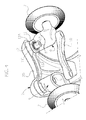
Figure 1 is a perspective view of an embodiment; -
Figure 2 is a perspective view of an embodiment; -
Figure 3 is a perspective view of an embodiment; -
Figure 4 is a perspective view of an embodiment; -
Figure 5 is an exploded view of an embodiment. - Illustrated in the ensuing description are various specific details aimed at an in-depth understanding of the embodiments. The embodiments can be obtained without one or more of the specific details, or with other methods, components, materials, etc. In other cases, known structures, materials, or operations are not illustrated or described in detail so that various aspects of the embodiments will not be obscured.
- Reference to "an embodiment" or "one embodiment" in the framework of this description is meant to indicate that a particular configuration, structure, or characteristic described in relation to the embodiment is comprised in at least one embodiment. Hence, phrases such as "in an embodiment" or "in one embodiment" that may be present in different points of this description do not necessarily refer to one and the same embodiment. Furthermore, particular conformations, structures, or characteristics can be combined adequately in one or more embodiments.
- The references used herein are provided merely for convenience and hence do not define the sphere of protection or the scope of the embodiments.
- In
Figure 1 , thereference number 1 designates a scooter according to one embodiment of the present invention. - It comprises a board 2 for resting of the feet of a user.
- The board 2 has a preferential direction of extension, corresponding, in operation, to the direction of the rectilinear motion of advance of the scooter. The board 2 moreover has one front end 2a mounted on which is a handlebar shaft 3. In the example illustrated in the figures, a tubular seat 4, fixed at the end 2a, is designed to receive the handlebar shaft 3, which is inserted by snap action within said seat. A pushbutton 5 enables decoupling of the handlebar shaft 3 from the seat 4.
- The board 2 has a
rear end 2b that identifies two longitudinal and substantially parallel arms 2c, which support in a freely rotatable way the rear wheel 6 set between them. - Mounted instead at the end 2a is a pair of
front wheels 7. - In particular, the end 2a has a generic half-shell conformation that identifies an inclined surface 2d, with a profile descending in a direction moving away from the rear end of the board 2. On said surface, pins 8 project from the underside of the board 2. The pins 8 define two steering axes 8' of the scooter and rotatably mounted thereon are the wheel supports 9. The steering axes 8' are inclined by an angle other than 90° with respect to the longitudinal direction of the board 2 so as to facilitate the manoeuvres for steering the means.
- In various embodiments, a connecting
bar 10 is hinged, at its opposite ends, to each of the wheel supports 9, in order to connect the movements of rotation of the two supports. - The supports 9 define respective axes 9' of rotation of the
wheels 7. - The
front wheels 7 are governed in a reciprocal position, which, when the scooter is being used, determines a substantially rectilinear motion of advance. In particular, the steering system described above comprises, for said purpose, elastic means operatively connected to the wheel supports. - In the aforesaid governed position, the supports 9 are oriented with respect to one another with their axes of rotation 9' substantially aligned to one another or else that deviate from a condition of mutual alignment for small angles of convergence or camber.
- In various embodiments, said elastic means comprise a torsion spring coaxially arranged on each of the two steering axes 8'.
- In various embodiments, a torsion spring is coaxially arranged on each of the two steering axes 8'.
- With particular reference to
Figures 3 ,4 , and5 , afirst sleeve 11 is set around the pin 8, fixed on abase 17, and has a substantially circular cross section such as to obtain an annular space between its internal walls and the pin 8 itself. - The wheel support 9 defines a
second sleeve 12 with substantially circular cross section, which can be fixed to the pin 8 so as to be freely rotatable with respect to said pin. Thesecond sleeve 12 has an internal undercut portion designed to define an annular space between its walls and the pin 8 itself. - The
sleeves torsion spring 13 is housed within said space so as to be almost completely closed from outside, by saidsleeves - The
spring 13 has two end portions 13', which extend in a direction parallel to the axial direction of the spring and in senses opposite to one another. The internal walls of thesleeves spring 13. - The relative arrangement between
sleeves spring 13 is such that the resting condition of the spring is made to correspond with a neutral position between thesleeves Figure 2 ). When the sleeves are displaced from their neutral position, thespring 13 intervenes according to an action that tends to bring the two sleeves back into said position. - In various embodiments, the
sleeves - In various embodiments, the
sleeve 11 comprises at its end edge an axial notch 11' extending for a given angular interval and delimited by two opposed radial walls 11a. - The
sleeve 12 has, instead, at the end edge a tooth 12', which, in the mounted condition of the two sleeves, sets itself in the notch 11', within which it is mobile. The opposed walls 11a constitute contrast surfaces upon which the tooth 12' bears and consequently determine the aforesaid angular end positions of thesleeves - In the neutral position of the sleeves, the tooth 12' is located at one and the same angular distance from both of the opposed walls 11a so as to define angular intervals of rotation of the sleeves, which are substantially the same for both of the directions of rotation.
- As emerges from the foregoing, the relative rotation that can be obtained between the
sleeves - Said limits render the scooter easier to control and hence less dangerous.
- In use, in fact, to carry out steering of the scooter, the board 2 must be inclined on the side towards which it is intended to curve. The inclination of the board means that the friction of the wheel against the ground produces a reaction torque on the supports 9 such as to cause rotation thereof with respect to the pin 8 and, hence, with respect to the board 2. The limitation obtained by the
sleeves - In various embodiments, a first sleeve and a second sleeve are coupled to respective end edges so that they can turn with respect to one another, and surround the pin that defines said first or second steering axis, thus obtaining an annular space with an axis substantially coinciding with said first or second axis, within which said torsion spring is housed.
- In various embodiments, the first and second sleeves can turn with respect to one another between two angular end positions.
- In various embodiments, the first sleeve comprises at its end edge an axial notch extending for a given angular interval and delimited by two opposed radial walls, and the second sleeve has at its end edge a tooth, which is mobile within said notch, the opposed radial walls of the notch identifying the aforesaid angular end positions of the sleeves.
- Of course, without prejudice to the principle of the invention, the details of construction and the embodiments may vary, even significantly, with respect to what has been illustrated herein purely by way of non-limiting example, without thereby departing from the scope of the invention, as defined by the annexed claims.
Claims (7)
- A vehicle comprising:- a resting board (2) for the feet of a user;- a first wheel support (9) and a second wheel support (9) for a pair of front and/or rear wheels, wherein said first wheel support (9) is mounted on said board so that it can turn about a first steering axis (8') and defines a first axis of rotation of the wheel (9'), and wherein said second wheel support (9) is mounted on said board so that it can turn about a second steering axis (8') and defines a second axis of rotation of the wheel (9');- elastic means operatively connected to the first and second supports for bringing said first and second supports in a reciprocal arrangement, which is designed to determine, in operation, a motion of advance of the vehicle that is substantially rectilinear,
said vehicle being characterized in that said elastic means comprise a torsion spring (13) arranged with its axis coinciding with one of said first and second steering axes. - The vehicle according to Claim 1, wherein a connection element (10) joins said first and second supports in rotation.
- The vehicle according to Claim 1, wherein a first sleeve (11) and a second sleeve (12) are coupled at respective end edges so that they can turn with respect to one another, and surround the pin (8) that defines said first or second steering axis (8'), thus obtaining an annular space with an axis substantially coinciding with said first or second steering axis, within which said torsion spring (13) is housed.
- The vehicle according to Claim 3, wherein said first and second sleeves can turn with respect to one another between two angular end positions.
- The vehicle according to Claim 4, wherein said first sleeve (11) comprises at its end edge an axial notch (11') extending for a given angular interval and delimited by two opposed radial walls (11a), and wherein said second sleeve (12) has at its end edge a tooth (12'), which is mobile within said notch, said opposed radial walls of said notch identifying said end positions of the sleeves.
- The vehicle according to any one of Claims 3 to 5, wherein the internal walls of said first and second sleeves each have a seat for housing one of the opposite ends of said spring.
- The vehicle according to any one of the preceding claims, wherein a torsion spring is coaxially arranged on each of said first and second steering axes.
Applications Claiming Priority (1)
| Application Number | Priority Date | Filing Date | Title |
|---|---|---|---|
| ITTO2010A000239A IT1399683B1 (en) | 2010-03-29 | 2010-03-29 | SCOOTER |
Publications (1)
| Publication Number | Publication Date |
|---|---|
| EP2371428A1 true EP2371428A1 (en) | 2011-10-05 |
Family
ID=43064493
Family Applications (1)
| Application Number | Title | Priority Date | Filing Date |
|---|---|---|---|
| EP11159898A Withdrawn EP2371428A1 (en) | 2010-03-29 | 2011-03-25 | Scooter |
Country Status (2)
| Country | Link |
|---|---|
| EP (1) | EP2371428A1 (en) |
| IT (1) | IT1399683B1 (en) |
Cited By (2)
| Publication number | Priority date | Publication date | Assignee | Title |
|---|---|---|---|---|
| WO2014121070A1 (en) * | 2013-02-01 | 2014-08-07 | Radio Flyer Inc. | User propelled ride-on vehicle |
| EP3132990A1 (en) * | 2015-08-11 | 2017-02-22 | Hillesheim, Björn | Golf cart |
Citations (4)
| Publication number | Priority date | Publication date | Assignee | Title |
|---|---|---|---|---|
| WO2000003773A1 (en) | 1998-07-13 | 2000-01-27 | Micro Mobility Systems Ag | Skateboard |
| DE20100372U1 (en) * | 2001-01-10 | 2001-03-29 | Lin Henkel | Scooter |
| US6382646B1 (en) * | 2001-01-24 | 2002-05-07 | Athony Shaw | Kick scooter steering control mechanism |
| DE102008006242A1 (en) * | 2008-01-25 | 2009-07-30 | Hudora Gmbh | Scooter or skateboard, has spring element pressurizing pivotably supported front wheels in center position, where spring element is arranged co-axial to connecting rod that is movably arranged at support element |
-
2010
- 2010-03-29 IT ITTO2010A000239A patent/IT1399683B1/en active
-
2011
- 2011-03-25 EP EP11159898A patent/EP2371428A1/en not_active Withdrawn
Patent Citations (4)
| Publication number | Priority date | Publication date | Assignee | Title |
|---|---|---|---|---|
| WO2000003773A1 (en) | 1998-07-13 | 2000-01-27 | Micro Mobility Systems Ag | Skateboard |
| DE20100372U1 (en) * | 2001-01-10 | 2001-03-29 | Lin Henkel | Scooter |
| US6382646B1 (en) * | 2001-01-24 | 2002-05-07 | Athony Shaw | Kick scooter steering control mechanism |
| DE102008006242A1 (en) * | 2008-01-25 | 2009-07-30 | Hudora Gmbh | Scooter or skateboard, has spring element pressurizing pivotably supported front wheels in center position, where spring element is arranged co-axial to connecting rod that is movably arranged at support element |
Cited By (7)
| Publication number | Priority date | Publication date | Assignee | Title |
|---|---|---|---|---|
| WO2014121070A1 (en) * | 2013-02-01 | 2014-08-07 | Radio Flyer Inc. | User propelled ride-on vehicle |
| CN104603002A (en) * | 2013-02-01 | 2015-05-06 | 瑞迪菲勒公司 | User propelled ride-on vehicle |
| US9108693B2 (en) | 2013-02-01 | 2015-08-18 | Radio Flyer Inc. | User propelled ride-on vehicle |
| JP2016509556A (en) * | 2013-02-01 | 2016-03-31 | ラジオ・フライヤー・インコーポレイテッドRadio Flyer, Inc. | User-propelled passenger vehicle |
| TWI576272B (en) * | 2013-02-01 | 2017-04-01 | 無線電飛輪公司 | User propelled ride-on vehicle |
| CN104603002B (en) * | 2013-02-01 | 2018-01-16 | 瑞迪菲勒公司 | User drives riding bicycle |
| EP3132990A1 (en) * | 2015-08-11 | 2017-02-22 | Hillesheim, Björn | Golf cart |
Also Published As
| Publication number | Publication date |
|---|---|
| IT1399683B1 (en) | 2013-04-26 |
| ITTO20100239A1 (en) | 2011-09-30 |
Similar Documents
| Publication | Publication Date | Title |
|---|---|---|
| KR200478090Y1 (en) | Head tube reset mechanism for a scooter | |
| KR101250018B1 (en) | A Front Wheel Steering Bike | |
| EP3299269B1 (en) | Electric self-balancing vehicle | |
| US9656709B2 (en) | Swing scooter | |
| US9108693B2 (en) | User propelled ride-on vehicle | |
| KR20150003813A (en) | A toy building set | |
| US11389739B2 (en) | Doll body motion accessory for recreational vehicles | |
| EP2604497A1 (en) | Scooter | |
| EP2371428A1 (en) | Scooter | |
| NL2006702C2 (en) | A bicycle front-wheel steering assembly. | |
| US20090315290A1 (en) | Multi-directional caster assembly | |
| WO2016094800A1 (en) | Scooter with mechanical assemblies | |
| EP2698309A1 (en) | Tricycle providing two riding modes | |
| EP2143472B1 (en) | Two-piece skateboard with flexible rear support member | |
| KR20170033361A (en) | Vehicle with spherical wheels | |
| KR20160023337A (en) | tricycle kick board | |
| KR101247098B1 (en) | A | |
| CN210149480U (en) | Steering balance mechanism of vehicle and balance vehicle | |
| WO2012102605A1 (en) | Human powered vehicle | |
| TWM539478U (en) | Three-wheel bicycle | |
| WO2014207774A1 (en) | Bicycle | |
| KR101207915B1 (en) | Steering device and vehicle having the same | |
| CN218577949U (en) | Scooter | |
| EP2870060B1 (en) | Tilting vehicle | |
| KR101735658B1 (en) | A non-powered tree circle kickboard |
Legal Events
| Date | Code | Title | Description |
|---|---|---|---|
| PUAI | Public reference made under article 153(3) epc to a published international application that has entered the european phase |
Free format text: ORIGINAL CODE: 0009012 |
|
| AK | Designated contracting states |
Kind code of ref document: A1 Designated state(s): AL AT BE BG CH CY CZ DE DK EE ES FI FR GB GR HR HU IE IS IT LI LT LU LV MC MK MT NL NO PL PT RO RS SE SI SK SM TR |
|
| AX | Request for extension of the european patent |
Extension state: BA ME |
|
| 17P | Request for examination filed |
Effective date: 20120330 |
|
| GRAP | Despatch of communication of intention to grant a patent |
Free format text: ORIGINAL CODE: EPIDOSNIGR1 |
|
| INTG | Intention to grant announced |
Effective date: 20140509 |
|
| STAA | Information on the status of an ep patent application or granted ep patent |
Free format text: STATUS: THE APPLICATION IS DEEMED TO BE WITHDRAWN |
|
| 18D | Application deemed to be withdrawn |
Effective date: 20140930 |