EP2371267A1 - Endoscope apparatus - Google Patents
Endoscope apparatus Download PDFInfo
- Publication number
- EP2371267A1 EP2371267A1 EP11152590A EP11152590A EP2371267A1 EP 2371267 A1 EP2371267 A1 EP 2371267A1 EP 11152590 A EP11152590 A EP 11152590A EP 11152590 A EP11152590 A EP 11152590A EP 2371267 A1 EP2371267 A1 EP 2371267A1
- Authority
- EP
- European Patent Office
- Prior art keywords
- observation
- light
- light source
- wavelength
- magnification
- Prior art date
- Legal status (The legal status is an assumption and is not a legal conclusion. Google has not performed a legal analysis and makes no representation as to the accuracy of the status listed.)
- Withdrawn
Links
Images





Classifications
-
- A—HUMAN NECESSITIES
- A61—MEDICAL OR VETERINARY SCIENCE; HYGIENE
- A61B—DIAGNOSIS; SURGERY; IDENTIFICATION
- A61B1/00—Instruments for performing medical examinations of the interior of cavities or tubes of the body by visual or photographical inspection, e.g. endoscopes; Illuminating arrangements therefor
- A61B1/00163—Optical arrangements
- A61B1/00188—Optical arrangements with focusing or zooming features
-
- A—HUMAN NECESSITIES
- A61—MEDICAL OR VETERINARY SCIENCE; HYGIENE
- A61B—DIAGNOSIS; SURGERY; IDENTIFICATION
- A61B1/00—Instruments for performing medical examinations of the interior of cavities or tubes of the body by visual or photographical inspection, e.g. endoscopes; Illuminating arrangements therefor
- A61B1/00002—Operational features of endoscopes
- A61B1/00004—Operational features of endoscopes characterised by electronic signal processing
- A61B1/00009—Operational features of endoscopes characterised by electronic signal processing of image signals during a use of endoscope
- A61B1/000094—Operational features of endoscopes characterised by electronic signal processing of image signals during a use of endoscope extracting biological structures
-
- A—HUMAN NECESSITIES
- A61—MEDICAL OR VETERINARY SCIENCE; HYGIENE
- A61B—DIAGNOSIS; SURGERY; IDENTIFICATION
- A61B1/00—Instruments for performing medical examinations of the interior of cavities or tubes of the body by visual or photographical inspection, e.g. endoscopes; Illuminating arrangements therefor
- A61B1/04—Instruments for performing medical examinations of the interior of cavities or tubes of the body by visual or photographical inspection, e.g. endoscopes; Illuminating arrangements therefor combined with photographic or television appliances
- A61B1/043—Instruments for performing medical examinations of the interior of cavities or tubes of the body by visual or photographical inspection, e.g. endoscopes; Illuminating arrangements therefor combined with photographic or television appliances for fluorescence imaging
-
- A—HUMAN NECESSITIES
- A61—MEDICAL OR VETERINARY SCIENCE; HYGIENE
- A61B—DIAGNOSIS; SURGERY; IDENTIFICATION
- A61B1/00—Instruments for performing medical examinations of the interior of cavities or tubes of the body by visual or photographical inspection, e.g. endoscopes; Illuminating arrangements therefor
- A61B1/06—Instruments for performing medical examinations of the interior of cavities or tubes of the body by visual or photographical inspection, e.g. endoscopes; Illuminating arrangements therefor with illuminating arrangements
- A61B1/063—Instruments for performing medical examinations of the interior of cavities or tubes of the body by visual or photographical inspection, e.g. endoscopes; Illuminating arrangements therefor with illuminating arrangements for monochromatic or narrow-band illumination
-
- A—HUMAN NECESSITIES
- A61—MEDICAL OR VETERINARY SCIENCE; HYGIENE
- A61B—DIAGNOSIS; SURGERY; IDENTIFICATION
- A61B1/00—Instruments for performing medical examinations of the interior of cavities or tubes of the body by visual or photographical inspection, e.g. endoscopes; Illuminating arrangements therefor
- A61B1/06—Instruments for performing medical examinations of the interior of cavities or tubes of the body by visual or photographical inspection, e.g. endoscopes; Illuminating arrangements therefor with illuminating arrangements
- A61B1/0638—Instruments for performing medical examinations of the interior of cavities or tubes of the body by visual or photographical inspection, e.g. endoscopes; Illuminating arrangements therefor with illuminating arrangements providing two or more wavelengths
-
- A—HUMAN NECESSITIES
- A61—MEDICAL OR VETERINARY SCIENCE; HYGIENE
- A61B—DIAGNOSIS; SURGERY; IDENTIFICATION
- A61B1/00—Instruments for performing medical examinations of the interior of cavities or tubes of the body by visual or photographical inspection, e.g. endoscopes; Illuminating arrangements therefor
- A61B1/06—Instruments for performing medical examinations of the interior of cavities or tubes of the body by visual or photographical inspection, e.g. endoscopes; Illuminating arrangements therefor with illuminating arrangements
- A61B1/0653—Instruments for performing medical examinations of the interior of cavities or tubes of the body by visual or photographical inspection, e.g. endoscopes; Illuminating arrangements therefor with illuminating arrangements with wavelength conversion
-
- A—HUMAN NECESSITIES
- A61—MEDICAL OR VETERINARY SCIENCE; HYGIENE
- A61B—DIAGNOSIS; SURGERY; IDENTIFICATION
- A61B1/00—Instruments for performing medical examinations of the interior of cavities or tubes of the body by visual or photographical inspection, e.g. endoscopes; Illuminating arrangements therefor
- A61B1/06—Instruments for performing medical examinations of the interior of cavities or tubes of the body by visual or photographical inspection, e.g. endoscopes; Illuminating arrangements therefor with illuminating arrangements
- A61B1/0655—Control therefor
-
- A—HUMAN NECESSITIES
- A61—MEDICAL OR VETERINARY SCIENCE; HYGIENE
- A61B—DIAGNOSIS; SURGERY; IDENTIFICATION
- A61B1/00—Instruments for performing medical examinations of the interior of cavities or tubes of the body by visual or photographical inspection, e.g. endoscopes; Illuminating arrangements therefor
- A61B1/06—Instruments for performing medical examinations of the interior of cavities or tubes of the body by visual or photographical inspection, e.g. endoscopes; Illuminating arrangements therefor with illuminating arrangements
- A61B1/0661—Endoscope light sources
- A61B1/0684—Endoscope light sources using light emitting diodes [LED]
-
- A—HUMAN NECESSITIES
- A61—MEDICAL OR VETERINARY SCIENCE; HYGIENE
- A61B—DIAGNOSIS; SURGERY; IDENTIFICATION
- A61B1/00—Instruments for performing medical examinations of the interior of cavities or tubes of the body by visual or photographical inspection, e.g. endoscopes; Illuminating arrangements therefor
- A61B1/06—Instruments for performing medical examinations of the interior of cavities or tubes of the body by visual or photographical inspection, e.g. endoscopes; Illuminating arrangements therefor with illuminating arrangements
- A61B1/07—Instruments for performing medical examinations of the interior of cavities or tubes of the body by visual or photographical inspection, e.g. endoscopes; Illuminating arrangements therefor with illuminating arrangements using light-conductive means, e.g. optical fibres
Definitions
- the center emission wavelength of the special light source is a wavelength (405 nm) for emphasizing a fine blood vessel structure of a living body tissue surface layer as an observation subject. That is, when it is desired to perform short-range-view observation of fine blood vessels, the special light wavelength for emphasizing a fine blood vessel structure of a living body tissue surface layer is set automatically, that is, the illumination light wavelength that is suitable for a manipulation magnification value is set automatically.
- the excitation emission efficiency of the phosphor 59 is lower for the violet laser light which is guided by the optical fiber 57B than for the blue laser light, the proportion of violet laser light that passes through the phosphor 59 is larger than that of blue laser light.
- the violet laser light causes the phosphor 59 to emit fluorescent light having lower intensity through excitation than the blue laser light does.
- Violet laser light that passes through the phosphor 59 serves as narrow-wavelength-band illumination light.
- Each phosphor 59 contains plural kinds of phosphor substances (e.g., YAG phosphor or BAM (BaMgAl 10 O 17 )) that are excited when absorbing part of blue laser light and emit green to yellow light.
- White (quasi-white) illumination light is generated as a combination of green to yellow light emitted through excitation by part of blue laser light and the other part of the blue laser light that passes through the phosphor 59 without being absorbed.
- the semiconductor light-emitting devices are used as the excitation light sources, high-intensity white light can be obtained with high emission efficiency, the intensity of white light can be adjusted easily, and variations in color temperature and chromaticity of white light can be made small.
- Fig. 5 is a flowchart of a procedure of varying the emission light quantity ratio according to the observation magnification.
- Table 1 shows example light quantity ratio-observation magnification conversion information.
- the ratio of the light quantity of the violet laser light source 49 to that of the blue laser light source 47 is set at 2:1, for example, in a distant-view observation mode in which the observation magnification is low, and at 10:1, for example, in a short-range-view observation mode in which the observation magnification is high.
- Observation magnification Mode Light quantity ratio R LD2 (405 nm):LD1 (445 nm) Low Distant-view observation 2:1 High Short-range-view observation 10:1
- the endoscope apparatus 100 has a function of properly displaying, according to an observation magnification value, in the form of an estimated spectral image, living body information that cannot be obtained from ordinary observation images; for example, the endoscope apparatus 100 can emphasize a lesion and a fine structure of new blood vessels formed in a mucosa layer or a mucosa lower layer.
- the endoscope apparatus 100 can provide optimum image information for an observation subject in synchronism with a variation in observation magnification by performing proper image processing such as emphasis processing according to the observation magnification.
- the processor 45 of the endoscope apparatus 100 is equipped with an estimated spectral image generating section 69 (estimated spectral image generating means), a parameter database 73, and a switching section 75.
- a signal of an endoscope observation image that is output from the imaging device 21 is converted by the A/D converter 77 into a digital signal, which is captured by the processor 45 and input to the control section 63.
- the estimated spectral image generating section 69 generates an estimated spectral image SP by performing a matrix operation involving matrix parameters M on the endoscope observation image P.
- the details of an example operation of the estimated spectral image generating section 69 are described in JP-A-2003-93336 .
- the estimated spectral image generating section 69 generates an estimated spectral image SP by performing a matrix operation involving matrix parameters M according to the following Equation (1).
- SP r , SPg, and SP b are the R, G, and B components of the estimated spectral image SP
- P r , Pg, and P b are the R, G, and B components of the endoscope observation image P
- M 00 -M 22 are the matrix parameters M ij of the 3x3 matrix for the matrix operation.
- matrix parameters M in the following Equation (2) which consist of matrix parameters (coefficients) p21 for the center wavelength 500 nm, matrix parameters (coefficients) p45 for the center wavelength 620 nm, and matrix parameters (coefficients) p51 for the center wavelength 650 nm among the 61 sets of matrix parameters shown in Fig. 8 are used as the matrix parameters (M 00 , M 01 , M 02 ), (M 10 , M 11 , M 12 ), and (M 20 , M 21 , M 22 ), respectively.
- Formula 2 M 00 M 01 M 02 M 10 M 11 M 12 M 20 M 21 M 22 - 0.00119 0.002346 0.0016 0.004022 0.000068 - 0.00097 0.005152 - 0.00192 0.000088
- Sets of parameters are stored in the parameter database 73 for respective parts to be observed such as blood vessels and living body tissue, and an estimated spectral image SP is generated using sets of parameters suitable for a target part.
- Table 2 shows example wavelength sets each for setting matrix parameters M. [Table 2] No.
- the endoscope apparatus 100 may have a function of adjusting the gains of R, G, and B components using correction values that accord with sensitivity characteristics of the imaging device 21 of an individual product of the endoscope main body 11. More specifically, the estimated spectral image generating section 69 generates an estimated spectral image SP using, instead of the matrix parameters M of Equation (1), matrix parameters M1 obtained by multiplexing the matrix of the matrix parameters M by the matrix including R, G, and B gain coefficients Rg, Gg, and Bg according to the following Equation (3).
- Equation (3) Equation (3)
- the gain coefficients Rg, Gg, and Bg are changed according to the sensitivity characteristics of the imaging device 21 which are stored in, for example, a product identification memory (not shown) provided in the endoscope main body 11 used.
- a product identification memory not shown
- R, G, and B component values suitable for brightness can be obtained and hence the image quality of an estimated spectral image is enhanced.
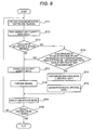
- Fig. 9 is a flowchart of a procedure of varying the emission light quantity ratio according to the observation magnification in an observation with generation of an estimated spectral image.
- the endoscope apparatus 100 can generate an estimated spectral image corresponding to a desired wavelength set and use it as an observation image. A procedure of generating an estimated spectral image in the endoscope apparatus 100 will be described below.
- an emission light quantity ratio value is read out at step ST12.
- step ST13 it is judged whether or not the wavelength set switching button has been pressed. If the wavelength set switching button has been pressed, it is judged at step ST14 whether not the wavelength range of a spectrum of light produced by the blue laser light source 47 and the violet laser light source 49 having the read-out emission light quantity ratio overlaps with that of a new wavelength set.
- An estimated spectral image may be generated from an image taken by lighting both of the white illumination light source and the special light source. This makes it possible to increase the amount of information of an estimated spectral image by necessarily leaving a wavelength component of the special light source (405 nm).
- the illuminating means is not limited to the above one and may be configured as described below.
- Fig. 10 is a block diagram showing the configuration of a modified light source apparatus having a white light source and a laser light source.
- the modified light source apparatus 43a is equipped with an illumination system for outputting light that is emitted from a white light source 91 and transmitted by a fiber bundle 93 consisting of many optical fibers and an illumination system for outputting light that is emitted from a laser light source 95, is guided by a single optical fiber 97, and passes through a diffusion plate 99.
- Fig. 12 is a block diagram showing the configuration of a modified light source apparatus having a white light source and a rotary filter device.
- the light source apparatus 43c R, G, and B light beams, narrow-band light, C, M, and Y light beams, or C, M, Y, and G light beams are extracted from light emitted from a white light source 91 by using a rotary filter device 105.
- the observation image can be varied continuously as the observation magnification is varied by a zoom magnification varying manipulation so that an observation image suitable for an endoscope diagnosis is obtained at each observation magnification, whereby the operator can be prevented from feeling uncomfortable and the accuracy of a diagnosis can be increased.
Landscapes
- Health & Medical Sciences (AREA)
- Life Sciences & Earth Sciences (AREA)
- Surgery (AREA)
- Engineering & Computer Science (AREA)
- Physics & Mathematics (AREA)
- Optics & Photonics (AREA)
- Biomedical Technology (AREA)
- General Health & Medical Sciences (AREA)
- Pathology (AREA)
- Nuclear Medicine, Radiotherapy & Molecular Imaging (AREA)
- Biophysics (AREA)
- Heart & Thoracic Surgery (AREA)
- Medical Informatics (AREA)
- Molecular Biology (AREA)
- Animal Behavior & Ethology (AREA)
- Radiology & Medical Imaging (AREA)
- Public Health (AREA)
- Veterinary Medicine (AREA)
- Microelectronics & Electronic Packaging (AREA)
- Signal Processing (AREA)
- Endoscopes (AREA)
- Instruments For Viewing The Inside Of Hollow Bodies (AREA)
- Closed-Circuit Television Systems (AREA)
Abstract
Description
- The present invention relates to an endoscope apparatus.
- Usually, a white light source is used in endoscope apparatus. However, in recent years, endoscope apparatus that enable special light observation such as narrow-band light observation in which a fine structure of a surface layer of mucosa tissue is emphasized with illumination by light in a particular narrow wavelength band (narrow-band light) and fluorescence observation in which fluorescence emitted from a fluorescent substance given in advance or living body tissue have come to be used (refer to
JP-B-3,583,731 - In diagnoses using an endoscope apparatus, to find a lesion, it is effective to examine a distant-view image covering a wide range that is taken by wide-angle shooting. And to observe the thus-found lesion, it is effective to examine a short-range-view image taken by enlarged shooting. White light is mainly used for the distant-view observation and narrow-band special light is used for the short-range-view observation to emphasize a fine structure or a lesion. The light source type used is switched in synchronism with an observation magnification change which is caused by a zoom magnification varying manipulation (refer to
JP-A-2007-20728 - However, where switching is merely made between white light and special light depending on whether short-range-view shooting or distant-view shooting is being performed, the manner of image display is not varied continuously in link with a zoom magnification varying manipulation. Instead, the illumination light is switched from white light to special light at a particular observation magnification value and the content of the observation image is changed suddenly, which is uncomfortable to the operator. Furthermore, the illumination light cannot be adjusted finely to attain optimum illumination according to the observation magnification.
- An object of the present invention is to provide an endoscope apparatus in which the observation image can be varied continuously as the observation magnification is varied by a zoom magnification varying manipulation so that an observation image suitable for an endoscope diagnosis is obtained at each observation magnification, and to thereby prevent the operator from feeling uncomfortable and increase the accuracy of a diagnosis.
- (1) According to an aspect of the invention, an endoscope apparatus includes: an illuminating unit having plural light sources which generate light beams having different spectra, which illuminates an observation subject; an imaging unit which images the observation subject; an observation magnification varying unit which varies observation magnification of the imaging of the imaging unit; and a light quantity ratio varying unit which continuously varies an emission light quantity ratio between the plural light sources according to the observation magnification that is set by the observation magnification varying unit.
- In the endoscope apparatus according to the embodiment, the observation image can be varied continuously as the observation magnification is varied by a zoom magnification varying manipulation so that an observation image suitable for an endoscope diagnosis is obtained at each observation magnification, whereby the operator is prevented from feeling uncomfortable and the accuracy of a diagnosis can be increased.
-
-
Fig. 1 is a conceptual block diagram showing the configuration of an endoscope apparatus according to an embodiment of the present invention. -
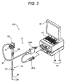
Fig. 2 shows an appearance of an example of the endoscope apparatus ofFig. 1 . -
Fig. 3 is a graph showing example spectra of illuminating means. -
Fig. 4 schematically shows example observation images displayed by the endoscope apparatus. -
Fig. 5 is a flowchart of a procedure of varying the emission light quantity ratio according to the observation magnification. -
Fig. 6 is a graph showing a relationship between the observation magnification and the light quantity ratio. -
Fig. 7 shows an AE program diagram having the observation magnification as a parameter. -
Fig. 8 is a table showing example sets of matrix parameters that are stored in a parameter database of a processor shown inFig. 1 . -
Fig. 9 is a flowchart of a procedure of varying the emission light quantity ratio according to the observation magnification in an observation with generation of an estimated spectral image. -
Fig. 10 is a block diagram showing the configuration of a modified light source apparatus which is equipped with a white light source and a laser light source. -
Fig. 11 is a block diagram showing the configuration of a modified light source apparatus which is equipped with LEDs and a laser light source. -
Fig. 12 is a block diagram showing the configuration of a modified light source apparatus which is equipped with a white light source and a rotary filter device. - An embodiment of the present invention will be hereinafter described with reference to the drawings.
-
Fig. 1 is a conceptual block diagram showing the configuration of an endoscope apparatus according to the embodiment of the invention.Fig. 2 shows an appearance of an example of the endoscope apparatus ofFig. 1 . - As shown in
Figs. 1 and2 , theendoscope apparatus 100 is equipped with an endoscopemain body 11 and acontrol apparatus 13 to which the endoscopemain body 11 is connected. Adisplay unit 15 for displaying image information etc. and aninput unit 17 for receiving an input manipulation are connected to thecontrol apparatus 13. The endoscopemain body 11 is an electronic endoscope which has an illumination optical system for emitting illumination light from a tip portion of anendoscope insertion unit 19 and an imaging optical system including an imaging device 21 (imaging means; seeFig. 1 ) for imaging an observation region and anobjective lens unit 39 which is a variable magnification optical system. - The endoscope
main body 11 is equipped with theendoscope insertion unit 19 to be inserted into a subject body, a manipulation unit 25 (seeFig. 2 ) which is connected to theendoscope insertion unit 19 via anintermediate portion 23 and used for performing a manipulation for curving the tip portion of theendoscope insertion unit 19 and a manipulation for observation, andconnector units main body 11 to thecontrol apparatus 13 detachably via auniversal cable 27. Although not shown inFig. 1 or2 , various channels such as a forceps channel through which to insert a tissue picking tool or the like and an air/water feed channel are formed inside themanipulation unit 25 and theendoscope insertion unit 19. - The
endoscope insertion unit 19 is composed of a flexiblesoft portion 31, abendable portion 33, and a tip portion (hereinafter also referred to as an endoscope tip portion) 35. As shown inFig. 1 ,illumination windows imaging device 21 such as a CCD (charge-coupled device) image sensor or a CMOS (complementary metal-oxide-semiconductor) image sensor for acquiring image information from the observation region are arranged in theendoscope tip portion 35. The above-mentionedobjective lens unit 39 is disposed adjacent to the photodetecting surface of theimaging device 21. - The
bendable portion 33, which is located between thesoft portion 31 and thetip portion 35, can be bent freely by a manipulation of rotatingangle knobs 41 which are provided in themanipulation unit 25. Thebendable portion 33 can be bent to any direction at any angle according to, for example, a part to be observed of a subject body by the endoscopemain body 11, whereby the illumination/observation direction of theillumination windows imaging device 21 provided in theendoscope tip portion 35 can be directed to a desired part to be observed. Although not shown inFigs. 1 and2 , theillumination windows endoscope tip portion 35 are provided with cover glasses and lenses. - The
control apparatus 13 is equipped with a light source apparatus 43 (illuminating means) for generating illumination light to be supplied to theillumination windows endoscope tip portion 35 and a processor 45 (endoscope image processing device) for performing image processing on an image signal that is supplied from theimaging device 21. Thecontrol apparatus 13 is connected to the endoscopemain body 11 by theconnector units display unit 15 andinput unit 17 are connected to theprocessor 45. Theprocessor 45 performs image processing on an image signal that is transmitted from the endoscopemain body 11, generates a display image, and supplies it to thedisplay unit 15 according to an instruction that is supplied from themanipulation unit 25 of the endoscopemain body 11 or theinput unit 17. - The
light source apparatus 43 is equipped with a blue laser light source (semiconductor light-emitting device, white illumination light source) 47 having a center wavelength 445 nm and an violet laser light source (semiconductor light-emitting device, special light source) 49 having a center wavelength 405 nm. Light emitting operations of thelight sources source control section 51, whereby the light quantity ratio between light emitted from the bluelaser light source 47 and light emitted from the violetlaser light source 49 can be changed in a desired manner. The center emission wavelength of the special light source should be in a range of 370 to 470 nm. The lower limit value 370 nm facilitates acquisition of a semiconductor light-emitting device on the market. The upper limit value 470 nm makes it possible to produce illumination light in a wavelength range that is suitable for narrow-band light observation with emphasis on a fine structure of a surface layer of mucosa tissue. - In the embodiment, the center emission wavelength of the special light source is a wavelength (405 nm) for emphasizing a fine blood vessel structure of a living body tissue surface layer as an observation subject. That is, when it is desired to perform short-range-view observation of fine blood vessels, the special light wavelength for emphasizing a fine blood vessel structure of a living body tissue surface layer is set automatically, that is, the illumination light wavelength that is suitable for a manipulation magnification value is set automatically.
- Each of the blue
laser light source 47 and the violetlaser light source 49 may be a broad-area-type InGaN laser diode, and may also be an InGaNAs laser diode or a GaNAs laser diode. Alternatively, each light source may be another type of light-emitting device such as a light-emitting diode. - Laser beams emitted from the
light sources connector unit 29A via a combiner (multiplexer) 53 and a coupler (demultiplexer) 55. However, the invention is not limited to this structure; laser beams emitted from thelight sources connector unit 29A without using thecombiner 53 and thecoupler 55. -
Fig. 3 is a graph showing example spectra of the illuminating means. The blue laser light excites a phosphor 59 (wavelength conversion member) disposed at the light emission end of theoptical fiber 57A of theendoscope tip portion 35 and thereby causes thephosphor 59 to emit fluorescent light. That is, the white illumination light source is formed by the semiconductor light-emitting device and the wavelength conversion member including thephosphor 59 which is excited at the emission wavelength of the semiconductor light-emitting device. Light emitted from the semiconductor light-emitting device excites thephosphor 59 to cause it to emit fluorescent light, whereby white light is obtained. Part of the blue laser light passes through thephosphor 59. On the other hand, since the excitation emission efficiency of thephosphor 59 is lower for the violet laser light which is guided by theoptical fiber 57B than for the blue laser light, the proportion of violet laser light that passes through thephosphor 59 is larger than that of blue laser light. On the longer wavelength side, the violet laser light causes thephosphor 59 to emit fluorescent light having lower intensity through excitation than the blue laser light does. Violet laser light that passes through thephosphor 59 serves as narrow-wavelength-band illumination light. - With the light-source-related configuration of the embodiment, mixing illumination light of the blue laser light having the center wavelength 445 nm and illumination light of the violet laser light having the center wavelength 405 nm improves the color tone of white light because a wavelength component in a wavelength range of 460 to 470 nm that is insufficient in the illumination light of the blue laser light having the center wavelength 445 nm is compensated for by the same wavelength component of the illumination light of the violet laser light having the center wavelength 405 nm.
- As such, the
light source apparatus 43 has the white illumination light source and the special light source which produces illumination light that is different than the white illumination light source does. Thecontrol section 63 performs such a control as to increase the ratio of the emission light quantity of the special light source (i.e., ultraviolet laser light source 49) to that of the white illumination light source as the observation magnification increases. As a result, as the degree of short-range-view observation becomes higher, the emission light quantity of the special light source is increased and hence a narrow-band light observation image obtained with illumination by the narrow-band light having the particular wavelength is emphasized more. - Each of the
optical fibers - Each
phosphor 59 contains plural kinds of phosphor substances (e.g., YAG phosphor or BAM (BaMgAl10O17)) that are excited when absorbing part of blue laser light and emit green to yellow light. White (quasi-white) illumination light is generated as a combination of green to yellow light emitted through excitation by part of blue laser light and the other part of the blue laser light that passes through thephosphor 59 without being absorbed. In the embodiment, since the semiconductor light-emitting devices are used as the excitation light sources, high-intensity white light can be obtained with high emission efficiency, the intensity of white light can be adjusted easily, and variations in color temperature and chromaticity of white light can be made small. - The
phosphors 59 can prevent superimposition of imaging-obstructive noise or occurrence of a flicker at the time of display of a moving image which would otherwise be cause by a speckle pattern that is produced due to the coherence of laser light. It is preferable that the phosphor substances constituting thephosphors 59 and a fixing/solidifying resin (filler) have such particle diameters as to be low in absorption and high in scattering for infrared light taking their differences in refractive index into consideration. This enhances the scattering effect and lowers the optical loss without decrease in light intensity for red light or infrared light. That is, high-intensity white light can be obtained with high efficiency. -
Fig. 4 schematically shows example observation images displayed by theendoscope apparatus 100. - When illumination light enters living body tissue, the incident light travels through the living body tissue diffusely. The absorption/scattering characteristics of living body tissue depend on the wavelength; that is, the scattering becomes stronger as the wavelength becomes shorter. Therefore, the depth reached by illumination light depends on its wavelength. On the other hand, blood flowing through a blood vessel has an absorption peak in a wavelength range of 400 to 420 nm and high contract is obtained in that wavelength range. For example, blood vessel information of capillary vessels of a mucosa surface layer is obtained by illumination light in a wavelength range around 400 nm, and blood vessel information of blood vessels including ones located in a deeper layer is obtained by illumination light in a wavelength range around 500 nm. Therefore, for observation of blood vessels in a surface layer of living body tissue, a light source having a center wavelength 360 to 800 nm, preferably 365 to 515 nm and even preferably 400 to 470 nm, is used.
- As shown in
Fig. 4 , in an observation image obtained using white illumination light, whereas images of blood vessels located in a relatively deep mucosa layer can be obtained, fine capillary vessels in a mucosa surface layer are blurred. On the other hand, in an observation image obtained using narrow-band illumination light having only a short wavelength, fine capillary vessels in the mucosa surface layer can be seen clearly. - In the
endoscope apparatus 100, the light quantity ratio between the bluelaser light source 47 and the violet laser light source is variable. The light quantity ratio is varied by thecontrol section 63 shown inFig. 1 and blood vessels in a mucosa surface layer are emphasized in an image to facilitate their observation. Where the blue laser light component of the bluelaser light source 47 is dominant, illumination light is produced in which a white light component as a combination of blue laser light and light emitted from thephosphor 59 through excitation is dominant and an observation image like the white light observation image shown inFig. 4 is obtained. However, since the blue laser light is mixed in the illumination light, capillary blood vessels in a surface layer is emphasized in the observation image. - Where the violet laser light component of the violet
laser light source 49 is dominant, an observation image like the narrow-band light observation image shown inFig. 4 is obtained. Fine capillary vessels in a mucosa surface layer can be observed in such a manner as to continue to be displayed in an emphasized manner by varying the light quantity ratio between the light beams emitted from the bluelaser light source 47 and the violet laser light source (i.e., varying the proportion of the violet laser light component in the entire illumination light). - As the proportion of the violet laser light component increases, fine capillary vessels in a mucosa surface layer which is thin in the depth direction are shown more clearly in an observation image. As the proportion of the violet laser light component decreases, information of blood vessels located in a thicker region from the mucosa surface layer to its deep layer are shown. In this manner, a blood vessel distribution in the depth direction from the mucosa surface layer can be displayed in an emphasized manner and the blood vessel information of an observation part can be extracted as continuous pieces of information corresponding to respective depth ranges. In particular, in the embodiment, since blood vessel information extracted by blue laser light and blood vessel information of a surface layer extracted by violet laser light can be compared with each other through image display, information of blood vessels including the ones located in the surface layer can be observed with increased legibility.
- Incidentally, the
objective lens unit 39 of theendoscope apparatus 100 is provided with a magnification-varying movable lens (not shown). The magnification-varying movable lens is incorporated in theobjective lens unit 39 in a movable manner and thereby serves to vary the observation magnification. Theobjective lens unit 39 is also provided, separately from the magnification-varying movable lens, with a focus-adjusting movable lens (not shown) for performing an auto-focus function. The magnification-varying movable lens is driven via a zoom control section 81 (observation magnification varying means) according to a manipulation on azoom switch 83. - The
endoscope apparatus 100 is provided with a light quantity varying means for varying the light quantity ratio between light beams emitted from the plural light sources according to an observation magnification value that is set by thezoom control section 81. For example, the light quantity varying means is a program stored in astorage unit 65. The light quantity varying means the light quantity ratio between the bluelaser light source 47 and the violetlaser light source 49 by referring to a magnification detection signal that is supplied from thezoom control section 81. A resulting light quantity ratio control signal is supplied to the lightsource control section 51. The observation magnification value may be an enlargement value of digital zoom processing. In this case, an enlargement value of image processing for enlarging shot image information is used as an observation magnification value. -
Fig. 5 is a flowchart of a procedure of varying the emission light quantity ratio according to the observation magnification. - As the operator varies the observation magnification in a direction from distant-view observation to short-range-view observation or vice versa by a zoom magnification varying manipulation (ST1), each resulting magnification detection signal is detected by the
zoom control section 81 and input to a light quantity ratio varying means. At step ST2, every time the light quantity ratio varying means receives a magnification detection signal, the light quantity ratio varying means reads a corresponding emission light quantity ratio between the bluelaser light source 47 and the violetlaser light source 49 from light quantity ratio-observation magnification conversion information stored in thestorage unit 65 and performs updating. - The following Table 1 shows example light quantity ratio-observation magnification conversion information. The ratio of the light quantity of the violet
laser light source 49 to that of the bluelaser light source 47 is set at 2:1, for example, in a distant-view observation mode in which the observation magnification is low, and at 10:1, for example, in a short-range-view observation mode in which the observation magnification is high.[Table 1] Observation magnification Mode Light quantity ratio R LD2 (405 nm):LD1 (445 nm) Low Distant-view observation 2:1 High Short-range-view observation 10:1 -
Fig. 6 is a graph showing a relationship between the observation magnification and the light quantity ratio. The proportion of the light quantity of the bluelaser light source 47 is increased as the degree of distant-view observation increases (i.e., the observation magnification decreases), and the proportion of the light quantity of the violetlaser light source 49 is increased as the degree of short-range-view observation increases (i.e., the observation magnification increases). For example, the light quantity ratio-observation magnification conversion information is stored as a preset function equation. That is, a function representing the curve shown inFig. 6 is determined in advance. In this case, emission light quantity ratio values can be determined continuously for arbitrary observation magnification values. - Upon reading of the emission light quantity ratio, at step ST3 the light quantity ratio varying means supplies the
light control section 51 with a control signal for changing the light quantity ratio between the bluelaser light source 47 and the violetlaser light source 49. Imaging is performed at step ST4. An endoscope observation image signal that is output from theimaging device 21 is converted by an A/D converter 77 shown inFig. 1 into a digital signal, which is supplied to secondary circuits headed by apreprocessing section 67. Thepreprocessing section 67 is to perform preprocessing on an endoscope observation image signal and has a function of converting the digital endoscope observation image signal into a signal of the RGB primary color system if the former is of the CMY or CMYG complementary color system, a gamma conversion function, a gradation adjusting function, and other functions. The endoscope observation image signal as processed by thepreprocessing section 67 is supplied to theimage processing section 71 and displayed on thedisplay unit 15 at step ST5. At step ST6, the display on thedisplay unit 15 is finished upon input of an observation end signal. - As described above, in the
endoscope apparatus 100, the light quantity ratio between light beams emitted from the plural light sources is varied continuously by the light quantity ratio varying means as the observation magnification is varied. This prevents a sudden change in the content of an observation image. -
Fig. 7 shows an AE program diagram having the observation magnification as a parameter. Thecontrol section 63 automatically sets the shutter speed, the aperture, etc. according to the observation magnification using the AE program diagram, and thereby compensates for a camera shake in an enlarged observation. As shown inFig. 7 , each exposure value (EV value) is represented by a bottom-left-to-top-right diagonal equivalent line. The horizontal axis represents the shutter speed and the vertical axis represents the aperture. InFig. 7 , the broken-line curve corresponds to distant-view observation and the solid-line curve corresponds to short-range-view observation (enlarged observation). When a subject is bright, correct exposure is obtained by evenly adjusting the aperture and the shutter speed. When a subject is sufficiently bright, the lens aperture is set at a minimum value and the exposure is adjusted by the shutter speed. In enlarged observation, a signal indicating a position of the magnification-varying movable lens is supplied from the zoon control section 81 (seeFig. 1 ) to thecontrol section 63, and thecontrol section 63 adjusts the shutter speed according to a curve corresponding to an observation magnification value employed. The curve for enlarged observation is shifted rightward from that for distant-view observation. As a result, in enlarged observation in which the observation magnification is large, the curve with faster shutter speeds is used and hence a control is performed so as to make influence of a camera shake less conspicuous. - The
endoscope apparatus 100 has a function of properly displaying, according to an observation magnification value, in the form of an estimated spectral image, living body information that cannot be obtained from ordinary observation images; for example, theendoscope apparatus 100 can emphasize a lesion and a fine structure of new blood vessels formed in a mucosa layer or a mucosa lower layer. - Color imbalance occurs when the emission light quantity ratio is varied in the above-described manner. Therefore, it is preferable to maintain the color tone of the entire observation image by varying the degrees of spectral corrections for the respective colors according to a variation in emission light quantity ratio. The
endoscope apparatus 100 can provide optimum image information for an observation subject in synchronism with a variation in observation magnification by performing proper image processing such as emphasis processing according to the observation magnification. - To process an endoscope observation image acquired by the endoscope
main body 11, theprocessor 45 of theendoscope apparatus 100 is equipped with an estimated spectral image generating section 69 (estimated spectral image generating means), aparameter database 73, and aswitching section 75. - A procedure of generating an estimated spectral image in the
endoscope apparatus 100 will be described below. - A signal of an endoscope observation image that is output from the
imaging device 21 is converted by the A/D converter 77 into a digital signal, which is captured by theprocessor 45 and input to thecontrol section 63. - If the operator wants to view an estimated spectral image rather than an ordinary image, the operator gives an instruction by manipulating a wavelength set
switching button 79 or the like of themanipulation unit 25 of the endoscopemain body 11. If observation using an estimated spectral image is commanded, the endoscope observation image signal as subjected to the preprocessing in thepreprocessing section 67 is supplied to the estimated spectralimage generating section 69, where it is subjected to spectral estimation processing. - The estimated spectral
image generating section 69 generates an estimated spectral image SP by performing a matrix operation involving matrix parameters M on the endoscope observation image P. The details of an example operation of the estimated spectralimage generating section 69 are described inJP-A-2003-93336 - More specifically, the estimated spectral
image generating section 69 generates an estimated spectral image SP by performing a matrix operation involving matrix parameters M according to the following Equation (1).
- In Equation (1), SPr, SPg, and SPb are the R, G, and B components of the estimated spectral image SP, Pr, Pg, and Pb are the R, G, and B components of the endoscope observation image P, and M00-M22 are the matrix parameters Mij of the 3x3 matrix for the matrix operation.
-
Fig. 8 is a table showing example sets of matrix parameters that are stored in theparameter database 73 of theprocessor 45. - As shown in
Fig. 8 , matrix parameter sets pn = (Mi0, Mi1, Mi2) (n = 1 to 61, i (= 0, 1, or 2) represents a row of the matrix of the matrix parameters M) for respective wavelength ranges that, for example, cover awavelength range 400 to 700 nm and are separated from each other by 5 nm are stored in theparameter database 73. For example, if 500 nm, 620 nm, and 650 nm are selected as a set of wavelengths λ1, λ2, and λ3 for the estimated spectral image SP, matrix parameters M in the following Equation (2) which consist of matrix parameters (coefficients) p21 for thecenter wavelength 500 nm, matrix parameters (coefficients) p45 for the center wavelength 620 nm, and matrix parameters (coefficients) p51 for thecenter wavelength 650 nm among the 61 sets of matrix parameters shown inFig. 8 are used as the matrix parameters (M00, M01, M02), (M10, M11, M12), and (M20, M21, M22), respectively.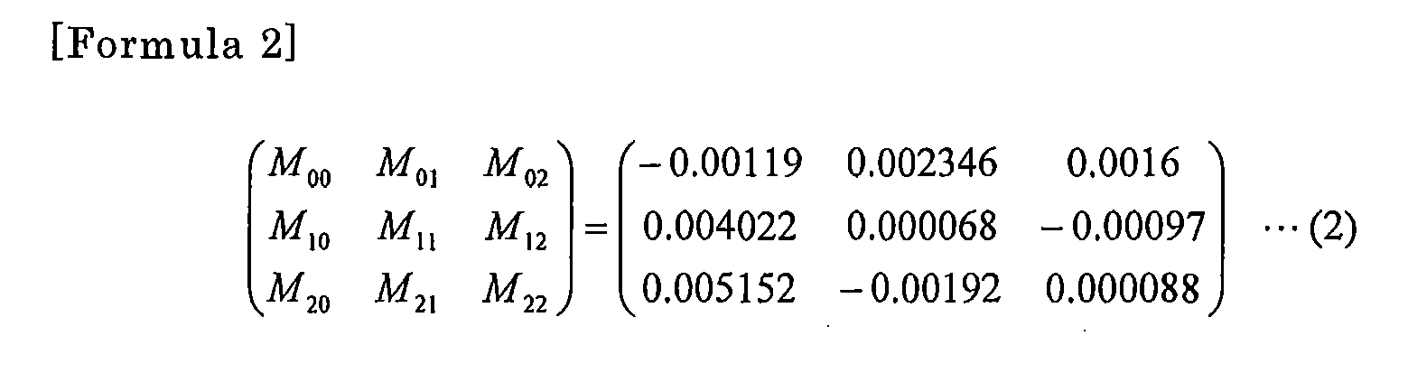
- Sets of parameters are stored in the
parameter database 73 for respective parts to be observed such as blood vessels and living body tissue, and an estimated spectral image SP is generated using sets of parameters suitable for a target part. Table 2 shows example wavelength sets each for setting matrix parameters M.[Table 2] No. Type λ1, λ2, λ3 (nm) CH1 Standard set 400, 500, 600 CH2 Blood vessel set 470, 500, 670 CH3 Blood vessel set 475, 510, 685 CH5 Set for imaging of particular tissue 440, 480, 520 CH6 Set for imaging of particular tissue 480, 510, 580 CH7 Hemoglobin set for discrimination between oxyhemoglobin and deoxyhemoglobin 400, 430, 475 CH8 Blood-carotene set for discrimination between blood and carotene 415, 450, 500 CH9 Blood-cytoplasm set for discrimination between blood and cytoplasm 420, 550, 600 - The estimated spectral
image generating section 69 performs a matrix operation on a shot image that is taken by illuminating an observation subject with white illumination light and thereby generates an estimated spectral image that would be obtained when the observation subject were illuminated with light having a spectrum that is obtained by a wavelength set that is set by the wavelength set setting means. Thecontrol section 63 stores the wavelength set setting means for doing such a matrix change. For example, the wavelength set setting means is a program stored in thestorage unit 65. - The
endoscope apparatus 100 may have a function of adjusting the gains of R, G, and B components using correction values that accord with sensitivity characteristics of theimaging device 21 of an individual product of the endoscopemain body 11. More specifically, the estimated spectralimage generating section 69 generates an estimated spectral image SP using, instead of the matrix parameters M of Equation (1), matrix parameters M1 obtained by multiplexing the matrix of the matrix parameters M by the matrix including R, G, and B gain coefficients Rg, Gg, and Bg according to the following Equation (3).
- The gain coefficients Rg, Gg, and Bg are changed according to the sensitivity characteristics of the
imaging device 21 which are stored in, for example, a product identification memory (not shown) provided in the endoscopemain body 11 used. With this measure, in the case where the estimated spectralimage generating section 69 generates an estimated spectral image using a wavelength set, R, G, and B component values suitable for brightness can be obtained and hence the image quality of an estimated spectral image is enhanced. -
Fig. 9 is a flowchart of a procedure of varying the emission light quantity ratio according to the observation magnification in an observation with generation of an estimated spectral image. - Provided with the wavelength set setting means and the estimated spectral
image generating section 69, theendoscope apparatus 100 can generate an estimated spectral image corresponding to a desired wavelength set and use it as an observation image. A procedure of generating an estimated spectral image in theendoscope apparatus 100 will be described below. - When the zoom magnification is changed at step ST11 in the case where an observation image is to be obtained using a desired wavelength set that is set by the wavelength set setting means, an emission light quantity ratio value is read out at step ST12. At step ST13, it is judged whether or not the wavelength set switching button has been pressed. If the wavelength set switching button has been pressed, it is judged at step ST14 whether not the wavelength range of a spectrum of light produced by the blue
laser light source 47 and the violetlaser light source 49 having the read-out emission light quantity ratio overlaps with that of a new wavelength set. - If overlap is not found, imaging is performed using white illumination light at step ST15 and an estimated spectral image is generated at step ST16. On the other hand, overlap is found at step ST14, the emission light quantity ratio between the blue
laser light source 47 and the violetlaser light source 49 is changed at step ST17, imaging is performed at step ST18, and an observation image is displayed at step ST19. The above steps are executed repeatedly until it is judged at step ST20 that the observation should be finished. The display of the observation image is finished upon input of an observation end instruction. - As described above, in the
endoscope apparatus 100, if the wavelength range of a spectrum determined by the read-out emission light quantity ratio between the bluelaser light source 47 and the violetlaser light source 49 overlaps with that of a new wavelength set, an observation image is taken using illumination light corresponding to the read-out emission light quantity ratio. If overlap is not found, thecontrol section 63 causes the white illumination light source to emit white light and the estimated spectralimage generating section 69 generates an estimated spectral image corresponding to a desired wavelength set, which is employed as an observation image. As a result, even if the ratio of the light quantity of the special light source (405 nm) to that of the white illumination light source (445 nm) is set at 100:0, an observation image which includes a white light component can be generated through spectral estimation. - An estimated spectral image may be generated from an image taken by lighting both of the white illumination light source and the special light source. This makes it possible to increase the amount of information of an estimated spectral image by necessarily leaving a wavelength component of the special light source (405 nm).
- Next, modifications of the embodiment will be described. The illuminating means is not limited to the above one and may be configured as described below.
-
Fig. 10 is a block diagram showing the configuration of a modified light source apparatus having a white light source and a laser light source. The modifiedlight source apparatus 43a is equipped with an illumination system for outputting light that is emitted from awhite light source 91 and transmitted by afiber bundle 93 consisting of many optical fibers and an illumination system for outputting light that is emitted from alaser light source 95, is guided by a singleoptical fiber 97, and passes through adiffusion plate 99. -
Fig. 11 is a block diagram showing the configuration of a modified light source apparatus having LEDs and a laser light source. The modifiedlight source apparatus 43b is equipped with an optical system in which R, G, and B LEDs (light-emitting diodes) 101 disposed in thetip portion 35 of theendoscope insertion unit 19 are connected to the lightsource control section 51 bysignal lines 103 and an illumination system for outputting light that is emitted from alaser light source 95, is guided by a singleoptical fiber 97, and passes through adiffusion plate 99. This configuration makes it easier to give a desired wavelength range and desired intensity to each of white illumination light and narrow-band light. -
Fig. 12 is a block diagram showing the configuration of a modified light source apparatus having a white light source and a rotary filter device. In thelight source apparatus 43c, R, G, and B light beams, narrow-band light, C, M, and Y light beams, or C, M, Y, and G light beams are extracted from light emitted from awhite light source 91 by using a rotary filter device 105. - The
imaging device 21 may be either a CCD image sensor or a CMOS image sensor. And theimaging device 21 is not limited to the one which detects R, G, and B light beams and may be one which detects C, M, and Y light beams or C, M, Y, and G light beams. - The imaging method may be either of a simultaneous imaging type in which R, G, and B images are taken simultaneously or of a frame-sequential type in which R, G, and B images are taken sequentially and combined (by time equalization processing) later into a single color image.
- In the
endoscope apparatus 100, the observation image can be varied continuously as the observation magnification is varied by a zoom magnification varying manipulation so that an observation image suitable for an endoscope diagnosis is obtained at each observation magnification, whereby the operator can be prevented from feeling uncomfortable and the accuracy of a diagnosis can be increased. - As exemplified above, the invention is not limited to the above embodiment, and modifications and applications that would be made by a person skilled in the art on the basis of the disclosure of this specification and known techniques are included in the range of protection of the invention.
- This specification discloses the following items:
- (1) According to an aspect of the invention, an endoscope apparatus includes:
- an illuminating unit having plural light sources which generate light beams having different spectra, which illuminates an observation subject;
- an imaging unit which images the observation subject;
- an observation magnification varying unit which varies observation magnification of the imaging of the imaging unit; and
- a light quantity ratio varying unit which continuously varies an emission light quantity ratio between the plural light sources according to the observation magnification that is set by the observation magnification varying unit.
- (2) In the endoscope apparatus of (1), the illuminating unit comprises a white illumination light source and a special light source for generating different illumination light than the white illumination light source; and
the light quantity ratio varying unit increases a ratio of an emission light quantity of the special light source to an emission light quantity of the white illumination light source as the observation magnification increases.
In this endoscope apparatus, as the observation magnification increases, that is, as the degree of short-range-view observation increases, the proportion of the emission light quantity of the special light source is increased, whereby a narrow-band light observation image that is obtained with illumination by narrow-band light having a particular wavelength is emphasized more. - (3) In the endoscope apparatus of (2), the special light source has such a center wavelength that a fine blood vessel structure in a surface layer of living body tissue as the observation subject is emphasized.
In this endoscope apparatus, when it is desired to observe fine blood vessels by a short-range observation, the special light wavelength for emphasizing a fine blood vessel structure in a surface layer of living body tissue is set. The illumination light wavelength suitable for a manipulation-instructed magnification value is thus set automatically. - (4) In the endoscope apparatus of any one of (1) to (3), the special light source has a center wavelength that is in a range of 370 nm to 470 nm.
According to this endoscope apparatus, the lower limit value 370 nm of the center emission wavelength facilitates acquisition of a semiconductor light-emitting device on the market. The upper limit value 470 nm of the center emission wavelength makes it possible to produce illumination light in a wavelength range that is suitable for narrow-band light observation with emphasis on a fine structure of a surface layer of mucosa tissue. - (5) In the endoscope apparatus of any one of (1) to (4), the white illumination light source comprises a semiconductor light-emitting device and a wavelength conversion member including a phosphor which is excited at an emission wavelength of the semiconductor light-emitting device.
In this endoscope apparatus, light emitted from the semiconductor light-emitting device excites the phosphor of the wavelength conversion member and causes it to emit fluorescent light and white light is thereby obtained. Part of the light emitted from the semiconductor light-emitting device passes through the wavelength conversion member without being absorbed and becomes narrow-wavelength-band illumination light. - (6) In the endoscope apparatus of any one of (1) to (4), the white illumination light source comprises semiconductor light-emitting devices for emitting red light, green light, and blue light, respectively.
In this endoscope apparatus, white illumination light is obtained by driving red, green, and blue LEDs (light-emitting diodes) which are provided in the tip portion of the endoscope insertion unit. Narrow-wavelength-band illumination light may be obtained by guiding light emitted from a laser light source by a single optical fiber. This configuration makes it easier to give a desired wavelength range and desired intensity to each of white illumination light and narrow-band light. - (7) In the endoscope apparatus of any one of (1) to (6), the observation magnification is magnification of a variable magnification optical system.
In this endoscope apparatus, a moving focal point position of a magnification-varying movable lens is detected by a sensor and a resulting detection signal is used as a signal indicating an observation magnification value. - (8) In the endoscope apparatus of any one of (1) to (7), the observation magnification is magnification of digital zoom processing.
In this endoscope apparatus, an enlargement value of image processing for enlargement of shot image information is used as an observation magnification value. - (9) The endoscope apparatus of any one of (1) to (8), further comprising:
- a wavelength set setting unit which sets a wavelength set which is a combination of plural wavelength ranges; and
- an estimated spectral image generating unit which generates an estimated spectral image which would be obtained when the observation subject is illuminated with light having a spectrum that is produced by the wavelength set that is set by the wavelength set setting unit by performing a matrix operation on an observation image taken by illuminating the observation subject with white illumination light, wherein:
- where an observation image is to be generated using a desired wavelength set that is set by the wavelength set setting unit, an image is taken using illumination light corresponding to the emission light quantity ratio that is set by the light quantity ratio varying unit and is employed as an observation image if a wavelength range of a spectrum determined by the thus-set emission light quantity ratio overlaps with a wavelength range of the desired wavelength set, and, if overlap is not found, the light quantity ratio varying unit causes the white illumination light source to emit white light and the estimated spectral image generating unit generates an estimated spectral image corresponding to the desired wavelength set which is employed as an observation image.
- (10) In the endoscope apparatus of (9), the estimated spectral image generating unit generates an estimated spectral image from an image taken by lighting both of the white illumination light source and the special light source.
According to this endoscope apparatus, the amount of information of an estimated spectral image can be increased by necessarily leaving a wavelength component of the special light source (405 nm).
Claims (10)
- An endoscope apparatus comprising:an illuminating unit having plural light sources which generate light beams having different spectra, which illuminates an observation subject;an imaging unit which images the observation subject;an observation magnification varying unit which varies observation magnification of the imaging of the imaging unit; anda light quantity ratio varying unit which continuously varies an emission light quantity ratio between the plural light sources according to the observation magnification that is set by the observation magnification varying unit.
- The endoscope apparatus according to claim 1, wherein
the illuminating unit comprises a white illumination light source and a special light source for generating different illumination light than the white illumination light source; and
the light quantity ratio varying unit increases a ratio of an emission light quantity of the special light source to an emission light quantity of the white illumination light source as the observation magnification increases. - The endoscope apparatus according to claim 2, wherein the special light source has such a center wavelength that a fine blood vessel structure in a surface layer of living body tissue as the observation subject is emphasized.
- The endoscope apparatus according to claim 2 or 3, wherein the special light source has a center wavelength that is in a range of 370 nm to 470 nm.
- The endoscope apparatus according to any one of claims 1 to 4, wherein the white illumination light source comprises a semiconductor light-emitting device and a wavelength conversion member including a phosphor which is excited at an emission wavelength of the semiconductor light-emitting device.
- The endoscope apparatus according to any one of claims 1 to 4, wherein the white illumination light source comprises semiconductor light-emitting devices for emitting red light, green light, and blue light, respectively.
- The endoscope apparatus according to any one of claims 1 to 6, wherein the observation magnification is magnification of a variable magnification optical system.
- The endoscope apparatus according to any one of claims 1 to 7, wherein the observation magnification is magnification of digital zoom processing.
- The endoscope apparatus according to any one of claims 1 to 8, further comprising:a wavelength set setting unit which sets a wavelength set which is a combination of plural wavelength ranges; andan estimated spectral image generating unit which generates an estimated spectral image which would be obtained when the observation subject is illuminated with light having a spectrum that is produced by the wavelength set that is set by the wavelength set setting unit by performing a matrix operation on an observation image taken by illuminating the observation subject with white illumination light, wherein:where an observation image is to be generated using a desired wavelength set that is set by the wavelength set setting unit, an image is taken using illumination light corresponding to the emission light quantity ratio that is set by the light quantity ratio varying unit and is employed as an observation image if a wavelength range of a spectrum determined by the thus-set emission light quantity ratio overlaps with a wavelength range of the desired wavelength set, and, if overlap is not found, the light quantity ratio varying unit causes the white illumination light source to emit white light and the estimated spectral image generating unit generates an estimated spectral image corresponding to the desired wavelength set which is employed as an observation image.
- The endoscope apparatus according to claim 9, wherein the estimated spectral image generating unit generates an estimated spectral image from an image taken by lighting both of the white illumination light source and the special light source.
Applications Claiming Priority (1)
| Application Number | Priority Date | Filing Date | Title |
|---|---|---|---|
| JP2010076457A JP5606120B2 (en) | 2010-03-29 | 2010-03-29 | Endoscope device |
Publications (1)
| Publication Number | Publication Date |
|---|---|
| EP2371267A1 true EP2371267A1 (en) | 2011-10-05 |
Family
ID=44225558
Family Applications (1)
| Application Number | Title | Priority Date | Filing Date |
|---|---|---|---|
| EP11152590A Withdrawn EP2371267A1 (en) | 2010-03-29 | 2011-01-28 | Endoscope apparatus |
Country Status (4)
| Country | Link |
|---|---|
| US (1) | US9232883B2 (en) |
| EP (1) | EP2371267A1 (en) |
| JP (1) | JP5606120B2 (en) |
| CN (1) | CN102204809B (en) |
Cited By (4)
| Publication number | Priority date | Publication date | Assignee | Title |
|---|---|---|---|---|
| EP2417897A4 (en) * | 2009-04-09 | 2012-11-07 | Olympus Medical Systems Corp | ENDOSCOPIC DEVICE |
| EP2730211A1 (en) * | 2012-11-07 | 2014-05-14 | Fujifilm Corporation | Endoscope device |
| US20150272422A1 (en) * | 2014-03-31 | 2015-10-01 | Fujifilm Corporation | Endoscope system, processor device, and method for operating endoscope system |
| EP3357404A4 (en) * | 2015-09-29 | 2018-10-31 | FUJIFILM Corporation | Image processing device, endoscopic system, and image processing method |
Families Citing this family (148)
| Publication number | Priority date | Publication date | Assignee | Title |
|---|---|---|---|---|
| JP2009165553A (en) * | 2008-01-11 | 2009-07-30 | Olympus Medical Systems Corp | Medical image processing apparatus and medical imaging system |
| JP5606120B2 (en) * | 2010-03-29 | 2014-10-15 | 富士フイルム株式会社 | Endoscope device |
| JP5554253B2 (en) * | 2011-01-27 | 2014-07-23 | 富士フイルム株式会社 | Electronic endoscope system |
| JP5864880B2 (en) * | 2011-04-07 | 2016-02-17 | オリンパス株式会社 | Endoscope apparatus and method for operating endoscope apparatus |
| JP5789232B2 (en) * | 2011-10-12 | 2015-10-07 | 富士フイルム株式会社 | Endoscope system and operating method thereof |
| JP5940306B2 (en) * | 2012-01-13 | 2016-06-29 | オリンパス株式会社 | Endoscope apparatus and method for operating endoscope apparatus |
| JP5872916B2 (en) * | 2012-01-25 | 2016-03-01 | 富士フイルム株式会社 | Endoscope system, processor device for endoscope system, and method for operating endoscope system |
| US11871901B2 (en) | 2012-05-20 | 2024-01-16 | Cilag Gmbh International | Method for situational awareness for surgical network or surgical network connected device capable of adjusting function based on a sensed situation or usage |
| JP5677378B2 (en) * | 2012-07-25 | 2015-02-25 | 富士フイルム株式会社 | Endoscope system |
| JP6253231B2 (en) | 2012-12-27 | 2017-12-27 | オリンパス株式会社 | Subject observation system and method, and capsule endoscope system |
| EP2896354A4 (en) * | 2013-02-12 | 2016-08-31 | Olympus Corp | ENDOSCOPE DEVICE |
| JP2014171511A (en) * | 2013-03-06 | 2014-09-22 | Olympus Corp | Subject observation system and method thereof |
| JP5881658B2 (en) * | 2013-09-27 | 2016-03-09 | 富士フイルム株式会社 | Endoscope system and light source device |
| JP5997676B2 (en) * | 2013-10-03 | 2016-09-28 | 富士フイルム株式会社 | Endoscope light source device and endoscope system using the same |
| JPWO2016059906A1 (en) * | 2014-10-16 | 2017-04-27 | オリンパス株式会社 | Endoscope device and light source device for endoscope |
| US11504192B2 (en) | 2014-10-30 | 2022-11-22 | Cilag Gmbh International | Method of hub communication with surgical instrument systems |
| WO2017141417A1 (en) * | 2016-02-19 | 2017-08-24 | Hoya株式会社 | Endoscope light source device |
| JP6732029B2 (en) * | 2016-09-01 | 2020-07-29 | Hoya株式会社 | Electronic scope and electronic endoscope system |
| JP6581952B2 (en) * | 2016-09-30 | 2019-09-25 | 富士フイルム株式会社 | Endoscope system and operating method thereof |
| EP3533382A4 (en) * | 2016-10-27 | 2019-12-04 | Fujifilm Corporation | ENDOSCOPIC SYSTEM |
| WO2018211885A1 (en) * | 2017-05-17 | 2018-11-22 | ソニー株式会社 | Image acquisition system, control device, and image acquisition method |
| CN109549614B (en) * | 2017-09-27 | 2022-09-20 | 深圳市绎立锐光科技开发有限公司 | Endoscope system |
| US11317919B2 (en) | 2017-10-30 | 2022-05-03 | Cilag Gmbh International | Clip applier comprising a clip crimping system |
| US11911045B2 (en) | 2017-10-30 | 2024-02-27 | Cllag GmbH International | Method for operating a powered articulating multi-clip applier |
| US11510741B2 (en) | 2017-10-30 | 2022-11-29 | Cilag Gmbh International | Method for producing a surgical instrument comprising a smart electrical system |
| US11026687B2 (en) | 2017-10-30 | 2021-06-08 | Cilag Gmbh International | Clip applier comprising clip advancing systems |
| US11311342B2 (en) | 2017-10-30 | 2022-04-26 | Cilag Gmbh International | Method for communicating with surgical instrument systems |
| US11291510B2 (en) | 2017-10-30 | 2022-04-05 | Cilag Gmbh International | Method of hub communication with surgical instrument systems |
| US11793537B2 (en) | 2017-10-30 | 2023-10-24 | Cilag Gmbh International | Surgical instrument comprising an adaptive electrical system |
| US11801098B2 (en) | 2017-10-30 | 2023-10-31 | Cilag Gmbh International | Method of hub communication with surgical instrument systems |
| US11229436B2 (en) | 2017-10-30 | 2022-01-25 | Cilag Gmbh International | Surgical system comprising a surgical tool and a surgical hub |
| US11564756B2 (en) | 2017-10-30 | 2023-01-31 | Cilag Gmbh International | Method of hub communication with surgical instrument systems |
| US11602393B2 (en) | 2017-12-28 | 2023-03-14 | Cilag Gmbh International | Surgical evacuation sensing and generator control |
| US11559307B2 (en) | 2017-12-28 | 2023-01-24 | Cilag Gmbh International | Method of robotic hub communication, detection, and control |
| US11056244B2 (en) | 2017-12-28 | 2021-07-06 | Cilag Gmbh International | Automated data scaling, alignment, and organizing based on predefined parameters within surgical networks |
| US10892995B2 (en) | 2017-12-28 | 2021-01-12 | Ethicon Llc | Surgical network determination of prioritization of communication, interaction, or processing based on system or device needs |
| US11026751B2 (en) | 2017-12-28 | 2021-06-08 | Cilag Gmbh International | Display of alignment of staple cartridge to prior linear staple line |
| US11571234B2 (en) | 2017-12-28 | 2023-02-07 | Cilag Gmbh International | Temperature control of ultrasonic end effector and control system therefor |
| US11304745B2 (en) | 2017-12-28 | 2022-04-19 | Cilag Gmbh International | Surgical evacuation sensing and display |
| US20190206569A1 (en) | 2017-12-28 | 2019-07-04 | Ethicon Llc | Method of cloud based data analytics for use with the hub |
| US11633237B2 (en) | 2017-12-28 | 2023-04-25 | Cilag Gmbh International | Usage and technique analysis of surgeon / staff performance against a baseline to optimize device utilization and performance for both current and future procedures |
| US10966791B2 (en) | 2017-12-28 | 2021-04-06 | Ethicon Llc | Cloud-based medical analytics for medical facility segmented individualization of instrument function |
| US11213359B2 (en) | 2017-12-28 | 2022-01-04 | Cilag Gmbh International | Controllers for robot-assisted surgical platforms |
| US11304763B2 (en) | 2017-12-28 | 2022-04-19 | Cilag Gmbh International | Image capturing of the areas outside the abdomen to improve placement and control of a surgical device in use |
| US12062442B2 (en) | 2017-12-28 | 2024-08-13 | Cilag Gmbh International | Method for operating surgical instrument systems |
| US11273001B2 (en) | 2017-12-28 | 2022-03-15 | Cilag Gmbh International | Surgical hub and modular device response adjustment based on situational awareness |
| US11559308B2 (en) | 2017-12-28 | 2023-01-24 | Cilag Gmbh International | Method for smart energy device infrastructure |
| US11304699B2 (en) | 2017-12-28 | 2022-04-19 | Cilag Gmbh International | Method for adaptive control schemes for surgical network control and interaction |
| US10918310B2 (en) | 2018-01-03 | 2021-02-16 | Biosense Webster (Israel) Ltd. | Fast anatomical mapping (FAM) using volume filling |
| US11045591B2 (en) | 2017-12-28 | 2021-06-29 | Cilag Gmbh International | Dual in-series large and small droplet filters |
| US11540855B2 (en) | 2017-12-28 | 2023-01-03 | Cilag Gmbh International | Controlling activation of an ultrasonic surgical instrument according to the presence of tissue |
| US11013563B2 (en) | 2017-12-28 | 2021-05-25 | Ethicon Llc | Drive arrangements for robot-assisted surgical platforms |
| US11432885B2 (en) | 2017-12-28 | 2022-09-06 | Cilag Gmbh International | Sensing arrangements for robot-assisted surgical platforms |
| US11051876B2 (en) | 2017-12-28 | 2021-07-06 | Cilag Gmbh International | Surgical evacuation flow paths |
| US11832840B2 (en) | 2017-12-28 | 2023-12-05 | Cilag Gmbh International | Surgical instrument having a flexible circuit |
| US11308075B2 (en) | 2017-12-28 | 2022-04-19 | Cilag Gmbh International | Surgical network, instrument, and cloud responses based on validation of received dataset and authentication of its source and integrity |
| WO2019133143A1 (en) | 2017-12-28 | 2019-07-04 | Ethicon Llc | Surgical hub and modular device response adjustment based on situational awareness |
| US11278281B2 (en) | 2017-12-28 | 2022-03-22 | Cilag Gmbh International | Interactive surgical system |
| US20190200906A1 (en) * | 2017-12-28 | 2019-07-04 | Ethicon Llc | Dual cmos array imaging |
| JP2021509061A (en) | 2017-12-28 | 2021-03-18 | エシコン エルエルシーEthicon LLC | Adjusting the function of surgical devices based on situational awareness |
| US11832899B2 (en) | 2017-12-28 | 2023-12-05 | Cilag Gmbh International | Surgical systems with autonomously adjustable control programs |
| US11446052B2 (en) | 2017-12-28 | 2022-09-20 | Cilag Gmbh International | Variation of radio frequency and ultrasonic power level in cooperation with varying clamp arm pressure to achieve predefined heat flux or power applied to tissue |
| US11423007B2 (en) | 2017-12-28 | 2022-08-23 | Cilag Gmbh International | Adjustment of device control programs based on stratified contextual data in addition to the data |
| US11317937B2 (en) | 2018-03-08 | 2022-05-03 | Cilag Gmbh International | Determining the state of an ultrasonic end effector |
| US11678881B2 (en) | 2017-12-28 | 2023-06-20 | Cilag Gmbh International | Spatial awareness of surgical hubs in operating rooms |
| US11324557B2 (en) | 2017-12-28 | 2022-05-10 | Cilag Gmbh International | Surgical instrument with a sensing array |
| US10758310B2 (en) | 2017-12-28 | 2020-09-01 | Ethicon Llc | Wireless pairing of a surgical device with another device within a sterile surgical field based on the usage and situational awareness of devices |
| US11666331B2 (en) | 2017-12-28 | 2023-06-06 | Cilag Gmbh International | Systems for detecting proximity of surgical end effector to cancerous tissue |
| US11969142B2 (en) | 2017-12-28 | 2024-04-30 | Cilag Gmbh International | Method of compressing tissue within a stapling device and simultaneously displaying the location of the tissue within the jaws |
| US11284936B2 (en) | 2017-12-28 | 2022-03-29 | Cilag Gmbh International | Surgical instrument having a flexible electrode |
| US10943454B2 (en) | 2017-12-28 | 2021-03-09 | Ethicon Llc | Detection and escalation of security responses of surgical instruments to increasing severity threats |
| US10595887B2 (en) | 2017-12-28 | 2020-03-24 | Ethicon Llc | Systems for adjusting end effector parameters based on perioperative information |
| US11100631B2 (en) | 2017-12-28 | 2021-08-24 | Cilag Gmbh International | Use of laser light and red-green-blue coloration to determine properties of back scattered light |
| US11234756B2 (en) | 2017-12-28 | 2022-02-01 | Cilag Gmbh International | Powered surgical tool with predefined adjustable control algorithm for controlling end effector parameter |
| US11744604B2 (en) | 2017-12-28 | 2023-09-05 | Cilag Gmbh International | Surgical instrument with a hardware-only control circuit |
| US11076921B2 (en) | 2017-12-28 | 2021-08-03 | Cilag Gmbh International | Adaptive control program updates for surgical hubs |
| US11160605B2 (en) | 2017-12-28 | 2021-11-02 | Cilag Gmbh International | Surgical evacuation sensing and motor control |
| US11419667B2 (en) | 2017-12-28 | 2022-08-23 | Cilag Gmbh International | Ultrasonic energy device which varies pressure applied by clamp arm to provide threshold control pressure at a cut progression location |
| US11266468B2 (en) | 2017-12-28 | 2022-03-08 | Cilag Gmbh International | Cooperative utilization of data derived from secondary sources by intelligent surgical hubs |
| US11903601B2 (en) | 2017-12-28 | 2024-02-20 | Cilag Gmbh International | Surgical instrument comprising a plurality of drive systems |
| US11291495B2 (en) | 2017-12-28 | 2022-04-05 | Cilag Gmbh International | Interruption of energy due to inadvertent capacitive coupling |
| US12458351B2 (en) | 2017-12-28 | 2025-11-04 | Cilag Gmbh International | Variable output cartridge sensor assembly |
| US11109866B2 (en) | 2017-12-28 | 2021-09-07 | Cilag Gmbh International | Method for circular stapler control algorithm adjustment based on situational awareness |
| US11589888B2 (en) | 2017-12-28 | 2023-02-28 | Cilag Gmbh International | Method for controlling smart energy devices |
| US11096693B2 (en) | 2017-12-28 | 2021-08-24 | Cilag Gmbh International | Adjustment of staple height of at least one row of staples based on the sensed tissue thickness or force in closing |
| US11364075B2 (en) | 2017-12-28 | 2022-06-21 | Cilag Gmbh International | Radio frequency energy device for delivering combined electrical signals |
| US11389164B2 (en) | 2017-12-28 | 2022-07-19 | Cilag Gmbh International | Method of using reinforced flexible circuits with multiple sensors to optimize performance of radio frequency devices |
| US11771487B2 (en) | 2017-12-28 | 2023-10-03 | Cilag Gmbh International | Mechanisms for controlling different electromechanical systems of an electrosurgical instrument |
| US11132462B2 (en) | 2017-12-28 | 2021-09-28 | Cilag Gmbh International | Data stripping method to interrogate patient records and create anonymized record |
| US11419630B2 (en) | 2017-12-28 | 2022-08-23 | Cilag Gmbh International | Surgical system distributed processing |
| US20190201042A1 (en) | 2017-12-28 | 2019-07-04 | Ethicon Llc | Determining the state of an ultrasonic electromechanical system according to frequency shift |
| US20190201090A1 (en) | 2017-12-28 | 2019-07-04 | Ethicon Llc | Capacitive coupled return path pad with separable array elements |
| US10987178B2 (en) | 2017-12-28 | 2021-04-27 | Ethicon Llc | Surgical hub control arrangements |
| US11311306B2 (en) | 2017-12-28 | 2022-04-26 | Cilag Gmbh International | Surgical systems for detecting end effector tissue distribution irregularities |
| US11529187B2 (en) | 2017-12-28 | 2022-12-20 | Cilag Gmbh International | Surgical evacuation sensor arrangements |
| US11179208B2 (en) | 2017-12-28 | 2021-11-23 | Cilag Gmbh International | Cloud-based medical analytics for security and authentication trends and reactive measures |
| US12096916B2 (en) | 2017-12-28 | 2024-09-24 | Cilag Gmbh International | Method of sensing particulate from smoke evacuated from a patient, adjusting the pump speed based on the sensed information, and communicating the functional parameters of the system to the hub |
| US11786251B2 (en) | 2017-12-28 | 2023-10-17 | Cilag Gmbh International | Method for adaptive control schemes for surgical network control and interaction |
| US11864728B2 (en) | 2017-12-28 | 2024-01-09 | Cilag Gmbh International | Characterization of tissue irregularities through the use of mono-chromatic light refractivity |
| US11937769B2 (en) | 2017-12-28 | 2024-03-26 | Cilag Gmbh International | Method of hub communication, processing, storage and display |
| US11147607B2 (en) | 2017-12-28 | 2021-10-19 | Cilag Gmbh International | Bipolar combination device that automatically adjusts pressure based on energy modality |
| US11202570B2 (en) | 2017-12-28 | 2021-12-21 | Cilag Gmbh International | Communication hub and storage device for storing parameters and status of a surgical device to be shared with cloud based analytics systems |
| US11464559B2 (en) | 2017-12-28 | 2022-10-11 | Cilag Gmbh International | Estimating state of ultrasonic end effector and control system therefor |
| US11969216B2 (en) | 2017-12-28 | 2024-04-30 | Cilag Gmbh International | Surgical network recommendations from real time analysis of procedure variables against a baseline highlighting differences from the optimal solution |
| US11576677B2 (en) | 2017-12-28 | 2023-02-14 | Cilag Gmbh International | Method of hub communication, processing, display, and cloud analytics |
| US11612444B2 (en) | 2017-12-28 | 2023-03-28 | Cilag Gmbh International | Adjustment of a surgical device function based on situational awareness |
| US11857152B2 (en) | 2017-12-28 | 2024-01-02 | Cilag Gmbh International | Surgical hub spatial awareness to determine devices in operating theater |
| US11410259B2 (en) | 2017-12-28 | 2022-08-09 | Cilag Gmbh International | Adaptive control program updates for surgical devices |
| US11464535B2 (en) | 2017-12-28 | 2022-10-11 | Cilag Gmbh International | Detection of end effector emersion in liquid |
| US11424027B2 (en) | 2017-12-28 | 2022-08-23 | Cilag Gmbh International | Method for operating surgical instrument systems |
| US11659023B2 (en) | 2017-12-28 | 2023-05-23 | Cilag Gmbh International | Method of hub communication |
| US12396806B2 (en) | 2017-12-28 | 2025-08-26 | Cilag Gmbh International | Adjustment of a surgical device function based on situational awareness |
| US11786245B2 (en) | 2017-12-28 | 2023-10-17 | Cilag Gmbh International | Surgical systems with prioritized data transmission capabilities |
| US11896322B2 (en) | 2017-12-28 | 2024-02-13 | Cilag Gmbh International | Sensing the patient position and contact utilizing the mono-polar return pad electrode to provide situational awareness to the hub |
| US11069012B2 (en) | 2017-12-28 | 2021-07-20 | Cilag Gmbh International | Interactive surgical systems with condition handling of devices and data capabilities |
| US11376002B2 (en) | 2017-12-28 | 2022-07-05 | Cilag Gmbh International | Surgical instrument cartridge sensor assemblies |
| US20190201112A1 (en) | 2017-12-28 | 2019-07-04 | Ethicon Llc | Computer implemented interactive surgical systems |
| US12127729B2 (en) | 2017-12-28 | 2024-10-29 | Cilag Gmbh International | Method for smoke evacuation for surgical hub |
| US11166772B2 (en) | 2017-12-28 | 2021-11-09 | Cilag Gmbh International | Surgical hub coordination of control and communication of operating room devices |
| US11896443B2 (en) | 2017-12-28 | 2024-02-13 | Cilag Gmbh International | Control of a surgical system through a surgical barrier |
| US11818052B2 (en) | 2017-12-28 | 2023-11-14 | Cilag Gmbh International | Surgical network determination of prioritization of communication, interaction, or processing based on system or device needs |
| US11257589B2 (en) | 2017-12-28 | 2022-02-22 | Cilag Gmbh International | Real-time analysis of comprehensive cost of all instrumentation used in surgery utilizing data fluidity to track instruments through stocking and in-house processes |
| US11304720B2 (en) | 2017-12-28 | 2022-04-19 | Cilag Gmbh International | Activation of energy devices |
| US11253315B2 (en) | 2017-12-28 | 2022-02-22 | Cilag Gmbh International | Increasing radio frequency to create pad-less monopolar loop |
| US12376855B2 (en) | 2017-12-28 | 2025-08-05 | Cilag Gmbh International | Safety systems for smart powered surgical stapling |
| US11998193B2 (en) | 2017-12-28 | 2024-06-04 | Cilag Gmbh International | Method for usage of the shroud as an aspect of sensing or controlling a powered surgical device, and a control algorithm to adjust its default operation |
| US11986233B2 (en) | 2018-03-08 | 2024-05-21 | Cilag Gmbh International | Adjustment of complex impedance to compensate for lost power in an articulating ultrasonic device |
| US11464532B2 (en) | 2018-03-08 | 2022-10-11 | Cilag Gmbh International | Methods for estimating and controlling state of ultrasonic end effector |
| US11259830B2 (en) | 2018-03-08 | 2022-03-01 | Cilag Gmbh International | Methods for controlling temperature in ultrasonic device |
| US12303159B2 (en) | 2018-03-08 | 2025-05-20 | Cilag Gmbh International | Methods for estimating and controlling state of ultrasonic end effector |
| US11219453B2 (en) | 2018-03-28 | 2022-01-11 | Cilag Gmbh International | Surgical stapling devices with cartridge compatible closure and firing lockout arrangements |
| US11207067B2 (en) | 2018-03-28 | 2021-12-28 | Cilag Gmbh International | Surgical stapling device with separate rotary driven closure and firing systems and firing member that engages both jaws while firing |
| US11129611B2 (en) | 2018-03-28 | 2021-09-28 | Cilag Gmbh International | Surgical staplers with arrangements for maintaining a firing member thereof in a locked configuration unless a compatible cartridge has been installed therein |
| US11259806B2 (en) | 2018-03-28 | 2022-03-01 | Cilag Gmbh International | Surgical stapling devices with features for blocking advancement of a camming assembly of an incompatible cartridge installed therein |
| US10973520B2 (en) | 2018-03-28 | 2021-04-13 | Ethicon Llc | Surgical staple cartridge with firing member driven camming assembly that has an onboard tissue cutting feature |
| US11471156B2 (en) | 2018-03-28 | 2022-10-18 | Cilag Gmbh International | Surgical stapling devices with improved rotary driven closure systems |
| US11096688B2 (en) | 2018-03-28 | 2021-08-24 | Cilag Gmbh International | Rotary driven firing members with different anvil and channel engagement features |
| US11090047B2 (en) | 2018-03-28 | 2021-08-17 | Cilag Gmbh International | Surgical instrument comprising an adaptive control system |
| US11278280B2 (en) | 2018-03-28 | 2022-03-22 | Cilag Gmbh International | Surgical instrument comprising a jaw closure lockout |
| US11464511B2 (en) | 2019-02-19 | 2022-10-11 | Cilag Gmbh International | Surgical staple cartridges with movable authentication key arrangements |
| US11317915B2 (en) | 2019-02-19 | 2022-05-03 | Cilag Gmbh International | Universal cartridge based key feature that unlocks multiple lockout arrangements in different surgical staplers |
| US11369377B2 (en) | 2019-02-19 | 2022-06-28 | Cilag Gmbh International | Surgical stapling assembly with cartridge based retainer configured to unlock a firing lockout |
| US11357503B2 (en) | 2019-02-19 | 2022-06-14 | Cilag Gmbh International | Staple cartridge retainers with frangible retention features and methods of using same |
| US11259807B2 (en) | 2019-02-19 | 2022-03-01 | Cilag Gmbh International | Staple cartridges with cam surfaces configured to engage primary and secondary portions of a lockout of a surgical stapling device |
| USD964564S1 (en) | 2019-06-25 | 2022-09-20 | Cilag Gmbh International | Surgical staple cartridge retainer with a closure system authentication key |
| USD950728S1 (en) | 2019-06-25 | 2022-05-03 | Cilag Gmbh International | Surgical staple cartridge |
| USD952144S1 (en) | 2019-06-25 | 2022-05-17 | Cilag Gmbh International | Surgical staple cartridge retainer with firing system authentication key |
| CN116709964A (en) * | 2021-01-27 | 2023-09-05 | 豪雅株式会社 | Phosphor illumination system for endoscopic imaging |
Citations (9)
| Publication number | Priority date | Publication date | Assignee | Title |
|---|---|---|---|---|
| US4845554A (en) * | 1986-12-19 | 1989-07-04 | Olympus Optical Co., Ltd. | Automatic light adjusting system for an endoscope using an externally fitter camera |
| JP2003093336A (en) | 2001-09-26 | 2003-04-02 | Toshiba Corp | Electronic endoscope device |
| JP3583731B2 (en) | 2000-07-21 | 2004-11-04 | オリンパス株式会社 | Endoscope device and light source device |
| JP2007020728A (en) | 2005-07-13 | 2007-02-01 | Olympus Medical Systems Corp | Image processing device |
| JP2009022375A (en) * | 2007-07-17 | 2009-02-05 | Hoya Corp | Electronic endoscope system |
| WO2009128391A1 (en) * | 2008-04-18 | 2009-10-22 | Olympus Corporation | Illumination device and image acquisition apparatus |
| EP2283769A1 (en) * | 2009-08-10 | 2011-02-16 | Fujifilm Corporation | Endoscopic device |
| EP2335551A1 (en) * | 2008-10-22 | 2011-06-22 | Fujifilm Corporation | Endoscope apparatus and control method therefor |
| EP2436304A2 (en) * | 2010-09-29 | 2012-04-04 | FUJIFILM Corporation | Endoscope device |
Family Cites Families (19)
| Publication number | Priority date | Publication date | Assignee | Title |
|---|---|---|---|---|
| US6254531B1 (en) * | 1998-03-10 | 2001-07-03 | Fuji Photo Optical Co., Ltd. | Electronic-endoscope light quantity controlling apparatus |
| JP4270634B2 (en) * | 1999-03-18 | 2009-06-03 | オリンパス株式会社 | Endoscope device |
| DE29910795U1 (en) * | 1999-06-21 | 1999-09-02 | Richard Wolf Gmbh, 75438 Knittlingen | Electronic endoscope |
| US7892169B2 (en) * | 2000-07-21 | 2011-02-22 | Olympus Corporation | Endoscope apparatus |
| US6692431B2 (en) * | 2001-09-07 | 2004-02-17 | Smith & Nephew, Inc. | Endoscopic system with a solid-state light source |
| WO2003082075A2 (en) * | 2002-03-22 | 2003-10-09 | Ethicon Endo-Surgery, Inc. | An integrated visualization system |
| JP4343594B2 (en) * | 2003-06-23 | 2009-10-14 | オリンパス株式会社 | Endoscope device |
| JP5149015B2 (en) * | 2004-12-28 | 2013-02-20 | ハイパーメツド・イメージング・インコーポレイテツド | Hyperspectral / multispectral imaging in the determination, evaluation and monitoring of systemic physiology and shock |
| US8279275B2 (en) | 2005-05-11 | 2012-10-02 | Olympus Medical Systems Corp. | Signal processing device for biological observation apparatus |
| JP4504324B2 (en) * | 2005-05-13 | 2010-07-14 | オリンパスメディカルシステムズ株式会社 | Biological observation device |
| JP4767649B2 (en) * | 2005-10-14 | 2011-09-07 | 富士フイルム株式会社 | Endoscope device |
| JP5057675B2 (en) * | 2006-03-03 | 2012-10-24 | オリンパスメディカルシステムズ株式会社 | Living body observation device |
| JP2009034224A (en) * | 2007-07-31 | 2009-02-19 | Olympus Medical Systems Corp | Medical equipment |
| JP2009153712A (en) * | 2007-12-26 | 2009-07-16 | Olympus Corp | Light source device and endoscope apparatus comprising the same |
| US8442355B2 (en) * | 2008-05-23 | 2013-05-14 | Samsung Electronics Co., Ltd. | System and method for generating a multi-dimensional image |
| JP5394675B2 (en) * | 2008-08-22 | 2014-01-22 | オリンパスメディカルシステムズ株式会社 | Endoscope system |
| JP5250342B2 (en) * | 2008-08-26 | 2013-07-31 | 富士フイルム株式会社 | Image processing apparatus and program |
| US20110184243A1 (en) * | 2009-12-22 | 2011-07-28 | Integrated Endoscopy, Inc. | Endoscope with different color light sources |
| JP5606120B2 (en) * | 2010-03-29 | 2014-10-15 | 富士フイルム株式会社 | Endoscope device |
-
2010
- 2010-03-29 JP JP2010076457A patent/JP5606120B2/en not_active Expired - Fee Related
-
2011
- 2011-01-28 EP EP11152590A patent/EP2371267A1/en not_active Withdrawn
- 2011-01-30 CN CN201110035082.XA patent/CN102204809B/en not_active Expired - Fee Related
- 2011-01-31 US US13/017,349 patent/US9232883B2/en not_active Expired - Fee Related
Patent Citations (9)
| Publication number | Priority date | Publication date | Assignee | Title |
|---|---|---|---|---|
| US4845554A (en) * | 1986-12-19 | 1989-07-04 | Olympus Optical Co., Ltd. | Automatic light adjusting system for an endoscope using an externally fitter camera |
| JP3583731B2 (en) | 2000-07-21 | 2004-11-04 | オリンパス株式会社 | Endoscope device and light source device |
| JP2003093336A (en) | 2001-09-26 | 2003-04-02 | Toshiba Corp | Electronic endoscope device |
| JP2007020728A (en) | 2005-07-13 | 2007-02-01 | Olympus Medical Systems Corp | Image processing device |
| JP2009022375A (en) * | 2007-07-17 | 2009-02-05 | Hoya Corp | Electronic endoscope system |
| WO2009128391A1 (en) * | 2008-04-18 | 2009-10-22 | Olympus Corporation | Illumination device and image acquisition apparatus |
| EP2335551A1 (en) * | 2008-10-22 | 2011-06-22 | Fujifilm Corporation | Endoscope apparatus and control method therefor |
| EP2283769A1 (en) * | 2009-08-10 | 2011-02-16 | Fujifilm Corporation | Endoscopic device |
| EP2436304A2 (en) * | 2010-09-29 | 2012-04-04 | FUJIFILM Corporation | Endoscope device |
Cited By (6)
| Publication number | Priority date | Publication date | Assignee | Title |
|---|---|---|---|---|
| EP2417897A4 (en) * | 2009-04-09 | 2012-11-07 | Olympus Medical Systems Corp | ENDOSCOPIC DEVICE |
| EP2730211A1 (en) * | 2012-11-07 | 2014-05-14 | Fujifilm Corporation | Endoscope device |
| US20150272422A1 (en) * | 2014-03-31 | 2015-10-01 | Fujifilm Corporation | Endoscope system, processor device, and method for operating endoscope system |
| EP2926718A1 (en) * | 2014-03-31 | 2015-10-07 | Fujifilm Corporation | Endoscope system and method for operating endoscope system |
| US10335014B2 (en) * | 2014-03-31 | 2019-07-02 | Fujifilm Corporation | Endoscope system, processor device, and method for operating endoscope system |
| EP3357404A4 (en) * | 2015-09-29 | 2018-10-31 | FUJIFILM Corporation | Image processing device, endoscopic system, and image processing method |
Also Published As
| Publication number | Publication date |
|---|---|
| CN102204809A (en) | 2011-10-05 |
| JP5606120B2 (en) | 2014-10-15 |
| CN102204809B (en) | 2015-09-30 |
| JP2011206226A (en) | 2011-10-20 |
| US9232883B2 (en) | 2016-01-12 |
| US20110237894A1 (en) | 2011-09-29 |
Similar Documents
| Publication | Publication Date | Title |
|---|---|---|
| EP2371267A1 (en) | Endoscope apparatus | |
| US8834359B2 (en) | Method of controlling endoscope and endoscope | |
| US8936548B2 (en) | Method of controlling endoscope and endoscope | |
| EP2465433A1 (en) | Endoscope apparatus | |
| EP2465432A1 (en) | Endoscope apparatus | |
| CN107518867B (en) | Light source device and endoscope system | |
| CN109381154B (en) | Endoscope system | |
| JPWO2019087557A1 (en) | Endoscope system | |
| JP2019081044A (en) | Image processing apparatus, method for operating image processing apparatus, and image processing program | |
| KR100939400B1 (en) | Biological observation device | |
| JP2016174976A (en) | Endoscope system | |
| JP5677555B2 (en) | Endoscope device | |
| EP2366326A2 (en) | Endoscope image correcting device and endoscope apparatus | |
| CN110573056B (en) | Endoscope system | |
| WO2019171615A1 (en) | Endoscope system | |
| JP5897663B2 (en) | Endoscope device | |
| JP2017087078A (en) | Endoscope apparatus | |
| JP2011177532A (en) | Endoscope apparatus | |
| JP6454755B2 (en) | Endoscope system | |
| JP5965028B2 (en) | Endoscope system | |
| JP6669539B2 (en) | Image processing apparatus, operation method of image processing apparatus, and image processing program | |
| JP7235832B2 (en) | endoscope system | |
| JP6104419B2 (en) | Endoscope device | |
| JP6970777B2 (en) | Endoscope system | |
| JP6694046B2 (en) | Endoscope system |
Legal Events
| Date | Code | Title | Description |
|---|---|---|---|
| PUAI | Public reference made under article 153(3) epc to a published international application that has entered the european phase |
Free format text: ORIGINAL CODE: 0009012 |
|
| AK | Designated contracting states |
Kind code of ref document: A1 Designated state(s): AL AT BE BG CH CY CZ DE DK EE ES FI FR GB GR HR HU IE IS IT LI LT LU LV MC MK MT NL NO PL PT RO RS SE SI SK SM TR |
|
| AX | Request for extension of the european patent |
Extension state: BA ME |
|
| 17P | Request for examination filed |
Effective date: 20120124 |
|
| 17Q | First examination report despatched |
Effective date: 20130502 |
|
| STAA | Information on the status of an ep patent application or granted ep patent |
Free format text: STATUS: EXAMINATION IS IN PROGRESS |
|
| STAA | Information on the status of an ep patent application or granted ep patent |
Free format text: STATUS: THE APPLICATION IS DEEMED TO BE WITHDRAWN |
|
| 18D | Application deemed to be withdrawn |
Effective date: 20190625 |