EP2370834B1 - System und verfahren zum verarbeiten von radarbildmaterial - Google Patents
System und verfahren zum verarbeiten von radarbildmaterial Download PDFInfo
- Publication number
- EP2370834B1 EP2370834B1 EP09753180.0A EP09753180A EP2370834B1 EP 2370834 B1 EP2370834 B1 EP 2370834B1 EP 09753180 A EP09753180 A EP 09753180A EP 2370834 B1 EP2370834 B1 EP 2370834B1
- Authority
- EP
- European Patent Office
- Prior art keywords
- image
- images
- target
- ccd
- change detection
- Prior art date
- Legal status (The legal status is an assumption and is not a legal conclusion. Google has not performed a legal analysis and makes no representation as to the accuracy of the status listed.)
- Active
Links
Images



Classifications
-
- G—PHYSICS
- G01—MEASURING; TESTING
- G01S—RADIO DIRECTION-FINDING; RADIO NAVIGATION; DETERMINING DISTANCE OR VELOCITY BY USE OF RADIO WAVES; LOCATING OR PRESENCE-DETECTING BY USE OF THE REFLECTION OR RERADIATION OF RADIO WAVES; ANALOGOUS ARRANGEMENTS USING OTHER WAVES
- G01S13/00—Systems using the reflection or reradiation of radio waves, e.g. radar systems; Analogous systems using reflection or reradiation of waves whose nature or wavelength is irrelevant or unspecified
- G01S13/88—Radar or analogous systems specially adapted for specific applications
- G01S13/89—Radar or analogous systems specially adapted for specific applications for mapping or imaging
- G01S13/90—Radar or analogous systems specially adapted for specific applications for mapping or imaging using synthetic aperture techniques, e.g. synthetic aperture radar [SAR] techniques
- G01S13/9021—SAR image post-processing techniques
- G01S13/9023—SAR image post-processing techniques combined with interferometric techniques
-
- G—PHYSICS
- G01—MEASURING; TESTING
- G01S—RADIO DIRECTION-FINDING; RADIO NAVIGATION; DETERMINING DISTANCE OR VELOCITY BY USE OF RADIO WAVES; LOCATING OR PRESENCE-DETECTING BY USE OF THE REFLECTION OR RERADIATION OF RADIO WAVES; ANALOGOUS ARRANGEMENTS USING OTHER WAVES
- G01S13/00—Systems using the reflection or reradiation of radio waves, e.g. radar systems; Analogous systems using reflection or reradiation of waves whose nature or wavelength is irrelevant or unspecified
- G01S13/88—Radar or analogous systems specially adapted for specific applications
- G01S13/89—Radar or analogous systems specially adapted for specific applications for mapping or imaging
- G01S13/90—Radar or analogous systems specially adapted for specific applications for mapping or imaging using synthetic aperture techniques, e.g. synthetic aperture radar [SAR] techniques
- G01S13/9021—SAR image post-processing techniques
- G01S13/9029—SAR image post-processing techniques specially adapted for moving target detection within a single SAR image or within multiple SAR images taken at the same time
Definitions
- This invention relates to a method of and a system for processing synthetic aperture imagery, such as synthetic aperture radar imagery, from two or more independent imaging passes of the same scene. More specifically, it relates to the detection of moving targets in coherent change detection radar imagery by observation of physical changes in the ground surface produced by such moving targets and also changes in the imagery resulting from the shadows of the moving targets
- Synthetic Aperture Radar (SAR) systems are known.
- SAR as an imaging technique has been developed to obtain high resolution radar imagery of surface features. It uses a technique of coherently integrating samples collected from a moving platform over a period of time and using the results to create an antenna having a large synthetic aperture to obtain very high azimuth compression of the sampled data. For best results these samples have to be all aligned in phase for a SAR image to be properly focused in azimuth. For example, in order to obtain a focused image of the static ground from a sideways looking SAR this is simply a quadratic phase correction across a nominally straight-line synthetic aperture.
- a pair of SAR images collected for the same scene at different time instances can then be compared against each other to locate any changes in the scene that have occurred in the interval between collections.
- Change Detection There are broadly two classes of Change Detection that can be performed with SAR imagery, Incoherent Change Detection (ICD) and Coherent Change Detection (CCD).
- ICD merely identifies the changes in the mean backscatter power of the scene. Typically, the average image intensity ratio of the image pair is computed to detect such changes. ICD can be applied to many different imagery types, including Electro Optical (EO) and Infra Red (IR) as well as radar images, and is useful in detecting visible changes in the image.
- EO Electro Optical
- IR Infra Red
- CCD on the other hand, identifies changes in both the amplitude and phase content between image pairs. It relies upon the imaging processes being coherent and requires the SAR images as complex data i.e. where each pixel has a real and imaginary value. Specifically, CCD will not work with modulus of the SAR images or equivalent since the phase information is lost in the image transformation process.
- the phase change between a pair of images can be computed using their sample coherence. As the phase change is measured in fractions of the radar wavelength (for example the wavelength at 10 GHz is 3cm), CCD has the potential to detect very subtle scene changes that may remain undetected using incoherent techniques.
- CCD has been shown to be effective against detecting vehicle movements as reported in reference [1]. Even minor disturbance in the scattering surface caused by the movement of the vehicle over the surface can result in complete loss of the coherence. Provided the surrounding area in the scene maintains coherence there will be adequate contrast between the vehicle disturbance and the background to detect the vehicle trail in the CCD image.
- the overall scene coherence may be affected by other temporal disturbances such as wind and rain which will then limit the ability for detecting the man-made disturbances.
- CCD is also able to reveal phase changes resulting from the masking of the background clutter return due to obscuration from an object present in the scene, i.e. a shadow region.
- no clutter signal will be recorded from the shadow region and hence the pixel value will be merely the thermal noise value produced by the receiver.
- the clutter intensity value is substituted for a low value determined by the thermal noise floor and the clutter phase value is replaced by a random phase. It is this latter alteration that then results in a loss of coherence that can be observed in the CCD image.
- the shadow of the object will create a localised loss of coherence. Provided that the region surrounding the shadow has high coherence then the shadow footprint in the CCD image becomes observable.
- a CCD image is created from a pair of SAR images of a scene, each measured independently from each other. Each pixel represents the coherence statistics of the corresponding pair of pixels in the original images.
- a CCD image will tend to show vehicle trails (i.e. the path taken by the wheels of a vehicle) as continuous high-contrast lines.
- the CCD image will also tend to show regions that are masked by a target shadow as high-intensity regions. The outline of these bright regions will broadly follow the outline of the target shadow footprint.
- the CCD image is only able to show the cumulative history of movement that has taken place in the interval between collections for ground trail and the instantaneous position of the target based on the shadow CCD changes. There is no means of directly computing the velocity of the target from a single CCD image. Furthermore, from the cumulative ground trail there is no means of providing an accurate time reference for the position of the target or confirming that it is still present in the scene from the single CCD image.
- the motion parameters for a moving target can be estimated such as with target shadows in the original SAR images as described in reference [2]
- such information can be utilised in recovering the actual image of the target.
- the blurred and defocused image of a moving target will be recovered through an exhaustive search over all possible target motion parameters until an optimally focused image is obtained. Any estimates of the target motion parameters can be used to seed this process and substantially reduce the dimensionality of the search. As the single CCD image provides no such means for calculating the target motion parameters it is unable to assist with the process of recovering the image of the moving target.
- detection based upon a single CCD image can result in considerable false alarms due to disturbances that are unrelated to vehicle movements for example, earth disturbance, rearrangements of objects in the scene and temporal disturbance due to wind and other environmental factors. Also where there are several tracks that criss-cross each other then it can present a considerable challenge in identifying individual vehicle tracks. Hence the ability to detect vehicle trails and shadows robustly with minimum false alarms in the presence of considerable ground activity can be very problematic with a single CCD image.
- Antenna systems with multiple phase centres in the along-track direction allow for the possibility of performing multiple collects in a single pass with very short temporal duration between each image.
- realistically only a finite number of phase centres are possible due to constraints on the antenna size. This, in turn, severely limits the overall length of the image sequence that can be achieved with such system.
- multi-phase centre systems come at a considerable increased cost.
- STAP Space Time Adaptive Processing
- a practical way of achieving a CCD image sequence using a single phase centre SAR system is to perform wide angle spotlight imaging.
- Each pass generates multiple images at the maximum system resolution for the same scene at varying aspect angles.
- An initial pass generates the primary image sequence.
- a repeat pass generates a second set of images.
- CCD images are formed by pairing each image in the repeat pass sequence with the corresponding image in the primary pass that is at the same imaging geometry which in this case implies identical aspect angles.
- a full complement of CCD image sequence is generated from just two individual imaging passes and the relative temporal offset between consecutive CCD images can be of the order of a few seconds. This makes the update rate in the CCD sequence sufficiently short to observe the rapid dynamics that would be typical of a ground moving target.
- Reference [6] mentions the phenomena of generating a CCD sequence using multi-aspect image sequence from just two repeat passes.
- the authors propose using the target direct echo for observing the phase change in the CCD sequence. They degrade the azimuth resolution to minimise the target defocusing and estimate the target motion parameters by tracking its return over multiple CCD images.
- target returns are displaced in cross-range due to any along-range velocity, such a technique can be subject to significant positional errors in cross range.
- it is reliant on being able to obtain an appreciable return from the target.
- the target echo may be so small or the extent of defocusing is such that it signature is lost in the speckle noise and therefore undetected in the CCD sequence.
- a method of detecting movement parameters of a ground based target by processing first and a second temporal sequences of returns from a Synthetic Aperture system, each sequence collected during separate imaging passes, the returns comprising a plurality of synthetic aperture base images of a region characterised in that it comprises the steps of:
- a CCD sequence is generated from two passes of a wide angle synthetic aperture imaging system.
- the synthetic aperture system may be a SAR system.
- the first pass provides a set of primary images.
- the second pass provides a second set of images which when paired with appropriate images from the primary sequence generates a CCD sequence with a very short temporal offset between each CCD image.
- an appropriate image will be, for a given image taken in the first pass, the image in the second pass that most closely matches the viewpoint of the given first pass image.
- a vehicle moving in the scene at the time of the second pass will result in a visible change in the CCD image at the location of the vehicle. Over the CCD sequence the vehicle trail will grow in the image.
- This trail from the moving vehicle can then be detected and tracked over the CCD sequence to detect, locate and estimate the full set of translation motion parameters for the moving target.
- a vehicle moving in the scene at the time of the first pass will result in a visible change in the CCD image at the location of the vehicle. Over the CCD sequence the vehicle trail will recede in the image. This trail from the moving vehicle can then be detected and tracked over the CCD sequence to detect, locate and estimate the full set of translation motion parameters for the moving target.
- a moving vehicle or other object will generally have a shadow associated therewith, the shadow being a region on the ground that is not illuminated by the synthetic aperture imaging system due to the region being masked by the vehicle.
- This shadow will produce a visible change in the CCD image over the region where the clutter is being masked by the object's shadow.
- the clutter signal is replaced by essentially random thermal noise that will not correlate with the original clutter phase from that region. If the clutter region bordering the shadow region is in perfect coherence then the entire shadow outline will become visible as a bright region against a dark background.
- the processing of the CCD sequence is akin to performing incoherent change detection processing on the CCD image.
- This procedure has parallels with the shadow detection process described in reference [7] for detecting moving targets through tracking shadow movements in a sequence of single pass multi-look spotlight SAR image sequence.
- the change detection process is detecting changes in mean backscatter due to the displacement from shadows of a moving target in a sequence of SAR images.
- the change detection process detects changes in the mean coherence level from a vehicle trail formed on the ground over a sequence of CCD images or from the shadow of the target creating a localised phase change in the background clutter response over the sequence of CCD images.
- the change detection procedure applied to the CCD sequence involves a similar process to that described in reference [7] that involves using a series of base images to generate reference images through temporal averaging of one or more base images.
- Each base image is suitably aligned prior to forming the reference image.
- the reference image are normalised with a given base image from the sequence that is suitably aligned with the reference image to form an 'incoherent change detection' image.
- the present invention relates to a new approach that exploits the information in a sequence of CCD images to aid in the detection and location of moving targets.
- the target's direct echo response in the CCD sequence it exploits the CCD response from the disturbance to the ground surface from the vehicle movement or the phase change in the background clutter signal due to target shadow. It provides for a method to observe the CCD response due to a target in real-time and may detect and locate a moving target to a good degree of accuracy.
- the target motion parameter thus estimated can be used to re-process the original complex SAR data to recover a focused image of the actual target itself.
- the incoherent change detection image is passed to a threshold detector that highlights those parts of the incoherent change detection image that are above a given threshold value to produce an output image.
- a plurality of incoherent change detection images are produced, each being associated with a particular CCD base image.
- the reference image used in producing each incoherent change detection image is preferably updated for each normalisation step performed.
- each incoherent change detection or output image is processed using a pre-screening procedure.
- the pre-screening may comprise a Constant False Alarm Rate (CFAR) algorithm.
- CFRR Constant False Alarm Rate
- the pre-screening procedure may also comprise clustering or discrimination procedures.
- a temporal tracking algorithm may be performed on the outputs of the pre-screening procedure, or on a sequence of incoherent change detection or output images.
- corrective processing can be performed on the original SAR complex data to obtain a properly focused and correctly geolocated image of the moving target. This process may be repeated for each target detected in the scene. It may be also advantageous to attempt to focus the shadow of the target since shadow distortions are only a function of linear motion components where as target echo are also affected by accelerations and higher motion components that are likely to have larger error estimates associated with them.
- the shadows of the target obtained at multiple aspect angles then can be used in constructing the outline of the target shape as performed in reference [8].
- An important application of this invention is the extraction of target motion parameters by performing change detection on vehicle ground trail in a CCD image sequence or the phase change in the background clutter signal resulting from target shadow. The benefit of both of these phenomena will be discussed separately.
- the method does not use the direct echo from the target at any stage of the processing. Therefore, the detection performance is entirely independent of the target RCS, the height of the target and loosely dependent on aspects of the shape of the target, e.g. the wheel width and separation on an axle. It is simply dependent on the target's ability to cause a disturbance to the ground surface as it travels over the surface.
- the target's radial Minimum Detectable Velocity (MDV) is essentially zero and the target can be detected travelling in any direction.
- a single imaging mode (as defined below) will be able to detect and maintain track on a target that is repeatedly stopping and starting.
- the timescale for acquisition of a sequence of SAR base images, either in a first or a second pass of a region will be such that a moving vehicle has time to move an appreciable amount during the pass, and the time between individual images in a sequence is such that, over the full sequence, the different positions of the vehicle can be observed. Also it is dependent on the ground echo to have sufficient speckle component such that surface disturbance can be observed in the CCD image. Also the technique relies on adequate contrast between the man-made disturbance and other sources of temporal decorrelations, such as wind disturbance etc.
- the technique does not use the direct echo from the target at any stage of the processing. Therefore, the detection performance is entirely independent of the target RCS.
- the size of the target shadow footprint is related to the target dimensions particularly its height and the grazing angle at which the sensor is imaging the object the detection performance will be related to the size of the object.
- the target's radial Minimum Detectable Velocity (MDV) is essentially still zero in this case and the target can be detected travelling in any direction.
- a single imaging mode (as defined in the previous paragraph) will be able to detect and maintain track on a target that is repeatedly stopping and starting. The location accuracy remains high both in range and cross-range.
- False alarms can be substantially reduced since the change detection process applied to the CCD sequence will only track changes that are sustained over multiple images.
- the process does rely upon the ability to generate the CCD sequence with a temporal offset between adjacent CCD images that is comparable to the timescales of the vehicle movements. Unlike the vehicle ground trail the shadow changes do not require the ground to be physically disturbed. Instead the requirement is that the region in which the shadow is cast is able (when not in shadow) to provide a sufficiently coherent reflection back to the synthetic aperture measurement system so that when the clutter signal is masked by the target shadow a sufficient phase change is registered in the CCD image.
- This invention unlike the approach adopted in reference [6] does offer complete independence from the targets own radar signature.
- the approach is also independent of the targets shadow footprint.
- a flat wooden cart of the same width as a high-sided armoured vehicle may potentially have the same detection performance.
- This technique benefits from the full CCD resolution in range and cross-range whereas there are much lower cross-range resolutions achieved with the approach in reference [6].
- this method provides for a simpler technique based on a single stage 'incoherent change detection process' for extracting the target motion parameters whereas reference [6] has to establish the required degradation in the SAR resolution that would be necessary, locate the target in range and determine the cross-range displacement errors before correctly relocating the target at its correct location.
- a processing system for the detection of movement parameters of a target the processing system processing returns from a Synthetic Aperture system, comprising a processor adapted to receive data from the synthetic aperture system, the data comprising image information from two independent imaging passes of the same scene, the image information comprising a plurality of synthetic aperture images from each pass of the scene, the processing system comprising a processor adapted to process the data in the form of synthetic aperture images from the two independent imaging passes and, pairing primary and repeat pass images for the same geometries, to produce a coherent change detection (CCD) image for each pairing, so generating a plurality of CCD base images; characterised in that:
- the system may be integrated with a synthetic aperture system such as a SAR system, or it may alternatively be implemented as a separate computer system arranged to process synthetic aperture image data.
- the data from the synthetic aperture system may comprise "live'" data, in which case the processor is preferably adapted to run in real time.
- the data from the synthetic aperture system may be stored in a memory, such as on a hard disk, with the processor taking data from the hard disk at a later time. In this case the processor need not be adapted to run in real time.
- a computer program adapted to implement the method of the first aspect of the present invention on a computer system, and further adapted, when run on the computer system, to produce image data comprising an incoherent change detection image.
- the computer program may be arranged to run on a computer system, the computer system comprising memory and a processor.
- the computer program may comprise instructions that cause the processor to interact with the memory according to the method of the first aspect to produce the image data, and to store the image data in memory.
- the computer program may be implemented on a dedicated computer system connected to a synthetic aperture system such as a SAR, or it may be implemented on a separate computer system.
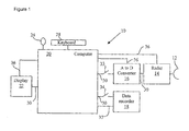
- a radar target detection system suitable for collecting data for use by the invention, and also for implementation of the invention. It is indicated generally by a data acquisition system 10, a SAR image formation system 100 and a CCD image formation system 300 respectively. Each of the sub-systems 10, 100 and 300 are explained hence forth.
- the system 10 referred to in Figure 1 is the Integrated Airborne Targeting Laboratory (IATL) radar system operating from an Andover aircraft.
- the system 10 is used in the collection of raw radar data, prior to processing according to the present invention. It comprises an antenna 12 mounted within a pod that suspends from underneath the aircraft fuselage, a radar 14, an analogue-to-digital (A to D) converter 16, a data recorder 18, a computer 20 and a display device 22.
- the computer 20 is under operator control via a mouse 24 and a keyboard 28.
- Data passes between parts of the system 10 along data lines 30, of which those between the computer and A-to-D converter 16 and the computer 20 and data recorder 18, include respective switches 33 and 34.
- Control lines 36 provide for computer-generated control signals to pass to the radar device 14, the A-to-D converter 16 and the display device 22.
- a communication line 37 is provided for passing messages between the computer 20 and data recorder 18.
- the antenna 12 is a high gain antenna.
- the radar 14 is a coherent pulse radar. It uses the same antenna for transmitting and receiving and is therefore a monostatic system. It operates at a centre frequency of 9.46GHz and at this frequency the antenna has a beam width of 1.26° degrees in azimuth and 7.95° in elevation.
- the radar has a peak transmit power of 3500W and is able to operate at ranges from 10-100km. It is capable of operating at a maximum bandwidth of 1.44 GHz. In collecting the data used in an example embodiment described herein the operating bandwidth was set to 1.44 GHz the maximum supported by the system.
- the radar is linearly polarised with both transmit and receive polarisations set to horizontal. It operates by transmitting a series of pulses at a Pulse Repetition Frequency (PRF) of 1000 Hz. Full details of the IATL system can be found in Reference [9].
- PRF Pulse Repetition Frequency
- the radar After each pulse has been transmitted, the radar is quiescent for a short duration and then records 11279 values corresponding to radar echo from a series of 11279 concurrent range cells.
- the range cells are arranged along a radial line extending outwardly from the antenna centre.
- the first range cell is the nearest in range to the antenna and the last the furthest in range.
- the radar uses the time delay between the end of transmission of a pulse and the start of the recording of the first range cell to determine the slant range offset to the start of the first range cell.
- the antenna can pan -15 degrees to +15 degrees in azimuth and from +5 degrees to -45 degrees in elevation.
- the elevation angle is set to -9.2 degrees.
- a fixed Point Of Interest (POI) on the ground is specified and the radar automatically adjusts the antenna azimuth aim point to continually point directly at the POI.
- POI Point Of Interest
- Each of the 11279 values that the radar records for each pulse that is transmitted is a complex value with a real and imaginary part.
- the analogue signal is passed through an A-to-D converter where the signal is digitised. All subsequent processing is performed on the digital data.
- the radar transmits 1000 pulses per second and receives data for 11279 range cells for each pulse.
- the A-to-D converter 16 is of a standard type and is capable of digitising both real and imaginary parts of a complex input signal.
- the data recorder 18 is a standard high-speed tape recorder, for example a Quantum LTO-3 tape recorder with 800GB of capacity on a single cartridge and backup speeds of 324GB/hr.
- the computer 20 is an Opteron computer with four 2.4 GHz AMD Opteron processors.
- the system 10 has a graphical user interface (GUI) which is displayed on the display device 22 and with which an operator may interact with the system 10 using the mouse 24 and the keyboard 28. Results generated by the system 10 are also displayed on the display device 22.
- GUI graphical user interface
- GUI displays There are two separate GUI displays; a radar data monitor that reports the progress of the platform on a map together with a range of house keeping parametric information and an image viewer where processed imagery can be presented to the operator.
- the image viewer GUI has a number of additional user functionality such as map overlays and tools for navigating around the image and manipulating multiple images.
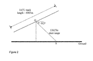
- the IATL flies a track 6903m standing-off at a range that gives a slant range of 12627m from the centre of the IATL track (Point O) to the chosen POI on the ground (Point S).
- the track altitude is chosen to give a grazing angle of -9.2° from track centre Point O to the POI S.
- the IATL is flown in a straight line along the track at a constant speed of 83 m/s.
- the antenna 12 azimuth is trained on the POI S. As the IATL platform progresses along the track the azimuth angle of the antenna 12 is automatically steered by the radar to keep the antenna aim point continuously pointing at the POI. This form of data acquisition is termed spotlight mode imaging.
- IATL aligns along the designated imaging track.
- the antenna 12 is pointed at the POI S.
- the initial azimuth squint angle of the antenna 12 is about +15 degrees.
- the radar device 14 is automatically switched on by the computer 20 when IATL reaches the designated point along the track for start of imaging.
- the switch 33 is closed and raw radar data is recorded onto the memory storage in computer 20.
- the IATL platform flies along the designated 6903m long track at a nominal speed of 83 m/s.
- the antenna 12 azimuth angle is continually adjusted by control signal from the computer 20.
- the antenna 12 squint angle falls to 0 degrees.
- the antenna 12 has negative squint angles.
- the switch 33 is opened and the radar 14 is shut down.
- the operator enters a command using the keyboard 28 for the computer 20 to close the switch 34 and store a copy of the data from the computer 20 memory on to the recorder device media.
- the switch 34 is opened.
- the operator makes a note of the file names of the data stored on the recorder device 18 that has been automatically generated by the computer 20. This completes the data acquisition step for system 10.
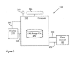
- Shown in Figure 3 is a SAR image formation system 100, used to produce base images for later processing according to the present invention. It comprises a data recorder 180, a computer 200 and a display device 220.
- the computer 200 is under operator control via a mouse 240 and a keyboard 280. Data passes between parts of the system 100 along data lines 300.
- Control lines 360 provide for computer-generated control signals to pass to the display device 220.
- a communication line 370 is provided for passing messages between the computer 200 and data recorder 180.
- the data recorder 180, the computer 200 and its peripherals 220 to 370 are identical to the devices numbered 18 through to 37 in Figure 1 .
- an operator uses keyboard 280 to set up parameters required by the system, including the latitude, longitude and altitude of a region of interest, the aircraft bearing angle, grazing angle, slant range offset along with required starting and ending azimuth squint angle of antenna 12 and number of squint angle steps.
- the squint angle is the off-boresight angle.
- Zero degree squint is the angle pointing in the direction of platform broadside.
- Positive squint is pointing toward the nose of the platform and negative squint along the tail.
- the squint angle for pointing in the direction of the platform nose is +90 degrees.
- each SAR image is of the size 3002 azimuth pixels by 8002 range pixels with the pixel spacing being 0.1 m in both azimuth and range.
- the algorithms for forming spotlight SAR base images at squinted geometry from raw radar pulses are known. References [11] and [12] are just two examples from among several open literature references describing the method for producing spotlight SAR images at arbitrary squint angles from raw radar data from a moving platform.
- the system 100 is deployed to produce SAR base images from two independent imaging passes against the same POI that were flown approximately 22 minutes apart. Data from each of the two passes is processed to form SAR base images from squint angle 6 degrees to 12 degrees.
- the description below shows the processing of 7 SAR base image files 250 produced during each pass.
- each SAR base image is taken from a viewpoint separated spatially by approximately 230 m from the last, and separated temporally by around 2.8 seconds. Thus between each image being recorded there is time for an appreciable amount of movement for ground vehicles moving at normal speeds, and thus time for significant "tracks" to be created.
- the SAR base image files from the primary (first) pass will be referred to hence forth as P 1 , P 2 , ising, P 7 .
- P 1 is the label for the SAR base image file at squint angle 12 degrees
- P 2 is the label for the SAR base image file at squint angle 11 degrees and so on.
- P 7 is the label for the SAR base image file at squint angle 6 degrees.
- the base images from the second pass will be referred to as S 1 , S 2 , ising, S 7 where the subscript x in S x corresponds to the identical squint angle as the subscript for the primary images P x .
- P 1 and S 1 are two SAR images from the primary and repeat pass respectively each formed at identical squint angles which for this embodiment is 12 degrees.
- Each of the SAR base image files 250 from both the primary and repeat pass is a 2-dimensional matrix that has 8002 rows with each row containing 3002 columns. Each row represents radar data received from a specified range position and each column represents data from specified azimuth position. Therefore, for example element (100, 12) will be the radar data derived from the 100th range cell at the 12th azimuth cell.
- the full 2-dimensional matrix is thus a SAR image that is 8002 range cell pixels by 3002 azimuth cell pixels in size.
- Each element or pixel in the 2-dimensional matrix is a complex number with a real and imaginary component.
- the pixel value represents the complex Radar Cross Section (RCS) for the corresponding location on the ground as measured by the radar.
- RCS complex Radar Cross Section
- SAR base image files 250 are stored on the computer 200.
- the data files 250 are stored as binary files with an ASCII header that contains information on the pixel spacing and the SAR image squint angle. Thus for file P 1 the header will state a squint angle of 12 degrees.
- the generation of the SAR image data files P 1 to P 7 and S 1 to S 7 completes the SAR image formation process for system 100.
- Figure 4 shows the steps involved in a first embodiment of the present invention. It shows a flow diagram illustrating the steps of routine 305 to 330 executed by the computer 200 to process the SAR image files 250 to produce the CCD base line images 350 by the process 300.
- the series comprise an image selection routine 305, a pairing with primary base image routine 310, an image alignment routine 320 and finally a coherence statistics calculation routine 330.
- the output of the process 300 is a CCD base image 350.
- the operations of 305 and 310 can be performed manually where a human selects the appropriate files or the process can be automated as a script that can pair the images based on the squint angle information contained in the header of the SAR files 250.
- Routine 320 aligns the SAR image S i with P j .
- the images S i and P j are correlated with each other which provide an estimate of the mis-alignment in both row and column.
- the image S i is then shifted in row and column by this amount to produce an aligned image SS i .
- the correlation based image alignment technique is a well established procedure in image signal processing and reference [13] is just one of many references in the open literature on this topic.
- the image, alignment is performed to within 1/10 th of a pixel which is achieved by expanding the original images each by a factor of 10 before calculating the correlation.
- the alignment is then applied to the expanded version of S i before shrinking it back by a factor of 10.
- the final image SS i would then be aligned to within a 10 th of a pixel to the image P j . It may be advantages to perform the correlation calculation on small subsections of images centred on bright points that are present in both S i and P j . Each of these sub-section correlations will produce a separate alignment offset estimate which can be averaged to produce a mean alignment off-set. The procedure for applying the shift correction to S i remains the same irrespective of whether the alignment offset has been derived using the whole image or as an average of multiple alignment estimates. A skilled person will be aware of yet other techniques for producing the align result as of routine 320.
- Routine 330 then calculates the coherence statistics for SS i and P j .
- these files are labelled C i , where i is the same value index as in SS i and therefore signifies the same squint angle as for SS i .
- C i is same size as the file SS i and for that matter P j .
- a person skilled in the matter of CCD calculations can devise modified techniques for performing the process 330.
- One particular alternative is to generate multiple SS i , each with a different alignment correction and produce different C i variants.
- the final C i output is then obtained by selecting the maximum at each pixel from among the group of C i images thus calculated.
- a single iteration of the process 300 will produce one of the base CCD image 350 that have been labelled as C i .
- the process is repeated six times to generate the CCD base images C 1 ,....,C 7 . This completes the process for the CCD base image generation of system 300.
- the advantages of generating the CCD base image sequence from just two passes and taking pairs of multi-aspect images at identical geometries is that the time lapse between each CCD image in the sequence is very short - of the order of a few seconds. This allows for rapid dynamics in the scene to be captured by a change detection process as conducted by method steps 1000 as illustrated in Figure 6 .
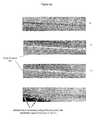
- FIG. 5a shows one embodiment of this invention with the aid of a series of image frames that illustrate the evolution of the CCD image due to ground disturbance produced by the movement of a vehicle over a grass surface.
- the top image is a SAR base image S 1 .
- S 1 SAR base image
- the second image from the top in Figure 5a is the CCD base image C 1 .
- the bottom image in Figure 5a shows a ratio image of C 1 and C 7 .
- Scene details that are present in both images appear as grey in this combined image.
- Bright scene features present only in C 1 appear dark and those present in C 7 only appear bright in the combined image.
- the vehicle trail appears grey except for the last section that appears bright white since this corresponds to new movement since the previous CCD base image, C 1 , i.e. that movement taken place between image C 1 and C 7 , the extent of which is approximately indicated by the arrows in the bottom image of Figure 5a .
- Detecting the presence of such new changes through processing of the CCD base image sequence is an important aspect of this invention that enables the detection of such dynamic events such as the movement of ground vehicles along rough surfaces.
- Figure 5B shows one embodiment of this invention with the aid of a series of image frames that illustrate the evolution of the CCD image including target shadows produced by the movement of a vehicle.
- the image on the right is a SAR base image S 1 .
- S 1 SAR base image
- the image of the vehicle is entirely invisible.
- the middle image in Figure 5B is the CCD base image C 1 .
- the vehicle happens to be moving in a part of the field that appears very bright in the CCD image.
- the shadow is recognised in the image due to a change in the intensity values in the region masked by target shadow.
- the target With reference to the image on the right in Figure 5B which is the CCD base image C 3 the target has moved further to the right in the image.
- the shadow of the target has also shifted to the right and the black box marks the new position of the CCD signal associated to the target shadow.
- a change detection result between such CCD base line images will now detect the shift in the shadow related CCD changes and hence detect, locate and estimate the velocity of the moving target without using any direct echo from the target itself. Detecting the presence of such new changes through processing of the CCD base image sequence is an important application of this invention that enables the detection of such dynamic events such as the evolution of the CCD changes due to the displacement of the shadow of the moving vehicle. As the shadow dependent CCD changes are not permanent, this means that the same patch of the image can be used for detecting separate targets. This differs from the technique that uses the ground trail as, in that approach, once a new trail is formed, the CCD change becomes permanent preventing changes from subsequent targets travelling along the same path being detected.
- the CCD changes can be observed even when the ground is not actually physically disturbed for example in the case of rigid surface.
- targets can be detected travelling not just on soft ground but also on hard surfaces where the background is sufficiently strong to enable the differences in phase due to shadow masking to be observed as such in the CCD imagery.
- the shadow CCD changes appear identical irrespective of in which pass the target was moving.
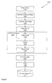
- Figure 6 shows a flow diagram illustrating the steps of routine 1001 to 1008 executed by the computer 200 to process the CCD base files 350 to perform the moving target ground trail detection process 1000.
- the outcome from these routines is displayed on the display device 220 using the data link 300.
- the series of steps comprise an image rotation routine 1001, a reference image generation routine 1003, an image ratio generation routine 1004, another image rotation routine 1005, a SAR pre-screening routine 1006, a data transformation routine 1007 and a tracking routine 1008.
- the image rotation routine 1001 rotates the image by the squint angle where the squint angle is obtained from the file ASCII header. Following this rotation the image rows and columns are aligned along the platform across-track and along-track axis. Any given pixel in the transformed images now refers to the same location on the ground. All the images are now aligned with respect to the ground.
- C 1 is rotated by an angle 12 degrees, C 2 by an angle 11 degrees and so on.
- the output of the image rotation routine 1001 is a set of 7 rotated CCD base image files. These are labelled B 1 through to B 7 .
- the reference image generation routine 1003 produces a reference image corresponding to each CCD base image from routine 1001.
- routine 1003 produces a total of 6 reference images, labelled as B 2 ref to B 7 ref .
- the reference image may be produced in any other suitable manner.
- the reference image could comprise an image formed from a plurality of rotated CCD base image using any number of statistics from mean of, maximum of pixel values etc.
- the next step is the normalisation to produce the incoherent change detection image.
- This embodiment produces the change detection image by creating a ratio, and so therefore uses the term "ratio image" to describe the change detection image.
- R i is the label referring to the ratio image for the i-th sequence image.
- the ratio image routine 1004 is applied on a total of 6 images starting from sequence number 2 and finishing with image sequence number 7.
- the generation of the ratio image (or more generally the incoherent change detection image) using the reference image is the mechanism by which the change detection for the moving trail of the ground target is realised.
- the subsequent routines 1005 to 1006 in the system 1000 of Figure 6 describe a method for automatic detection of the moving targets using the ratio images. Such automatic detection adds to the convenience of use of the invention.
- the next step following the creation of the ratio images R i is to rotate them back into the original image co-ordinate axis. This is performed using the image rotation routine 1005.
- the squint angle in the file header determines the amount by which the image is rotated.
- the difference with routine 1005 is that the rotation is performed in the opposite direction. Thus for example if the squint angle is 10 degrees then the rotation angle will be -10 degrees.
- the pre-screening routine 1006 then processes each of the D i files and generates a list of plot detections.
- the pre-screening consists of three sub-routines, initial detection (1106) (e.g. CFAR processing), clustering (1206) and discrimination (1306).
- the initial detection routine 1106 performs a bright anomaly detection. This applies a CFAR adaptive thresholding to the image D i to flag up pixels that are anomalously bright compared to the local background.
- the CFAR detection technique is familiar to those skilled in the art of radar engineering. Thus for example a CFAR algorithm for a K-distribution background is described by reference [14]. For optimum results the CFAR algorithm has to take into account the correct statistics for the background of the ratio images.
- the initial detection routine 1106 For each image D i the initial detection routine 1106 outputs a corresponding binary image of the same size.
- the binary images, labelled E i , where i 2 to 7, comprise of pixels of values zeros and ones where a one denotes a detection and a zero denotes no detection.
- Clustering routine 1206 searches through the binary image E i and groups neighbouring pixels with values one into unique clusters.
- the clustering routine 1206 is known, and more details of generic clustering algorithms of the type used by routine 1206 can be found in Reference [15].
- the clustering routine For each cluster that is identified in the binary image E i , the clustering routine outputs a list that contains a unique identification (ID) number for the cluster, the number of pixels in the cluster and the row and column indices of the pixels identified as belonging to that cluster.
- ID unique identification
- routine 1206 could output a list of the form 1 3 100,25; 100,26; 100,27
- This output list states that routine 1206 has found just one cluster which has been assigned the unique ID number "1".
- the total number of pixels in this cluster is three.
- the next three pair of numbers are the row and column indices of the three pixels belonging to cluster "1".
- the routine 1206 produces a cluster list file of this format corresponding to each binary image file E i .
- a discrimination routine 1306 is used to reject false alarms. It is designed to reject clusters that are not valid targets. For a ground target such as a vehicle trail a valid cluster is likely to have a thin narrow profile, but this could differ if, for example, the vehicle does not move very far during successive SAR image frames in a given imaging pass. Other factors, such as complex manoeuvres of the target in between SAR image frames could also cause more complex vehicle trails to exist.
- the discrimination routine 1306 uses the binary image E i along with the corresponding cluster list file L i to calculate the discriminating features associated with each cluster. Criteria are specified for valid target features.
- routine 1306 is able to select clusters either on the basis of the vehicle ground trail or their shadow footprint.
- the generation of the reference images may differ from those generated when detecting vehicle trails. As the shadows move with the targets they will appear at different places in the sequence of CDD images. To provide a better chance of detection when comparing an incoherent change detection image with a reference image, it is advantageous to temporally filter the images used to produce the reference image to reduce the influence of previous shadow images on the reference image. A shadow appearing in the incoherent change detection image will then stand out more clearly against the reference image. Such temporal filtering in producing the reference image is less important when detecting ground trails, as one is not trying to reduce the effect of previous ground trail detections.
- routine 1306 For each binary image E i , the routine 1306 reads the corresponding cluster list file L i . For each cluster listed in L i , (one per line), routine 1306 extracts a rectangular window from the image E i . The size and location of the extraction window in image E i is set such that it includes all the pixels identified as belonging to a specific cluster. However, since the cluster pixels are going to be spread somewhat randomly, a rectangle shape sub-image is likely to contain a number of zero-value pixels.
- Figure 7 illustrates a 4 by 3 sub-image for a hypothetical five pixel cluster.
- the binary sub-images corresponding to each cluster are used to estimate the cluster length, width and orientation using spatial moments.
- the spatial moment based estimation method is familiar to those skilled in the art of radar engineering and Reference [16] provides a suitable reference on this subject. From the length and width estimates, the cluster area and aspect ratio values can then be calculated.
- the discrimination process of routine 1306 involves reading the cluster list L i . For each cluster listed in L i , a rectangle sub-image from the corresponding binary image file E i is extracted and a number of spatial features are estimated and compared to a predetermined acceptance criteria. There will be one set of criteria associated with vehicle ground trail and a separate set of criteria for vehicle shadow. A more advanced acceptance criteria could combine both set of acceptance criteria within a single scheme but should make allowances that changes which meet each subset of criteria i.e. ground trail only or shadow only are accepted along with those that meet the full criteria.
- the acceptance criteria for ground trail changes may comprise a high correlation with relatively thin lines commensurate with linear movement of a target, and may also comprise high correlations with more complex shapes determined by potential movements of suspected target vehicles. Clusters for which any one of the feature values fall outside the acceptance range are reject as false alarms.
- the acceptance criteria for target shadow based CCD changes will depend upon the expected shape of target shadow footprint as determined by the length, width, area etc of the shadow region. Again clusters for which any one of the feature values fall outside the acceptance range are rejected as false alarms.
- This pre-screening detection file is an ASCII text file and is labelled P.
- the information that is recorded for each accepted cluster is the image index number "i", the squint angle corresponding to image i and the cluster centre pixel position as a row and column index number.
- the file entry for each accepted cluster will be as follows i squint_angle cluster_centre_row_no cluster_centre_column_no
- the discrimination routine 1306 processes each pair of L i and D i data files and store the output in file P using the format shown above. The process is repeated for all 6 pairs of data files and the results from each stored in the file P.
- the data file P contains the results for the pre-screening as a result of processing all the available images. It contains the complete lists of all the vehicle trails detected over the full set of images. The location for each detection refers to the centre point of the trail.
- the next step is for the data transformation routine 1007 to transform the data of file P into a format appropriate for the tracker routine 1008.
- Each line in the file P refers to a separate detection. Entries with identical image index number relate to detections reported for the same image.
- the routine 1007 reads each line and transforms the co-ordinate axis to align with the platform along-track and across track axis.
- the target row and column positions along with the image index number are recorded to a modified pre-screening file labelled as Q.
- the file Q is also an ASCII text file that contains one line entry per detection. Each entry is of the form i target_row_no target_column_no where the first entry refers to the image index number and the next two entries the position of the target.
- Routine 1007 process each target entry in file P and outputs the results to file Q.
- the file Q has the same number of entries as file P.
- the data in file Q is in the format that can be passed to the tracker routine 1008.
- the tracker routine 1008 applies a standard x-y Kalman filter to the data from file Q. This technique is familiar to those skilled in the art of tracking algorithms. A good reference on Kalman filter trackers is provided by Reference [17].
- the output from routine 1008 is stored in a tracker output file that is labelled T.
- T This is also an ASCII text file. It contains a list of targets that have produced valid tracks. Each entry recorded as a separate line in file T specifies the image index number, a unique track identifier and the target estimated row position, row velocity (m/s), column position and column velocity (m/s).
- the tracker can report a number of tracks for a given image. These will have the same image index number but different track ID numbers.
- a valid track is declared only if the target is detected in three or more consecutive images.
- the entries belonging to a specific track will have the same track id number but incrementing image index numbers. For example an entry in the file T may have the following values 6 3 145 5.6 55 1.2
- This entry means that in image 6, the target belonging to the unique track id 3 is reported at row position 145 with a velocity along the row direction of 5.6 m/s. Its column position is 55 with a velocity along the column axis of 1.2 m/s.
- the generation of the tracking result file T completes the CCD moving target detection system 1000.
- Target motion parameters estimates obtained with method 1000 can then be used to refocus the original SAR image SS i to recover an image of the target.
- the focusing procedure would be similar to that describes in reference [18] but instead of performing an exhaustive search over all possible combinations of target motion only the parameters obtained from method 1000 are applied. This will therefore result in a large saving in processing time and effort over the exhaustive search.
- the actual re-focusing process for a particular target will involve translating the target velocities specified in terms of along-track velocity (parallel to platform direction of travel) and cross-track velocity (perpendicular to platform direction of travel) into equivalent phase correction over the SAR synthetic aperture length.
- the mapping is such that the cross-track velocity component equated to a linear phase shift over the SAR synthetic aperture and the along-track velocity component equates to a quadratic phase shift over the SAR synthetic aperture.
- Target accelerations in along and cross-track direction produce higher order phase corrections.
- higher order motion components produce even higher order phase corrections across the SAR aperture.
- the target velocity components are taken into account in the phase correction term along with cross-track acceleration.
- a single expression is produced that combines the phase correction for all the motion components being considered.
- This phase correction term is transformed into the frequency domain.
- the SAR base image (of the type SS i ) is transformed in frequency along the azimuth dimension (rows).
- the frequency domain image is multiplied by the frequency correction term and the resultant is inverse frequency transformed along the azimuth dimension (row) to obtain a corrected SAR image in the original spatial domain.
- the target image in the adjusted SAR image is now correctly focused.
- the focusing process is repeated for each SAR base image SS i .
- the whole re-focusing procedure for all aligned SAR base images is repeated for each detected target.
- the target RCS or target size can be estimated from the focused SAR image and if this falls below a certain level then this can provide a mechanism for highlighting those targets that have a particularly low RCS value. Direct confirmation of the RCS of low signature targets is particularly difficult since traditional GMTI and SAR detection method will fail to detect the low RCS targets in the first instance.
- the detection performance is essentially independent of the target RCS.
- Focused images of the target can provide estimates of the target size either directly from the target image or from the shadows of the target given known imaging geometries.
- a rough estimate of the target size can be ascertained from the target axle length which can be obtained by measuring the distance between pairs of lines formed in the CCD images from tyres that are at either end of the axel of a vehicle.
- a ratio can be formed of the target RCS against target size. The ability to generate this ratio criterion will be entirely independent of the target actual RCS value.
- the focused sequence of images for a given detected target can then be deployed in any of the available multi-frame recognition schemes such as active contour delineation as detailed in reference [19] and [20] to classify the target.
- the classification scheme can utilise the focused image of the target or the shadow image or both for the purpose of recognition.
- the vehicle trail can be detected using template match lines, feature extract lines, segmentation and similar techniques.
- the method is not limited to the detection of just moving vehicles.
- the CCD base image sequence can be utilised to observe and detect any dynamic event that is producing a temporal change in the scene. Provided that the change is observed via the incoherent change detection applied to the CCD base image sequence, the location and the translation motion parameters of the dynamic event can be estimated through the method described herein.
Landscapes
- Engineering & Computer Science (AREA)
- Remote Sensing (AREA)
- Radar, Positioning & Navigation (AREA)
- Physics & Mathematics (AREA)
- Electromagnetism (AREA)
- Computer Networks & Wireless Communication (AREA)
- General Physics & Mathematics (AREA)
- Radar Systems Or Details Thereof (AREA)
- Image Processing (AREA)
Claims (15)
- Verfahren zum Bestimmen von Bewegungsparametern eines bodenbasierten Ziels durch Verarbeiten erster und zweiter zeitlicher Sequenzen von Rücksendungen von einem Synthetic Aperture-System, wobei jede Sequenz während separater Bildgebungsdurchläufe erfasst wird, wobei die Rücksendungen eine Vielzahl von Synthetic Aperture-Grundbildern einer Region umfassen, dadurch gekennzeichnet, dass es die folgenden Schritte umfasst:i) Paaren eines Bildes in der zweiten zeitlichen Sequenz mit einem entsprechenden primären Bild aus der ersten zeitlichen Sequenz, Anpassen der Bilder falls erforderlich und Bilden eines kohärenten Veränderungsdetektions-(CCD)-Bildes,
und Wiederholen für jedes Paar zum Produzieren einer Vielzahl von CCD-Grundbildern;ii) Bilden eines Referenzbildes aus einem oder mehreren der CCD-Grundbilder;iii) Bilden eines "inkohärenten Veränderungsdetektions-", ICD-Bildes durch Normalisieren des Referenzbildes mit einem entsprechend angepassten, zuvor festgelegten CCD-Grundbild aus der Sequenz;iv) Analysieren des ICD-Bildes zum Erkennen einer vom Ziel hinterlassenen Spur; undv) Erkennen eines Ziels durch Produzieren eines oder mehrerer scharfer Bilder durch Manipulieren von Phasen der zeitlichen Rücksendungen gemäß anhand der Spur eines Ziels abgeschätzten Bewegungsparametern. - Verfahren wie in Anspruch 1 beansprucht, wobei die Rücksendungen von einem Synthetic Aperture-Radarsystem kommen.
- Verfahren wie in Anspruch 1 oder Anspruch 2 beansprucht, wobei die Schritte ii) und iii) für aufeinanderfolgende CCD-Grundbilder wiederholt werden, um eine Sequenz inkohärenter Veränderungsdetektionsbilder zu bilden.
- Verfahren wie in einem der Ansprüche 1 bis 3 beansprucht, wobei das Referenzbild eines von (a) eines der CCD-Bilder oder (b) ein durch zeitliches Filtern zweier oder mehrerer der CCD-Grundbilder gebildetes Bild umfasst.
- Verfahren wie in Anspruch 1 oder Anspruch 2 beansprucht, wobei das inkohärente Veränderungsdetektionsbild ein Verhältnis zweier CCD-Grundbilder umfasst.
- Verfahren wie in einem der obigen Ansprüche beansprucht, wobei ein oder mehrere inkohärente Veränderungsdetektionsbilder auf zufälliges, thermisches Rauschen analysiert werden, das nicht mit dem Erkennen des Schattens des Ziels in den Bildern korreliert.
- Verfahren wie in einem der obigen Ansprüche beansprucht, wobei das Verfahren zum Erhalt scharfer Bilder des sich bewegenden Ziels für jede separate Zielspur, die erkannt wird, wiederholt wird.
- Verfahren wie in einem der Ansprüche 6 oder 7 beansprucht, das so angepasst ist, dass scharfe Bilder basierend auf Schatten eines sich bewegenden Ziels erhalten werden.
- Verfahren wie in einem der Ansprüche 6 bis 8 beansprucht, wobei ein Radarquerschnittswert des erkannten Ziels anhand seines scharfen Bildes abgeschätzt wird.
- Verarbeitungssystem zum Erkennen von Bewegungsparametern eines Ziels, wobei das Verarbeitungssystem Rücksendungen von einem Synthetic Aperture-System verarbeitet, einen Prozessor umfasst, der so angepasst ist, dass er Daten vom Synthetic Aperture-System empfängt, wobei die Daten Bildinformationen von zwei unabhängigen Bildgebungsdurchläufen derselben Szene umfassen, wobei die Bildinformationen eine Vielzahl von Synthetic Aperture-Bildern von jedem Durchlauf der Szene umfassen, wobei das Verarbeitungssystem einen Prozessor umfasst, der so angepasst ist, dass er die Daten in der Form von Synthetic Aperture-Bildern von den zwei unabhängigen Bildgebungsdurchläufen verarbeitet und primäre und Wiederholungsdurchlaufbilder für dieselben Geometrien paart, um ein kohärentes Veränderungsdetektions-, CCD-Bild für jedes Paar zu produzieren, dadurch eine Vielzahl von CCD-Grundbildern generiert;
dadurch gekennzeichnet, dass:der Prozessor so angepasst ist, dass er ein Referenzbild aus einem oder mehreren der CCD-Grundbilder bildet, wobei das eine oder die mehreren CCD-Grundbilder in Bezug aufeinander angemessen räumlich angepasst sind; undder Prozessor weiter so angepasst ist, dass er das Referenzbild mit einem gegebenen CCD-Grundbild normalisiert, um ein zugehöriges inkohärentes Veränderungsdetektionsbild zu bilden, wobei das gegebene CCD-Grundbild angemessen an das Referenzbild angepasst ist,der Prozessor weiter so angepasst ist, dass er ein oder mehrere inkohärente Veränderungsdetektionsbilder analysiert, um eine vom Ziel am Boden hinterlassene Spur zu erkennen, und um ein Ziel zu lokalisieren, indem durch Manipulieren von Phasen der zeitlichen Rücksendungen gemäß anhand der Spur eines Ziels abgeschätzten Bewegungsparametern ein oder mehrere scharfe Bilder produziert werden. - Verarbeitungssystem wie in Anspruch 10 beansprucht, wobei das System einen Teil eines Synthetic Aperture-Radarsystems bildet.
- Verarbeitungssystem wie in einem der Ansprüche 10 oder 11 beansprucht, wobei der Prozessor so angepasst ist, dass er eine Vielzahl von inkohärenten Veränderungsdetektionsbildern aus einer Folge von CCD-Grundbildern produziert und die Vielzahl von inkohärenten Veränderungsdetektionsbildern verarbeitet, um sich bewegende Ziele in der Szene automatisch zu erkennen.
- Verarbeitungssystem wie in einem der Ansprüche 10 bis 12 beansprucht, wobei der Prozessor so angepasst ist, dass er das / die Referenzbild(er) durch zeitliches Filtern zweier oder mehrerer der CCD-Grundbilder bildet.
- Verarbeitungssystem wie in einem der Ansprüche 10 bis 13 beansprucht, wobei der Prozessor so angepasst ist, dass er das / die inkohärente(n) Veränderungsbild(er) durch Berechnen eines Verhältnisses zweier CCD-Grundbilder bildet.
- Computerprogramm, das so angepasst ist, dass es das Verfahren wie in Anspruch 1 beansprucht auf einem Computersystem umsetzt, und weiter so angepasst ist, dass es Bilddaten produziert, die ein inkohärentes Veränderungsdetektionsbild umfassen, wenn es auf dem Computersystem läuft.
Applications Claiming Priority (3)
| Application Number | Priority Date | Filing Date | Title |
|---|---|---|---|
| GBGB0823034.4A GB0823034D0 (en) | 2008-12-18 | 2008-12-18 | System and method for processing radar imagery |
| US17418709P | 2009-04-30 | 2009-04-30 | |
| PCT/GB2009/002619 WO2010070261A1 (en) | 2008-12-18 | 2009-11-04 | System and method for processing radar imagery |
Publications (2)
| Publication Number | Publication Date |
|---|---|
| EP2370834A1 EP2370834A1 (de) | 2011-10-05 |
| EP2370834B1 true EP2370834B1 (de) | 2015-09-02 |
Family
ID=40343763
Family Applications (1)
| Application Number | Title | Priority Date | Filing Date |
|---|---|---|---|
| EP09753180.0A Active EP2370834B1 (de) | 2008-12-18 | 2009-11-04 | System und verfahren zum verarbeiten von radarbildmaterial |
Country Status (5)
| Country | Link |
|---|---|
| US (1) | US8805005B2 (de) |
| EP (1) | EP2370834B1 (de) |
| ES (1) | ES2551320T3 (de) |
| GB (1) | GB0823034D0 (de) |
| WO (1) | WO2010070261A1 (de) |
Families Citing this family (43)
| Publication number | Priority date | Publication date | Assignee | Title |
|---|---|---|---|---|
| US8072482B2 (en) * | 2006-11-09 | 2011-12-06 | Innovative Signal Anlysis | Imaging system having a rotatable image-directing device |
| US9430923B2 (en) * | 2009-11-30 | 2016-08-30 | Innovative Signal Analysis, Inc. | Moving object detection, tracking, and displaying systems |
| US8384583B2 (en) * | 2010-06-07 | 2013-02-26 | Ellegi S.R.L. | Synthetic-aperture radar system and operating method for monitoring ground and structure displacements suitable for emergency conditions |
| CN102096921B (zh) * | 2011-01-10 | 2013-02-27 | 西安电子科技大学 | 基于邻域对数比值及各向异性扩散的sar图像变化检测方法 |
| US8692704B1 (en) * | 2011-09-23 | 2014-04-08 | Sandia Corporation | Registering coherent change detection products associated with large image sets and long capture intervals |
| FR2983307B1 (fr) * | 2011-11-24 | 2014-01-31 | Thales Sa | Procede de detection coherente de changements en imagerie sar |
| US9476970B1 (en) * | 2012-03-19 | 2016-10-25 | Google Inc. | Camera based localization |
| CN103839218B (zh) * | 2012-11-22 | 2017-08-29 | 上海新跃仪表厂 | 一种二维图像数据转换一维脉冲数据方法 |
| CN103455825B (zh) * | 2013-09-08 | 2016-10-19 | 西安电子科技大学 | 基于邻域聚类核的sar图像变化检测方法 |
| CN103530635A (zh) * | 2013-09-23 | 2014-01-22 | 上海海洋大学 | 一种基于卫星微波遥感图像的海岸线提取方法 |
| JP6207370B2 (ja) * | 2013-12-10 | 2017-10-04 | 三菱電機株式会社 | 画像合成装置及び画像合成方法 |
| CN103914704B (zh) * | 2014-03-04 | 2017-02-08 | 西安电子科技大学 | 一种基于半监督SVM和MeanShift的极化SAR图像分类方法 |
| US10459061B2 (en) | 2014-05-08 | 2019-10-29 | Src, Inc. | FFT-based displaced phase center array/along-track interferometry architecture |
| GB2528089A (en) * | 2014-07-09 | 2016-01-13 | Bae Systems Plc | Method and system for surveillance using synthetic aperture radar images |
| US10139819B2 (en) | 2014-08-22 | 2018-11-27 | Innovative Signal Analysis, Inc. | Video enabled inspection using unmanned aerial vehicles |
| GB2538095B (en) * | 2015-05-07 | 2019-07-03 | Thales Holdings Uk Plc | Recognition of Objects from Shadow and Layover Effects in Synthetic Aperture Radar Images |
| CN105184814A (zh) * | 2015-07-27 | 2015-12-23 | 成都天奥信息科技有限公司 | 基于多帧雷达图像的动目标检测跟踪方法 |
| US10037477B2 (en) | 2015-08-31 | 2018-07-31 | Massachusetts Institute Of Technology | Combined intensity and coherent change detection in images |
| US10915152B2 (en) | 2016-04-26 | 2021-02-09 | Src, Inc. | Scalable high-performance embedded computing systems |
| US10732277B2 (en) * | 2016-04-29 | 2020-08-04 | The Boeing Company | Methods and systems for model based automatic target recognition in SAR data |
| JP6604908B2 (ja) * | 2016-06-10 | 2019-11-13 | キヤノン株式会社 | 画像処理装置、その制御方法、および制御プログラム |
| US10467474B1 (en) * | 2016-07-11 | 2019-11-05 | National Technology & Engineering Solutions Of Sandia, Llc | Vehicle track detection in synthetic aperture radar imagery |
| GB2553284B (en) * | 2016-08-23 | 2020-02-05 | Thales Holdings Uk Plc | Multilook coherent change detection |
| US10535127B1 (en) * | 2017-01-11 | 2020-01-14 | National Technology & Engineering Solutions Of Sandia, Llc | Apparatus, system and method for highlighting anomalous change in multi-pass synthetic aperture radar imagery |
| JP6922445B2 (ja) * | 2017-06-06 | 2021-08-18 | 日本電気株式会社 | レーダ画像処理装置とレーダ画像処理装置方法およびレーダ画像処理装置プログラム |
| US10698104B1 (en) * | 2018-03-27 | 2020-06-30 | National Technology & Engineering Solutions Of Sandia, Llc | Apparatus, system and method for highlighting activity-induced change in multi-pass synthetic aperture radar imagery |
| CN108931771A (zh) * | 2018-06-06 | 2018-12-04 | 电子科技大学 | 一种基于合成孔径雷达成像技术的目标跟踪方法 |
| DE102018123334A1 (de) * | 2018-09-21 | 2020-03-26 | Gottfried Wilhelm Leibniz Universität Hannover | Verfahren zum Ermitteln einer Lageänderung eines Objektes |
| CN109615584B (zh) * | 2018-12-17 | 2022-12-06 | 辽宁工程技术大学 | 一种基于单应性约束的sar图像序列map超分辨率重建方法 |
| EP3916428A4 (de) * | 2018-12-30 | 2022-10-19 | T - Jump Tecnologias Ltda | Radar zur kartographie und überwachung |
| CA3089990C (en) * | 2019-08-20 | 2026-06-23 | Institut National D'optique | Method and system for detection and synthetic aperture imaging of a target |
| US11592295B2 (en) * | 2019-11-26 | 2023-02-28 | Invensense, Inc. | System and method for position correction |
| CN111208479B (zh) * | 2020-01-15 | 2022-08-02 | 电子科技大学 | 一种降低深度网络检测中虚警概率的方法 |
| CN111924117B (zh) * | 2020-08-14 | 2024-04-09 | 西安应用光学研究所 | 一种光电吊舱内置光学传感器波段自主切换方法 |
| CN112147591B (zh) * | 2020-08-27 | 2024-09-03 | 清华大学 | 一种极化雷达海面舰船检测方法及装置 |
| US11753126B2 (en) * | 2021-01-12 | 2023-09-12 | Raytheon Company | Underwater vehicle inspection |
| CN112990071B (zh) * | 2021-03-31 | 2024-01-05 | 香港中文大学(深圳) | 一种输电线路异常检测方法、装置及计算机可读存储介质 |
| CN113435284B (zh) * | 2021-06-18 | 2022-06-28 | 武汉理工大学 | 基于动态过滤与多方向关注融合的灾后道路提取方法 |
| US20240201701A1 (en) * | 2021-09-24 | 2024-06-20 | Aloft Sensing, Inc. | System and method of relative navigation in a network of mobile vehicles |
| US11933883B2 (en) * | 2021-09-24 | 2024-03-19 | Aloft Sensing, Inc. | System and method for self-contained high-precision navigation |
| CN114092520B (zh) * | 2021-11-19 | 2023-12-26 | 电子科技大学长三角研究院(湖州) | 基于生成对抗网络的地面运动目标重聚焦方法及系统 |
| CN117036753B (zh) * | 2023-07-18 | 2024-06-21 | 北京观微科技有限公司 | 一种基于模板匹配和InfoGAN的SAR图像扩容方法 |
| CN118037775A (zh) * | 2024-02-02 | 2024-05-14 | 北京无线电测量研究所 | 一种基于运动模态的视频sar运动目标阴影检测方法和装置 |
Family Cites Families (5)
| Publication number | Priority date | Publication date | Assignee | Title |
|---|---|---|---|---|
| US5818383A (en) * | 1981-11-27 | 1998-10-06 | Northrop Grumman Corporation | Interferometric moving vehicle imaging apparatus and method |
| US5563601A (en) | 1985-08-16 | 1996-10-08 | Northrop Grumman Corporation. | Two-port synthetic aperature radar system for radar detection of targets |
| JP3228638B2 (ja) * | 1994-06-08 | 2001-11-12 | 松下電器産業株式会社 | 背景差分法を用いた移動体検出方法 |
| US6650273B1 (en) | 2002-05-06 | 2003-11-18 | Lockheed Martin Corporation | Change subtraction of synthetic aperture radar data |
| GB0606489D0 (en) | 2006-03-31 | 2006-05-10 | Qinetiq Ltd | System and method for processing imagery from synthetic aperture systems |
-
2008
- 2008-12-18 GB GBGB0823034.4A patent/GB0823034D0/en not_active Ceased
-
2009
- 2009-11-04 ES ES09753180.0T patent/ES2551320T3/es active Active
- 2009-11-04 US US13/139,882 patent/US8805005B2/en active Active
- 2009-11-04 EP EP09753180.0A patent/EP2370834B1/de active Active
- 2009-11-04 WO PCT/GB2009/002619 patent/WO2010070261A1/en not_active Ceased
Also Published As
| Publication number | Publication date |
|---|---|
| US8805005B2 (en) | 2014-08-12 |
| EP2370834A1 (de) | 2011-10-05 |
| US20110299733A1 (en) | 2011-12-08 |
| ES2551320T3 (es) | 2015-11-18 |
| GB0823034D0 (en) | 2009-01-28 |
| WO2010070261A1 (en) | 2010-06-24 |
Similar Documents
| Publication | Publication Date | Title |
|---|---|---|
| US8805005B2 (en) | System and method for processing radar imagery | |
| US7898457B2 (en) | System and method for processing imagery from synthetic aperture systems | |
| Wang et al. | Preliminary research of low-RCS moving target detection based on Ka-band video SAR | |
| US8339306B2 (en) | Detection system and method using gradient magnitude second moment spatial variance detection | |
| US6756935B1 (en) | Full polarization ground moving target indicator radar automatic target detection algorithm | |
| US7830300B2 (en) | Radar imaging system and method using directional gradient magnitude second moment spatial variance detection | |
| CN111812648A (zh) | 多通道合成孔径雷达rpca幅相联合目标检测方法与装置 | |
| US8212717B2 (en) | Radar imaging system and method using second moment spatial variance | |
| Henke et al. | Moving target tracking in SAR data using combined exo-and endo-clutter processing | |
| Newey et al. | Detection and imaging of moving targets with LiMIT SAR data | |
| Dudgeon et al. | Use of persistent scatterers for model-based recognition | |
| Iqbal et al. | Coastline extraction from SAR data using Doppler centroid images | |
| Pastina et al. | Exploitation of the COSMO-SkyMed SAR system for GMTI applications | |
| Budillon et al. | Contextual information based SAR tomography of urban areas | |
| Hoffmann et al. | Filter-based segmentation of automotive SAR images | |
| Xu et al. | A novel PS selection and registration algorithm based on generalization area for GNSS-based InBSAR | |
| Dogan et al. | Double dual focusing for range ambiguity suppression-experimental results | |
| Mertens et al. | Ground target tracking with experimental data of the PAMIR system | |
| Banda et al. | Polarimetric time-frequency analysis of vessels in Spotlight SAR images | |
| Smessaert et al. | Improvement prospects of DTM reconstruction from P-band SAR tomography over tropical dense forests | |
| Hong et al. | Single-channel UWB SAR ground moving targets detection method using change detection based on single-pass sub-aperture images | |
| Magnard et al. | Processing of MEMPHIS millimeter wave multi-baseline InSAR data | |
| DiPietro et al. | SAR imaging and detection of moving targets | |
| Xu et al. | A PS points selection algorithm based on edge detection for GNSS-based InSAR system | |
| Budillon et al. | An improved SAR tomographic technique using contextual information |
Legal Events
| Date | Code | Title | Description |
|---|---|---|---|
| PUAI | Public reference made under article 153(3) epc to a published international application that has entered the european phase |
Free format text: ORIGINAL CODE: 0009012 |
|
| 17P | Request for examination filed |
Effective date: 20110628 |
|
| AK | Designated contracting states |
Kind code of ref document: A1 Designated state(s): AT BE BG CH CY CZ DE DK EE ES FI FR GB GR HR HU IE IS IT LI LT LU LV MC MK MT NL NO PL PT RO SE SI SK SM TR |
|
| DAX | Request for extension of the european patent (deleted) | ||
| GRAP | Despatch of communication of intention to grant a patent |
Free format text: ORIGINAL CODE: EPIDOSNIGR1 |
|
| INTG | Intention to grant announced |
Effective date: 20150528 |
|
| RIN1 | Information on inventor provided before grant (corrected) |
Inventor name: JAHANGIR, MOHAMMED Inventor name: KEALEY, PAUL, GRAHAM Inventor name: MOATE, CHRISTOPHER, PAUL Inventor name: HILL, ROBERT, DAVID |
|
| GRAS | Grant fee paid |
Free format text: ORIGINAL CODE: EPIDOSNIGR3 |
|
| GRAA | (expected) grant |
Free format text: ORIGINAL CODE: 0009210 |
|
| AK | Designated contracting states |
Kind code of ref document: B1 Designated state(s): AT BE BG CH CY CZ DE DK EE ES FI FR GB GR HR HU IE IS IT LI LT LU LV MC MK MT NL NO PL PT RO SE SI SK SM TR |
|
| REG | Reference to a national code |
Ref country code: GB Ref legal event code: FG4D |
|
| REG | Reference to a national code |
Ref country code: AT Ref legal event code: REF Ref document number: 746971 Country of ref document: AT Kind code of ref document: T Effective date: 20150915 Ref country code: CH Ref legal event code: EP |
|
| REG | Reference to a national code |
Ref country code: IE Ref legal event code: FG4D |
|
| REG | Reference to a national code |
Ref country code: DE Ref legal event code: R096 Ref document number: 602009033358 Country of ref document: DE |
|
| REG | Reference to a national code |
Ref country code: SE Ref legal event code: TRGR |
|
| REG | Reference to a national code |
Ref country code: ES Ref legal event code: FG2A Ref document number: 2551320 Country of ref document: ES Kind code of ref document: T3 Effective date: 20151118 |
|
| REG | Reference to a national code |
Ref country code: FR Ref legal event code: PLFP Year of fee payment: 7 |
|
| REG | Reference to a national code |
Ref country code: AT Ref legal event code: MK05 Ref document number: 746971 Country of ref document: AT Kind code of ref document: T Effective date: 20150902 |
|
| PG25 | Lapsed in a contracting state [announced via postgrant information from national office to epo] |
Ref country code: FI Free format text: LAPSE BECAUSE OF FAILURE TO SUBMIT A TRANSLATION OF THE DESCRIPTION OR TO PAY THE FEE WITHIN THE PRESCRIBED TIME-LIMIT Effective date: 20150902 Ref country code: LT Free format text: LAPSE BECAUSE OF FAILURE TO SUBMIT A TRANSLATION OF THE DESCRIPTION OR TO PAY THE FEE WITHIN THE PRESCRIBED TIME-LIMIT Effective date: 20150902 Ref country code: NO Free format text: LAPSE BECAUSE OF FAILURE TO SUBMIT A TRANSLATION OF THE DESCRIPTION OR TO PAY THE FEE WITHIN THE PRESCRIBED TIME-LIMIT Effective date: 20151202 Ref country code: LV Free format text: LAPSE BECAUSE OF FAILURE TO SUBMIT A TRANSLATION OF THE DESCRIPTION OR TO PAY THE FEE WITHIN THE PRESCRIBED TIME-LIMIT Effective date: 20150902 Ref country code: GR Free format text: LAPSE BECAUSE OF FAILURE TO SUBMIT A TRANSLATION OF THE DESCRIPTION OR TO PAY THE FEE WITHIN THE PRESCRIBED TIME-LIMIT Effective date: 20151203 |
|
| REG | Reference to a national code |
Ref country code: LT Ref legal event code: MG4D Ref country code: NL Ref legal event code: MP Effective date: 20150902 |
|
| PG25 | Lapsed in a contracting state [announced via postgrant information from national office to epo] |
Ref country code: PL Free format text: LAPSE BECAUSE OF FAILURE TO SUBMIT A TRANSLATION OF THE DESCRIPTION OR TO PAY THE FEE WITHIN THE PRESCRIBED TIME-LIMIT Effective date: 20150902 Ref country code: AT Free format text: LAPSE BECAUSE OF FAILURE TO SUBMIT A TRANSLATION OF THE DESCRIPTION OR TO PAY THE FEE WITHIN THE PRESCRIBED TIME-LIMIT Effective date: 20150902 |
|
| PG25 | Lapsed in a contracting state [announced via postgrant information from national office to epo] |
Ref country code: SK Free format text: LAPSE BECAUSE OF FAILURE TO SUBMIT A TRANSLATION OF THE DESCRIPTION OR TO PAY THE FEE WITHIN THE PRESCRIBED TIME-LIMIT Effective date: 20150902 Ref country code: NL Free format text: LAPSE BECAUSE OF FAILURE TO SUBMIT A TRANSLATION OF THE DESCRIPTION OR TO PAY THE FEE WITHIN THE PRESCRIBED TIME-LIMIT Effective date: 20150902 Ref country code: IS Free format text: LAPSE BECAUSE OF FAILURE TO SUBMIT A TRANSLATION OF THE DESCRIPTION OR TO PAY THE FEE WITHIN THE PRESCRIBED TIME-LIMIT Effective date: 20160102 Ref country code: CZ Free format text: LAPSE BECAUSE OF FAILURE TO SUBMIT A TRANSLATION OF THE DESCRIPTION OR TO PAY THE FEE WITHIN THE PRESCRIBED TIME-LIMIT Effective date: 20150902 Ref country code: EE Free format text: LAPSE BECAUSE OF FAILURE TO SUBMIT A TRANSLATION OF THE DESCRIPTION OR TO PAY THE FEE WITHIN THE PRESCRIBED TIME-LIMIT Effective date: 20150902 |
|
| REG | Reference to a national code |
Ref country code: DE Ref legal event code: R082 Ref document number: 602009033358 Country of ref document: DE Representative=s name: HERNANDEZ, YORCK, DIPL.-ING., DE |
|
| PG25 | Lapsed in a contracting state [announced via postgrant information from national office to epo] |
Ref country code: RO Free format text: LAPSE BECAUSE OF FAILURE TO SUBMIT A TRANSLATION OF THE DESCRIPTION OR TO PAY THE FEE WITHIN THE PRESCRIBED TIME-LIMIT Effective date: 20150902 Ref country code: PT Free format text: LAPSE BECAUSE OF FAILURE TO SUBMIT A TRANSLATION OF THE DESCRIPTION OR TO PAY THE FEE WITHIN THE PRESCRIBED TIME-LIMIT Effective date: 20160104 |
|
| REG | Reference to a national code |
Ref country code: DE Ref legal event code: R097 Ref document number: 602009033358 Country of ref document: DE |
|
| PG25 | Lapsed in a contracting state [announced via postgrant information from national office to epo] |
Ref country code: LU Free format text: LAPSE BECAUSE OF FAILURE TO SUBMIT A TRANSLATION OF THE DESCRIPTION OR TO PAY THE FEE WITHIN THE PRESCRIBED TIME-LIMIT Effective date: 20151104 Ref country code: MC Free format text: LAPSE BECAUSE OF FAILURE TO SUBMIT A TRANSLATION OF THE DESCRIPTION OR TO PAY THE FEE WITHIN THE PRESCRIBED TIME-LIMIT Effective date: 20150902 |
|
| REG | Reference to a national code |
Ref country code: CH Ref legal event code: PL |
|
| PLBE | No opposition filed within time limit |
Free format text: ORIGINAL CODE: 0009261 |
|
| STAA | Information on the status of an ep patent application or granted ep patent |
Free format text: STATUS: NO OPPOSITION FILED WITHIN TIME LIMIT |
|
| PG25 | Lapsed in a contracting state [announced via postgrant information from national office to epo] |
Ref country code: LI Free format text: LAPSE BECAUSE OF NON-PAYMENT OF DUE FEES Effective date: 20151130 Ref country code: CH Free format text: LAPSE BECAUSE OF NON-PAYMENT OF DUE FEES Effective date: 20151130 |
|
| 26N | No opposition filed |
Effective date: 20160603 |
|
| REG | Reference to a national code |
Ref country code: IE Ref legal event code: MM4A |
|
| PG25 | Lapsed in a contracting state [announced via postgrant information from national office to epo] |
Ref country code: DK Free format text: LAPSE BECAUSE OF FAILURE TO SUBMIT A TRANSLATION OF THE DESCRIPTION OR TO PAY THE FEE WITHIN THE PRESCRIBED TIME-LIMIT Effective date: 20150902 Ref country code: SI Free format text: LAPSE BECAUSE OF FAILURE TO SUBMIT A TRANSLATION OF THE DESCRIPTION OR TO PAY THE FEE WITHIN THE PRESCRIBED TIME-LIMIT Effective date: 20150902 |
|
| PG25 | Lapsed in a contracting state [announced via postgrant information from national office to epo] |
Ref country code: IE Free format text: LAPSE BECAUSE OF NON-PAYMENT OF DUE FEES Effective date: 20151104 |
|
| REG | Reference to a national code |
Ref country code: FR Ref legal event code: PLFP Year of fee payment: 8 |
|
| PG25 | Lapsed in a contracting state [announced via postgrant information from national office to epo] |
Ref country code: BE Free format text: LAPSE BECAUSE OF FAILURE TO SUBMIT A TRANSLATION OF THE DESCRIPTION OR TO PAY THE FEE WITHIN THE PRESCRIBED TIME-LIMIT Effective date: 20150902 |
|
| PG25 | Lapsed in a contracting state [announced via postgrant information from national office to epo] |
Ref country code: BG Free format text: LAPSE BECAUSE OF FAILURE TO SUBMIT A TRANSLATION OF THE DESCRIPTION OR TO PAY THE FEE WITHIN THE PRESCRIBED TIME-LIMIT Effective date: 20150902 Ref country code: SM Free format text: LAPSE BECAUSE OF FAILURE TO SUBMIT A TRANSLATION OF THE DESCRIPTION OR TO PAY THE FEE WITHIN THE PRESCRIBED TIME-LIMIT Effective date: 20150902 Ref country code: HU Free format text: LAPSE BECAUSE OF FAILURE TO SUBMIT A TRANSLATION OF THE DESCRIPTION OR TO PAY THE FEE WITHIN THE PRESCRIBED TIME-LIMIT; INVALID AB INITIO Effective date: 20091104 |
|
| PG25 | Lapsed in a contracting state [announced via postgrant information from national office to epo] |
Ref country code: CY Free format text: LAPSE BECAUSE OF FAILURE TO SUBMIT A TRANSLATION OF THE DESCRIPTION OR TO PAY THE FEE WITHIN THE PRESCRIBED TIME-LIMIT Effective date: 20150902 |
|
| PG25 | Lapsed in a contracting state [announced via postgrant information from national office to epo] |
Ref country code: HR Free format text: LAPSE BECAUSE OF FAILURE TO SUBMIT A TRANSLATION OF THE DESCRIPTION OR TO PAY THE FEE WITHIN THE PRESCRIBED TIME-LIMIT Effective date: 20150902 |
|
| PG25 | Lapsed in a contracting state [announced via postgrant information from national office to epo] |
Ref country code: TR Free format text: LAPSE BECAUSE OF FAILURE TO SUBMIT A TRANSLATION OF THE DESCRIPTION OR TO PAY THE FEE WITHIN THE PRESCRIBED TIME-LIMIT Effective date: 20150902 Ref country code: MT Free format text: LAPSE BECAUSE OF FAILURE TO SUBMIT A TRANSLATION OF THE DESCRIPTION OR TO PAY THE FEE WITHIN THE PRESCRIBED TIME-LIMIT Effective date: 20150902 |
|
| REG | Reference to a national code |
Ref country code: FR Ref legal event code: PLFP Year of fee payment: 9 |
|
| PG25 | Lapsed in a contracting state [announced via postgrant information from national office to epo] |
Ref country code: MK Free format text: LAPSE BECAUSE OF FAILURE TO SUBMIT A TRANSLATION OF THE DESCRIPTION OR TO PAY THE FEE WITHIN THE PRESCRIBED TIME-LIMIT Effective date: 20150902 |
|
| P01 | Opt-out of the competence of the unified patent court (upc) registered |
Effective date: 20230401 |
|
| PGFP | Annual fee paid to national office [announced via postgrant information from national office to epo] |
Ref country code: DE Payment date: 20251128 Year of fee payment: 17 |
|
| PGFP | Annual fee paid to national office [announced via postgrant information from national office to epo] |
Ref country code: GB Payment date: 20251127 Year of fee payment: 17 |
|
| PGFP | Annual fee paid to national office [announced via postgrant information from national office to epo] |
Ref country code: IT Payment date: 20251119 Year of fee payment: 17 |
|
| PGFP | Annual fee paid to national office [announced via postgrant information from national office to epo] |
Ref country code: FR Payment date: 20251125 Year of fee payment: 17 |
|
| PGFP | Annual fee paid to national office [announced via postgrant information from national office to epo] |
Ref country code: SE Payment date: 20251127 Year of fee payment: 17 |
|
| PGFP | Annual fee paid to national office [announced via postgrant information from national office to epo] |
Ref country code: ES Payment date: 20251201 Year of fee payment: 17 |