EP2370127B1 - Apparatus and methods for fluid pressurizing units of injection systems - Google Patents
Apparatus and methods for fluid pressurizing units of injection systems Download PDFInfo
- Publication number
- EP2370127B1 EP2370127B1 EP09764363.9A EP09764363A EP2370127B1 EP 2370127 B1 EP2370127 B1 EP 2370127B1 EP 09764363 A EP09764363 A EP 09764363A EP 2370127 B1 EP2370127 B1 EP 2370127B1
- Authority
- EP
- European Patent Office
- Prior art keywords
- plunger
- syringe
- shaft
- terminal portion
- cavity
- Prior art date
- Legal status (The legal status is an assumption and is not a legal conclusion. Google has not performed a legal analysis and makes no representation as to the accuracy of the status listed.)
- Active
Links
Images


Classifications
-
- A—HUMAN NECESSITIES
- A61—MEDICAL OR VETERINARY SCIENCE; HYGIENE
- A61M—DEVICES FOR INTRODUCING MEDIA INTO, OR ONTO, THE BODY; DEVICES FOR TRANSDUCING BODY MEDIA OR FOR TAKING MEDIA FROM THE BODY; DEVICES FOR PRODUCING OR ENDING SLEEP OR STUPOR
- A61M5/00—Devices for bringing media into the body in a subcutaneous, intra-vascular or intramuscular way; Accessories therefor, e.g. filling or cleaning devices, arm-rests
- A61M5/14—Infusion devices, e.g. infusing by gravity; Blood infusion; Accessories therefor
- A61M5/142—Pressure infusion, e.g. using pumps
- A61M5/145—Pressure infusion, e.g. using pumps using pressurised reservoirs, e.g. pressurised by means of pistons
- A61M5/1452—Pressure infusion, e.g. using pumps using pressurised reservoirs, e.g. pressurised by means of pistons pressurised by means of pistons
- A61M5/14546—Front-loading type injectors
-
- A—HUMAN NECESSITIES
- A61—MEDICAL OR VETERINARY SCIENCE; HYGIENE
- A61M—DEVICES FOR INTRODUCING MEDIA INTO, OR ONTO, THE BODY; DEVICES FOR TRANSDUCING BODY MEDIA OR FOR TAKING MEDIA FROM THE BODY; DEVICES FOR PRODUCING OR ENDING SLEEP OR STUPOR
- A61M5/00—Devices for bringing media into the body in a subcutaneous, intra-vascular or intramuscular way; Accessories therefor, e.g. filling or cleaning devices, arm-rests
- A61M5/178—Syringes
- A61M5/20—Automatic syringes, e.g. with automatically actuated piston rod, with automatic needle injection, filling automatically
- A61M5/2053—Media being expelled from injector by pressurised fluid or vacuum
-
- A—HUMAN NECESSITIES
- A61—MEDICAL OR VETERINARY SCIENCE; HYGIENE
- A61M—DEVICES FOR INTRODUCING MEDIA INTO, OR ONTO, THE BODY; DEVICES FOR TRANSDUCING BODY MEDIA OR FOR TAKING MEDIA FROM THE BODY; DEVICES FOR PRODUCING OR ENDING SLEEP OR STUPOR
- A61M5/00—Devices for bringing media into the body in a subcutaneous, intra-vascular or intramuscular way; Accessories therefor, e.g. filling or cleaning devices, arm-rests
- A61M5/007—Devices for bringing media into the body in a subcutaneous, intra-vascular or intramuscular way; Accessories therefor, e.g. filling or cleaning devices, arm-rests for contrast media
-
- A—HUMAN NECESSITIES
- A61—MEDICAL OR VETERINARY SCIENCE; HYGIENE
- A61L—METHODS OR APPARATUS FOR STERILISING MATERIALS OR OBJECTS IN GENERAL; DISINFECTION, STERILISATION OR DEODORISATION OF AIR; CHEMICAL ASPECTS OF BANDAGES, DRESSINGS, ABSORBENT PADS OR SURGICAL ARTICLES; MATERIALS FOR BANDAGES, DRESSINGS, ABSORBENT PADS OR SURGICAL ARTICLES
- A61L31/00—Materials for other surgical articles, e.g. stents, stent-grafts, shunts, surgical drapes, guide wires, materials for adhesion prevention, occluding devices, surgical gloves, tissue fixation devices
- A61L31/04—Macromolecular materials
- A61L31/048—Macromolecular materials obtained by reactions only involving carbon-to-carbon unsaturated bonds
-
- A—HUMAN NECESSITIES
- A61—MEDICAL OR VETERINARY SCIENCE; HYGIENE
- A61M—DEVICES FOR INTRODUCING MEDIA INTO, OR ONTO, THE BODY; DEVICES FOR TRANSDUCING BODY MEDIA OR FOR TAKING MEDIA FROM THE BODY; DEVICES FOR PRODUCING OR ENDING SLEEP OR STUPOR
- A61M5/00—Devices for bringing media into the body in a subcutaneous, intra-vascular or intramuscular way; Accessories therefor, e.g. filling or cleaning devices, arm-rests
- A61M5/14—Infusion devices, e.g. infusing by gravity; Blood infusion; Accessories therefor
- A61M5/142—Pressure infusion, e.g. using pumps
- A61M5/145—Pressure infusion, e.g. using pumps using pressurised reservoirs, e.g. pressurised by means of pistons
- A61M5/1452—Pressure infusion, e.g. using pumps using pressurised reservoirs, e.g. pressurised by means of pistons pressurised by means of pistons
- A61M5/14566—Pressure infusion, e.g. using pumps using pressurised reservoirs, e.g. pressurised by means of pistons pressurised by means of pistons with a replaceable reservoir for receiving a piston rod of the pump
-
- A—HUMAN NECESSITIES
- A61—MEDICAL OR VETERINARY SCIENCE; HYGIENE
- A61M—DEVICES FOR INTRODUCING MEDIA INTO, OR ONTO, THE BODY; DEVICES FOR TRANSDUCING BODY MEDIA OR FOR TAKING MEDIA FROM THE BODY; DEVICES FOR PRODUCING OR ENDING SLEEP OR STUPOR
- A61M5/00—Devices for bringing media into the body in a subcutaneous, intra-vascular or intramuscular way; Accessories therefor, e.g. filling or cleaning devices, arm-rests
- A61M5/14—Infusion devices, e.g. infusing by gravity; Blood infusion; Accessories therefor
- A61M5/168—Means for controlling media flow to the body or for metering media to the body, e.g. drip meters, counters ; Monitoring media flow to the body
- A61M5/16804—Flow controllers
- A61M5/16813—Flow controllers by controlling the degree of opening of the flow line
-
- A—HUMAN NECESSITIES
- A61—MEDICAL OR VETERINARY SCIENCE; HYGIENE
- A61M—DEVICES FOR INTRODUCING MEDIA INTO, OR ONTO, THE BODY; DEVICES FOR TRANSDUCING BODY MEDIA OR FOR TAKING MEDIA FROM THE BODY; DEVICES FOR PRODUCING OR ENDING SLEEP OR STUPOR
- A61M5/00—Devices for bringing media into the body in a subcutaneous, intra-vascular or intramuscular way; Accessories therefor, e.g. filling or cleaning devices, arm-rests
- A61M5/178—Syringes
- A61M5/20—Automatic syringes, e.g. with automatically actuated piston rod, with automatic needle injection, filling automatically
- A61M5/2066—Automatic syringes, e.g. with automatically actuated piston rod, with automatic needle injection, filling automatically comprising means for injection of two or more media, e.g. by mixing
-
- A—HUMAN NECESSITIES
- A61—MEDICAL OR VETERINARY SCIENCE; HYGIENE
- A61M—DEVICES FOR INTRODUCING MEDIA INTO, OR ONTO, THE BODY; DEVICES FOR TRANSDUCING BODY MEDIA OR FOR TAKING MEDIA FROM THE BODY; DEVICES FOR PRODUCING OR ENDING SLEEP OR STUPOR
- A61M5/00—Devices for bringing media into the body in a subcutaneous, intra-vascular or intramuscular way; Accessories therefor, e.g. filling or cleaning devices, arm-rests
- A61M5/178—Syringes
- A61M5/31—Details
- A61M5/315—Pistons; Piston-rods; Guiding, blocking or restricting the movement of the rod or piston; Appliances on the rod for facilitating dosing ; Dosing mechanisms
- A61M5/31511—Piston or piston-rod constructions, e.g. connection of piston with piston-rod
- A61M5/31513—Piston constructions to improve sealing or sliding
-
- A—HUMAN NECESSITIES
- A61—MEDICAL OR VETERINARY SCIENCE; HYGIENE
- A61M—DEVICES FOR INTRODUCING MEDIA INTO, OR ONTO, THE BODY; DEVICES FOR TRANSDUCING BODY MEDIA OR FOR TAKING MEDIA FROM THE BODY; DEVICES FOR PRODUCING OR ENDING SLEEP OR STUPOR
- A61M5/00—Devices for bringing media into the body in a subcutaneous, intra-vascular or intramuscular way; Accessories therefor, e.g. filling or cleaning devices, arm-rests
- A61M5/178—Syringes
- A61M5/31—Details
- A61M5/315—Pistons; Piston-rods; Guiding, blocking or restricting the movement of the rod or piston; Appliances on the rod for facilitating dosing ; Dosing mechanisms
- A61M5/31511—Piston or piston-rod constructions, e.g. connection of piston with piston-rod
- A61M5/31515—Connection of piston with piston rod
-
- A—HUMAN NECESSITIES
- A61—MEDICAL OR VETERINARY SCIENCE; HYGIENE
- A61M—DEVICES FOR INTRODUCING MEDIA INTO, OR ONTO, THE BODY; DEVICES FOR TRANSDUCING BODY MEDIA OR FOR TAKING MEDIA FROM THE BODY; DEVICES FOR PRODUCING OR ENDING SLEEP OR STUPOR
- A61M5/00—Devices for bringing media into the body in a subcutaneous, intra-vascular or intramuscular way; Accessories therefor, e.g. filling or cleaning devices, arm-rests
- A61M5/48—Devices for bringing media into the body in a subcutaneous, intra-vascular or intramuscular way; Accessories therefor, e.g. filling or cleaning devices, arm-rests having means for varying, regulating, indicating or limiting injection pressure
- A61M5/484—Regulating injection pressure
-
- A—HUMAN NECESSITIES
- A61—MEDICAL OR VETERINARY SCIENCE; HYGIENE
- A61M—DEVICES FOR INTRODUCING MEDIA INTO, OR ONTO, THE BODY; DEVICES FOR TRANSDUCING BODY MEDIA OR FOR TAKING MEDIA FROM THE BODY; DEVICES FOR PRODUCING OR ENDING SLEEP OR STUPOR
- A61M5/00—Devices for bringing media into the body in a subcutaneous, intra-vascular or intramuscular way; Accessories therefor, e.g. filling or cleaning devices, arm-rests
- A61M5/50—Devices for bringing media into the body in a subcutaneous, intra-vascular or intramuscular way; Accessories therefor, e.g. filling or cleaning devices, arm-rests having means for preventing re-use, or for indicating if defective, used, tampered with or unsterile
- A61M5/5066—Means for preventing re-use by disconnection of piston and piston-rod
-
- Y—GENERAL TAGGING OF NEW TECHNOLOGICAL DEVELOPMENTS; GENERAL TAGGING OF CROSS-SECTIONAL TECHNOLOGIES SPANNING OVER SEVERAL SECTIONS OF THE IPC; TECHNICAL SUBJECTS COVERED BY FORMER USPC CROSS-REFERENCE ART COLLECTIONS [XRACs] AND DIGESTS
- Y10—TECHNICAL SUBJECTS COVERED BY FORMER USPC
- Y10T—TECHNICAL SUBJECTS COVERED BY FORMER US CLASSIFICATION
- Y10T29/00—Metal working
- Y10T29/49—Method of mechanical manufacture
- Y10T29/49815—Disassembling
-
- Y—GENERAL TAGGING OF NEW TECHNOLOGICAL DEVELOPMENTS; GENERAL TAGGING OF CROSS-SECTIONAL TECHNOLOGIES SPANNING OVER SEVERAL SECTIONS OF THE IPC; TECHNICAL SUBJECTS COVERED BY FORMER USPC CROSS-REFERENCE ART COLLECTIONS [XRACs] AND DIGESTS
- Y10—TECHNICAL SUBJECTS COVERED BY FORMER USPC
- Y10T—TECHNICAL SUBJECTS COVERED BY FORMER US CLASSIFICATION
- Y10T29/00—Metal working
- Y10T29/49—Method of mechanical manufacture
- Y10T29/49826—Assembling or joining
Landscapes
- Health & Medical Sciences (AREA)
- Animal Behavior & Ethology (AREA)
- Vascular Medicine (AREA)
- Veterinary Medicine (AREA)
- Public Health (AREA)
- Heart & Thoracic Surgery (AREA)
- General Health & Medical Sciences (AREA)
- Life Sciences & Earth Sciences (AREA)
- Biomedical Technology (AREA)
- Hematology (AREA)
- Anesthesiology (AREA)
- Engineering & Computer Science (AREA)
- Chemical & Material Sciences (AREA)
- Chemical Kinetics & Catalysis (AREA)
- Surgery (AREA)
- Epidemiology (AREA)
- Infusion, Injection, And Reservoir Apparatuses (AREA)
Description
- The present disclosure pertains to injection systems and more particularly to apparatus and methods for fluid pressurizing units thereof.
- Fluid injection systems, which are used to inject a medical fluid into a patient, often include one or more reservoirs, to hold the medical fluid, and one or more pressurizing units, to inject the medical fluid. For example, a contrast media powered injection system may include a reservoir of contrast media coupled to a pressurizing unit, from which contrast is injected, to facilitate imaging during certain medical procedures, such as an angiographic or computed tomography (CT) procedure.
- The pressurizing units of medical fluid injection systems typically include at least one syringe and a plunger mounted therein. The plunger is moved, for example, by a motorized plunger shaft of the unit, in a first direction, to draw fluid into the syringe, from the one or more reservoirs, and then, in a second direction, to expel the fluid from the syringe and into the patient, for example, via a catheter, which is coupled to the pressurizing unit. Pressurizing units of many medical fluid injections systems typically employ syringe and plunger subassemblies that are disposable. These disposable syringe and plunger subassemblies may be packaged as a set, wherein the plunger is mounted in the syringe. Once assembled into the pressurizing unit, the syringe and plunger may have an operational life spanning multiple injections, for example, preferably up to 10 or more injections. For those pressurizing units that include a permanent plunger shaft, or ram, assembling the syringe and plunger therein includes coupling the shaft to the plunger prior to an injection; and, removing the syringe and plunger from the pressurizing unit, after one or more injections (for example, for replacement with a new syringe and plunger set), includes decoupling of the shaft from the plunger so that the syringe and plunger may be separated from the shaft.
- United States Patent Number
5,314,416 describes a syringe assembly including a plunger rod and a plunger tip which are designed to provide a low frictional resistance against the interior surface of the syringe barrel while the plunger rod is at rest but which will increase the sealing pressure between the plunger tip and the interior surface of the syringe barrel in proportion to the amount of force applied to the plunger rod. - United States Patent Number
5,947,929 describes a syringe and plunger. The plunger includes an array of circumferentially spaced-apart flexible resilient engagement members. - The scope of protection is defined by the independent claims, to which reference should now be made. Optional features are set out in the dependent claims.
- According to one aspect of the present invention, there is provided a fluid pressurizing unit for an injection system, the unit comprising: a syringe including a proximal opening and an inner surface; a plunger shaft including a terminal portion, the terminal portion including a distal terminal end; and a plunger mounted within the syringe, the plunger including a wiper sidewall, a deformable distal end wall and a cavity; the wiper sidewall of the plunger including at least one external sealing ridge and an external sealing lip for reversible sealing against the inner surface of the syringe, the wiper sidewall further including a radially expandable-contractible portion that includes an internal surface with a plurality of longitudinally extending ribs to facilitate the expandable and contractible nature of the radially expandable-contractible portion, without sacrificing a structural integrity of the wiper sidewall for sealing; and the cavity of the plunger being defined by the wiper sidewall and the deformable distal end wall and having an opening located opposite the distal end wall; wherein the terminal portion of the plunger shaft has a size and shape such that, when the terminal portion is fully inserted into the cavity, a gap exists between the distal terminal end of the terminal portion and the deformable distal end wall of the plunger; and the external sealing lip of the wiper sidewall of the plunger is located in proximity to the deformable distal end wall of the plunger, such that, when the terminal portion of the plunger shaft is fully inserted into the cavity of the plunger, a pressure within the syringe, which is above a given threshold pressure, deforms the end wall into the gap, thereby forcing the external sealing lip radially outward and into tighter sealing engagement with the inner surface of the syringe.
- According to another aspect of the present invention, there is provided an assembly method for a fluid pressurizing unit of an injection system, the method comprising: mounting a plunger within a proximal opening of a syringe, the plunger including a wiper sidewall, a deformable distal end wall and a cavity, the wiper sidewall of the plunger including an external sealing ridge, an external sealing lip for reversible sealing against an inner surface of the syringe, the cavity of the plunger being defined by the wiper sidewall and the deformable distal end wall and having an opening located opposite the distal end wall, the wiper sidewall including a radially expandable-contractible portion that includes an internal surface with a plurality of longitudinally extendible ribs to facilitate the expandable and contractible nature of the radially expandable-contractible portion, without sacrificing a structural integrity of the wiper sidewall for sealing; inserting a terminal portion of a plunger shaft, of the injection system, through an opening of the mounted plunger, and into the cavity of the mounted plunger, wherein the terminal portion of the plunger shaft has a size and shape such that, when the terminal portion of the plunger shaft is fully inserted into the cavity, a gap exists between a distal terminal end of the terminal portion and the deformable distal end wall of the plunger, the external sealing lip of the wiper sidewall of the plunger located in proximity of the deformable distal end wall of the plunger, such that, when the terminal portion of the plunger shaft is fully inserted into the cavity of the plunger, and when a pressure within the syringe, which is above a given threshold pressure, deforms the end wall into the gap, the external sealing lip is thereby forced radially outward and into tighter sealing engagement with the inner surface of the syringe; and advancing the inserted terminal portion of the plunger shaft within the syringe.
- A fluid pressurizing unit, for an injection system, that includes a syringe and a plunger mounted therein, wherein the plunger may be operably engaged with a plunger shaft of the unit, yet removable therefrom, is also disclosed herein. Also disclosed are configurations of a syringe and plunger subassembly, for the fluid pressurizing unit, and configurations of an individual plunger suited for incorporation in the fluid pressurizing unit.
- A plunger including a wiper sidewall, which has a radially expandable-contractible portion, extending in proximity to a proximal end of the plunger, and a mating feature, which is formed in the expandable contractible portion and projects into a cavity of the plunger, which cavity is surrounded by the wiper sidewall and has an opening at the proximal end of the plunger is disclosed. When the plunger is initially mounted within the syringe, such that the expandable-contractible portion is located within a first length of the syringe, the expandable-contractible portion is expanded, so that the mating feature of the plunger is not operably engaged with an engaging feature of the plunger shaft, which is approximately aligned therewith. According to some disclosed methods, a terminal portion of the plunger shaft is initially inserted into the cavity, when the plunger is located within the first length of the syringe, at which point the engaging feature of the shaft may be approximately aligned with the mating feature of the plunger. When the plunger shaft is subsequently advanced, to move the plunger into a second length of the syringe, wherein an inner diameter of the syringe is smaller than that of the first length, the expandable-contractible portion is contracted so that the mating feature of the plunger is operably engaged with the engaging feature of the plunger shaft.
- The wiper sidewall of some of the disclosed plungers includes an external sealing lip located in proximity to a distal end of the plunger, and the plunger further includes a deformable distal end wall. The wiper sidewall and the deformable distal end wall define the cavity of the plunger, and the terminal portion of the plunger shaft is of a size and shape so that an a gap exists between a terminal end of the terminal portion and the deformable distal end wall of the plunger, when the shaft is fully inserted into the cavity thereof. The wiper sidewall may, or may not, include the deformable portion, as described above.
- Some additional methods of the present disclosure include those directed toward disabling the syringe and plunger subassembly, for removal of the subassembly from the pressurizing unit. According to these methods, the plunger disengages from the plunger shaft of the unit, as the plunger shaft is retracted from a first position, within the syringe, to a second position, within the syringe, and, then, the plunger is allowed to be drawn back toward the first position, prior to removing the subassembly from the pressurizing unit.
- The following drawings are illustrative of particular methods and embodiments of the present disclosure and, therefore, do not limit the scope of the invention. The drawings are not to scale (unless so stated) and are intended for use in conjunction with the explanations in the following detailed description. Methods and embodiments will hereinafter be described in conjunction with the appended drawings, wherein like numerals denote like elements.
-
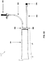
Figure 1 is a perspective view of a fluid injection system, which may incorporate embodiments of the present invention. -
Figure 2 is a perspective view of an alternative fluid injection system, which may also incorporate embodiments of the present invention. -
Figure 3A is a plan view of a subassembly for a fluid pressurizing unit, according to some embodiments of the present invention. -
Figure 3B is a perspective view of a portion of the subassembly, shown inFigure 3A , according to some embodiments. -
Figure 3C is a perspective view of a plunger, separated from the subassembly ofFigures 3A-B , according to some embodiments. -
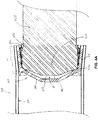
Figure 4A is a cross-section view of a portion of a fluid pressurizing unit, in a first condition, according to some embodiments. -
Figure 4B is a cross-section view of the portion of the unit, shown inFigure 4A , in a second condition, according to some embodiments. -
Figure 5 is an enlarged detail view of a portion of a plunger shaft, according to some embodiments. -
Figures 6A-C are schematics outlining some methods of the present invention. - The following detailed description is exemplary in nature and is not intended to limit applicability, or configuration of the invention in any way. Rather, the following description provides practical illustrations for implementing exemplary methods and embodiments. Examples of constructions, materials and dimensions are provided for selected elements, and all other elements employ that which is known to those of skill in the field of the invention. Those skilled in the art will recognize that many of the examples provided have suitable alternatives that can be utilized.
-
Figure 1 is a perspective view of afluid injection system 100, which may incorporate embodiments of the present invention.Figure 1 illustratessystem 100 including, a fluid pressurizingunit 130 mounted in asleeve 108, that extends from aninjector head 104 ofsystem 100, and afirst fluid reservoir 132.Reservoir 132 is shown hanging from aholder 110 and being coupled to pressurizingunit 130, via aninput tubing line 308, in order to supply fluid, for example, a contrast agent, tounit 130.Fluid pressurizing unit 130 is shown including asyringe 301, in which aplunger shaft 420 extends, and aplunger 320, which is mounted insyringe 301 and coupled to aplunger shaft 420. - According to the illustrated embodiment,
shaft 420 is coupled to a motor assembly, which is contained ininjector head 104 and which actuatesshaft 420 to driveplunger 320 in reciprocating directions withinsyringe 130.Injector head 104 may include a programmable controller to drive the motor assembly. The controller preferably includes a digital computer, which may be programmed, for example, via acontrol panel 102 ofsystem 100. The controller may further include a motor drive circuit, amplifier, tachometer, potentiometer, rectifier, pressure sensing load cell and A/D converter, for example, as described in column 10, line 45 - column 11, line 2 of commonly-assignedU.S. Patent 6,752,789 . Whenshaft 420 is actuated to moveplunger 320 proximally, towardinjector head 104, in a suction stroke, fluid, fromreservoir 132, is drawn intosyringe 301, viainput line 308, and, whenshaft 420 moves plunger 320 distally, in a compression stroke, the fluid is expelled out fromsyringe 301, through anoutput tubing line 304.Figure 1 further illustratesoutput tubing line 304 coupled to atubing line 122, which is mounted on amodule 112 ofsystem 100;tubing line 122 may be connected to a patient line, via aconnector 120, so that the fluid, which is expelled fromsyringe 301, is injected into a patient, for example, to facilitate imaging. - With further reference to
Figure 1 ,system 100 includes asecond fluid reservoir 138, which hangs from ahook 137 and from which fluid, for example, a diluent, such as saline, is drawn by aperistaltic pump 106, through atubing line 128;pump 106 is shown mounted oninjector head 104.System 100 further includes amanifold sensor 114 and amanifold valve 124, for controlling the flow of fluids intotubing line 122, either fromtubing line 128, or from pressurizingunit 130, viatubing line 304.Manifold valve 124 may comprise a spring-biased spool valve, or another type of valve, for example, a check valve. Manifoldsensor 114 can detect the position ofmanifold valve 124 and report this position toinjector head 104. - A
pressure transducer 126 is shown coupled totubing 128; whentubing 122 is connected to a patient line, that extends within a patient,pressure transducer 126 is capable of functioning as a hemodynamic monitor for the patient.Pressure transducer 126 converts detected pressures into electrical signals that may be monitored or otherwise used bysystem 100 or another monitoring device. Anair bubble detector 116 is shown coupled totubing line 122.Detector 116 is capable of generating an alarm signal, upon detection of a measurable, or otherwise significant, amount of air withintubing line 122. In addition,device 100 may automatically pause, or terminate, a fluid injection procedure, whendetector 116 detects air in the tubing. - An operator of
system 100, such as a clinician, may usecontrol panel 102 ofsystem 100 to set up various parameters and/or protocols to be used for a given injection procedure. The operator may interact withcontrol panel 102, for example, via a touch-screen panel, to enter injection parameters for flow rate, maximum injection volume, maximum injection pressure, rise time, or other parameters.Control panel 102 may further display operating parameters ofsystem 100 to the operator, and/or warning or alarm messages, for example, indicating that air has been detected byair bubble detector 116. -
Figure 1 also shows a hand-control device 136 coupled to controlpanel 102, via aconnector 134, which may be connected to, or disconnected from,control panel 102. An operator may manipulate hand-control device 136 to control injection of fluid fromsystem 100. For example, the operator may use hand-control device 136 as a variable-rate control device to variably control the rate of flow of fluid from system 100 (e.g., flow of fluid out of pressurizing unit 130). Hand-control device 136 may comprise an electrical device or a pneumatic device. - Because
system 100 may deliver many injections over a number of patient procedures, injection fluids may need to be continuously replaced.Injector head 104 may automatically replenish fluid tosyringe 301, for example, based upon monitoring of injection volumes therefrom and comparing to an initial, input, volume; or the operator ofsystem 100 may need to manually initiate a fluid replenishment procedure, upon detection that a fluid volume withinsyringe 301 has been depleted to a critical volume. It should be noted thatinjector head 104 may automatically replenish fluid tosyringe 301 based upon operational state information, other than injection volumes. For example, ifinjector head 104 determines thatsystem 100 is currently delivering fluid frompump 106, but not fromsyringe 301, and thatsyringe 301 is not filled to capacity,injector head 104 may cause the motor assembly to actuateplunger shaft 420 in order to draw additional fluid intosyringe 301, viainput line 308. - Turning now to
Figure 2 , an alternativefluid injection system 200 is shown in perspective view. Likesystem 100,system 200 may incorporate embodiments of the present invention.Figure 2 illustratessystem 200 including acontrol panel 212, which is mounted on aninjector head 201 ofsystem 200, and first andsecond sleeves injector head 201 and a corresponding one of first and secondfront end assemblies system 200.Figure 2 further illustratessystem 200 including first andsecond reservoir holders holders corresponding sleeve - Each fluid pressurizing unit of
system 200 may be very similar tounit 130 ofsystem 100 and include a syringe, which is mounted in one ofsleeves injector head 201, into the syringe, and is coupled to the plunger. Furthermore, likesystem 100, a motor assembly may be coupled each of the plunger shafts, to actuate each shaft, independently, in order to drive the corresponding plunger in reciprocating directions, for alternating suction and compression strokes. The motor assemblies are contained withininjector head 201 and may be controlled and monitored by one or more processors of a programmable controller, also included inhead 201. It should be understood that first and secondfront end assemblies system 200, contain input and output tubing lines for each pressurizing unit, wherein each input tubing line supplies fluid from the corresponding reservoir to the corresponding syringe, and each output tubing line carries fluid expelled from the corresponding syringe to a patient line, via a manifold valve.Figure 2 illustrates aguide rod 220, which facilitates connection of the patient line tosystem 200. One of the pressurizing units ofsystem 200 may expel a contrast agent for injection into the patient, via the connected patient line, and the other pressurizing unit, a diluent, such as saline. Valves and sensors, similar to those described above forsystem 100, may be incorporated into the tubing lines ofsystem 200, which are contained withinfront end assemblies system 200. -
Figure 3A is a plan view of asubassembly 350 for a fluid pressurizing unit, such as forunit 130, shown inFigure 1 , according to some embodiments of the present invention. It should be noted thatsubassembly 350 may also be employed by one or both of the pressurizing units ofsystem 200.Figure 3A illustrates subassembly 350 includingsyringe 301,input tubing line 308 andoutput tubing line 304.Figure 3A further illustratessyringe 301 including a firstdistal port 300, to whichinput tubing line 308 is coupled, a seconddistal port 302, to whichoutput tubing line 304 is coupled, and aproximal opening 31. With reference toFigure 3B , which is a perspective view looking intoproximal opening 31 ofsyringe 301,plunger 320 may be seen mounted withinproximal opening 31, such that anopening 312 into acavity 321 ofplunger 320 faces proximally, for coupling with plunger shaft 420 (Figure 1 ), whensubassembly 350 is assembled intounit 130, for example, as is illustrated in the section view ofFigure 4A . Subassembly 350 may be provided as a disposable subassembly, packaged as a set, which is replaced with a new set after a given number of injections. -
Figure 3C is a perspective view ofplunger 320, separated fromsubassembly 350, according to some embodiments.Figure 3C illustratesplunger 320 including an optionaldistal end wall 340 and awiper sidewall 330, which extends between aproximal end 331 and adistal end 332 ofplunger 320, for sealing with an inner surface 311 (Figures 4A-B ) ofsyringe 301, during suction and compression strokes ofplunger 320, for example, as driven byshaft 420. According to the illustrated embodiment, in order to facilitate the sealing withinner surface 311,wiper sidewall 330 includes a plurality of external sealingridges 335 and anexternal sealing lip 337, which will be described in greater detail, below. -
Figure 3C further illustrateswiper sidewall 330 extending proximally, fromend wall 340 to opening 312 ofcavity 321, and including a radially expandable-contractible portion 33, which surroundsopening 312.Figures 3B-C illustrate a plurality of longitudinally extendingribs 333 being formed in an inner surface ofwiper sidewall 330, extending distally fromproximal end 331 ofplunger 320, and being spaced apart from one another about a circumference ofcavity 321. According to the illustrated embodiment,ribs 333 facilitate the expandable and contractible nature of radially expandable-contractible portion 33 ofwiper sidewall 330, without sacrificing a structural integrity thereof for sealing.Figures 3B-C further illustrate a plurality oftabs 332, each of which are formed on a number ofribs 333, in proximity toproximal end 331 ofplunger 320, and project intocavity 321, as a mating feature for operably engaging with an engaging feature ofplunger shaft 420. - According to some preferred embodiments,
plunger 320 is a single, injection molded component, such that all of the above-described features, which are shown inFigures 3B-C , are integrally formed.Plunger 320 is preferably formed from a relatively soft and flexible thermoplastic material, such as polyethylene or polypropylene. Thematerial forming plunger 320 may, for example, have a density of approximately 0.955 g/cm3. According to an exemplary embodiment,plunger 320 is formed, for example, molded, from a high density polyethylene (HOPE), such as Dow HOPE 25455, manufactured by Dow Chemical Company, Midland MI. A lubricant may be applied over an external surface ofwiper sidewall 330, in order to reduce friction at the interface betweensidewall 330 andinner surface 311 ofsyringe 301, which friction could causeplunger 320 to seize withinsyringe 301, for example, via heat welding, in extreme cases. According to some preferred methods, the lubricant, for example, a silicone-based and biocompatible lubricant, is applied in anannular recess 36 ofwiper sidewall 330, prior to mountingplunger 320 withinsyringe 301, such that, whenplunger 320 is moved distally withinsyringe 301, the lubricant spreads proximally along the interface betweenwiper sidewall 330 andinner surface 311 ofsyringe 301. A dynamic viscosity of the lubricant may be between approximately 1,000 centipoise (cP) (1 Pa·s) and approximately 500,000 cP (500 Pa·s), preferably approximately 100,000 cP (100 Pa·s). - With reference back to
Figure 3A ,syringe 301 is shown including a first length L1 and a second length L2, wherein first length L1 extends fromproximal opening 31 to second length L2. Turning now toFigures 4A-B , which are cross-section views of a portion of a fluid pressurizing unit that includessubassembly 350, for example,unit 130 ofFigure 1 , a significance of lengths L1 and L2, in conjunction with expandable-contractible portion 33 ofplunger 320, will be described.Figures 4A-B show a portion ofinner surface 311 ofsyringe 301, that extends over first length L1, defining a first inner diameter ofsyringe 301, and another portion ofinner surface 311, that extends over second length L2, defining a second inner diameter ofsyringe 301, which is less than the first inner diameter.Figure 4A illustrates aterminal portion 421 ofplunger shaft 420 having been inserted intoproximal opening 31 ofsyringe 301 and into cavity 321 (Figure 3B ) ofplunger 320, which is initially mounted withinproximal opening 31.Figure 4A further illustratesshaft 420 including an engaging feature, that is formed by agroove 432 and is located at a proximal end ofterminal portion 421 ofshaft 420. According to the illustrated embodiment, the first diameter ofsyringe 301 allows expandable-contractible portion 33 ofwiper sidewall 330 to be in a relaxed, or expanded state, so thatterminal portion 421 ofplunger shaft 420, upon initial
assembly, may be freely inserted intocavity 321, without operably engaging the mating feature, for example,tabs 332, ofplunger 320 withingroove 432.Figure 4B illustrates the insertedterminal portion 421 ofplunger shaft 420 having been advanced distally, per arrow I, withinsyringe 301, untilwiper sidewall 330 ofplunger 320 is contained within second length L2. Within the smaller inner diameter of second length L2, expandable-contractible portion 33 ofwiper sidewall 330 is contracted, so thattabs 332 ofplunger 320 are now operably engaged withingroove 432 ofplunger shaft 420. -
Figures 4A-B further illustrateterminal portion 421 ofplunger shaft 420 having a size and shape to fully supportwiper sidewall 330, for sealing engagement withinner surface 311 ofsyringe 301, whenterminal portion 421 is fully inserted intocavity 321 ofplunger 320. Yet, the size and shape ofterminal portion 421 allow for a gap G to exist betweenend wall 340 ofplunger 320 and a distalterminal end 440 of fully insertedterminal portion 421. According to some preferred embodiments of the present invention,end wall 340 ofplunger 320 is deformable, so that, at a given threshold pressure, for example, directed per arrow P ofFigure 4B , during a compression stroke ofplunger shaft 420,end wall 340 deforms into gap G, for example, per the dashed lines ofFigure 4B . This deformation ofend wall 340forces sealing lip 337 radially outward and into tighter sealing engagement withinner surface 311 ofsyringe 301. During suction strokes ofplunger shaft 420, and during those compression strokes wherein pressures are lower than the threshold pressure, sealingridges 335 ofwiper sidewall 330 can maintain adequate sealing engagement withinner surface 311, to prevent fluid from leakingpast plunger 320, without relying on sealinglip 337. Although a particular number and form of sealingridges 335 are illustrated, embodiments of the invention are not so limited, and any form and/or number of suitable sealing ridges, known to those skilled in the art, may be employed byplunger 320. - According to an exemplary embodiment, the threshold pressure for deformation of
end wall 340, during a compression stroke, may range from approximately 50 psi (approximately 345 kPa) to approximately 200 psi (approximately 1380 kPa). It should be noted, however, that some deformation ofend wall 340 begins at an even lower pressure, continuing on up to the higher pressures, to provide a tighter seal as the pressure increases. For example, it was found, during testing, that a sealing lip of a plunger, for
example, similar toplunger 320, deflected, radially outward, up to 0.025 inch (approximately 0.064 cm), when not constrained by a syringe; such deflection would provide robust sealing during the compression stroke of theplunger shaft 420, in high pressure applications, of the pressurizing unit. During those compression strokes ofplunger shaft 420 that expel a contrast agent fromsyringe 301, as previously described, pressures may reach or exceed approximately 1200 psi (approximately 8270 kPa), during certain types of injection procedures, for example, angiography imaging procedures. It should be noted that the radial expansion of sealinglip 337, which is allowed by gap G, in conjunction with a deformable nature ofend wall 340, can also make up for a compression set ofwiper sidewall 330, which could occur ifplunger 320 is 'parked' for a period of time withinsyringe 301. The radial expansion of sealinglip 337 may also make up for dimensional variability, that may be encountered in manufacturing relatively large volumes of plunger and/or syringe components, and/or may result from aging and/or gamma sterilization, particularly of the plunger components. - The initial position of
plunger 320, within first length L1 of syringe, for example as shown inFigures 3B and4A , can preventplunger 320 from taking a compression set during the time, prior to use, in which subassembly 350 (Figure 3A ) remains in storage. Oncesubassembly 350 is assembled into a fluid pressurizing unit of an injection system, forexample unit 130 ofsystem 100, the operable engagement betweenplunger 320 andplunger shaft 420, for example, as illustrated inFigure 4B , enablesplunger shaft 420 to moveplunger 320 within second length L2 ofsyringe 301 over multiple reciprocating compression and suction strokes, whilewiper sidewall 330 ofplunger 320 remains in sealing engagement withinner surface 311 of syringe. - To
separate subassembly 350 fromplunger shaft 420, for example, after a certain number of injections,terminal portion 421 ofshaft 420 may be retracted back into first length L1 ofsyringe 301, where expandable-contractible portion 33 ofplunger 320 may expand, as shown inFigure 4A , so thatplunger 320 may be readily separated fromshaft 420. Separation ofplunger 320 fromshaft 420 may be desired in order to install a new subassembly, that includes a new plunger mounted in a syringe, and/or to assure thatplunger 320 is not re-used. - According to some embodiments, the engaging feature of
plunger shaft 420 may be formed to further facilitate the disengagement of the mating feature ofplunger 320 therefrom, for example, in those instances whereplunger 320 may have taken a set within second length L2 ofsyringe 301, over the course of the above-described operation, so that expandable-contractible portion 33 ofwiper sidewall 330 does not readily expand whenterminal portion 421 ofshaft 420 is moved into first length L1 of syringe. With reference toFigure 5 , which is an enlarged detail view of a portion of aplunger shaft 420, the engaging feature, or groove 432 ofshaft 420 includes a beveled edge, or a distalchamfered shoulder 503, which can act to force the mating feature, ortabs 332 ofplunger 320 radially outward, and out of engagement withgroove 432, whenplunger shaft 420 is retracted back into first length L1.Figure 5 illustratesshoulder 503 extending distally from abase 502 ofgroove 432 at an acute angle β, for example, being between approximately 30° and approximately 75°, preferably approximately 30°, with respect to a longitudinal axis ofplunger shaft 420. - Alternately, or in addition, a suction force may be created within
syringe 301, by movingshaft 420, and thus,plunger 320 towardproximal opening 31, to facilitate the disengagement ofplunger 320 fromshaft 420. This suction force may cause thedisengaged plunger 320 to be pulled withinsyringe 301, for example, toward first and seconddistal ports subassembly 350 and prevent re-use thereof, sincetabs 332 of expandable-contractible portion 33 will not allowshaft 420 to re-engage withplunger 320, whenplunger 320 is within second length L2 ofsyringe 301. Additionally, retention of thedisengaged plunger 320 withinsyringe 301 may provide for a sealing engagement thereof, withinner surface 311 ofsyringe 301, that prevents any fluid, that remains withinsyringe 301, from leaking out fromproximal opening 31, for example, assubassembly 350 is being removed from a pressurizing unit. It should be noted that gap G betweenend wall 340 ofplunger 320 and distalterminal end 440 of plunger shaft 420 (Figures 4A-B ) may further facilitate the separation ofplunger 320 fromshaft 420, particularly in combination with the aforementioned suction force. - Turning now to the schematics of
Figures 6A-C , some methods, which incorporate the aforementioned suction force for disabling and removingsubassembly 350 from a pressurizing unit, will be described. The removal is typically performed at the end of a day of system operation, but may be performed more frequently.Figures 6A-C schematically illustrate a valve 68 coupled inline withinlet tubing line 308, and avalve 64 coupled inline withoutlet tubing line 304; it should be understood that bothvalves 68, 64, for example, pinch valves, are typically closed upon completion of system operation for the day. According to preferred embodiments, the aforementioned controller, of each ofinjection systems plunger shaft 420 andvalves 64, 68 in order to carry out any of the methods described below. -
Figure 6A illustrates a method, in which bothvalves 68, 64 are closed, to isolatesyringe 301 from downstream flow paths of fluid inlet andoutlet lines syringe 301, asplunger shaft 420 movesplunger 320 proximally, per arrow C1, for example, at a speed between approximately 5 mm/sec and approximately 8 mm/sec. The vacuum, withinsyringe 301, creates a suction force, for example, between approximately 5 psi (approximately 35 kPa) and approximately 20 psi (approximately 140 kPa), to pullplunger 320 distally, per arrow C2, and out of engagement withshaft 420. According to the illustrated embodiment, the disengagement occurs asplunger 320 is moved into first length L1 ofsyringe 301, being facilitated by the enlarged inner diameter thereof, but, according to alternate embodiments, this need not be the case. For example, the suction force created by the vacuum withinsyringe 301 may be sufficient, alone, to disengageplunger 320 fromshaft 420, in whichcase syringe 301 may not include length L1 in which the inner diameter is enlarged to allow expansion ofplunger 320, as previously described; orplunger 320 may not expand in length L1, either becauseplunger 320 has taken a set during the day's operation of the system or becauseplunger 320 does not include expandable-contractible portion 33. Alternately, the engaging feature ofshaft 420 may be configured as illustrated inFigure 5 , to further facilitate disengagement ofplunger 320 fromshaft 420, via the suction force. According to some preferred methods,disengaged plunger 320 is allowed to be drawn back towarddistal ports syringe 301, for example, as shown inFigure 6B , beforesyringe 301 andplunger 320, together, are separated fromshaft 420 for removal ofsubassembly 350 from the pressurizing unit. - With further reference to
Figure 6B , the suction force, alone, may be sufficient to draw thedisengaged plunger 320 towarddistal ports secure plunger 320 withinsyringe 301, for disposal ofsubassembly 350, and to wedgeplunger 320 into sealing engagement with syringe, thereby preventing fluids from leaking out fromproximal opening 31 assubassembly 350 is removed from the pressurizing unit. However, with reference toFigure 6C , according to alternate methods, once thedisengaged plunger 320 is pulled into second length L2 of syringe, by the suction force,shaft 420 is moved distally, per arrow D, to nudgeplunger 320 further distally, within syringe, without re-engaging therewith, prior to separatingsubassembly 350 fromshaft 420. According to some methods, afterplunger 320 is disengaged fromplunger shaft 420,shaft 420 is fully withdrawn fromsyringe 301, prior to openingvalves 68, 64 and removingsubassembly 350 from the system. - In the foregoing detailed description, the invention has been described with reference to specific embodiments. However, it may be appreciated that various modifications and changes can be made without departing from the scope of the invention as set forth in the appended claims.
Claims (14)
- A fluid pressurizing unit for an injection system, the unit comprising:a syringe (301) including a proximal opening and an inner surface (311);a plunger shaft (420) including a terminal portion (421), the terminal portion (421) including a distal terminal end; anda plunger (320) mounted within the syringe (301), the plunger (320) including a wiper sidewall (330), a deformable distal end wall (340) and a cavity (321);the wiper sidewall (330) of the plunger (320) including at least one external sealing ridge (335) and an external sealing lip (337) for reversible sealing against the inner surface (311) of the syringe (301), the wiper sidewall further including a radially expandable-contractible portion that includes an internal surface with a plurality of longitudinally extending ribs to facilitate the expandable and contractible nature of the radially expandable-contractible portion, without sacrificing a structural integrity of the wiper sidewall for sealing; andthe cavity (321) of the plunger (320) being defined by the wiper sidewall (330) and the deformable distal end wall (340) and having an opening located opposite the distal end wall (340);wherein the terminal portion (421) of the plunger shaft (420) has a size and shape such that, when the terminal portion (421) is fully inserted into the cavity (321), a gap (G) exists between the distal terminal end of the terminal portion (421) and the deformable distal end wall (340) of the plunger (320); andthe external sealing lip (337) of the wiper sidewall (330) of the plunger (320) is located in proximity to the deformable distal end wall (340) of the plunger (320), such that, when the terminal portion (421) of the plunger shaft (420) is fully inserted into the cavity (321) of the plunger (320), a pressure within the syringe (301), which is above a given threshold pressure, deforms the end wall into the gap (G), thereby forcing the external sealing lip (337) radially outward and into tighter sealing engagement with the inner surface (311) of the syringe (301).
- The unit of claim 1, wherein:the plunger shaft (420) further includes an engaging feature (432); andthe plunger (320) further includes a mating feature (332) for engaging with the engaging feature (432) of the plunger shaft (420).
- The unit of claim 2, wherein:the engaging feature (432) of the plunger shaft (420) comprises a groove formed at a proximal end of the terminal portion (421) of the shaft; andthe mating feature (332) of the plunger (320) includes at least one tab formed in the wiper sidewall (330) and projecting into the cavity (321), the at least one tab being located in close proximity to the opening of the cavity (321).
- The unit of claim 3, wherein the groove of the plunger shaft (420) includes a base (502) and a shoulder (503) extending distally from the base (502), at an acute angle with respect to a longitudinal axis of the plunger shaft (420).
- The unit of claim 1, wherein:the syringe (301) includes a first length, over which the inner surface (311) of the syringe (301) defines a first inner diameter of the syringe (301), and a second length, over which the inner surface (311) defines a second inner diameter of the syringe (301), the first length extending from the proximal opening toward the second length, and the first inner diameter being greater than the second inner diameter;the plunger shaft (420) further includes an engaging feature (432); the plunger (320) further includes a mating feature (332) for engaging with the engaging feature (432) of the plunger shaft (420), the mating feature (332) being formed in the expandable-contractible portion of the wiper sidewall (330) and projecting into the cavity (321);the expandable-contractible portion of the wiper sidewall (330), when located within the first length of the syringe (301), is expanded so that, when the terminal portion (421) of the plunger shaft (420) is inserted into the cavity (321) of the plunger (320), such that the engaging feature (432) of the plunger shaft (420) is aligned with the mating feature (332) of the plunger (320), the mating feature (332) of the plunger (320) is not operably engaged with the engaging feature (432) of the inserted plunger shaft (420); andthe expandable-contractible portion of the wiper sidewall (330), when located within the second length of the syringe (301), having been moved, from within the first length, by the inserted plunger shaft (420), is contracted, so that the mating feature (332) of the plunger (320) is operably engaged with the engaging feature (432) of the inserted plunger shaft (420).
- The unit of claim 1, wherein the at least one external sealing ridge (335) is located between the external sealing lip (337) and the opening of the cavity (321) of the plunger (320), the at least one external sealing ridge (335) configured for constant sealing engagement against at least a portion of the inner surface (311) of the syringe (301).
- The unit of claim 1, further comprising a motor assembly coupled to the plunger shaft (420).
- The unit of claim 1, wherein the wiper sidewall (330) and the deformable distal end wall (340) of the plunger are integrally formed from a thermoplastic material.
- The unit of claim 8, wherein the thermoplastic material is selected from the group consisting of: polypropylene and polyethylene.
- The unit of claim 1, wherein the plunger (320) is a single injected molded component.
- An assembly method for a fluid pressurizing unit (130) of an injection system (100), the method comprising:mounting a plunger (320) within a proximal opening of a syringe (301), the plunger (320) including a wiper sidewall (330), a deformable distal end wall (340) and a cavity (321), the wiper sidewall (330) of the plunger (320) including an external sealing ridge (335), an external sealing lip (337) for reversible sealing against an inner surface (311) of the syringe (301), the cavity (321) of the plunger (320) being defined by the wiper sidewall (330) and the deformable distal end wall (340) and having an opening located opposite the distal end wall (340), the wiper sidewall including a radially expandable-contractible portion (33) that includes an internal surface with a plurality of longitudinally extendible ribs (333) to facilitate the expandable and contractible nature of the radially expandable-contractible portion, without sacrificing a structural integrity of the wiper sidewall for sealing;inserting a terminal portion (421) of a plunger shaft (420), of the injection system (100), through an opening of the mounted plunger (320), and into the cavity (321) of the mounted plunger (320), wherein the terminal portion (421) of the plunger shaft (420) has a size and shape such that, when the terminal portion (421) of the plunger shaft (420) is fully inserted into the cavity (321), a gap (G) exists between a distal terminal end of the terminal portion (421) and the deformable distal end wall (340) of the plunger (320), the external sealing lip (337) of the wiper sidewall (330) of the plunger (320) located in proximity of the deformable distal end wall (340) of the plunger (320), such that, when the terminal portion (421) of the plunger shaft (420) is fully inserted into the cavity (321) of the plunger (320), and when a pressure within the syringe (301), which is above a given threshold pressure, deforms the end wall into the gap (G), the external sealing lip (337) is thereby forced radially outward and into tighter sealing engagement with the inner surface (311) of the syringe (301); andadvancing the inserted terminal portion (421) of the plunger shaft (420) within the syringe (301).
- The method of claim 11, wherein:the wiper sidewall further comprises a plurality of tabs (332), each of which are formed on one or more ribs (333) in proximity to the proximal end of the plunger (320) and project into the cavity (321);inserting the terminal portion (421) of a plunger shaft (420) comprises inserting the terminal portion (421) until an engaging feature (432) of the plunger shaft (420) comes into proximity with the tabs of the plunger (320), yet does not operably engages with the tabs (332); andthe engaging feature (432) of the shaft operably engages with the tabs (332) of the plunger (320) when the inserted terminal portion (421) of the plunger shaft (420) is advanced within the syringe (301).
- The method of claim 11, further comprising loading the syringe (301) and the mounted plunger (320) into a sleeve of the injection system (100) such that the opening of the mounted plunger (320) is approximately radially aligned with the terminal portion (421) of the plunger shaft (420) prior to inserting the terminal portion (421) of the plunger shaft (420).
- The method of claim 11, further comprising:retracting the inserted terminal portion (421) of the plunger shaft (420) within the syringe (301), after advancing, to move the plunger (320) back toward the opening of the syringe (301), until the proximal end of the wiper sidewall (330) is contained within the first length of the syringe (301) so that the engaging feature (432) of the plunger shaft (420) disengages from the mating feature (332) of the plunger (320);separating the syringe (301) and the plunger (320), together, from the retracted terminal portion (421) of the plunger shaft (420); andinserting the terminal portion (421) of the plunger shaft (420) through an opening of another plunger (320) and into a cavity (321) of the other plunger, which is mounted within an opening of another syringe (301), such that a proximal end of a wiper sidewall (330) of the other plunger (320) is contained within a first length of the other syringe (301).
Priority Applications (1)
| Application Number | Priority Date | Filing Date | Title |
|---|---|---|---|
| EP17180612.8A EP3257534B1 (en) | 2008-11-26 | 2009-11-16 | Apparatus and methods for fluid pressurizing units of injection systems |
Applications Claiming Priority (2)
| Application Number | Priority Date | Filing Date | Title |
|---|---|---|---|
| US12/324,087 US8613730B2 (en) | 2008-11-26 | 2008-11-26 | Apparatus and methods for fluid pressurizing units of injection systems |
| PCT/US2009/064497 WO2010062804A1 (en) | 2008-11-26 | 2009-11-16 | Apparatus and methods for fluid pressurizing units of injection systems |
Related Child Applications (2)
| Application Number | Title | Priority Date | Filing Date |
|---|---|---|---|
| EP17180612.8A Division-Into EP3257534B1 (en) | 2008-11-26 | 2009-11-16 | Apparatus and methods for fluid pressurizing units of injection systems |
| EP17180612.8A Division EP3257534B1 (en) | 2008-11-26 | 2009-11-16 | Apparatus and methods for fluid pressurizing units of injection systems |
Publications (2)
| Publication Number | Publication Date |
|---|---|
| EP2370127A1 EP2370127A1 (en) | 2011-10-05 |
| EP2370127B1 true EP2370127B1 (en) | 2017-08-23 |
Family
ID=41651388
Family Applications (3)
| Application Number | Title | Priority Date | Filing Date |
|---|---|---|---|
| EP09764363.9A Active EP2370127B1 (en) | 2008-11-26 | 2009-11-16 | Apparatus and methods for fluid pressurizing units of injection systems |
| EP17180612.8A Active EP3257534B1 (en) | 2008-11-26 | 2009-11-16 | Apparatus and methods for fluid pressurizing units of injection systems |
| EP09764369.6A Active EP2370128B1 (en) | 2008-11-26 | 2009-11-17 | Apparatus and methods for fluid pressurizing units of injection systems |
Family Applications After (2)
| Application Number | Title | Priority Date | Filing Date |
|---|---|---|---|
| EP17180612.8A Active EP3257534B1 (en) | 2008-11-26 | 2009-11-16 | Apparatus and methods for fluid pressurizing units of injection systems |
| EP09764369.6A Active EP2370128B1 (en) | 2008-11-26 | 2009-11-17 | Apparatus and methods for fluid pressurizing units of injection systems |
Country Status (13)
| Country | Link |
|---|---|
| US (3) | US8613730B2 (en) |
| EP (3) | EP2370127B1 (en) |
| JP (3) | JP5624052B2 (en) |
| KR (2) | KR20110110109A (en) |
| CN (4) | CN104307067B (en) |
| AU (2) | AU2009319936A1 (en) |
| BR (2) | BRPI0922038A2 (en) |
| CA (2) | CA2901452C (en) |
| ES (1) | ES2937787T3 (en) |
| HK (3) | HK1162369A1 (en) |
| IL (2) | IL212940A (en) |
| RU (2) | RU2011126169A (en) |
| WO (2) | WO2010062804A1 (en) |
Families Citing this family (29)
| Publication number | Priority date | Publication date | Assignee | Title |
|---|---|---|---|---|
| US7666169B2 (en) | 2003-11-25 | 2010-02-23 | Medrad, Inc. | Syringe and syringe plungers for use with medical injectors |
| US8926569B2 (en) | 2006-03-15 | 2015-01-06 | Bayer Medical Care Inc. | Plunger covers and plungers for use in syringes and methods of fabricating plunger covers and plungers for use in syringes |
| USD847985S1 (en) | 2007-03-14 | 2019-05-07 | Bayer Healthcare Llc | Syringe plunger cover |
| USD942005S1 (en) | 2007-03-14 | 2022-01-25 | Bayer Healthcare Llc | Orange syringe plunger cover |
| US8613730B2 (en) | 2008-11-26 | 2013-12-24 | Acist Medical Systems, Inc. | Apparatus and methods for fluid pressurizing units of injection systems |
| JP5934335B2 (en) | 2011-03-28 | 2016-06-15 | ベクトン・ディキンソン・アンド・カンパニーBecton, Dickinson And Company | Plastic stopper |
| US10279112B2 (en) | 2012-09-24 | 2019-05-07 | Angiodynamics, Inc. | Power injector device and method of use |
| US9174003B2 (en) | 2012-09-28 | 2015-11-03 | Bayer Medical Care Inc. | Quick release plunger |
| US20160210881A9 (en) * | 2012-11-01 | 2016-07-21 | Tyrone Ralph Smith | Scientific Instrument Trainer |
| US8915399B1 (en) | 2012-11-06 | 2014-12-23 | Acist Medical Systems, Inc. | Simulated contrast injection medium |
| US9260741B2 (en) | 2012-12-05 | 2016-02-16 | Bracco Imaging S.P.A. | Validation techniques for fluid delivery systems |
| US11369739B2 (en) | 2013-01-21 | 2022-06-28 | Medline Industries, Lp | Method to provide injection system parameters for injecting fluid into patient |
| TN2015000492A1 (en) * | 2013-06-05 | 2017-04-06 | Injecto As | Piston for use a syringe with specific dimensional ratio of a sealing structure |
| EP3019222A4 (en) * | 2013-07-10 | 2017-03-01 | Bayer Healthcare LLC | Vacuum system for a piston and syringe interface |
| EP3119453B1 (en) | 2014-03-19 | 2019-02-27 | Bayer Healthcare LLC | System for syringe engagement to an injector |
| US9480797B1 (en) | 2015-10-28 | 2016-11-01 | Bayer Healthcare Llc | System and method for syringe plunger engagement with an injector |
| US10286151B2 (en) * | 2016-02-26 | 2019-05-14 | West Pharma. Services IL, Ltd. | Plunger with reduced leakage during storage |
| CN106310462A (en) * | 2016-03-28 | 2017-01-11 | 余利荣 | Syringe solution pushing plunger |
| CN105709310B (en) * | 2016-04-07 | 2021-12-31 | 广西华度医用器材有限公司 | Low-resistance syringe |
| US10857563B2 (en) * | 2016-06-30 | 2020-12-08 | Kuraray Noritake Dental Inc. | Dispenser |
| HUE063479T2 (en) * | 2017-01-06 | 2024-01-28 | Bayer Healthcare Llc | Syringe plunger with dynamic seal |
| US11033678B2 (en) | 2017-11-20 | 2021-06-15 | Agist Medical Systems, Inc. | Compact injector drive |
| US11040147B2 (en) | 2017-11-21 | 2021-06-22 | Acist Medical Systems, Inc. | Injector position sensing |
| DK3758777T3 (en) | 2018-02-27 | 2023-02-27 | Bayer Healthcare Llc | INJECTION PISTON ENGAGEMENT MECHANISM |
| BR112020019255B1 (en) | 2018-03-27 | 2023-10-17 | Injecto Group A/S | INJECTOR FOR DISTRIBUTING A PHARMACEUTICAL COMPOSITION |
| JP7443237B2 (en) | 2018-09-13 | 2024-03-05 | 株式会社サーキュラス | Injection systems, syringes, and gaskets |
| EP3871712A4 (en) | 2018-10-24 | 2022-08-03 | Circulus Inc. | Injection system, syringe, and gasket |
| US11707576B2 (en) | 2019-09-19 | 2023-07-25 | Avent, Inc. | Plunger gasket with reduced surface contact |
| US20220193380A1 (en) * | 2020-12-18 | 2022-06-23 | Atrion Medical Products, Inc. | Actuating mechanism for fluid displacement and pressurizing devices |
Citations (1)
| Publication number | Priority date | Publication date | Assignee | Title |
|---|---|---|---|---|
| US5947929A (en) * | 1997-08-22 | 1999-09-07 | Coeur Laboratories, Inc. | Front-load angiographic injector system, angiographic syringe and plunger for angiographic syringe |
Family Cites Families (43)
| Publication number | Priority date | Publication date | Assignee | Title |
|---|---|---|---|---|
| US1165686A (en) * | 1915-04-12 | 1915-12-28 | Randall Faichney Co | Syringe. |
| US1348796A (en) * | 1918-10-09 | 1920-08-03 | Charles Tagliabue Mfg Co | Syringe |
| FR1288146A (en) * | 1961-02-08 | 1962-03-24 | New double-acting seal which can be used in particular for plastic syringes | |
| US3742949A (en) * | 1972-02-14 | 1973-07-03 | C Hill | Syringe assembly |
| FR2178826B1 (en) * | 1972-04-04 | 1977-04-01 | Sedat Etu Applic Tech | |
| US3890956A (en) * | 1974-06-27 | 1975-06-24 | Deseret Pharma | Blood-gas sampler |
| US4266557A (en) * | 1978-01-16 | 1981-05-12 | The Kendall Company | Low friction syringe |
| US4215701A (en) * | 1978-08-21 | 1980-08-05 | Concord Laboratories, Inc. | Elastomeric plunger tip for a syringe |
| DE3816961A1 (en) | 1987-07-21 | 1989-02-02 | Wasserburger Arzneimittelwerk | INJECTION SYRINGE FOR MEDICAL PURPOSES |
| US5085638A (en) | 1988-03-31 | 1992-02-04 | David Farbstein | Single use disposable syringe |
| US4869720A (en) | 1988-05-05 | 1989-09-26 | E-Z-Em, Inc. | Hypodermic syringe assembly |
| US5007904A (en) | 1989-01-19 | 1991-04-16 | Coeur Laboratories, Inc. | Plunger for power injector angiographic syringe, and syringe comprising same |
| DK174390D0 (en) | 1990-07-20 | 1990-07-20 | Novo Nordisk As | two-chamber injector |
| US5181912A (en) | 1991-12-05 | 1993-01-26 | Roy Hammett | Non-reusable syringe |
| US5314416A (en) | 1992-06-22 | 1994-05-24 | Sherwood Medical Company | Low friction syring assembly |
| US5383858B1 (en) | 1992-08-17 | 1996-10-29 | Medrad Inc | Front-loading medical injector and syringe for use therewith |
| JP3172005B2 (en) | 1992-11-27 | 2001-06-04 | 株式会社大協精工 | Syringe and container |
| DE4332308C1 (en) * | 1993-09-23 | 1994-09-29 | Heraeus Kulzer Gmbh | Syringe for the metered dispensing of viscous materials, especially of dental materials |
| US5411489A (en) * | 1994-05-06 | 1995-05-02 | Sterling Winthrop Inc. | Pre-filled syringe and pre-filled cartridge having actuating cylinder/plunger rod combination for reducing syringing force |
| JPH07313598A (en) | 1994-05-30 | 1995-12-05 | Denka Seiyaku Kk | Syringe type vessel |
| US5453093A (en) | 1994-09-30 | 1995-09-26 | Haining; Michael L. | Disposable dental syringe |
| US5779668A (en) | 1995-03-29 | 1998-07-14 | Abbott Laboratories | Syringe barrel for lyophilization, reconstitution and administration |
| US5735825A (en) * | 1996-03-22 | 1998-04-07 | Merit Medical Systems, Inc. | Syringe plunger tip |
| US5875976A (en) * | 1996-12-24 | 1999-03-02 | Medi-Ject Corporation | Locking mechanism for nozzle assembly |
| US6080136A (en) * | 1998-06-11 | 2000-06-27 | Polyten Plastics, Llc | Angiographic syringe adapter for front-loading injector |
| EP1024848A4 (en) * | 1997-10-23 | 2001-01-03 | Bristol Myers Squibb Co | Preloadable syringe for automated dispensing device |
| CA2236049C (en) | 1998-04-27 | 2006-07-25 | Computer Controlled Syringe Inc. | Syringe with detachable syringe barrel |
| ATE523218T1 (en) | 2000-07-20 | 2011-09-15 | Acist Medical Sys Inc | SYRINGE Plunger LOCKING MECHANISM |
| US6511459B1 (en) * | 2000-09-29 | 2003-01-28 | Mallinckrodt Inc. | Syringe plunger having an improved sealing ability |
| WO2002064195A2 (en) * | 2001-02-14 | 2002-08-22 | Acist Medical Systems, Inc. | Catheter fluid control system |
| DE10122959A1 (en) * | 2001-05-11 | 2002-11-21 | West Pharm Serv Drug Res Ltd | Method for producing a piston for a pharmaceutical syringe or a similar item includes a step in which surplus of the inert foil cap on the piston body is separated in a punching unit |
| US7308300B2 (en) | 2001-05-30 | 2007-12-11 | Acist Medical Systems, Inc. | Medical injection system |
| US7549977B2 (en) | 2002-12-20 | 2009-06-23 | Medrad, Inc. | Front load pressure jacket system with syringe holder and light illumination |
| EP1455870B1 (en) | 2001-12-06 | 2007-08-08 | Novo Nordisk A/S | A medical delivery system |
| US20060069356A1 (en) * | 2004-08-24 | 2006-03-30 | Norbert Witowski | Plunger for a syringe and syringe |
| EP2468350B1 (en) | 2005-11-21 | 2015-09-09 | ACIST Medical Systems, Inc. | Medical fluid injection system |
| GB0607401D0 (en) * | 2006-04-12 | 2006-05-24 | Glaxosmithkline Biolog Sa | Novel device |
| CN101420997B (en) * | 2006-04-19 | 2013-03-27 | 诺沃-诺迪斯克有限公司 | A fluid infusion system, a method of assembling such system and drug reservoir for use in the system |
| WO2007118908A1 (en) * | 2006-04-19 | 2007-10-25 | Novo Nordisk A/S | A fluid infusion system, a method of assembling such system and drug reservoir for use in the system |
| US20100167231A1 (en) * | 2006-11-24 | 2010-07-01 | Dubbe John W | Piston and handheld dispenser including a piston |
| US20100042055A1 (en) * | 2006-12-27 | 2010-02-18 | Daikyo Seiko, Ltd. | Syringe Piston |
| US7797932B2 (en) | 2007-04-30 | 2010-09-21 | Cummins, Inc | Apparatus and system for enhancing aftertreatment regeneration |
| US8613730B2 (en) | 2008-11-26 | 2013-12-24 | Acist Medical Systems, Inc. | Apparatus and methods for fluid pressurizing units of injection systems |
-
2008
- 2008-11-26 US US12/324,087 patent/US8613730B2/en active Active
-
2009
- 2009-11-16 AU AU2009319936A patent/AU2009319936A1/en not_active Abandoned
- 2009-11-16 WO PCT/US2009/064497 patent/WO2010062804A1/en active Application Filing
- 2009-11-16 JP JP2011538625A patent/JP5624052B2/en active Active
- 2009-11-16 EP EP09764363.9A patent/EP2370127B1/en active Active
- 2009-11-16 KR KR1020117013355A patent/KR20110110109A/en not_active Application Discontinuation
- 2009-11-16 RU RU2011126169/14A patent/RU2011126169A/en not_active Application Discontinuation
- 2009-11-16 CN CN201410528512.5A patent/CN104307067B/en active Active
- 2009-11-16 CN CN200980151508.9A patent/CN102264414B/en active Active
- 2009-11-16 CA CA2901452A patent/CA2901452C/en not_active Expired - Fee Related
- 2009-11-16 CA CA2744693A patent/CA2744693C/en not_active Expired - Fee Related
- 2009-11-16 EP EP17180612.8A patent/EP3257534B1/en active Active
- 2009-11-16 BR BRPI0922038A patent/BRPI0922038A2/en not_active IP Right Cessation
- 2009-11-16 ES ES17180612T patent/ES2937787T3/en active Active
- 2009-11-17 EP EP09764369.6A patent/EP2370128B1/en active Active
- 2009-11-17 KR KR1020117013356A patent/KR101658900B1/en active IP Right Grant
- 2009-11-17 WO PCT/US2009/064668 patent/WO2010062807A1/en active Application Filing
- 2009-11-17 JP JP2011538629A patent/JP5616353B2/en active Active
- 2009-11-17 CN CN200980151507.4A patent/CN102264413B/en active Active
- 2009-11-17 AU AU2009319939A patent/AU2009319939B2/en not_active Ceased
- 2009-11-17 RU RU2011126168/14A patent/RU2011126168A/en not_active Application Discontinuation
- 2009-11-17 CN CN201510250720.8A patent/CN104998322A/en active Pending
- 2009-11-17 BR BRPI0922037-2A patent/BRPI0922037A2/en not_active IP Right Cessation
-
2011
- 2011-05-17 IL IL212940A patent/IL212940A/en active IP Right Grant
- 2011-05-17 IL IL212939A patent/IL212939A/en active IP Right Grant
-
2012
- 2012-03-27 HK HK12103040.0A patent/HK1162369A1/en unknown
-
2013
- 2013-11-19 US US14/084,256 patent/US9352105B2/en active Active
-
2014
- 2014-02-12 JP JP2014024757A patent/JP5848381B2/en active Active
-
2016
- 2016-04-25 HK HK16104685.4A patent/HK1216622A1/en unknown
- 2016-04-29 US US15/142,367 patent/US9925338B2/en active Active
-
2018
- 2018-06-04 HK HK18107272.4A patent/HK1247873A1/en unknown
Patent Citations (1)
| Publication number | Priority date | Publication date | Assignee | Title |
|---|---|---|---|---|
| US5947929A (en) * | 1997-08-22 | 1999-09-07 | Coeur Laboratories, Inc. | Front-load angiographic injector system, angiographic syringe and plunger for angiographic syringe |
Also Published As
Similar Documents
| Publication | Publication Date | Title |
|---|---|---|
| EP2370127B1 (en) | Apparatus and methods for fluid pressurizing units of injection systems | |
| JP2002529119A (en) | Obstacle detection in enteral / parenteral delivery tubes and removal of clogs from the tubes | |
| JP2022140575A (en) | Method for enhancing seal between cylindrical sidewall of plunger and inner wall of syringe, and fluid injection systems |
Legal Events
| Date | Code | Title | Description |
|---|---|---|---|
| PUAI | Public reference made under article 153(3) epc to a published international application that has entered the european phase |
Free format text: ORIGINAL CODE: 0009012 |
|
| 17P | Request for examination filed |
Effective date: 20110627 |
|
| AK | Designated contracting states |
Kind code of ref document: A1 Designated state(s): AT BE BG CH CY CZ DE DK EE ES FI FR GB GR HR HU IE IS IT LI LT LU LV MC MK MT NL NO PL PT RO SE SI SK SM TR |
|
| DAX | Request for extension of the european patent (deleted) | ||
| REG | Reference to a national code |
Ref country code: HK Ref legal event code: DE Ref document number: 1162368 Country of ref document: HK |
|
| 17Q | First examination report despatched |
Effective date: 20150424 |
|
| GRAP | Despatch of communication of intention to grant a patent |
Free format text: ORIGINAL CODE: EPIDOSNIGR1 |
|
| STAA | Information on the status of an ep patent application or granted ep patent |
Free format text: STATUS: GRANT OF PATENT IS INTENDED |
|
| RIC1 | Information provided on ipc code assigned before grant |
Ipc: A61M 5/00 20060101ALI20170217BHEP Ipc: A61M 5/20 20060101ALI20170217BHEP Ipc: A61M 5/315 20060101ALI20170217BHEP Ipc: A61M 5/145 20060101AFI20170217BHEP Ipc: A61M 5/48 20060101ALI20170217BHEP Ipc: A61M 5/50 20060101ALI20170217BHEP Ipc: A61L 31/04 20060101ALI20170217BHEP |
|
| INTG | Intention to grant announced |
Effective date: 20170313 |
|
| GRAS | Grant fee paid |
Free format text: ORIGINAL CODE: EPIDOSNIGR3 |
|
| GRAA | (expected) grant |
Free format text: ORIGINAL CODE: 0009210 |
|
| STAA | Information on the status of an ep patent application or granted ep patent |
Free format text: STATUS: THE PATENT HAS BEEN GRANTED |
|
| AK | Designated contracting states |
Kind code of ref document: B1 Designated state(s): AT BE BG CH CY CZ DE DK EE ES FI FR GB GR HR HU IE IS IT LI LT LU LV MC MK MT NL NO PL PT RO SE SI SK SM TR |
|
| REG | Reference to a national code |
Ref country code: GB Ref legal event code: FG4D |
|
| REG | Reference to a national code |
Ref country code: CH Ref legal event code: EP |
|
| REG | Reference to a national code |
Ref country code: AT Ref legal event code: REF Ref document number: 920656 Country of ref document: AT Kind code of ref document: T Effective date: 20170915 |
|
| REG | Reference to a national code |
Ref country code: IE Ref legal event code: FG4D |
|
| REG | Reference to a national code |
Ref country code: DE Ref legal event code: R096 Ref document number: 602009047916 Country of ref document: DE |
|
| REG | Reference to a national code |
Ref country code: NL Ref legal event code: FP |
|
| REG | Reference to a national code |
Ref country code: FR Ref legal event code: PLFP Year of fee payment: 9 |
|
| REG | Reference to a national code |
Ref country code: LT Ref legal event code: MG4D |
|
| REG | Reference to a national code |
Ref country code: AT Ref legal event code: MK05 Ref document number: 920656 Country of ref document: AT Kind code of ref document: T Effective date: 20170823 |
|
| PG25 | Lapsed in a contracting state [announced via postgrant information from national office to epo] |
Ref country code: LT Free format text: LAPSE BECAUSE OF FAILURE TO SUBMIT A TRANSLATION OF THE DESCRIPTION OR TO PAY THE FEE WITHIN THE PRESCRIBED TIME-LIMIT Effective date: 20170823 Ref country code: AT Free format text: LAPSE BECAUSE OF FAILURE TO SUBMIT A TRANSLATION OF THE DESCRIPTION OR TO PAY THE FEE WITHIN THE PRESCRIBED TIME-LIMIT Effective date: 20170823 Ref country code: NO Free format text: LAPSE BECAUSE OF FAILURE TO SUBMIT A TRANSLATION OF THE DESCRIPTION OR TO PAY THE FEE WITHIN THE PRESCRIBED TIME-LIMIT Effective date: 20171123 Ref country code: SE Free format text: LAPSE BECAUSE OF FAILURE TO SUBMIT A TRANSLATION OF THE DESCRIPTION OR TO PAY THE FEE WITHIN THE PRESCRIBED TIME-LIMIT Effective date: 20170823 Ref country code: HR Free format text: LAPSE BECAUSE OF FAILURE TO SUBMIT A TRANSLATION OF THE DESCRIPTION OR TO PAY THE FEE WITHIN THE PRESCRIBED TIME-LIMIT Effective date: 20170823 Ref country code: FI Free format text: LAPSE BECAUSE OF FAILURE TO SUBMIT A TRANSLATION OF THE DESCRIPTION OR TO PAY THE FEE WITHIN THE PRESCRIBED TIME-LIMIT Effective date: 20170823 |
|
| PG25 | Lapsed in a contracting state [announced via postgrant information from national office to epo] |
Ref country code: PL Free format text: LAPSE BECAUSE OF FAILURE TO SUBMIT A TRANSLATION OF THE DESCRIPTION OR TO PAY THE FEE WITHIN THE PRESCRIBED TIME-LIMIT Effective date: 20170823 Ref country code: LV Free format text: LAPSE BECAUSE OF FAILURE TO SUBMIT A TRANSLATION OF THE DESCRIPTION OR TO PAY THE FEE WITHIN THE PRESCRIBED TIME-LIMIT Effective date: 20170823 Ref country code: IS Free format text: LAPSE BECAUSE OF FAILURE TO SUBMIT A TRANSLATION OF THE DESCRIPTION OR TO PAY THE FEE WITHIN THE PRESCRIBED TIME-LIMIT Effective date: 20171223 Ref country code: ES Free format text: LAPSE BECAUSE OF FAILURE TO SUBMIT A TRANSLATION OF THE DESCRIPTION OR TO PAY THE FEE WITHIN THE PRESCRIBED TIME-LIMIT Effective date: 20170823 Ref country code: GR Free format text: LAPSE BECAUSE OF FAILURE TO SUBMIT A TRANSLATION OF THE DESCRIPTION OR TO PAY THE FEE WITHIN THE PRESCRIBED TIME-LIMIT Effective date: 20171124 Ref country code: BG Free format text: LAPSE BECAUSE OF FAILURE TO SUBMIT A TRANSLATION OF THE DESCRIPTION OR TO PAY THE FEE WITHIN THE PRESCRIBED TIME-LIMIT Effective date: 20171123 |
|
| REG | Reference to a national code |
Ref country code: HK Ref legal event code: GR Ref document number: 1162368 Country of ref document: HK |
|
| PG25 | Lapsed in a contracting state [announced via postgrant information from national office to epo] |
Ref country code: RO Free format text: LAPSE BECAUSE OF FAILURE TO SUBMIT A TRANSLATION OF THE DESCRIPTION OR TO PAY THE FEE WITHIN THE PRESCRIBED TIME-LIMIT Effective date: 20170823 Ref country code: CZ Free format text: LAPSE BECAUSE OF FAILURE TO SUBMIT A TRANSLATION OF THE DESCRIPTION OR TO PAY THE FEE WITHIN THE PRESCRIBED TIME-LIMIT Effective date: 20170823 Ref country code: DK Free format text: LAPSE BECAUSE OF FAILURE TO SUBMIT A TRANSLATION OF THE DESCRIPTION OR TO PAY THE FEE WITHIN THE PRESCRIBED TIME-LIMIT Effective date: 20170823 |
|
| REG | Reference to a national code |
Ref country code: DE Ref legal event code: R097 Ref document number: 602009047916 Country of ref document: DE |
|
| PG25 | Lapsed in a contracting state [announced via postgrant information from national office to epo] |
Ref country code: SK Free format text: LAPSE BECAUSE OF FAILURE TO SUBMIT A TRANSLATION OF THE DESCRIPTION OR TO PAY THE FEE WITHIN THE PRESCRIBED TIME-LIMIT Effective date: 20170823 Ref country code: SM Free format text: LAPSE BECAUSE OF FAILURE TO SUBMIT A TRANSLATION OF THE DESCRIPTION OR TO PAY THE FEE WITHIN THE PRESCRIBED TIME-LIMIT Effective date: 20170823 Ref country code: EE Free format text: LAPSE BECAUSE OF FAILURE TO SUBMIT A TRANSLATION OF THE DESCRIPTION OR TO PAY THE FEE WITHIN THE PRESCRIBED TIME-LIMIT Effective date: 20170823 |
|
| PG25 | Lapsed in a contracting state [announced via postgrant information from national office to epo] |
Ref country code: MC Free format text: LAPSE BECAUSE OF FAILURE TO SUBMIT A TRANSLATION OF THE DESCRIPTION OR TO PAY THE FEE WITHIN THE PRESCRIBED TIME-LIMIT Effective date: 20170823 |
|
| PLBE | No opposition filed within time limit |
Free format text: ORIGINAL CODE: 0009261 |
|
| STAA | Information on the status of an ep patent application or granted ep patent |
Free format text: STATUS: NO OPPOSITION FILED WITHIN TIME LIMIT |
|
| PG25 | Lapsed in a contracting state [announced via postgrant information from national office to epo] |
Ref country code: CH Free format text: LAPSE BECAUSE OF NON-PAYMENT OF DUE FEES Effective date: 20171130 Ref country code: LI Free format text: LAPSE BECAUSE OF NON-PAYMENT OF DUE FEES Effective date: 20171130 |
|
| 26N | No opposition filed |
Effective date: 20180524 |
|
| PG25 | Lapsed in a contracting state [announced via postgrant information from national office to epo] |
Ref country code: SI Free format text: LAPSE BECAUSE OF FAILURE TO SUBMIT A TRANSLATION OF THE DESCRIPTION OR TO PAY THE FEE WITHIN THE PRESCRIBED TIME-LIMIT Effective date: 20170823 Ref country code: LU Free format text: LAPSE BECAUSE OF NON-PAYMENT OF DUE FEES Effective date: 20171116 |
|
| REG | Reference to a national code |
Ref country code: BE Ref legal event code: MM Effective date: 20171130 |
|
| REG | Reference to a national code |
Ref country code: IE Ref legal event code: MM4A |
|
| PG25 | Lapsed in a contracting state [announced via postgrant information from national office to epo] |
Ref country code: MT Free format text: LAPSE BECAUSE OF NON-PAYMENT OF DUE FEES Effective date: 20171116 |
|
| PG25 | Lapsed in a contracting state [announced via postgrant information from national office to epo] |
Ref country code: IE Free format text: LAPSE BECAUSE OF NON-PAYMENT OF DUE FEES Effective date: 20171116 |
|
| PG25 | Lapsed in a contracting state [announced via postgrant information from national office to epo] |
Ref country code: BE Free format text: LAPSE BECAUSE OF NON-PAYMENT OF DUE FEES Effective date: 20171130 |
|
| PG25 | Lapsed in a contracting state [announced via postgrant information from national office to epo] |
Ref country code: HU Free format text: LAPSE BECAUSE OF FAILURE TO SUBMIT A TRANSLATION OF THE DESCRIPTION OR TO PAY THE FEE WITHIN THE PRESCRIBED TIME-LIMIT; INVALID AB INITIO Effective date: 20091116 |
|
| PG25 | Lapsed in a contracting state [announced via postgrant information from national office to epo] |
Ref country code: CY Free format text: LAPSE BECAUSE OF NON-PAYMENT OF DUE FEES Effective date: 20170823 |
|
| PG25 | Lapsed in a contracting state [announced via postgrant information from national office to epo] |
Ref country code: MK Free format text: LAPSE BECAUSE OF FAILURE TO SUBMIT A TRANSLATION OF THE DESCRIPTION OR TO PAY THE FEE WITHIN THE PRESCRIBED TIME-LIMIT Effective date: 20170823 |
|
| PG25 | Lapsed in a contracting state [announced via postgrant information from national office to epo] |
Ref country code: TR Free format text: LAPSE BECAUSE OF FAILURE TO SUBMIT A TRANSLATION OF THE DESCRIPTION OR TO PAY THE FEE WITHIN THE PRESCRIBED TIME-LIMIT Effective date: 20170823 |
|
| PG25 | Lapsed in a contracting state [announced via postgrant information from national office to epo] |
Ref country code: PT Free format text: LAPSE BECAUSE OF FAILURE TO SUBMIT A TRANSLATION OF THE DESCRIPTION OR TO PAY THE FEE WITHIN THE PRESCRIBED TIME-LIMIT Effective date: 20170823 |
|
| PGFP | Annual fee paid to national office [announced via postgrant information from national office to epo] |
Ref country code: NL Payment date: 20221126 Year of fee payment: 14 Ref country code: IT Payment date: 20221123 Year of fee payment: 14 Ref country code: GB Payment date: 20221128 Year of fee payment: 14 Ref country code: FR Payment date: 20221123 Year of fee payment: 14 Ref country code: DE Payment date: 20221125 Year of fee payment: 14 |
|
| P01 | Opt-out of the competence of the unified patent court (upc) registered |
Effective date: 20230517 |